WO2024219332A1 - アキュームレータおよびその製造方法 - Google Patents
アキュームレータおよびその製造方法 Download PDFInfo
- Publication number
- WO2024219332A1 WO2024219332A1 PCT/JP2024/014821 JP2024014821W WO2024219332A1 WO 2024219332 A1 WO2024219332 A1 WO 2024219332A1 JP 2024014821 W JP2024014821 W JP 2024014821W WO 2024219332 A1 WO2024219332 A1 WO 2024219332A1
- Authority
- WO
- WIPO (PCT)
- Prior art keywords
- refrigerant
- pipe
- circumferential surface
- header
- cylindrical portion
- Prior art date
- Legal status (The legal status is an assumption and is not a legal conclusion. Google has not performed a legal analysis and makes no representation as to the accuracy of the status listed.)
- Ceased
Links
Images




Classifications
-
- F—MECHANICAL ENGINEERING; LIGHTING; HEATING; WEAPONS; BLASTING
- F25—REFRIGERATION OR COOLING; COMBINED HEATING AND REFRIGERATION SYSTEMS; HEAT PUMP SYSTEMS; MANUFACTURE OR STORAGE OF ICE; LIQUEFACTION SOLIDIFICATION OF GASES
- F25B—REFRIGERATION MACHINES, PLANTS OR SYSTEMS; COMBINED HEATING AND REFRIGERATION SYSTEMS; HEAT PUMP SYSTEMS
- F25B43/00—Arrangements for separating or purifying gases or liquids; Arrangements for vaporising the residuum of liquid refrigerant, e.g. by heat
Definitions
- the present invention relates to an accumulator and a method for manufacturing the same.
- Receiver tanks and accumulators are used to separate the refrigerant circulating through the refrigeration cycle into gas and liquid and store it.
- the high-pressure gas-phase refrigerant discharged from the compressor flows into the condenser where it exchanges heat with outside air, is cooled, and condensed.
- the liquid refrigerant condensed in the condenser is then reduced in pressure by a pressure reducing device to become mist-like gas-liquid phase.
- the low-pressure refrigerant after pressure reduction absorbs heat from the air blown by the air conditioner blower in the evaporator and evaporates.
- the air blown by the evaporator is temperature-adjusted in a heater core section (not shown) before being blown into the passenger compartment, for example.
- the refrigerant that passes through the evaporator is separated into gas and liquid in an accumulator before being drawn into the compressor.
- the accumulator header is formed with a refrigerant inlet and a refrigerant outlet that communicate with the inside of the accumulator.
- the refrigerant inlet is connected to the evaporator via piping, and the refrigerant outlet is connected to the compressor via piping.
- the diameter of the refrigerant outlet formed in the header is determined according to the piping that constitutes the flow path downstream of the accumulator, and this piping is often designed by the manufacturer that assembles the refrigeration cycle.
- the specifications of the refrigerant outlet of the accumulator are determined by the size of the designed piping, which creates the problem that it is difficult to use an outlet pipe with a large inner diameter regardless of the size of the piping connected to it.
- the present invention was made in consideration of these problems, and aims to provide an accumulator that can increase the amount of refrigerant passing through, and a method for manufacturing the same.
- the accumulator comprises: a body portion having an opening at at least one end; a header having a refrigerant inlet and a refrigerant outlet and closing one end of the body portion; a gas-liquid separating member accommodated in the body portion, the gas-liquid separating member having a communication portion formed in a portion facing the refrigerant outflow hole, the communication portion communicating the header side with an opposite side; an outflow pipe that is accommodated in the body portion, a portion of which is disposed in the communication portion, and which is connected to the refrigerant outflow hole, the outflow pipe has a small cylinder portion inserted into and fixed to the refrigerant outflow hole, a large cylinder portion disposed within the body portion and having a cross-sectional area larger than that of the small cylinder portion, and a tapered cylinder portion connecting the small cylinder portion and the large cylinder portion,
- the inner circumferential surface of the outflow pipe has, along a flow direction of the refrig
- a method for manufacturing an accumulator includes the steps of: A header having a refrigerant outlet hole; an outflow pipe connected to the refrigerant outflow hole; a gas-liquid separating member disposed opposite the header and having a communication portion through which a portion of the outflow pipe is disposed;
- a method for manufacturing an accumulator having the following features: forming the outflow pipe having a small cylindrical portion, a large cylindrical portion having a cross-sectional area larger than that of the small cylindrical portion, and a tapered cylindrical portion connecting the small cylindrical portion and the large cylindrical portion by subjecting the pipe to a drawing process or a tube expansion process; an extension portion is formed on a main body portion of the gas-liquid separating member, the main body portion being a portion that faces the header, the extension portion extending in a direction away from the main body portion; With the small cylinder portion of the outflow pipe disposed in the communication portion, the extension portion and the tapered cylinder portion are brought close to each other so that the
- the present invention provides an accumulator that can increase the amount of refrigerant passing through it, and a method for manufacturing the same.
- FIG. 1 is a vertical cross-sectional view of an accumulator according to a first embodiment.
- FIG. 2 is a cross-sectional view showing the header, the cup, and the inner pipe in an exploded state.
- FIG. 3 is a bottom view of the cup.
- FIG. 4 is an enlarged cross-sectional view showing the lower end of the inner pipe of this embodiment.
- FIG. 5 is a bottom view of a cup according to a first modified example.
- FIG. 6 is a vertical cross-sectional view of a cup according to a first modified example.
- FIG. 7 is an enlarged cross-sectional view showing the lower end of an inner pipe according to a second modified example.
- FIG. 8 is an enlarged cross-sectional view showing a lower end of an inner pipe according to a third modified example.
- FIG. 9 is an enlarged cross-sectional view showing a lower end of an inner pipe according to a fourth modified example.
- FIG. 10 is a vertical cross-sectional view of an accumulator according to the second embodiment.
- FIG. 11 is a vertical cross-sectional view of an accumulator according to the third embodiment.
- FIG. 12 is a vertical cross-sectional view of an accumulator according to the fourth embodiment.
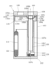
- (First embodiment) 1 is a vertical cross-sectional view of an accumulator 1 according to a first embodiment, with only the left half of the strainer shown in cross section.
- the accumulator 1 has a tank body 2, a double pipe 5 arranged in the tank body 2, a bag 11 containing a desiccant (moisture absorbent) DA, a cup (also called a gas-liquid separating member) 16, and a strainer 20.
- a desiccant moisture absorbent
- cup also called a gas-liquid separating member
- the tank body 2 includes a body 3 and a header 4.
- the body 3 is formed in a cylindrical shape with at least an opening at the top end, and as an example, is formed in a cylindrical shape with a bottom, and is a body portion with an opening at at least one end.
- the header 4 closes the opening at one end of the body 3.
- the header 4 is joined to the body 3 by circumferential joining, for example, via a weld 10, and closes the opening of the body 3.
- the body 3 and the header 4 are both formed of a metal such as an aluminum alloy.
- the header 4 side is referred to as the upper side
- the bottom side of the body 3 is referred to as the lower side.
- the body 3 may be a cylinder with openings at both ends. In this configuration, one opening is closed by the header 4, and the other opening is closed by a member separate from the body 3. In this configuration, the member that closes the other opening of the body 3 is formed of a metal such as an aluminum alloy.
- the header 4 is formed in a roughly disk-like shape, and has a refrigerant inlet hole 8 and a refrigerant outlet hole 9 formed to penetrate from top to bottom.
- An inner pipe (also called an outlet pipe) 6 that extends close to the inside bottom of the body 3 is connected to the refrigerant outlet hole 9.
- An outer pipe 7 is fitted to the outside of the inner pipe 6, thereby forming a double pipe 5.
- a cup 16 is provided below the header 4, to separate the mixed refrigerant (a mixture of gas and liquid phase refrigerant) from the refrigerant inlet 8 into high density liquid phase refrigerant and compressor oil (hereinafter referred to as "oil"), and low density gas phase refrigerant.
- the cup 16 is made of, for example, resin.
- the cup 16 has, for example, a cylindrical shape with a top, and is positioned opposite the refrigerant inlet 8 and the refrigerant outlet 9.
- the inner pipe 6 is made of, for example, a metal, and an aluminum alloy is one example of the metal.
- the lower end of the inner pipe 6 is open, and the upper end is connected to the refrigerant outlet hole 9 of the header 4 by press-fitting, as described below.
- the outer periphery of the inner pipe 6 is fitted inside a number of pipe ribs 7a protruding from the inner periphery of the outer pipe 7, so that the inner pipe 6 is stably held within the outer pipe 7 with a gap therebetween.
- the outer pipe 7 is made of, for example, synthetic resin, and is attached inside the body 3 with its upper end open.
- a cylindrical strainer 20 is provided at the bottom of the outer pipe 7.
- the strainer 20 is composed of a cylindrical case 21 with a bottom made of synthetic resin, and a cylindrical mesh filter 22 integrated with the case 21 by insert molding or the like.
- the strainer 20 may be abutted against, for example, the bottom surface of the internal space of the body 3. When the strainer 20 abuts against the bottom surface of the internal space of the body 3, the cup 16 is clamped between the body 3 and the header 4 via the inner pipe 6.
- a bag 11 containing a desiccant DA is placed between the outer pipe 7 and the inner circumference of the body 3.
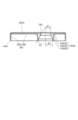
- FIG. 2 is a cross-sectional view showing the header 4, cup 16, and inner pipe 6 in an exploded state.
- FIG. 3 is a bottom view of the cup 16.
- the axis of the inner pipe 6 is designated as L.
- the header 4 is made up of a large cylindrical portion 4a and a thin-walled annular portion 4b, which is smaller in diameter than the large cylindrical portion 4a, stacked in series, and a step 4c is formed between the large cylindrical portion 4a and the thin-walled annular portion 4b, with which the outer periphery of the upper end of the body 3 engages.
- the upper surface of the large cylindrical portion 4a is formed, for example, as a plane perpendicular to the vertical direction.
- a cylindrical boss 4d is formed on the underside of the header 4, protruding downward from the large cylindrical portion 4a.
- a refrigerant outlet hole 9 is formed through the boss 4d, penetrating the header 4 from top to bottom, and a refrigerant inlet hole 8 is formed adjacent to the boss 4d, penetrating the header 4 from top to bottom.
- the underside of the boss 4d is formed, for example, on a plane that is in surface contact with the upper surface of the top wall 16b of the cup 16, which will be described later.
- the underside of the boss 4d is formed, for example, on a plane that is perpendicular to the axis L of the inner pipe 6.
- the refrigerant outlet hole 9 has a large diameter hole 9a formed at the top and a small diameter hole 9b formed at the bottom.
- the inner diameter of the large diameter hole 9a is larger than the inner diameter of the small diameter hole 9b.
- the cup 16 has a cup body (also simply called the body) 16e and an extension 16d.
- the cup body 16e faces the header 4 inside the body 3.
- the cup body 16e is formed by connecting a side wall 16a and a top wall 16b.
- a through hole 16c is formed in the top wall 16b.
- the through hole 16c is an example of a communication part in which a part of the inner pipe 6 is arranged.
- the communication part is formed in the cup body 16e in a shape that communicates the header 4 side with the opposite side, in other words, the bottom side of the body 3.
- the communication part is not limited to a through hole.
- the communication part may be a notch that penetrates the cup body 16e and opens to the side of the cup body 16e.
- one or more ribs 16b1 are formed on the upper surface of the top wall 16b in a shape that protrudes upward. The ribs 16b1 form part of the upper surface of the top wall.
- an extension portion 16d is formed around the through hole 16c, for example, on the edge of the through hole 16c.
- the extension portion 16d is formed in a shape that extends from the cup body 16e to the tapered tube portion 6c and abuts against the tapered tube portion 6c of the inner pipe 6.
- a plurality of extension portions 16d for example, four extension portions 16d, are formed.
- the extension portions 16d are formed in a wall shape.
- the extension portions 16d are described as retaining walls 16d.
- the four retaining walls 16d are arranged, for example, at equal intervals on the edge of the through hole 16c.
- the retaining walls 16d are formed to be connected to the cup body 16e.
- the underside of the top wall 16b, excluding the retaining walls 16d, is flat.
- Top wall 16b faces both refrigerant inlet hole 8 and refrigerant outlet hole 9. Furthermore, top wall 16b is a portion against which the refrigerant flowing in from refrigerant inlet hole 8 collides. Furthermore, top wall 16b faces the entire refrigerant inlet hole 8. The facing direction is the axial direction of refrigerant inlet hole 8. Furthermore, the gap between the header 4 and the top wall 16b and the gap between the side wall 16a and the inner circumferential surface of the body 3 are approximately the same. Here, “approximately the same” may include an error in addition to being completely the same.
- the refrigerant flowing in from the refrigerant inlet hole 8 collides with the top wall 16b and flows downstream, it flows through the gap between the top wall 16b and the header 4 and the gap between the inner circumferential surface of the body 3 and the side wall 16a. If these gaps are "the same", the smooth flow of the refrigerant is maintained. In addition, if there is a small error in these gaps, the state in which the refrigerant flows smoothly can be maintained. The error is an error that can maintain the flow of the refrigerant smoothly in this way.
- the retaining wall 16d has a shape that corresponds to, for example, the inner pipe 6.
- the corresponding shape means a shape that follows the outer peripheral surface of the inner pipe 6, that is, the surface of the retaining wall 16d that faces and abuts against the inner pipe 6 is formed to have the same shape or approximately the same shape as the outer peripheral surface of the inner pipe 6.
- the retaining wall 16d has a shape that is point-symmetrical with respect to the axis of the through hole 16c (which coincides with the axis L when assembled), and specifically consists of a rectangular plate-shaped base 16d1 on the top wall 16b side, a rectangular plate-shaped tip 16d2 on the lower end side, and a right-angled trapezoidal plate-shaped intermediate portion 16d3 that connects the base 16d1 and tip 16d2.
- the outer surfaces of the base 16d1, the intermediate portion 16d3, and the tip portion 16d2 on the side away from the axis of the through hole 16c are, for example, parallel to the axis of the through hole 16c.
- the distances between the inner surfaces of the base 16d1 and tip 16d2 on the side closer to the axis of the through hole 16c and the axis of the through hole 16c are R1 and R2, respectively, where R1 ⁇ R2. That is, the inner surface of the base 16d1 has the same shape or approximately the same shape as a part of the outer periphery of a cylinder with a radius of R1. The inner surface of the tip 16d2 has the same shape or approximately the same shape as a part of the outer periphery of a cylinder with a radius of R2. Therefore, the inner surface of the middle portion 16d3 close to the axis of the through hole 16c is inclined at an angle ⁇ 1 with respect to the axis of the through hole 16c.
- the inner surface of the middle portion 16d3 has the same shape or approximately the same shape as a part of the outer periphery of a truncated cone with a radius of R2 at the bottom and a radius of R1 at the top.
- the inner diameter of the small diameter hole 9b and the through hole 16c is 2 ⁇ R1.
- the area of the upper surface of the top wall 16b of the cup 16 that contacts the lower surface of the boss 4d of the header 4 is formed in a plane that is in surface contact with the lower surface of the boss 4d.
- the area of the upper surface of the top wall 16b of the cup 16 that contacts the lower surface of the boss 4d of the header 4 is formed in a plane that is perpendicular to the axis of the inner pipe 6, for example.
- a part of the rib 16b1 may be formed in the area of the upper surface of the top wall 16b of the cup 16 that contacts the lower surface of the boss 4d of the header 4.
- a recess is formed in the lower surface of the boss 4d of the header 4 in which part of the rib 16b1 is disposed. This recess has a shape that, for example, fits into the rib 16b1.
- the inner pipe 6 is made up of a small diameter cylindrical section (also called a small tube section) 6a, which is inserted into and fixed in the small diameter hole 9b of the refrigerant outflow hole 9, and a large diameter cylindrical section (also called a large tube section) 6b, which is larger in diameter than the small diameter cylindrical section 6a and is placed inside the body 3, connected by a tapered tube section 6c.
- a small diameter cylindrical section also called a small tube section
- 6b large diameter cylindrical section
- the inner pipe 6 is formed by drawing a pipe made of metal, for example aluminum.
- the outer diameter of the small diameter cylindrical portion 6a is smaller than the outer diameter of the large diameter cylindrical portion 6b, but by drawing the pipe, the fiber flow in the metal structure of the inner pipe 6 is continuous across the small diameter cylindrical portion 6a, the tapered tube portion 6c, and the large diameter cylindrical portion 6b. This continuous fiber flow can be seen by cutting the inner pipe 6 in the axial direction, and is therefore visible.
- the outer circumferential radii of the small diameter cylindrical portion 6a and the large diameter cylindrical portion 6b are r1 and r2, respectively.
- r1 is equal to R1, or r1 is approximately equal to R1.
- r1 is approximately equal to R1” includes cases where r1 is smaller than R1 and cases where r1 is larger than R1.
- r2 is equal to R2, or r2 is approximately equal to R2.
- R2 includes cases where r2 is smaller than R2 and cases where r2 is larger than R2.
- the outer peripheral surface of the tapered tube portion 6c is a truncated cone outer peripheral surface with a radius of r2 at the bottom end and a radius of r1 at the top end, or a curved surface substantially similar to the outer peripheral surface of a truncated cone with a radius of r2 at the bottom end and a radius of r1 at the top end.
- the inner pipe 6 has a small diameter inner circumferential surface (small inner circumferential surface) 6e extending inside the small diameter cylindrical portion 6a, a tapered inner circumferential surface (intermediate inner circumferential surface) 6f extending inside the tapered tube portion 6c, and a large diameter inner circumferential surface (large inner circumferential surface) 6g extending inside the large diameter cylindrical portion 6b. Since the flow direction of the refrigerant inside the inner pipe 6 is from the lower end to the upper end, the large diameter inner circumferential surface 6g, the tapered inner circumferential surface 6f, and the small diameter inner circumferential surface 6e are arranged in this order along the flow direction of the refrigerant. Since the inner pipe 6 is formed by drawing, the small diameter inner circumferential surface 6e, the tapered inner circumferential surface 6f, and the large diameter inner circumferential surface 6g are smoothly connected to each other.
- the outer peripheral surface of the tapered tube portion 6c is inclined at an angle ⁇ 2 with respect to the axis L of the inner pipe 6.
- ⁇ 2 is equal to ⁇ 1 or approximately equal to ⁇ 1. It is preferable that the angles ⁇ 1 and ⁇ 2 are, for example, 40 degrees ⁇ 10 degrees.
- the tapered tube portion 6c abuts against the middle portion 16d3 of the retaining wall 16.
- the outer peripheral surface of the tapered tube portion 6c and the inner surface of the middle portion 16d3 may be formed as curved surfaces that are in surface contact with each other. For example, when r1 is equal to R1 and r2 is equal to R2, the outer peripheral surface of the tapered tube portion 6c is a curved surface that is in surface contact with the inner surface of the middle portion 16d3.
- the tapered tube portion 6c abuts against the middle portion 16d3 and the large diameter cylindrical portion 6b abuts against the tip portion 16d2, improving the accuracy of positioning the cup 16 relative to the inner pipe 6.
- the retaining wall 16d is not shaped to abut against the inner pipe 6 only on a single plane, but the boundary portion (corner or corner) between the base portion 16d1, middle portion 16d3, and tip portion 16d2 fits into the boundary portion (corner or corner) between the small diameter cylindrical portion 6e, tapered tube portion 6c, and large diameter cylindrical portion 6b of the inner pipe 6, improving the accuracy of positioning the cup 16 relative to the inner pipe 6.
- the boundary portion between the base 16d1 and the intermediate portion 16d3 of the retaining wall 16d does not match the boundary portion between the small diameter cylindrical portion 6e and the tapered tube portion 6c of the inner pipe 6, or the boundary portion between the intermediate portion 16d3 and the tip portion 16d2 of the retaining wall 16d does not match the boundary portion between the tapered tube portion 6c and the large diameter cylindrical portion 6b of the inner pipe 6.
- the intermediate portion 16d3 of the retaining wall 16d abuts against the tapered tube portion 6c of the inner pipe 6 and the tip portion 16d2 of the retaining wall 16d abuts against the large diameter cylindrical portion 6b of the inner pipe 6, improving the accuracy of positioning the cup 16 with respect to the inner pipe portion 6.
- the middle portion 16d3 and the tip portion 16d2 of the retaining wall 16d function as a guide when inserting the inner pipe 6 into the refrigerant outlet hole 9 of the header 4, making it easier to fix the inner pipe 6 to the refrigerant outlet hole 9.
- Figure 4 is an enlarged cross-sectional view of the lower end of the inner pipe 6 of this embodiment.
- the large-diameter inner circumferential surface 6g maintains a cylindrical shape
- the outer circumferential surface of the large-diameter cylindrical portion 6b also maintains a cylindrical shape.
- the lower end 6h is an end surface that is perpendicular to the axis L.
- a pressure equalizing hole 6q is formed in the tapered cylindrical portion 6c of the inner pipe 6.
- the pressure equalizing hole 6q penetrates the inside and outside of the inner pipe 6.
- the pressure equalizing hole 6q is a hole that prevents the liquid phase refrigerant that has accumulated in the inner pipe 6 from being sucked up by the compressor when the compressor is started again after the refrigeration cycle has stopped (after the compressor has stopped operating).
- the pressure equalizing hole 6q allows not only the liquid phase refrigerant in the inner pipe 6 but also the gas phase refrigerant outside the inner pipe 6 to be sucked up by the compressor, thereby preventing the liquid phase refrigerant from being sucked up.
- the inner pipe 6 is brought close to the cup 16 from below.
- the small diameter cylindrical portion 6a of the inner pipe 6 is then inserted into the through hole 16c and press-fitted into the small diameter hole 9b of the header 4.
- the retaining wall 16d also functions to guide the small diameter cylindrical portion 6a as it enters the small diameter hole 9b.
- the outer peripheral surface of the tapered tube portion 6c abuts and engages with the inner surface of the middle portion 16d3 of the retaining wall 16d, so that the inner pipe 6 is locked and does not proceed any further toward the header 4.
- the tapered tube portion 6c abuts against the middle portion 16d3 and the large diameter cylindrical portion 6b abuts against the tip portion 16d2, improving the accuracy of positioning the cup 16 relative to the inner pipe 6. This allows the cup 16 to be held in an appropriate position.
- the small diameter cylindrical portion 6a is supported by abutting against the inner surfaces of the base portions 16d1 of the four retaining walls 16d, except for the portion pressed into the small diameter hole 9b.
- the outer peripheral surface of the tapered tube portion 6c is supported by abutting against the inner surfaces of the middle portions 16d3 of the four retaining walls 16d.
- the upper outer peripheral surface of the large diameter cylindrical portion 6b is supported by abutting against the inner surfaces of the tip portions 16d2 of the four retaining walls 16d. This allows the inner pipe 6 to be firmly held against the header 4 and cup 16, thereby suppressing vibrations, etc.
- the outer pipe 7 and strainer 20 are attached to the inner pipe 6 of the assembly thus formed, and the accumulator 1 is completed by installing it inside the body 3 in which the bag 11 is arranged, and welding it to the header 4. Unless otherwise specified, the order of the above steps is not limited to the order described.
- the small diameter cylindrical portion 6a of the inner pipe 6 is inserted into the small diameter hole 9b of the header 4 while the tapered tube portion 6c of the inner pipe 6 and the middle portion 16d3 of the retaining wall 16d are brought closer together, so that the small diameter cylindrical portion 6a of the inner pipe 6 is fixed to the small diameter hole 9b of the header 4 and the tapered tube portion 6c of the inner pipe 6 is brought into contact with the middle portion 16d3 of the retaining wall 16d, thereby clamping the cup 16 between the inner pipe 6 and the header 4.
- the small diameter cylindrical portion 6a of the inner pipe 6 may be inserted into the through hole 16c to bring the tapered tube portion 6c and the middle portion 16d3 closer together so that the tapered tube portion 6c and the middle portion 16d3 are in contact with each other, and then while maintaining this contact state, the small diameter cylindrical portion 6a may be inserted into the small diameter hole 9b to fix the small diameter cylindrical portion 6a to the small diameter hole 9b, thereby clamping the cup 16 between the inner pipe 6 and the header 4.
- a small diameter cylindrical portion 6a is formed to match the refrigerant outflow hole 9 of the header 4, and a large diameter cylindrical portion 6b is formed to obtain a flow rate according to the performance required of the accumulator 1, and further, the cup 16 can be fixed to the header 4 using the inner pipe 6. Therefore, it is possible to provide an accumulator 1 that can hold the gas-liquid separator and increase the amount of refrigerant passing through while preventing an increase in the number of parts.
- the inner pipe 6 is fixed to the header 4 by pressing the small diameter cylindrical portion 6a into the small diameter hole 9b, which eliminates the need for crimping the inner pipe 6, for example (no crimping portion is provided inside the refrigerant outflow hole 9).
- the cup 16 is attached to the header 4 by being sandwiched between the tapered cylindrical portion 6c formed on the inner pipe 6 and the boss 4d of the header 4, eliminating the need for bulge processing of the inner pipe 6. This reduces the resistance of the refrigerant flowing through the inner pipe 6 and suppresses the occurrence of turbulence, ensuring a smooth flow of the refrigerant.
- the inner pipe 6 may be fixed to the header 4 by forming a female thread on the inner circumference of the small diameter hole 9b and a male thread on the outer circumference of the small diameter cylindrical portion 6a and screwing the female thread and the male thread together.
- the male thread of the small diameter cylindrical portion 6a is preferably formed by rolling, but may be formed by cutting.
- tapered inner peripheral surface 6f of the inner pipe 6 and the outer peripheral surface of the tapered tube portion 6c are not limited to a shape with a uniform inclination angle with respect to the axis, and it is sufficient if the shape is such that the diameter decreases toward the header 4 side.
- the refrigerant When the refrigerant is discharged from the evaporator, it is transported to the accumulator 1 through a connecting pipe (not shown). After reaching the accumulator 1, the refrigerant flows into the body 3 through the refrigerant inlet 8, and then collides with the upper surface of the cup 16, where it is separated into high-density liquid-phase refrigerant and oil, and low-density gas-phase refrigerant (gas refrigerant).
- the liquid refrigerant and oil are stored in the body 3 due to their own weight. During this process, the liquid refrigerant and oil continue to separate, and the oil accumulates below the liquid refrigerant. At this time, the liquid level of the liquid refrigerant reaches a height position where part of the desiccant-containing bag 11 is immersed. Therefore, both the moisture contained in the liquid refrigerant and the humidity contained in the gas refrigerant are absorbed by the desiccant DA.
- the gas-phase refrigerant that has been separated into gas and liquid flows in from the upper opening of the outer pipe 7 and descends inside the outer pipe 7. It then turns around at the bottom of the outer pipe 7, passes over the lower end of the inner pipe 6, and flows inside, rising inside the inner pipe 6 and being led to the refrigerant outlet hole 9.
- the inner pipe 6 is formed with a tapered inner surface 6f, so the inner diameter gradually decreases toward the small-diameter inner surface 6e on the refrigerant outlet side, reducing pressure loss and ensuring an even smoother flow of the refrigerant.
- the oil that accumulates at the bottom of the body 3 together with the liquid refrigerant moves to the bottom side of the body 3 due to differences in specific gravity and properties compared to the liquid refrigerant, and is sucked into the gas refrigerant that is sucked into the compressor suction side, passing through the mesh filter 22 of the strainer 20, the oil return hole 7e, and the internal space of the inner pipe 6, in that order, before being returned to the compressor suction side together with the gas refrigerant and circulated.
- foreign matter such as sludge is captured and removed from the circulating refrigerant (including oil).
- Fig. 5 is a bottom view of the cup 16A according to the first modified example.
- Fig. 6 is a vertical cross-sectional view of the cup 16A according to the first modified example.
- the extensions instead of the configuration in which a plurality of extensions (retaining walls) are provided, the extensions are formed in a cylindrical shape. More specifically, as the extensions, a retaining cylinder 16Ad is formed on the underside of the top wall 16b around the through hole 16c, for example, on the edge of the through hole 16c.
- Other configurations are the same as those in the above-mentioned embodiment, so repeated explanations will be omitted.
- the outer diameter of the retaining cylinder 16Ad is uniform.
- the inner radii of the cylindrical base 16Ad1 and the tip cylindrical portion 16Ad2 are R1 and R2, respectively, where R1 ⁇ R2.
- the inner circumference of the intermediate cylindrical portion 16Ad3 is inclined at an angle ⁇ 1 with respect to the axis of the through hole 16c.
- the holding cylinder 16Ad of the cup 16A abuts against the outer peripheral surface of the inner pipe 6 all around. Specifically, except for the portion pressed into the small diameter hole 9b of the small diameter cylindrical portion 6a of the inner pipe 6, the holding cylinder 16Ad abuts against and is supported by the inner peripheral surface of the cylindrical base portion 16Ad1.
- the outer peripheral surface of the tapered cylindrical portion 6c abuts against and is supported by the inner peripheral surface of the intermediate cylindrical portion 16Ad3.
- the upper end outer peripheral surface of the large diameter cylindrical portion 6b abuts against and is supported by the inner peripheral surface of the tip cylindrical portion 16Ad2.
- Fig. 7 is an enlarged cross-sectional view of the lower end of the inner pipe 6B according to the second modification.
- the outer circumferential surface of the large-diameter cylindrical portion 6Bb has a cylindrical shape up to the lower end 6Bh of the inner pipe 6B, but the large-diameter inner circumferential surface 6Bg gradually expands in diameter from the vicinity of the lower end 6Bh toward the lower end 6Bh, and intersects with the outer circumferential surface of the large-diameter cylindrical portion 6Bb at the lower end 6Bh.
- the large-diameter inner circumferential surface 6Bg near the lower end 6Bh preferably has an arc shape.
- Fig. 9 is an enlarged cross-sectional view of the lower end of the inner pipe 6D according to the fourth modified example.
- the large-diameter inner circumferential surface 6Dg gradually expands in diameter from the vicinity of the lower end 6Dh of the inner pipe 6D toward the lower end 6Dh
- the outer circumferential surface of the large-diameter cylindrical portion 6Db gradually decreases in diameter from the vicinity of the lower end 6Dh toward the lower end 6Dh
- the large-diameter inner circumferential surface 6Dg and the outer circumferential surface of the large-diameter cylindrical portion 6Db intersect at the lower end 6Dh.
- the lower end wall of the large-diameter cylindrical portion 6Cb near the lower end 6Dh preferably has a semicircular arc shape.
- the gas-liquid separated gas-phase refrigerant when the gas-liquid separated gas-phase refrigerant turns around at the bottom of the outer pipe 7 and heads toward the lower end 6Dh of the inner pipe 6D, it flows along the outer peripheral surface of the gradually narrowing large diameter cylindrical portion 6Db, and when it passes the lower end 6Dh of the inner pipe 6D and flows inward, it flows along the gradually expanding large diameter inner peripheral surface 6Dg, ensuring a smooth flow of the refrigerant.
- Fig. 10 is a vertical cross-sectional view of an accumulator 1F according to a second embodiment.
- the outflow pipe 6F is U-shaped and does not have an outer pipe.
- Fig. 10 omits a strainer and a bag containing a desiccant.
- the configuration of the outflow pipe 6F is different from that of the above-mentioned embodiment, and other configurations are the same as those of the above-mentioned embodiment, so duplicated explanations will be omitted.
- the outflow pipe 6F in this embodiment is composed of a small diameter cylindrical section 6Fa and a large diameter U-shaped cylindrical section 6Fb bent into a U shape, connected by a tapered cylindrical section 6Fc.
- the outer diameter of the small diameter cylindrical section 6Fa is approximately equal to the inner diameter of the small diameter hole 9b.
- the small diameter cylindrical section 6Fa, the tapered cylindrical section 6Fc, and the upper end of the large diameter U-shaped cylindrical section 6Fb have the same shapes as in the above-mentioned embodiment.
- the outflow pipe 6F can be formed by drawing the end of a U-shaped pipe.
- the small diameter cylindrical portion 6Fa of the outflow pipe 6F is inserted into the through hole 16c, and then the small diameter cylindrical portion 6Fa is fixed by press fitting into the small diameter hole 9b of the header 4.
- the cup 16 is clamped and fixed between the retaining wall 16d and the lower end of the boss 4d.
- the outflow pipe 6F can be attached by moving it linearly without rotating it relative to the header 4, so that the free end of the outflow pipe 6F can be positioned inside the cup 16 in the assembly position shown in Figure 10.
- Third Embodiment 11 is a vertical cross-sectional view of an accumulator 1G according to the third embodiment.
- the accumulator 1G of this embodiment is different from the accumulator 1F of the second embodiment in the shape of the outflow pipe 6G.
- the bending radius of the bent portion of the large-diameter U-shaped cylindrical portion 6Gb of the outflow pipe 6G is larger than the bending radius of the corresponding portion of the outflow pipe 6F of the third embodiment.
- the rest of the configuration is the same as that of the above-mentioned embodiment.
- the small diameter cylindrical portion 6Ga, the tapered tube portion 6Gc, and the upper end of the large diameter U-shaped tube portion 6Gb have the same shapes as in the first embodiment.
- the outflow pipe 6G can be formed by drawing the end of a U-shaped pipe.
- the outflow pipe 6G has a small diameter inner circumferential surface 6Ge extending within the small diameter cylindrical portion 6Ga, a tapered inner circumferential surface 6Gf extending within the tapered tubular portion 6Gc, and a large diameter inner circumferential surface 6Gg extending within the large diameter U-shaped tubular portion 6Gb.
- the outflow pipe 6G has a pressure equalizing hole 6Gq in the tapered inner circumferential surface 6Gf, similar to the above-mentioned embodiment.
- the header 104 is formed in a roughly disk shape, and a refrigerant inlet hole 108 and a refrigerant outlet hole 109 are formed penetrating vertically.
- An inner pipe (also called an outlet pipe) 106 that extends close to the inside bottom of the body 3 is connected to the refrigerant outlet hole 109.
- An outer pipe 107 is fitted on the outside of the inner pipe 106, thereby forming a double pipe 105.
- a cup 116 is provided as a gas-liquid separating member that separates the mixed refrigerant (a mixture of gas and liquid phase refrigerant) from the refrigerant inlet 108 into high density liquid phase refrigerant and compressor oil (hereinafter referred to as "oil") and low density gas phase refrigerant.
- the cup 116 is made of, for example, resin.
- the cup 116 has, for example, a cylindrical shape with a top, and is positioned opposite the refrigerant inlet 108 and the refrigerant outlet 109.
- the inner pipe 106 is made of, for example, a metal, and an aluminum alloy is used as one example.
- the lower end of the inner pipe 106 is open, and the upper end is screwed into the refrigerant outlet hole 109 of the header 104, as described below.
- the outer periphery of the inner pipe 106 is fitted inside a number of pipe ribs 107a protruding from the inner periphery of the outer pipe 107, so that the inner pipe 106 is stably held within the outer pipe 107 with a gap therebetween.
- the outer pipe 107 is made of, for example, synthetic resin, and is attached inside the body 3 with its upper end open.
- a cylindrical strainer 120 is provided at the bottom of the outer pipe 107.
- the strainer 120 is composed of a cylindrical case 121 with a bottom made of synthetic resin, and a cylindrical mesh filter 122 that is integrated with the case 121 by insert molding or the like.
- a bag 111 containing a desiccant DA is placed between the outer pipe 107 and the inner circumference of the body 103.
- the header 104 is made up of a large cylindrical portion 104a and a thin annular portion 104b, which is smaller in diameter than the large cylindrical portion 104a, stacked in series, and a step portion 104c is formed between the large cylindrical portion 104a and the thin annular portion 104b, with which the outer periphery of the upper end of the body 103 engages.
- the upper surface of the large cylindrical portion 104a is formed, for example, as a plane perpendicular to the vertical direction.
- a cylindrical boss 104d is formed on the underside of the header 104, protruding downward from the large cylindrical portion 104a.
- a refrigerant outlet hole 109 is formed through the boss 104d and penetrating the header 104 from top to bottom, and a refrigerant inlet hole 108 is formed adjacent to the boss 104d and penetrating the header 104 from top to bottom.
- the underside of the boss 104d is formed, for example, on a plane that is in surface contact with the bottom surface of a cylindrical recess (also called a recess) 116c of the cup 116, which will be described later.
- the underside of the boss 104d is formed, for example, on a plane that is perpendicular to the axis L of the inner pipe 106.
- the refrigerant outlet hole 109 has a large diameter hole 109a formed at the top and a small diameter hole 109b formed at the bottom, and a female thread 109c is formed in the small diameter hole 109b.
- the inner diameter of the large diameter hole 109a is larger than the thread diameter of the female thread 109c.
- the cup 116 of this embodiment can be formed, for example, by press-forming a metal plate.
- the cup 116 is formed by connecting a side wall 116a and a top wall 116b.
- a portion of the top wall 116b is plastically deformed so as to shift downward in correspondence with the boss 104d, thereby forming a cylindrical recess 116c.
- the inner diameter of the cylindrical recess 116c is approximately equal to the outer diameter of the boss 104d.
- one or more ribs may be formed on the upper surface of the top wall 116b.
- a circular hole 116d is formed through the bottom wall of the cylindrical recess 116c.
- the inner diameter of the circular hole 116d is slightly larger than the inner diameter of the small diameter hole 109b.
- the bottom surface of the cylindrical recess 116c of the cup 116 is formed in a plane that is in surface contact with the lower surface of the boss 104d of the header 104.
- the bottom surface of the cylindrical recess 116c of the cup 116 is formed in a plane that is perpendicular to the axis of the inner pipe 106, for example, in the range where the lower surface of the boss 104d of the header 104 abuts.
- the inner pipe 106 is made of a metal pipe of uniform diameter that is expanded near the upper end by bulging, and compressed in the axial direction to form a flange 106a that protrudes radially outward from the entire outer periphery.
- a male thread 106b is also formed on the outer periphery of the upper end of the inner pipe 106.
- the method of forming the flange 106a is not limited to bulging.
- the flange 106a may be formed by bead processing (string processing).
- a pressure equalizing hole 106q is formed below the flange 106a.
- the pressure equalizing hole 106q penetrates the inside and outside of the inner pipe 106.
- the pressure equalizing hole 106q is a hole that prevents the liquid phase refrigerant that has accumulated in the inner pipe 106 from being sucked up by the compressor when the compressor is started again after the refrigeration cycle has stopped (after the compressor has stopped operating).
- the pressure equalizing hole 106q allows not only the liquid phase refrigerant in the inner pipe 106 but also the gas phase refrigerant outside the inner pipe 106 to be sucked up by the compressor, thereby preventing the liquid phase refrigerant from being sucked up.
- the inner pipe 106 may have a flat surface at its lower end perpendicular to the axis L, as in the embodiment shown in FIG. 4, or the inner diameter surface may expand as it approaches the lower end, as in the embodiment shown in FIG. 7, the outer diameter surface may decrease as it approaches the lower end, as in the embodiment shown in FIG. 8, or the inner diameter surface may expand and the outer diameter surface may decrease as it approaches the lower end, as in the embodiment shown in FIG. 9.
- the boss 104d of the header 104 is inserted into the cylindrical recess 116c of the cup 116, and the lower end of the boss 104d is brought into contact with the bottom surface of the cylindrical recess 116c. This causes the small diameter hole 109b and the circular hole 116d to be coaxially aligned.
- the inner pipe 106 is brought close to the cup 116 from below.
- the upper end of the inner pipe 106 is then inserted into the circular hole 116d, and the male thread 106b is screwed into the female thread 109c of the small diameter hole 109b of the header 104.
- the flange 106a approaches the header 4 and comes into contact with the underside of the cylindrical recess 116c.
- the inner pipe 106 is locked with the cup 116 sandwiched between it and does not approach any further toward the header 104.
- the cup 116 is sandwiched between the underside of the boss 104d of the header 104 and the flange 106a of the inner pipe 106 and is held stably. This allows the cup 116 to be held in an appropriate position.
- the outer pipe 107 and strainer 120 are attached to the inner pipe 106 of the assembly formed in this manner, and the assembly is installed inside the body 103 in which the bag 111 is arranged, and then welded to the header 104 to complete the accumulator 101.
- the inner pipe 106 is fixed to the header 104 by screwing the male thread 106a into the female thread 109c of the small diameter hole 109b, which means that, for example, crimping of the inner pipe 106 is not necessary (no crimping portion is provided inside the refrigerant outflow hole 109).
- the refrigerant When the refrigerant is discharged from the evaporator, it is transported to the accumulator 101 through a connecting pipe (not shown). After reaching the accumulator 101, the refrigerant flows into the body 103 through the refrigerant inlet hole 108, and then collides with the upper surface of the cup 116, where it is separated into high-density liquid-phase refrigerant and oil, and low-density gas-phase refrigerant (gas refrigerant).
- the annular retaining cylinder 16A is described as one example of an extension portion, but the retaining cylinder 16A is not limited to being formed in a continuous annular shape.
- the retaining cylinder 16A may be formed in a C-shape in a plan view.
- the retaining cylinder 16A has an outer shape formed in a cylindrical shape, but is not limited to a cylindrical shape.
- the outer shape may be a polygonal prism, such as a square prism.
- the inner surface of the tip portion 16d2 is formed as a flat surface
- the inner surface of the tip portion 16d2 is formed as a flat surface that abuts against the large diameter cylindrical portion 6b of the inner pipe 6 and the large diameter U-shaped tubular portion 6Fb of the outflow pipes 6F, 6G, thereby obtaining the same effect as described above.
- the cups 16, 116 are one example of a gas-liquid separating member.
- the gas-liquid separating member faces both the refrigerant inlet holes 8, 108 and the refrigerant outlet holes 9, 109.
- the gas-liquid separating member has a portion with which the refrigerant flowing in from the refrigerant inlet holes 8, 108 collides.
- the gas-liquid separating member preferably faces the entire area of the refrigerant inlet holes 8, 108.
- the facing direction is the axial direction of the refrigerant inlet holes 8, 108.
- the gas-liquid separation member preferably has a top wall facing both the entire refrigerant inlet holes 8, 108 and the refrigerant outlet holes 9, 109, and a cylindrical side wall facing the inner circumferential surface of the body 3, 103.
- the gap between the header 4, 104 and the top wall and the gap between the inner circumferential surface of the body 3, 103 and the side wall are approximately the same.
- approximately the same means that in addition to being completely the same, it may include an error. That is, when the refrigerant flowing in from the refrigerant inlet hole 8, 108 collides with the top wall and flows downstream, it flows through the gap between the top wall and the header 4, 104 and the gap between the inner circumferential surface of the body 3, 103 and the side wall.
- the top wall of the gas-liquid separating member is not limited to being in the form of a plate having a constant thickness. Furthermore, another example of the gas-liquid separating member has a structure that does not include a side wall.
- a body portion having an opening at at least one end; a header having a refrigerant inlet and a refrigerant outlet and closing one end of the body portion; a gas-liquid separating member accommodated in the body portion, the gas-liquid separating member having a communication portion formed in a portion facing the refrigerant outflow hole, the communication portion communicating the header side with an opposite side; an outflow pipe that is accommodated in the body portion, a portion of which is disposed in the communication portion, and which is connected to the refrigerant outflow hole, the outflow pipe has a small cylinder portion inserted into and fixed to the refrigerant outflow hole, a large cylinder portion disposed within the body portion and having a cross-sectional area larger than that of the small cylinder portion, and a tapered cylinder portion connecting the small cylinder portion and the large cylinder portion,
- the inner circumferential surface of the outflow pipe has, along a flow direction of the refrigerant,
- the outflow pipe is formed into a cylindrical shape having a circular cross-sectional shape. 12.
- the extension portion is provided in a plurality of portions in a circumferential direction of the outflow pipe.
- the accumulator according to any one of the first to third aspects, characterized in that
- the outflow pipe is formed by drawing or expanding the pipe.
- the outflow pipe is press-fitted into the refrigerant outflow hole.
- a body portion having an opening at at least one end; a header having a refrigerant inlet and a refrigerant outlet and closing one end of the body portion; an outflow pipe housed in the body portion and connected to the refrigerant outflow hole,
- the outlet pipe has a male thread formed at an end thereof,
- the refrigerant outlet hole has a female thread,
- the outflow pipe is attached to the header by threading the male thread into the female thread.
- a gas-liquid separating member accommodated in the body portion the gas-liquid separating member having a communication portion formed in a portion facing the refrigerant outflow hole, the communication portion communicating the header side with the opposite side;
- the outflow pipe has a flange portion protruding radially outward from an outer circumferential surface in the vicinity of the male thread, a portion of the outflow pipe is disposed in the communication portion, The gas-liquid separating member is held between the flange portion and the header in a state in which the outflow pipe is attached to the header.
- the header has a boss portion around the refrigerant outlet hole, the gas-liquid separating member has a recess that fits into the boss portion, When the outflow pipe is attached to the header, a bottom wall of the recess is held between the flange portion and the boss portion.
- the gas-liquid separation member is formed by press-molding a metal plate material. 14.
Landscapes
- Engineering & Computer Science (AREA)
- Chemical & Material Sciences (AREA)
- Analytical Chemistry (AREA)
- Power Engineering (AREA)
- Physics & Mathematics (AREA)
- Mechanical Engineering (AREA)
- Thermal Sciences (AREA)
- General Engineering & Computer Science (AREA)
- Compressor (AREA)
Priority Applications (2)
| Application Number | Priority Date | Filing Date | Title |
|---|---|---|---|
| CN202480010800.3A CN120936840A (zh) | 2023-04-19 | 2024-04-12 | 储液器及其制造方法 |
| JP2025515205A JPWO2024219332A1 (https=) | 2023-04-19 | 2024-04-12 |
Applications Claiming Priority (2)
| Application Number | Priority Date | Filing Date | Title |
|---|---|---|---|
| JP2023-068652 | 2023-04-19 | ||
| JP2023068652 | 2023-04-19 |
Publications (1)
| Publication Number | Publication Date |
|---|---|
| WO2024219332A1 true WO2024219332A1 (ja) | 2024-10-24 |
Family
ID=93152407
Family Applications (1)
| Application Number | Title | Priority Date | Filing Date |
|---|---|---|---|
| PCT/JP2024/014821 Ceased WO2024219332A1 (ja) | 2023-04-19 | 2024-04-12 | アキュームレータおよびその製造方法 |
Country Status (3)
| Country | Link |
|---|---|
| JP (1) | JPWO2024219332A1 (https=) |
| CN (1) | CN120936840A (https=) |
| WO (1) | WO2024219332A1 (https=) |
Citations (5)
| Publication number | Priority date | Publication date | Assignee | Title |
|---|---|---|---|---|
| JPS61127368U (https=) * | 1985-01-29 | 1986-08-09 | ||
| JPS6392167U (https=) * | 1986-12-05 | 1988-06-15 | ||
| JPH0457170U (https=) * | 1990-09-21 | 1992-05-15 | ||
| US6062039A (en) * | 1998-01-07 | 2000-05-16 | Parker-Hannifin Corporation | Universal accumulator for automobile air conditioning systems |
| JP2014070869A (ja) * | 2012-10-02 | 2014-04-21 | Fuji Koki Corp | アキュムレータ |
-
2024
- 2024-04-12 WO PCT/JP2024/014821 patent/WO2024219332A1/ja not_active Ceased
- 2024-04-12 CN CN202480010800.3A patent/CN120936840A/zh active Pending
- 2024-04-12 JP JP2025515205A patent/JPWO2024219332A1/ja active Pending
Patent Citations (5)
| Publication number | Priority date | Publication date | Assignee | Title |
|---|---|---|---|---|
| JPS61127368U (https=) * | 1985-01-29 | 1986-08-09 | ||
| JPS6392167U (https=) * | 1986-12-05 | 1988-06-15 | ||
| JPH0457170U (https=) * | 1990-09-21 | 1992-05-15 | ||
| US6062039A (en) * | 1998-01-07 | 2000-05-16 | Parker-Hannifin Corporation | Universal accumulator for automobile air conditioning systems |
| JP2014070869A (ja) * | 2012-10-02 | 2014-04-21 | Fuji Koki Corp | アキュムレータ |
Also Published As
| Publication number | Publication date |
|---|---|
| JPWO2024219332A1 (https=) | 2024-10-24 |
| CN120936840A (zh) | 2025-11-11 |
Similar Documents
| Publication | Publication Date | Title |
|---|---|---|
| CN101688716B (zh) | 气液分离器及搭载其的空气调节器 | |
| US20080148768A1 (en) | Receiver tank for a condensor and method of manufacturing the same | |
| CN106895613B (zh) | 膨胀阀 | |
| CA2409535C (en) | Baffle connection for an accumulator and related method of manufacturing | |
| WO2024219332A1 (ja) | アキュームレータおよびその製造方法 | |
| JP2013134004A (ja) | アキュムレータ及びアキュムレータの製造方法 | |
| JP7840595B2 (ja) | アキュームレータ | |
| EP3940279B1 (en) | Expansion valve | |
| EP1681500B1 (en) | Non-return valve | |
| JP2002295927A (ja) | アキュムレシーバ、冷凍装置及びアキュムレシーバの製造方法 | |
| US12117251B2 (en) | Heat exchanger | |
| JP2013137111A (ja) | アキュムレータ | |
| WO2023017782A1 (ja) | アキュームレータ | |
| JP3299467B2 (ja) | 空調用冷媒受液器 | |
| JP2007232335A (ja) | 冷媒容器とその製造方法 | |
| JP2022019265A (ja) | 逆止弁および冷凍サイクルシステム | |
| CN203810810U (zh) | 储液罐一体型冷凝器、储液罐 | |
| EP2123999A1 (en) | Expansion valve | |
| JP2026032363A (ja) | タンク | |
| JP2026037728A (ja) | 圧縮機および冷凍サイクル装置 | |
| JP2007046798A (ja) | 気液分離器およびその製造方法 | |
| EP2102566A2 (en) | Accumulator for automotive refrigeration system | |
| JP2001336863A (ja) | 熱交換器 | |
| KR20250145393A (ko) | 조립 장치, 조립 방법 및 커넥터 조립체 | |
| KR20160041239A (ko) | 리시버 드라이어 캡필터 및 그 조립 방법 |
Legal Events
| Date | Code | Title | Description |
|---|---|---|---|
| 121 | Ep: the epo has been informed by wipo that ep was designated in this application |
Ref document number: 24792607 Country of ref document: EP Kind code of ref document: A1 |
|
| WWE | Wipo information: entry into national phase |
Ref document number: 2025515205 Country of ref document: JP |
|
| NENP | Non-entry into the national phase |
Ref country code: DE |
|
| 122 | Ep: pct application non-entry in european phase |
Ref document number: 24792607 Country of ref document: EP Kind code of ref document: A1 |