WO2024218978A1 - 光合成測定方法、光合成測定装置およびプログラム - Google Patents
光合成測定方法、光合成測定装置およびプログラム Download PDFInfo
- Publication number
- WO2024218978A1 WO2024218978A1 PCT/JP2023/015984 JP2023015984W WO2024218978A1 WO 2024218978 A1 WO2024218978 A1 WO 2024218978A1 JP 2023015984 W JP2023015984 W JP 2023015984W WO 2024218978 A1 WO2024218978 A1 WO 2024218978A1
- Authority
- WO
- WIPO (PCT)
- Prior art keywords
- chamber
- gas
- flow rate
- measurement
- plant
- Prior art date
- Legal status (The legal status is an assumption and is not a legal conclusion. Google has not performed a legal analysis and makes no representation as to the accuracy of the status listed.)
- Ceased
Links
Images




Classifications
-
- A—HUMAN NECESSITIES
- A01—AGRICULTURE; FORESTRY; ANIMAL HUSBANDRY; HUNTING; TRAPPING; FISHING
- A01G—HORTICULTURE; CULTIVATION OF VEGETABLES, FLOWERS, RICE, FRUIT, VINES, HOPS OR SEAWEED; FORESTRY; WATERING
- A01G7/00—Botany in general
Definitions
- Embodiments of the present invention relate to a photosynthesis measurement method, a photosynthesis measurement device, and a program.
- the open type is the most commonly used photosynthetic measurement system for plants.
- a plant or part of a plant is enclosed in a measurement chamber with a fixed volume, and a gas containing a certain concentration of CO2 is flowed into the chamber at a constant flow rate, and the photosynthetic rate is measured based on the difference in CO2 concentration between the air flowing in and out of the chamber.
- an open-type photosynthetic measurement device employing an open system is used.
- This invention was made in light of the above-mentioned circumstances, and its purpose is to provide a photosynthesis measurement method, photosynthesis measurement device, and program that enable appropriate comparison of photosynthetic responses between chambers of different volumes when the photosynthetic responses are evaluated.
- a photosynthesis measurement method is a method executed by a photosynthesis measurement device, which includes the steps of: flowing a gas containing carbon dioxide into a first chamber in which a first plant is sealed and a second chamber in which a second plant is sealed; controlling the concentration of carbon dioxide contained in the gas in the first and second chambers to change from a current value to a predetermined target value; and measuring the time required for the concentration of carbon dioxide in the first chamber to change from the current value to a value intermediate between the current value and the target value under each of a plurality of conditions for the flow rate of the gas in the first chamber when performing the control.
- a photosynthesis measuring device includes a control unit that causes a gas containing carbon dioxide to flow into a first chamber in which a first plant is sealed and a second chamber in which a second plant is sealed, and controls the concentration of carbon dioxide contained in the gas in the first and second chambers to change from a current value to a predetermined target value, and measures the time required for the concentration of carbon dioxide in the first chamber to change from the current value to a value intermediate between the current value and the target value under each of a plurality of conditions for the flow rate of the gas in the first chamber when the control unit is performing the control, and performs the control by the control unit.
- the apparatus includes a measurement unit that measures the time required for the concentration of carbon dioxide in the second chamber to change from the current value to an intermediate value between the current value and the target value under each of a plurality of conditions for the flow rate of gas in the second chamber, and an estimation unit that estimates the flow rates of gas flowing into the first chamber and the second chamber when the replacement rate of gas in the first chamber and the replacement rate of gas in the second chamber are equal based on the results of the measurement by the measurement unit, as the flow rates under the conditions for measuring the photosynthetic rate of the first plant and the second plant, respectively.
- the photosynthetic responses when photosynthetic responses are evaluated using chambers with different volumes, the photosynthetic responses can be appropriately compared between chambers.
- FIG. 1 is a diagram showing an example of the change in CO2 concentration in a measurement chamber.
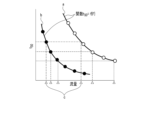
- FIG. 2 is a diagram showing an example of the relationship between the time when the CO2 concentration reaches a predetermined concentration and the gas flow rate.
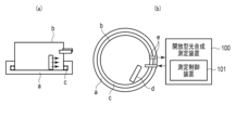
- FIG. 3 is a diagram showing an application example of a photosynthesis measurement system according to an embodiment of the present invention.
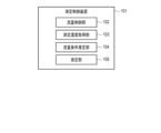
- FIG. 4 is a block diagram showing an example of a functional configuration of the measurement control device.
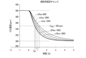
- FIG. 5A is a diagram showing an example of changes in CO2 concentration in a single-leaf measurement chamber.
- FIG. 5B shows an example of the change in CO2 concentration in an individual measurement chamber.
- FIG. 6 is a diagram showing an example of the relationship between the flow rate and the elapsed time until a predetermined CO 2 concentration is reached when the CO 2 concentration is changed in each measurement chamber.
- FIG. 7 is a diagram showing an example of the change over time in the photosynthetic rate after light irradiation.
- Figure 8 is a block diagram showing an example of the hardware configuration of a measurement control device according to one embodiment of the present invention.
- FIG. 1 is a diagram showing an example of the change in CO2 concentration in a measurement chamber.
- the curve showing the change in CO2 concentration over time shows a saturation curve in which the concentration increases linearly in the early stage of the change from C1 to C2, and then increases relatively slowly to reach C2.
- the time required from the start of the change from C1 to the CO2 concentration C50 % which is the intermediate CO2 concentration between C1 and C2, that is, the time required for the CO2 concentration to change from C1 to C50 % , is defined as time t50 .
- C50% is expressed as the following formula (1).
- C 50% C1+(C2-C1)/2...Formula (1)
- the change in CO2 concentration over time from the timing corresponding to the start point of the change on the graph shows a saturation type curve, and when the gas flow rate is high (symbol b in FIG. 1), the time t50 is shorter than when the gas flow rate is low (symbol c in FIG. 1).
- FIG. 2 is a diagram showing an example of the relationship between the time when the CO2 concentration reaches a predetermined concentration and the gas flow rate.
- a measurement chamber for a first plant e.g., a measurement chamber for an individual leaf (sometimes referred to as a chamber for individual leaves) having a relatively small volume and in which a first plant, e.g., an individual leaf of a plant, is enclosed
- a measurement chamber for an individual plant sometimes referred to as a chamber for individual plants
- a second plant e.g., an individual plant
- a function derived for an individual measurement chamber having a relatively large volume symbol a in Figure 2
- a function derived for an individual measurement chamber having a relatively small volume symbol b in Figure 2
- the photosynthetic response to environmental changes between a single leaf and an individual plant is compared when an individual leaf of a plant is enclosed in a chamber with a relatively small volume and an individual plant is enclosed in a chamber with a relatively large volume.
- the present invention is not limited to this, and the application is not particularly limited as long as the photosynthetic response to environmental changes between different plants is compared when different plants are enclosed in two chambers with different gas replacement rates under the same flow rate conditions.
- the time t50individual can be calculated, which is the time it takes for the individual measurement chamber to reach a CO2 concentration C50 % when an arbitrary flow rate is set.
- the flow rate at which the time reaches the calculated time t50 (individual) i.e., the flow rate at which the gas replacement rates are equal between the measurement chambers (symbol c in Figure 2), can be calculated based on the functions derived above for each of the individual chamber and the single leaf chamber .
- the flow rate of gas flowing into the measurement chamber for an individual leaf and the flow rate of gas flowing into the measurement chamber for an individual leaf when the time t50 is equal between the measurement chamber for an individual leaf and the measurement chamber for an individual can be estimated.
- the flow rate at which the gas replacement rates of the individual leaf measurement chamber and the individual plant measurement chamber, which have different volumes, are equal can be calculated.
- FIG. 3 is a diagram showing an application example of a photosynthesis measurement system according to an embodiment of the present invention.
- an acrylic measurement chamber for measuring an individual plant Arabidopsis thaliana (thale cress)
- This measurement chamber is composed of two parts: (1) a transparent circular bottom plate a having an edge on its outer periphery capable of accommodating an O-ring c (described later), and (2) a cylindrical cover b with an open bottom, and has a volume of 2385 cm3 .
- the cylindrical cover b is attached so that it is stored inside the edge of the circular bottom plate a.
- An O-ring c is installed on the inner circumference of the circular bottom plate a to prevent gas leakage between the edge of the circular bottom plate a and the cylindrical cover b when the cylindrical cover b is attached to the circular bottom plate a.
- the cylindrical cover b is provided with a small gas stirring fan d, whose rotation speed can be controlled according to the applied voltage, and two holes which are an air inlet and outlet e.
- a silicone tube which is a ventilation tube, is inserted into the air inlet and outlet e, and this tube is connected to the external open-type photosynthesis measurement device 100.
- This open-type photosynthesis measurement device 100 is provided with a measurement control device 101.
- This measurement control device 101 may be provided in a form that is incorporated into the open-type photosynthesis measurement device 100, or may be provided as a separate device that can be connected to the open-type photosynthesis measurement device 100 so as to be able to communicate with it.
- FIG. 4 is a block diagram showing an example of a functional configuration of the measurement control device.
- the measurement control device 101 of the open-type photosynthesis measurement device 100 has a flow control unit 102, a measured concentration acquisition unit 103, a flow condition estimation unit 104, and a measurement unit 105.
- the flow control unit 102 causes a gas containing CO2 to flow into the single-leaf measurement chamber and the individual measurement chamber, and controls the concentration of CO2 contained in the gas in each chamber to change from the current value to a predetermined target value.
- 5A and 5B are diagrams showing an example of a change in CO2 concentration in a measurement chamber for individual leaves and plants, respectively.
- an open photosynthesis measurement device 100 and a measurement chamber with a volume of 102 cm3 were used as the single-leaf measurement chamber.
- An example is described in which the change in CO2 concentration over time was measured when the CO2 concentration was changed from 400 ppm to 300 ppm under multiple flow rate conditions for each of the measurement chambers for single leaves and individuals.
- the CO2 concentration in each measurement chamber is controlled by the flow control unit 102 of the open-type photosynthesis measurement device 100, and the change in CO2 concentration for 10 minutes after control begins is measured at 10-second intervals.
- the CO2 concentration can be measured at flow rates of 100, 125, 150, 175, 200, 250, 300, 400, 500, 600, and 800 [ ⁇ mol ⁇ s ⁇ 1 ] and acquired by the measured concentration acquisition unit 103.
- Fig. 5A shows the measurement results of the CO2 concentration at flow rates of 100, 125, 150, 175, 200, 250, and 300 [ ⁇ mol ⁇ s ⁇ 1 ] (symbols a to g in Fig. 5A ).
- the CO2 concentration is measured at flow rates of 800, 1000, 1250, 1500, and 1600 [ ⁇ mol ⁇ s -1 ] (symbols a to e in FIG. 5B) and can be acquired by the measured concentration acquisition unit 103.
- the higher the gas flow rate the faster the rate of change in the CO2 concentration and the shorter the time t50 .
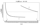
- FIG. 6 is a diagram showing an example of the relationship between the flow rate and the elapsed time until a predetermined CO 2 concentration is reached when the CO 2 concentration is changed in each measurement chamber.
- the time t50 is plotted against the flow rate when the CO2 concentration is changed from 400 [ppm] to 300 [ppm] for each measurement chamber.
- the plotted result for the measurement chamber for single leaves (symbol a in Fig. 6) and the plotted result for the measurement chamber for individuals (symbol b in Fig. 6) are shown.
- the above function which takes the flow rate as an argument and the time t50 as a return value, can be derived as an exponential function for the single leaf measurement chamber, and as a quadratic function for the individual measurement chamber. Using these derived functions, the flow rate condition estimation unit 104 of the measurement control device 101 can estimate the flow rate at which the time t50 is equal in both chambers, i.e., the flow rate that equalizes the gas replacement rate in both chambers.
- the flow rate of gas flowing into the measurement chamber for an individual leaf and the flow rate of gas flowing into the measurement chamber for an individual leaf when the time t50 is equal between the measurement chamber for an individual leaf and the measurement chamber for an individual can be estimated.
- the environmental conditions in each measurement chamber are controlled by the open-type photosynthesis measurement device 100, and the photosynthetic rate can be measured by the measurement unit 105 of the open-type photosynthesis measurement device 100, with the environmental conditions being a temperature of 26°C and the estimated flow rate of 122 ⁇ mol ⁇ s -1 when measuring individual leaves, and with the emotional conditions being a temperature of 26°C and the estimated flow rate of 1600 ⁇ mol ⁇ s -1 when measuring individuals, with the CO2 concentration in both chambers being 400 ppm and the humidity being 55 to 80%.
- the above-ground part of the plant body is excised and a similar measurement is performed by the measuring unit 105, so that the respiration rate of the soil and roots is measured, and the photosynthetic rate of the individual can be calculated by subtracting this value from the respiration rate at the time of the measurement of the individual.
- a t is the photosynthetic rate at a certain time point.
- a min is the photosynthetic rate before light irradiation.
- a max is the maximum photosynthetic rate reached after light irradiation.
- FIG. 7 is a diagram showing an example of the change over time in the photosynthetic rate after light irradiation.
- FIG. 7 shows that after a change in light intensity, the photosynthetic rate of an individual leaf (symbol a in FIG. 7 ) and the photosynthetic rate of an individual plant (symbol b in FIG. 7 ) increase gradually and eventually reach a constant rate, and it is clear that an individual plant shows a faster photosynthetic response compared to an individual leaf.
- One embodiment of the present invention makes it possible to appropriately compare the photosynthetic response of plants to environmental changes between individual leaves and individuals.
- FIG. 8 is a block diagram showing an example of a hardware configuration of a measurement control device 101 according to an embodiment of the present invention.
- the measurement control device 101 according to the embodiment is configured, for example, by a server computer or a personal computer, and has a hardware processor 111A such as a CPU.
- a program memory 111B, a data memory 112, an input/output interface 113, and a communication interface 114 are connected to this hardware processor 111A via a bus 115.
- the communication interface 114 includes, for example, one or more wireless communication interface units, and enables transmission and reception of information to and from a communication network NW.
- the wireless interface for example, an interface that adopts a low-power wireless data communication standard such as a wireless LAN (Local Area Network) is used.
- An input device 300 and an output device 400 that are attached to the measurement control device 101 and used by a user or the like are connected to the input/output interface 113 .
- the input/output interface 113 takes in operation data input by a user or the like through an input device 300 such as a keyboard, a touch panel, a touchpad, a mouse, etc., and outputs output data to an output device 400 including a display device using liquid crystal or organic EL (Electro Luminescence), etc., for display.
- the input device 300 and the output device 400 may be devices built into the measurement control device 101, or may be input devices and output devices of other information terminals that can communicate with the measurement control device 101 via the network NW.
- the program memory 111B is a non-transient tangible storage medium that combines a non-volatile memory such as a HDD (Hard Disk Drive) or SSD (Solid State Drive) that can be written to and read from at any time, with a non-volatile memory such as a ROM (Read Only Memory), and stores the programs necessary to execute various control processes, etc. according to one embodiment.
- a non-volatile memory such as a HDD (Hard Disk Drive) or SSD (Solid State Drive) that can be written to and read from at any time
- a non-volatile memory such as a ROM (Read Only Memory)
- ROM Read Only Memory
- the data memory 112 is a tangible storage medium that is a combination of the above-mentioned non-volatile memory and a volatile memory such as RAM (Random Access Memory), and is used to store various data acquired and created during various processing steps.
- RAM Random Access Memory
- the measurement control device 101 can be configured as a data processing device having a processing function unit implemented by software.
- the storage area used as a work memory by the measurement control device 101 can be configured by using the data memory 112 shown in Fig. 8.
- these configured storage areas are not essential components within the measurement control device 101, and may be areas provided in a storage device such as an external storage medium such as a Universal Serial Bus (USB) memory, or a database server located in the cloud.
- USB Universal Serial Bus
- the above processing function unit can be realized by having the above hardware processor 111A read and execute a program stored in the program memory 111B. Note that this processing function unit may also be realized in a variety of other forms, including integrated circuits such as an application specific integrated circuit (ASIC (Application Specific Integrated Circuit)) or an FPGA (Field-Programmable Gate Array).
- ASIC Application Specific Integrated Circuit
- FPGA Field-Programmable Gate Array
- the methods described in each embodiment can be stored as a program (software means) that can be executed by a computer on a recording medium such as a magnetic disk (floppy disk, hard disk, etc.), optical disk (CD-ROM, DVD, MO, etc.), semiconductor memory (ROM, RAM, flash memory, etc.), and can be distributed by transmitting it via a communication medium.
- the programs stored on the medium also include a setting program that configures the software means (including not only execution programs but also tables and data structures) that the computer executes.
- the computer that realizes this device reads the program recorded on the recording medium, and in some cases configures the software means using the setting program, and executes the above-mentioned processing by having the operation controlled by this software means.
- the recording medium referred to in this specification is not limited to a recording medium for distribution, but also includes storage media such as a magnetic disk or semiconductor memory installed inside the computer or in a device connected via a network.
- the methods described in each embodiment can be stored as a program (software means) that can be executed by a computer on a recording medium such as a magnetic disk (floppy disk, hard disk, etc.), optical disk (CD-ROM, DVD, MO, etc.), semiconductor memory (ROM, RAM, Flash memory, etc.), and can be distributed by transmitting it via a communication medium.
- the programs stored on the medium also include a setting program that configures the software means (including not only execution programs but also tables and data structures) that the computer executes.
- the computer that realizes this device reads the program recorded on the recording medium, and in some cases configures the software means using the setting program, and executes the above-mentioned processing by having the operation controlled by this software means.
- the recording medium referred to in this specification is not limited to one for distribution, but also includes storage media such as magnetic disks and semiconductor memories installed inside the computer or in devices connected via a network.
- the present invention is not limited to the above-described embodiments, and can be modified in various ways during implementation without departing from the gist of the invention.
- the embodiments may also be implemented in appropriate combination, in which case the combined effects can be obtained.
- the above-described embodiments include various inventions, and various inventions can be extracted by combinations selected from the multiple constituent elements disclosed. For example, if the problem can be solved and an effect can be obtained even if some constituent elements are deleted from all the constituent elements shown in the embodiments, the configuration from which these constituent elements are deleted can be extracted as an invention.
- Reference Signs List 100 Open-type photosynthesis measurement device 101: Measurement control device 102: Flow rate control unit 103: Measured concentration acquisition unit 104: Flow rate condition estimation unit 105: Measurement unit
Landscapes
- Life Sciences & Earth Sciences (AREA)
- Biodiversity & Conservation Biology (AREA)
- Botany (AREA)
- Ecology (AREA)
- Forests & Forestry (AREA)
- Environmental Sciences (AREA)
- Investigating Or Analysing Biological Materials (AREA)
Priority Applications (2)
| Application Number | Priority Date | Filing Date | Title |
|---|---|---|---|
| PCT/JP2023/015984 WO2024218978A1 (ja) | 2023-04-21 | 2023-04-21 | 光合成測定方法、光合成測定装置およびプログラム |
| JP2025515025A JPWO2024218978A1 (https=) | 2023-04-21 | 2023-04-21 |
Applications Claiming Priority (1)
| Application Number | Priority Date | Filing Date | Title |
|---|---|---|---|
| PCT/JP2023/015984 WO2024218978A1 (ja) | 2023-04-21 | 2023-04-21 | 光合成測定方法、光合成測定装置およびプログラム |
Publications (1)
| Publication Number | Publication Date |
|---|---|
| WO2024218978A1 true WO2024218978A1 (ja) | 2024-10-24 |
Family
ID=93152299
Family Applications (1)
| Application Number | Title | Priority Date | Filing Date |
|---|---|---|---|
| PCT/JP2023/015984 Ceased WO2024218978A1 (ja) | 2023-04-21 | 2023-04-21 | 光合成測定方法、光合成測定装置およびプログラム |
Country Status (2)
| Country | Link |
|---|---|
| JP (1) | JPWO2024218978A1 (https=) |
| WO (1) | WO2024218978A1 (https=) |
Citations (5)
| Publication number | Priority date | Publication date | Assignee | Title |
|---|---|---|---|---|
| JPS56157956U (https=) * | 1980-04-21 | 1981-11-25 | ||
| JPH08172913A (ja) * | 1994-12-28 | 1996-07-09 | Tokyo Gas Co Ltd | 光合成速度測定方法 |
| US20030204989A1 (en) * | 2001-11-23 | 2003-11-06 | Pierre Tocquin | Device allowing measurement of photosyntesis of a whole small plant |
| JP2007274908A (ja) * | 2006-04-03 | 2007-10-25 | Japan International Research Center For Agricultural Services | バッファーチャンバー方式ガス収支測定装置 |
| JP2020134262A (ja) * | 2019-02-18 | 2020-08-31 | 大学共同利用機関法人自然科学研究機構 | 測定装置 |
-
2023
- 2023-04-21 WO PCT/JP2023/015984 patent/WO2024218978A1/ja not_active Ceased
- 2023-04-21 JP JP2025515025A patent/JPWO2024218978A1/ja active Pending
Patent Citations (5)
| Publication number | Priority date | Publication date | Assignee | Title |
|---|---|---|---|---|
| JPS56157956U (https=) * | 1980-04-21 | 1981-11-25 | ||
| JPH08172913A (ja) * | 1994-12-28 | 1996-07-09 | Tokyo Gas Co Ltd | 光合成速度測定方法 |
| US20030204989A1 (en) * | 2001-11-23 | 2003-11-06 | Pierre Tocquin | Device allowing measurement of photosyntesis of a whole small plant |
| JP2007274908A (ja) * | 2006-04-03 | 2007-10-25 | Japan International Research Center For Agricultural Services | バッファーチャンバー方式ガス収支測定装置 |
| JP2020134262A (ja) * | 2019-02-18 | 2020-08-31 | 大学共同利用機関法人自然科学研究機構 | 測定装置 |
Also Published As
| Publication number | Publication date |
|---|---|
| JPWO2024218978A1 (https=) | 2024-10-24 |
Similar Documents
| Publication | Publication Date | Title |
|---|---|---|
| Zhang et al. | High sensitivity of compound drought and heatwave events to global warming in the future | |
| Mauritsen et al. | Tuning the MPI‐ESM1. 2 global climate model to improve the match with instrumental record warming by lowering its climate sensitivity | |
| Luoto et al. | Uncertainty of bioclimate envelope models based on the geographical distribution of species | |
| Álvarez-Dávila et al. | Forest biomass density across large climate gradients in northern South America is related to water availability but not with temperature | |
| Ibrahim et al. | Changes in rainfall regime over Burkina Faso under the climate change conditions simulated by 5 regional climate models | |
| CN114662742B (zh) | 大田灌溉施肥制度动态决策方法及装置 | |
| Groenendijk et al. | Performance assessment of nitrate leaching models for highly vulnerable soils used in low-input farming based on lysimeter data | |
| Sander et al. | Common practices for manual greenhouse gas sampling in rice production: a literature study on sampling modalities of the closed chamber method | |
| Hargreaves et al. | Linking glacial and future climates through an ensemble of GCM simulations | |
| Liu et al. | How global warming alters future maize yield and water use efficiency in China | |
| Karimi et al. | Diagnostic framework for evaluating how parametric uncertainty influences agro‐hydrologic model projections of crop yields under climate change | |
| Pichuka et al. | Spatio-temporal downscaling of projected precipitation in the 21st century: indication of a wetter monsoon over the Upper Mahanadi Basin, India | |
| CN110969200A (zh) | 基于一致性负样本的图像目标检测模型训练方法及装置 | |
| CN107530412A (zh) | 用于主动监控前列腺癌的组合物和方法 | |
| CN116757490A (zh) | 一种植被碳汇评估方法、系统、电子设备及存储介质 | |
| Serra-Varela et al. | Incorporating exposure to pitch canker disease to support management decisions of Pinus pinaster Ait. in the face of climate change | |
| WO2024218978A1 (ja) | 光合成測定方法、光合成測定装置およびプログラム | |
| Lee et al. | Evaluation of the sensitivity to ionising γ-radiation of a Cymbidium hybrid | |
| Yao et al. | Convergence and differentiation of tree radial growth in the Northern Hemisphere | |
| Kunwor et al. | Preserving the variance in imputed eddy-covariance measurements: Alternative methods for defensible gap filling | |
| Jobst et al. | D-vine Generalized Additive Model copula-based quantile regression with application to ensemble postprocessing | |
| Saha et al. | Improved framework for attribution analysis of contributing climatic factors influencing reference evapotranspiration | |
| Yu et al. | Estimating non-additive within-season temperature effects on maize yields using Bayesian approaches | |
| CN103222210A (zh) | 一种多径衰落模拟方法和多径衰落模拟装置 | |
| Liu et al. | Inflated negative impacts of temperature on global agricultural yields due to ozone omission |
Legal Events
| Date | Code | Title | Description |
|---|---|---|---|
| 121 | Ep: the epo has been informed by wipo that ep was designated in this application |
Ref document number: 23934120 Country of ref document: EP Kind code of ref document: A1 |
|
| ENP | Entry into the national phase |
Ref document number: 2025515025 Country of ref document: JP Kind code of ref document: A |
|
| WWE | Wipo information: entry into national phase |
Ref document number: 2025515025 Country of ref document: JP |
|
| NENP | Non-entry into the national phase |
Ref country code: DE |
|
| 122 | Ep: pct application non-entry in european phase |
Ref document number: 23934120 Country of ref document: EP Kind code of ref document: A1 |