WO2024218878A1 - 異常判定装置、異常判定システム、および異常判定方法 - Google Patents
異常判定装置、異常判定システム、および異常判定方法 Download PDFInfo
- Publication number
- WO2024218878A1 WO2024218878A1 PCT/JP2023/015523 JP2023015523W WO2024218878A1 WO 2024218878 A1 WO2024218878 A1 WO 2024218878A1 JP 2023015523 W JP2023015523 W JP 2023015523W WO 2024218878 A1 WO2024218878 A1 WO 2024218878A1
- Authority
- WO
- WIPO (PCT)
- Prior art keywords
- correction value
- past
- setting information
- current
- unit
- Prior art date
- Legal status (The legal status is an assumption and is not a legal conclusion. Google has not performed a legal analysis and makes no representation as to the accuracy of the status listed.)
- Ceased
Links
Images

Classifications
-
- G—PHYSICS
- G05—CONTROLLING; REGULATING
- G05B—CONTROL OR REGULATING SYSTEMS IN GENERAL; FUNCTIONAL ELEMENTS OF SUCH SYSTEMS; MONITORING OR TESTING ARRANGEMENTS FOR SUCH SYSTEMS OR ELEMENTS
- G05B19/00—Program-control systems
- G05B19/02—Program-control systems electric
- G05B19/18—Numerical control [NC], i.e. automatically operating machines, in particular machine tools, e.g. in a manufacturing environment, so as to execute positioning, movement or co-ordinated operations by means of program data in numerical form
-
- G—PHYSICS
- G05—CONTROLLING; REGULATING
- G05B—CONTROL OR REGULATING SYSTEMS IN GENERAL; FUNCTIONAL ELEMENTS OF SUCH SYSTEMS; MONITORING OR TESTING ARRANGEMENTS FOR SUCH SYSTEMS OR ELEMENTS
- G05B19/00—Program-control systems
- G05B19/02—Program-control systems electric
- G05B19/18—Numerical control [NC], i.e. automatically operating machines, in particular machine tools, e.g. in a manufacturing environment, so as to execute positioning, movement or co-ordinated operations by means of program data in numerical form
- G05B19/406—Numerical control [NC], i.e. automatically operating machines, in particular machine tools, e.g. in a manufacturing environment, so as to execute positioning, movement or co-ordinated operations by means of program data in numerical form characterised by monitoring or safety
Definitions
- This disclosure relates to an abnormality determination device, an abnormality determination system, and an abnormality determination method that perform abnormality determination of correction values set in a machine tool.
- Machine tools process the workpiece while correcting the tool position, etc.
- Machine tools perform processing while correcting the tool position based on the amount of tool position correction input by the operator. For this reason, it is desirable for the amount of correction input by the operator to be an appropriate amount of correction.
- the machine tool control device described in Patent Document 1 corrects the amount of tool movement according to a correction amount input by an operator, and stores the input correction amount, correction timing, and operator ID as historical data. Then, when a stored operator ID is selected, the machine tool control device automatically corrects the amount of tool movement according to the correction amount and correction timing corresponding to this operator ID, and performs machining.
- Patent Document 1 predicts and automatically corrects the correction value using an approximation formula, which creates a problem in that there is a high possibility that an inappropriate correction value predicted by the approximation formula will be adopted, and the machining will be performed with the automatic correction using the inappropriate correction value.
- the present disclosure has been made in consideration of the above, and aims to provide an abnormality determination device that can perform processing while reducing the possibility of correction with an inappropriate correction value.
- the abnormality determination device disclosed herein includes an operator input unit that receives from an operator a correction value that is set for the operation of a tool defined in a machining program used by the machine tool as a current correction value, and a setting information comparison unit that compares the current correction value set in the machine tool with a past correction value that was set for the operation of the tool when machining was performed appropriately in the past.
- the abnormality determination device disclosed herein also includes an abnormality detection unit that detects an abnormality in the current correction value based on a correction value difference, which is the difference between the current correction value and the past correction value, and a display control unit that causes a display device to display information indicating that the current correction value is inappropriate when the abnormality detection unit detects an abnormality.
- the abnormality determination device disclosed herein has the effect of reducing the possibility of correction with an inappropriate correction value and allowing processing to be performed.
- Embodiment 1 is a diagram showing a configuration of an abnormality determination system according to an embodiment.
- Abnormality determination system 1 includes a machine tool 10 and a server 30.
- Abnormality determination system 1 is a system (fault detection system) that determines a correction value set for a tool or the like before machine tool 10 starts machining, and notifies an operator of at least one of an appropriate correction value candidate (reset candidate value) and an alarm if a setting error occurs.
- the machine tool 10 has an operator input unit 11, a machining program operation unit 12, a machining inference unit 13, a setting information storage unit 14, a learned model storage unit 21, a display control unit 22, and a display device 23.
- the server 30 has a setting information acquisition unit 31, a setting information storage unit 32, a setting information comparison unit 33, an anomaly detection unit 34, a data acquisition unit 41, and a model generation unit 42.
- the data acquisition unit 41 and the model generation unit 42 are learning devices.
- At least one of the trained model storage unit 21 and the display control unit 22 may be disposed outside the machine tool 10. At least one of the trained model storage unit 21 and the display control unit 22 may be disposed, for example, within the server 30.
- At least one of the data acquisition unit 41 and the model generation unit 42 may be located outside the server 30. At least one of the data acquisition unit 41 and the model generation unit 42 may be located, for example, within the machine tool 10.
- the operator input unit 11 accepts data input by an operator.
- the operator input unit 11 accepts, for example, processing setting information, difference thresholds, and the like input by the operator.
- the processing setting information input by the operator includes processing program information, correction information, and tool number (tool identification information).
- the information on the machining program is, for example, a program number (program identification information).
- the program number is information that identifies the machining program.
- FIG. 1 shows a case where the operator input unit 11 has received a program number as information on the machining program.
- the program number may be any information that identifies a machining program for machining a workpiece.
- the correction information is information in which a correction number (correction identification information) is associated with a correction value.
- the correction value is, for example, a value for correcting the operation of a tool, which is set for the operation of the tool defined in the machining program.
- the correction number is information for identifying the correction item corresponding to the correction value.
- the correction number may be any information that identifies the correction item corresponding to the correction value. For example, if the correction item is the amount of movement of the tool, "001" is set as the correction number. In this case, in the correction information, "001" is associated with the correction value for the amount of movement of the tool defined in the machining program.
- the tool number is information for identifying a tool.
- the tool number may be any information that identifies a tool.
- the difference threshold is a threshold for the difference between an appropriate correction value used in the past (hereinafter, sometimes referred to as a past correction value) and the correction value currently being set (hereinafter, sometimes referred to as a current correction value).
- the setting information may include information other than the program number as information about the machining program.
- the machining program information may include, for example, a timestamp, shape information, machining command information (e.g., M code, G code), etc.
- the timestamp is information indicating the date and time when the machining program was created
- the shape information is information indicating the shape of the product to be produced by the machining program.
- the information included in the machining program information is not limited to the information described above.
- the machining program information may include at least one of the program number, timestamp, and shape information.
- the setting information includes information on the correction value and the machining program.
- the setting information may also include at least one of a correction number and a tool number.
- the machine tool 10 uses various machining programs and various setting information to machine various workpieces. In this embodiment, a case will be described in which the setting information input by the operator is a program number, correction information, and tool number.
- the operator input unit 11 sends the program number, the correction information, and the tool number to the machining program operation unit 12. In other words, the operator input unit 11 sends the setting information for the machining process to the machining program operation unit 12.
- the operator input unit 11 also stores the difference threshold in the setting information storage unit 14.
- the operator input unit 11 also sends the difference threshold to the anomaly detection unit 34 of the server 30. Note that the connection line connecting the operator input unit 11 and the anomaly detection unit 34 is not shown in FIG. 1.
- the machining program operation unit 12 accepts setting information including a program number, compensation information, and tool number from the operator input unit 11.
- the machining program operation unit 12 sends setting information associating the program number, compensation information, and tool number to the machining inference unit 13.
- the machining program operation unit 12 also sends setting information associating the program number, compensation information, and tool number to the setting information comparison unit 33 of the server 30.
- the setting information sent by the machining program operation unit 12 to the machining inference unit 13 and the setting information comparison unit 33 is the setting information currently set in the machine tool 10 (hereinafter sometimes referred to as current setting information).
- the trained model storage unit 21 stores the trained model generated by the model generation unit 42 of the server 30.
- the trained model is a function for inferring whether the processing performed using the current correction value (hereinafter, may be referred to as the current processing) is the same as a normal processing performed using a past correction value (hereinafter, may be referred to as the past processing).
- the trained model is used to determine whether the current processing and the past processing are the same processing.
- the same machining process is one that is executed using the same machining program and the same tools in the past and the current process, and the difference between the past correction value used in the normal machining process executed in the past and the current correction value is equal to or less than the difference threshold value.
- the processing inference unit 13 receives current setting information from the processing program operation unit 12 and reads out the learned model from the learned model storage unit 21. By inputting the current setting information into the learned model, the processing inference unit 13 infers whether the current processing to be executed and the past processing are the same processing.
- the processing inference unit 13 determines that the current processing and the past processing are not the same processing, it sends this determination result to the display control unit 22. Also, if the processing inference unit 13 determines that the current processing and the past processing are the same processing, it stores the current setting information in the setting information storage unit 14. That is, the processing inference unit 13 stores the program number, the correction information, and the tool number in the setting information storage unit 14.
- the setting information storage unit 14 stores the processing success/failure information, the current setting information sent from the processing inference unit 13, and the difference threshold value sent from the operator input unit 11.
- the processing success/failure information is information that indicates whether the currently executed processing was normal or abnormal.
- the processing success/failure information is determined based on factors such as the shape of the finished product produced by the current processing.
- the display control unit 22 When the display control unit 22 receives information from the processing inference unit 13 indicating that the current processing process and the past processing process are not the same processing process, it causes the display device 23 to display information indicating that the current processing process and the past processing process cannot be compared.
- the display control unit 22 When the display control unit 22 receives information from the server 30 indicating that the setting information (correction value) is inappropriate, the display control unit 22 causes the display device 23 to display an alarm indicating that the correction value is inappropriate. When the display control unit 22 receives a candidate correction value (reset candidate value) included in the setting information from the server 30, the display control unit 22 causes the display device 23 to display the reset candidate value. When the display control unit 22 receives information from the server 30 indicating that the correction value is appropriate, the display control unit 22 causes the display device 23 to display information indicating that the correction value is appropriate.
- the setting information acquisition unit 31 reads the current setting information and the difference threshold from the setting information storage unit 14 and stores them in the setting information accumulation unit 32. Furthermore, when the setting information storage unit 14 stores the processing success/failure information, the setting information acquisition unit 31 reads the processing success/failure information from the setting information storage unit 14. That is, after the current processing is completed, the setting information acquisition unit 31 reads the processing success/failure information from the setting information storage unit 14. The setting information acquisition unit 31 associates the read processing success/failure information with the current setting information and the difference threshold already stored in the setting information storage unit 14, and stores it in the setting information accumulation unit 32. Note that the setting information storage unit 14 may transmit the processing success/failure information, the current setting information, and the difference threshold to the setting information acquisition unit 31.
- the setting information accumulation unit 32 has a collection database that stores collected data, and in this collection database, it stores processing success/failure information, setting information, and a difference threshold in association with each other.
- the setting information stored by the setting information accumulation unit 32 is past setting information. In this way, the setting information is current setting information before processing is completed, and becomes past setting information when it is associated with processing success/failure information after processing is completed. Note that the past setting information does not need to include the difference threshold.
- the setting information comparison unit 33 receives current setting information in which a program number, correction information, and tool number are associated with each other from the machining program operation unit 12.
- the setting information comparison unit 33 may read out the current setting information from the setting information storage unit 14, or may receive the current setting information from the setting information storage unit 14.
- the setting information comparison unit 33 also reads out past setting information having the same program number and tool number as the program number and tool number included in the current setting information from the setting information accumulation unit 32. Note that the setting information comparison unit 33 may read out multiple pieces of past setting information from the setting information accumulation unit 32.
- the setting information comparison unit 33 compares the current setting information with the past setting information. Specifically, the setting information comparison unit 33 compares the correction value of the correction information included in the current setting information with the correction value of the correction information included in the past setting information. If the setting information comparison unit 33 reads out multiple past correction values, it compares the average value of the multiple past correction values with the current correction value. The setting information comparison unit 33 may also compare the most frequent or median value of the multiple past correction values with the current correction value.
- the setting information comparison unit 33 calculates the difference between the correction value of the correction information included in the current setting information and the correction value of the correction information included in the past setting information (hereinafter, sometimes referred to as the correction value difference), and sends the correction value difference to the anomaly detection unit 34.
- the abnormality detection unit 34 judges whether the current setting information (correction value) is an appropriate value based on the correction value difference sent from the setting information comparison unit 33 and the difference threshold value sent from the operator input unit 11. If the correction value difference is equal to or greater than the difference threshold value, the abnormality detection unit 34 judges that the current correction value is inappropriate, and if the correction value difference is smaller than the difference threshold value, it judges that the current correction value is appropriate.
- the abnormality detection unit 34 determines that the current correction value is appropriate, it sends information indicating that the current correction value is appropriate to the display control unit 22. If the abnormality detection unit 34 determines that the current correction value is inappropriate, it sends information (alarm) indicating that the current correction value is inappropriate to the display control unit 22.
- the abnormality detection unit 34 determines that the current correction value is inappropriate, it acquires from the setting information comparison unit 33 the past correction value used for comparison by the setting information comparison unit 33. That is, the abnormality detection unit 34 acquires from the setting information comparison unit 33, among the past correction values, the past correction value that has been compared with the current correction value that has been determined to be inappropriate.
- the abnormality detection unit 34 determines a reset candidate value that is a candidate for an appropriate correction value based on the acquired past correction value. For example, the abnormality detection unit 34 determines the average value of the acquired past correction values as the reset candidate value. That is, the abnormality detection unit 34 determines the average value of the past correction values that have been compared with the current correction value that has been determined to be inappropriate as the reset candidate value.
- the abnormality detection unit 34 sends the determined reset candidate value to the display control unit 22.
- the data acquisition unit 41 acquires setting information including information on the machining program, tools, and compensation values when machining is performed normally as learning data.
- the learning data is data in which the program number, tool number, and compensation information when machining is performed normally are associated with each other.
- the data acquisition unit 41 acquires the learning data, for example, from the setting information storage unit 32.
- the data acquisition unit 41 acquires learning data for cases where machining is successful, based on the machining success/failure information registered in the setting information storage unit 32.
- the data acquisition unit 41 may acquire the learning data from the machine tool 10.
- the data acquisition unit 41 sends the learning data, including the setting information, to the model generation unit 42.
- the model generation unit 42 uses the learning data to generate a trained model for inferring whether the current processing is the same as a processing that was performed successfully in the past.
- the trained model is used to determine whether the current processing and a past processing are the same processing.
- the model generation unit 42 stores the generated trained model in the trained model storage unit 21.
- the abnormality determination system 1 may be composed of one device, or may be composed of three or more devices.
- the abnormality determination system 1 may be an abnormality determination device including components of the machine tool 10 and components of the server 30.
- the abnormality determination device includes, for example, an operator input unit 11, a machining inference unit 13, a setting information storage unit 32, a setting information comparison unit 33, an abnormality detection unit 34, and a display control unit 22.
- the abnormality determination device may also include a machining program operation unit 12.
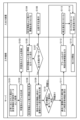
- FIG. 2 is a flowchart showing the procedure of processing executed by the abnormality determination system according to the embodiment.
- the input/output device shown in FIG. 2 is a device that receives information input by an operator, or a device that provides information to an operator.
- the input/output device here is the operator input unit 11 and the display device 23 of the machine tool 10.
- the setting information acquisition unit 31 of the server 30 acquires the setting information, the difference threshold, and the processing success/failure information from the setting information storage unit 14.
- the setting information accumulation unit 32 stores the processing success/failure information, the difference threshold, and the setting information in association with each other.
- the data acquisition unit 41 acquires, as learning data, the setting information in the case where processing was successful (step S101). That is, the data acquisition unit 41 acquires, as learning data, the setting information in which the processing success/failure information indicates that processing was successful.
- the data acquisition unit 41 acquires the learning data, for example, from the setting information accumulation unit 32, and sends it to the model generation unit 42.
- the setting information for the learning data includes, for example, a program number, a tool number, and compensation information (compensation number and compensation value). Note that the information included in the setting information for the learning data is not limited to the information described above.
- the model generation unit 42 generates a trained model using the learning data (step S102) and sends it to the machine tool 10. Specifically, the model generation unit 42 learns whether the current machining process is the same as the past machining process based on the learning data created based on a combination of the program number, tool number, and correction information when machining is performed normally. In other words, the model generation unit 42 generates a trained model that infers whether the current machining process is the same as the past machining process from the setting information when machining is performed normally by the machine tool 10.
- the model generation unit 42 may learn whether the current machining process is the same as a past machining process according to the learning data created for multiple machine tools 10.
- the model generation unit 42 may acquire learning data from multiple machine tools 10 used in the same area, or may acquire learning data collected from multiple machine tools 10 operating independently in different areas. Even when the model generation unit 42 acquires learning data from multiple machine tools 10, it learns whether the current machining process is the same as a past machining process by the same process as when learning data is acquired from one machine tool 10.
- the machine tool 10 from which learning data is collected may be added to or removed from the collection targets at any time.
- a learning device data acquisition unit 41 and model generation unit 42
- the learned model may be updated by re-learning whether or not the current machining process for the other machine tool 10 is the same as a past machining process.
- the machine tool 10 stores the learned model in the learned model storage unit 21 (step S103).
- the operator input unit 11 accepts the current setting information and difference threshold input by the operator (step S104).
- the timing at which the operator inputs the current setting information and difference threshold to the operator input unit 11 may be, for example, the timing at which the machining program is set (before the cycle starts), but is not limited to this timing.
- the difference threshold may be, for example, the allowable value of the difference when comparing a past correction value with a current correction value, but is not limited to this allowable value.
- the operator input unit 11 sends the received current setting information and difference threshold to the server 30 (step S105). Specifically, the operator input unit 11 sends the current setting information to the setting information comparison unit 33 via the machining program operation unit 12, and sends the difference threshold corresponding to the current setting information to the abnormality detection unit 34. As a result, the server 30 acquires the current setting information and difference threshold (step S106).
- the operator input unit 11 also sends the setting information to the machining inference unit 13 via the machining program operation unit 12.
- the machining inference unit 13 accepts the current setting information from the machining program operation unit 12 and reads out the learned model from the learned model storage unit 21. By inputting the current setting information into the learned model, the machining inference unit 13 determines whether the current machining process (the contents currently set in the machine tool 10) and the past machining process (the contents previously set in the machine tool 10) are the same machining process (step S107).
- the processing inference unit 13 uses the learned model stored in the learned model storage unit 21 to infer the identity of the processing by unsupervised learning. That is, the processing inference unit 13 inputs the setting information input by the operator into the learned model, and infers to which cluster the setting information belongs. In other words, the processing inference unit 13 infers whether the current processing corresponding to the setting information input by the operator corresponds to which past processing.
- the processing inference unit 13 uses a trained model learned by the model generation unit 42 of the server 30 to infer whether a processing operation is the same as a past processing operation.
- the processing inference unit 13 may obtain a trained model from an external source, such as another machine tool 10, and infer whether a processing operation is the same as a past processing operation based on this trained model.
- the inference device may also be a device separate from the machine tool 10, for example, connected to the machine tool 10 via a network.
- the learning device may be built into the machine tool 10.
- the learning device may be a device separate from the server 30, for example, connected to the server 30 via a network.
- both the learning device and the inference device may exist on the server 30.
- step S107 If the processing inference unit 13 determines that the current processing and the past processing are not the same processing (step S107, No), it sends this determination result to the display control unit 22.
- the display control unit 22 causes the display device 23 to display information indicating that the current setting information and the past setting information cannot be compared (information indicating that comparison is not possible) (step S108). This enables the machine tool 10 to notify the operator that the current correction value cannot be compared with the past correction value.
- the processing inference unit 13 determines that the current processing and the past processing are the same processing (Yes in step S107), it stores the current setting information in the setting information storage unit 14.
- the setting information acquisition unit 31 reads the current setting information from the setting information storage unit 14 and stores it in the setting information accumulation unit 32.
- the setting information comparison unit 33 receives current setting information in which a program number, compensation information, and tool number are associated with each other from the machining program operation unit 12. The setting information comparison unit 33 also reads out from the setting information storage unit 32 past compensation information that has the same program number and tool number as the program number and tool number included in the current setting information.
- the setting information comparison unit 33 compares the current setting information with the setting information accumulated in the past (step S109). Specifically, the setting information comparison unit 33 compares the correction value of the correction information included in the current setting information with the correction value of the correction information included in the past setting information.
- the setting information comparison unit 33 may compare setting information not only between the same machine tool 10, but also between different machine tools 10. In other words, the setting information comparison unit 33 may compare the current setting information with setting information previously set on a machine tool 10 different from the machine tool 10 on which the current setting information is set.
- the setting information comparison unit 33 calculates a correction value difference, which is the difference between the correction value of the correction information included in the current setting information and the correction value of the correction information included in the past setting information, and sends the correction value difference to the anomaly detection unit 34.
- the abnormality detection unit 34 determines whether the current setting information (correction value) is an abnormal value based on the correction value difference sent from the setting information comparison unit 33 and the difference threshold value sent from the operator input unit 11 (step S110).
- the abnormality detection unit 34 determines that the current correction value is an abnormal setting if the correction value difference is equal to or greater than the difference threshold, and determines that the current correction value is a normal setting if the correction value difference is smaller than the difference threshold.
- the abnormality detection unit 34 can also determine that the correction value difference is normal if it is less than a specific percentage (e.g., half) of the difference threshold, determine that there is a possibility of an abnormality if it is equal to or greater than half the difference threshold and smaller than the difference threshold, and determine that there is an abnormality if it is equal to or greater than the difference threshold.
- the abnormality detection unit 34 determines that the current correction value is appropriate (step S110, no problem)
- it sends information indicating that the current correction value is appropriate to the display control unit 22.
- the display control unit 22 causes the display device 23 to display information indicating that the correction value is appropriate.
- the machine tool 10 then enters a state in which it can accept an instruction to start machining, i.e., a state in which it can accept a cycle start instruction.
- the abnormality detection unit 34 determines that the current correction value is inappropriate (step S110, there is a problem), it sends an alarm to the display control unit 22 indicating that the current correction value is inappropriate.
- the abnormality detection unit 34 determines that the current correction value is inappropriate, it acquires from the setting information comparison unit 33 the past correction value (the correction value accumulated in the past) used for comparison by the setting information comparison unit 33.
- the abnormality detection unit 34 calculates a reset candidate value based on the acquired correction value accumulated in the past (step S111).
- the previously stored correction values used by the abnormality detection unit 34 are not limited to correction values used on the same machine tool 10, but may be correction values used on a machine tool 10 other than the machine tool 10 on which the current correction value is set.
- the anomaly detection unit 34 sends the determined reset candidate value to the display control unit 22. For example, the anomaly detection unit 34 sends the average value of previously accumulated correction values to the display control unit 22 as the reset candidate value. The anomaly detection unit 34 may also send a range of previously accumulated normal correction values to the display control unit 22 as the reset candidate value. The anomaly detection unit 34 may also send the reset candidate value represented in a histogram, taking into account the frequency of use as a normal correction value, to the display control unit 22. In other words, the anomaly detection unit 34 may send a histogram including information on the frequency of use of past correction values used as normal correction values to the display control unit 22 as the reset candidate value.
- the display control unit 22 of the machine tool 10 outputs an alarm indicating that the correction value is inappropriate and the reset candidate value to the display device 23 (step S112). This causes the display device 23 to display the alarm and the reset candidate value.
- the display device 23 may display the reset candidate values in a list, may display them in a histogram, or may display the reset candidate value that has been used most frequently (the most frequent value). After the reset candidate value is displayed, the machine tool 10 is ready to accept a correction value from the operator.
- the operator input unit 11 accepts the correction value input by the operator (step S113). That is, the operator input unit 11 accepts the problem solution (revised correction value) input by the operator based on the alarm and the reset candidate value displayed on the machine tool 10.
- the machine tool 10 may use the current correction value. That is, the machine tool 10 may use a corrected correction value input by the operator, or may use the original correction value as is.
- the machine tool 10 receives the correction value, it becomes capable of receiving an instruction to start machining, i.e., a cycle start instruction.
- the operator input unit 11 accepts the cycle start instruction (step S114).
- the operator input unit 11 accepts the cycle start instruction, for example, when a cycle start button for instructing the start of machining is pressed. This causes the machine tool 10 to start machining (cycle start) using the input correction value (step S115).
- the machine tool 10 completes machining, the shape of the finished product is measured and a determination is made as to whether it was completed successfully.
- the machine tool 10 accepts machining success/failure information, which is the result of the success/failure determination, and stores it in the setting information storage unit 14.
- the machine tool 10 associates the setting information with the machining success/failure information and stores them in the setting information storage unit 14. As a result, the setting information stored in the setting information storage unit 14 becomes past setting information.
- the setting information acquisition unit 31 reads out past setting information, difference threshold, and processing success/failure information from the setting information storage unit 14.
- the setting information acquisition unit 31 stores the past setting information, difference threshold, and processing success/failure information in the setting information accumulation unit 32. As a result, the past setting information, difference threshold, and processing success/failure information are accumulated in the setting information accumulation unit 32.
- the setting information acquisition unit 31 may store the current setting information in the setting information accumulation unit 32 when the current processing is being performed, and store the processing success/failure information in the setting information accumulation unit 32 after the current processing is completed. In this case, too, the setting information acquisition unit 31 associates the setting information, the difference threshold, and the processing success/failure information and stores them in the setting information storage unit 14. Storing the setting information, the difference threshold, and the processing success/failure information in the setting information storage unit 14 may be performed periodically at a specific cycle.
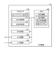
- FIG. 3 is a diagram showing an example of a hardware configuration for realizing a machine tool according to an embodiment.
- the machine tool 10 can be realized by an input device 300, a processor 100, a memory 200, an output device 400, and a display device 23.
- An example of the processor 100 is a CPU (also called a Central Processing Unit, central processing unit, processing unit, arithmetic unit, microprocessor, microcomputer, or DSP (Digital Signal Processor)) or a system LSI (Large Scale Integration).
- An example of the memory 200 is a RAM (Random Access Memory) or a ROM (Read Only Memory).
- the machine tool 10 is realized by the processor 100 reading and executing a computer-executable processing program for executing the operation of the machine tool 10 stored in the memory 200.
- the processing program for executing the operation of the machine tool 10 can also be said to cause the computer to execute the procedure or method of the machine tool 10.
- the processing program executed by the machine tool 10 is modular, including a machining program operation unit 12, a machining inference unit 13, and a display control unit 22, which are loaded onto the main memory device and generated on the main memory device.
- the processing programs executed by the machine tool 10 include a program that associates program numbers, correction information, and tool numbers, a program that infers whether the current processing operation and the previous processing operation are the same processing operation, and a program that displays various information on the display device 23.
- the input device 300 accepts setting information and the like from the operator and sends it to the processor 100.
- the processing executed by the input device 300 corresponds to the processing executed by the operator input unit 11.
- Memory 200 stores setting information, difference threshold, processing success/failure information, processing programs, etc. Setting information, difference threshold, processing success/failure information, and processing programs are read from memory 200 by processor 100. Memory 200 is also used as a temporary memory when processor 100 executes various processes.
- the processing executed by the output device 400 corresponds to the processing in which the machine tool 10 transmits information to the server 30.
- the output device 400 sends various information, such as setting information, to the server 30.
- the processing program may be provided as a computer program product in the form of an installable or executable file stored on a computer-readable storage medium.
- the processing program may also be provided to the machine tool 10 via a network such as the Internet. Note that some of the functions of the machine tool 10 may be realized by dedicated hardware such as a dedicated circuit, and some by software or firmware.
- the machine tool 10 of this embodiment determines whether the current machining is the same as the past machining, and if it is the same, the server 30 determines whether the current correction value is abnormal, and if it is abnormal, displays a reset candidate value and an alarm. In this way, the abnormality determination system 1 can notify the operator of a defective correction value before machining begins, preventing the occurrence of a machining defect from being overlooked.
- the abnormality determination system 1 uses a learned model to determine whether the current machining is identical to the past machining, it can perform an even more accurate determination of identity by utilizing not only the correction value of one machine tool 10 but also the correction values of other machine tools 10. In addition, since the abnormality determination system 1 calculates the reset candidate values using the correction values of other machine tools 10, it can provide the operator with even more accurate reset candidate values.
- the abnormality determination system 1 determines that there is a possibility of an abnormality when, for example, the correction value difference is equal to or greater than half the difference threshold value and is smaller than the difference threshold value, and notifies the operator. As a result, even when it is difficult to automatically determine whether or not an abnormality will lead to a machining defect, the abnormality determination system 1 can alert the operator, which can lead to the prevention of machining defects.
- the abnormality determination system 1 displays, for example, a list of reset candidate values. This allows the operator to easily understand the multiple reset candidate values and easily select an appropriate reset candidate value from among the multiple reset candidate values.
- the abnormality determination system 1 also displays the reset candidate values, for example, in a histogram. This allows the operator to easily grasp the trend of the reset candidate values, making it easy to select appropriate reset candidate values.
- the abnormality determination system 1 also displays, for example, the most frequent value of the reset candidate values. This makes it easy to grasp the trend of the reset candidate values, and makes it easy to select an appropriate reset candidate value.
- the abnormality determination system 1 is able to cause the machine tool 10 to perform machining with an appropriate correction value that corresponds to the selected appropriate reset candidate value.
- the processing inference unit 13 infers whether the current processing is the same as the past processing using a learned model, but the processing inference unit 13 may also make inference based on the comparison results of the program name, program number, tool number, etc. In this case, it becomes possible to easily implement a device for making inference.
- the abnormality determination system 1 of the embodiment detects an abnormality in the current correction value based on the difference between the current correction value set in the machine tool 10 and the previous correction value that was set when machining was performed appropriately in the past. Then, when the abnormality determination system 1 detects an abnormality, it causes the display device 23 to display information indicating that the current correction value is inappropriate. In this way, the abnormality determination system 1 can perform machining while reducing the possibility of correction with an inappropriate correction value. In this way, the abnormality determination system 1 can detect errors in the settings of the tool before machining begins, thereby preventing machining defects.
- 1 Abnormality judgment system 10 Machine tool, 11 Operator input section, 12 Machining program operation section, 13 Machining inference section, 14 Setting information storage section, 21 Learned model storage section, 22 Display control section, 23 Display device, 30 Server, 31 Setting information acquisition section, 32 Setting information accumulation section, 33 Setting information comparison section, 34 Abnormality detection section, 41 Data acquisition section, 42 Model generation section, 100 Processor, 200 Memory, 300 Input device, 400 Output device.
Landscapes
- Engineering & Computer Science (AREA)
- Human Computer Interaction (AREA)
- Manufacturing & Machinery (AREA)
- Physics & Mathematics (AREA)
- General Physics & Mathematics (AREA)
- Automation & Control Theory (AREA)
- Numerical Control (AREA)
Abstract
異常判定装置が、工作機械が用いる加工プログラムで規定されている工具の動作に設定される補正値を、現在の補正値としてオペレータから受け付けるオペレータ入力部(11)と、工作機械に設定されている現在の補正値と、過去に適切に加工が実行された際に工具の動作に設定されていた過去の補正値とを比較する設定情報比較部(33)と、現在の補正値と過去の補正値との差分である補正値差分に基づいて、現在の補正値の異常を検出する異常検出部(34)と、異常検出部(34)が異常を検出した場合に、現在の補正値が不適切であることを示す情報を表示装置(23)に表示させる表示制御部(22)とを備える。
Description
本開示は、工作機械に設定される補正値の異常判定を行う異常判定装置、異常判定システム、および異常判定方法に関する。
工作機械は、工具の位置などを補正しながら加工対象である被加工物を加工する。工作機械は、オペレータに入力された工具の位置の補正量に基づいて、工具の位置を補正しながら加工を行っている。このため、オペレータに入力される補正量が適切な補正量であることが望まれる。
特許文献1に記載の工作機械の制御装置は、オペレータによって入力された補正量によって工具の移動量を補正し、入力された補正量と、補正タイミングと、オペレータIDとを履歴データとして記憶している。そして、工作機械の制御装置は、記憶しておいたオペレータIDが選択されると、このオペレータIDに対応する補正量および補正タイミングで工具の移動量を自動補正して加工を実行している。
しかしながら、上記特許文献1の技術では、近似式を用いて補正値を予測し自動補正しているので、近似式で予測した不適切な補正値が採用され、不適切な補正値で自動補正されて加工が実行される可能性が高いという問題があった。
本開示は、上記に鑑みてなされたものであって、不適切な補正値で補正される可能性を低減して加工を実行することができる異常判定装置を得ることを目的とする。
上述した課題を解決し、目的を達成するために、本開示の異常判定装置は、工作機械が用いる加工プログラムで規定されている工具の動作に設定される補正値を、現在の補正値としてオペレータから受け付けるオペレータ入力部と、工作機械に設定されている現在の補正値と、過去に適切に加工が実行された際に工具の動作に設定されていた過去の補正値とを比較する設定情報比較部とを備える。また、本開示の異常判定装置は、現在の補正値と過去の補正値との差分である補正値差分に基づいて、現在の補正値の異常を検出する異常検出部と、異常検出部が異常を検出した場合に、現在の補正値が不適切であることを示す情報を表示装置に表示させる表示制御部とを備える。
本開示にかかる異常判定装置は、不適切な補正値で補正される可能性を低減して加工を実行することができるという効果を奏する。
以下に、本開示の実施の形態にかかる異常判定装置、異常判定システム、および異常判定方法を図面に基づいて詳細に説明する。
実施の形態.
図1は、実施の形態にかかる異常判定システムの構成を示す図である。異常判定システム1は、工作機械10と、サーバ30とを備えている。異常判定システム1は、工作機械10が加工を開始する前に、工具などに対して設定される補正値を判定し、設定ミスがあった場合に、適切な補正値の候補(再設定候補値)およびアラームの少なくとも一方をオペレータに通知するシステム(不良検知システム)である。
図1は、実施の形態にかかる異常判定システムの構成を示す図である。異常判定システム1は、工作機械10と、サーバ30とを備えている。異常判定システム1は、工作機械10が加工を開始する前に、工具などに対して設定される補正値を判定し、設定ミスがあった場合に、適切な補正値の候補(再設定候補値)およびアラームの少なくとも一方をオペレータに通知するシステム(不良検知システム)である。
工作機械10は、オペレータ入力部11と、加工プログラム動作部12と、加工推論部13と、設定情報記憶部14と、学習済みモデル記憶部21と、表示制御部22と、表示装置23とを有している。
サーバ30は、設定情報取得部31と、設定情報蓄積部32と、設定情報比較部33と、異常検出部34と、データ取得部41と、モデル生成部42とを有している。サーバ30のうち、データ取得部41およびモデル生成部42が学習装置である。
異常判定システム1が備える構成要素のうち、学習済みモデル記憶部21および表示制御部22の少なくとも一方は、工作機械10の外部に配置されてもよい。学習済みモデル記憶部21および表示制御部22の少なくとも一方は、例えば、サーバ30内に配置されてもよい。
異常判定システム1が備える構成要素のうち、データ取得部41およびモデル生成部42の少なくとも一方は、サーバ30の外部に配置されてもよい。データ取得部41およびモデル生成部42の少なくとも一方は、例えば、工作機械10内に配置されてもよい。
オペレータ入力部11は、オペレータによって入力されるデータを受け付ける。オペレータ入力部11は、例えば、オペレータによって入力される加工処理の設定情報、差分閾値などを受け付ける。オペレータによって入力される加工処理の設定情報には、加工プログラムの情報と、補正情報と、工具番号(工具識別情報)が含まれている。
加工プログラムの情報は、例えば、プログラム番号(プログラム識別情報)である。プログラム番号は、加工プログラムを識別する情報である。図1では、オペレータ入力部11が、加工プログラムの情報としてプログラム番号を受け付けた場合を示している。なお、プログラム番号は、被加工物を加工するための加工プログラムを識別する情報であれば、何れの情報であってもよい。
補正情報は、補正番号(補正識別情報)と補正値とが対応付けされた情報である。補正値は、例えば、加工プログラムで規定されている工具の動作に対して設定される、工具の動作を補正するための値である。補正番号は、補正値に対応する補正項目を識別する情報である。なお、補正番号は、補正値に対応する補正項目を識別する情報であれば、何れの情報であってもよい。例えば、補正項目が工具の移動量である場合に、補正番号として「001」などが設定される。この場合、補正情報では、「001」と、加工プログラムで規定されている工具の移動量の補正値とが対応付けされている。工具番号は、工具を識別する情報である。なお、工具番号は、工具を識別する情報であれば、何れの情報であってもよい。
差分閾値は、過去に用いられた適切な補正値(以下、過去の補正値という場合がある)と現在設定中の補正値(以下、現在の補正値という場合がある)との差分に対する閾値である。
なお、設定情報には、加工プログラムの情報として、プログラム番号以外の情報が含まれていてもよい。加工プログラムの情報には、例えば、タイムスタンプ、形状情報、加工指令情報(例えば、Mコード、Gコード)などが含まれていてもよい。タイムスタンプは、加工プログラムが作成された日時を示す情報であり、形状情報は、加工プログラムによって作製される製品の形状を示す情報である。なお、加工プログラムの情報に含まれる情報は、上述した情報に限られない。加工プログラムの情報には、プログラム番号と、タイムスタンプと、形状情報とのうちの少なくとも1つが含まれていればよい。
このように設定情報には、補正値および加工プログラムの情報が含まれている。また、設定情報には、補正番号と、工具番号とのうちの少なくとも1つが含まれていてもよい。工作機械10は、種々の加工プログラムと、種々の設定情報とを用いて種々の被加工物を加工する。本実施の形態では、オペレータによって入力される設定情報が、プログラム番号、補正情報、および工具番号である場合について説明する。
オペレータ入力部11は、プログラム番号、補正情報、および工具番号を加工プログラム動作部12に送る。すなわち、オペレータ入力部11は、加工処理の設定情報を加工プログラム動作部12に送る。
また、オペレータ入力部11は、差分閾値を設定情報記憶部14に格納する。また、オペレータ入力部11は、差分閾値をサーバ30の異常検出部34に送る。なお、図1では、オペレータ入力部11と異常検出部34とを接続する接続線の図示を省略している。
加工プログラム動作部12は、オペレータ入力部11から、プログラム番号、補正情報、および工具番号を含んだ設定情報を受け付ける。加工プログラム動作部12は、プログラム番号と、補正情報と、工具番号とを対応付けた設定情報を加工推論部13に送る。また、加工プログラム動作部12は、プログラム番号と、補正情報と、工具番号とを対応付けた設定情報をサーバ30の設定情報比較部33に送る。加工プログラム動作部12が、加工推論部13および設定情報比較部33に送る設定情報が、現在、工作機械10に設定されている設定情報(以下、現在の設定情報という場合がある)である。
学習済みモデル記憶部21は、サーバ30のモデル生成部42が生成した学習済みモデルを記憶しておく。学習済みモデルは、現在の補正値を用いて実行される加工処理(以下、現在の加工処理という場合がある)が、過去の補正値を用いて実行された正常な加工処理(以下、過去の加工処理という場合がある)と同一の加工処理であるか否かを推論するための関数である。学習済みモデルは、現在の加工処理と過去の加工処理とが、同一の加工処理であるか否かを判定するために用いられる。
同一の加工処理とは、現在と過去とで同一の加工プログラムおよび同一の工具を用いて実行され、且つ過去に実行された正常な加工処理で用いられた過去の補正値と、現在の補正値との差分が差分閾値以下である加工である。
加工推論部13は、現在の設定情報を加工プログラム動作部12から受け付けるとともに、学習済みモデルを学習済みモデル記憶部21から読み出す。加工推論部13は、現在の設定情報を学習済みモデルに入力することで、これから実行される現在の加工処理と過去の加工処理とが、同一の加工処理であるか否かを推論する。
加工推論部13は、現在の加工処理と過去の加工処理とが同一の加工処理でないと判定した場合、この判定結果を表示制御部22に送る。また、加工推論部13は、現在の加工処理と過去の加工処理とが同一の加工処理であると判定した場合、現在の設定情報を、設定情報記憶部14に記憶させる。すなわち、加工推論部13は、プログラム番号と、補正情報と、工具番号とを、設定情報記憶部14に記憶させる。
設定情報記憶部14は、加工成否情報と、加工推論部13から送られてくる現在の設定情報と、オペレータ入力部11から送られてくる差分閾値とを記憶する。加工成否情報は、実行された現在の加工処理が、正常加工であったか、異常加工であったかを示す情報である。加工成否情報は、現在の加工処理で作製された完成品の形状などに基づいて決定される。
表示制御部22は、加工推論部13から、現在の加工処理と過去の加工処理とが同一の加工処理でないことを示す情報が送られてくると、現在の加工処理と過去の加工処理とを比較できないことを示す情報を表示装置23に表示させる。
また、表示制御部22は、サーバ30から設定情報(補正値)が不適切であることを示す情報が送られてくると、補正値が不適切であることを示すアラームを表示装置23に表示させる。また、表示制御部22は、サーバ30から設定情報に含まれる補正値の候補(再設定候補値)が送られてくると、再設定候補値を表示装置23に表示させる。また、表示制御部22は、サーバ30から補正値が適切であることを示す情報が送られてくると、補正値が適切であることを示す情報を表示装置23に表示させる。
設定情報取得部31は、現在の加工処理が実行される際に、現在の設定情報と、差分閾値とを設定情報記憶部14から読み出して、設定情報蓄積部32に格納する。また、設定情報取得部31は、設定情報記憶部14が加工成否情報を格納すると、設定情報記憶部14から加工成否情報を読み出す。すなわち、設定情報取得部31は、現在の加工処理が完了した後に、設定情報記憶部14から加工成否情報を読み出す。設定情報取得部31は、読み出した加工成否情報を、設定情報記憶部14に格納済みの現在の設定情報および差分閾値に対応付けて、設定情報蓄積部32に格納する。なお、設定情報記憶部14が、加工成否情報、現在の設定情報、および差分閾値を設定情報取得部31に送信してもよい。
設定情報蓄積部32は、収集したデータを格納する収集データベースを有しており、この収集データベース内に、加工成否情報と、設定情報と、差分閾値とを対応付けて記憶する。設定情報蓄積部32が記憶する設定情報が、過去の設定情報である。このように、設定情報は、加工の完了前は現在の設定情報であり、加工の完了後に加工成否情報に対応付けされると、過去の設定情報となる。なお、過去の設定情報には、差分閾値が含まれていなくてもよい。
設定情報比較部33は、加工プログラム動作部12から、プログラム番号と、補正情報と、工具番号とが対応付けられた現在の設定情報を受け付ける。なお、設定情報比較部33は、設定情報記憶部14から現在の設定情報を読み出してもよいし、設定情報記憶部14から現在の設定情報を受信してもよい。
また、設定情報比較部33は、現在の設定情報に含まれるプログラム番号および工具番号と同じプログラム番号および工具番号を有した過去の設定情報を、設定情報蓄積部32から読み出す。なお、設定情報比較部33は、設定情報蓄積部32から複数の過去の設定情報を読み出してもよい。
設定情報比較部33は、現在の設定情報と、過去の設定情報とを比較する。具体的には、設定情報比較部33は、現在の設定情報に含まれる補正情報の補正値と、過去の設定情報に含まれる補正情報の補正値とを比較する。なお、設定情報比較部33は、複数の過去の補正値を読み出した場合は、複数の過去の補正値の平均値と、現在の補正値とを比較する。また、設定情報比較部33は、複数の過去の補正値の最頻値または中央値と、現在の補正値とを比較してもよい。
設定情報比較部33は、現在の設定情報に含まれる補正情報の補正値と、過去の設定情報に含まれる補正情報の補正値との差分(以下、補正値差分という場合がある)を算出し、補正値差分を異常検出部34に送る。
異常検出部34は、設定情報比較部33から送られてくる補正値差分と、オペレータ入力部11から送られてくる差分閾値とに基づいて、現在の設定情報(補正値)が適切な値であるか否かを判定する。異常検出部34は、補正値差分が差分閾値以上である場合は、現在の補正値は不適切であると判定し、補正値差分が差分閾値よりも小さい場合は、現在の補正値は適切であると判定する。
異常検出部34は、現在の補正値が適切であると判定した場合、現在の補正値が適切であることを示す情報を表示制御部22に送る。異常検出部34は、現在の補正値が不適切であると判定した場合、現在の補正値が不適切であることを示す情報(アラーム)を表示制御部22に送る。
また、異常検出部34は、現在の補正値が不適切であると判定した場合、設定情報比較部33が比較に用いた過去の補正値を、設定情報比較部33から取得する。すなわち、異常検出部34は、過去の補正値のうち、不適切であると判定された現在の補正値と比較された過去の補正値を設定情報比較部33から取得する。異常検出部34は、取得した過去の補正値に基づいて、適切な補正値の候補である再設定候補値を決定する。異常検出部34は、例えば、取得した過去の補正値の平均値を再設定候補値に決定する。すなわち、異常検出部34は、過去の補正値のうち、不適切であると判定された現在の補正値と比較された過去の補正値の平均値を再設定候補値に決定する。異常検出部34は、決定した再設定候補値を表示制御部22に送る。
データ取得部41は、正常に加工された場合の加工プログラム、工具、および補正値の情報を含んだ設定情報を学習用データとして取得する。学習用データは、正常に加工された場合の、プログラム番号と、工具番号と、補正情報とが互いに関連付けられたデータである。データ取得部41は、学習用データを、例えば、設定情報蓄積部32から取得する。
データ取得部41は、設定情報蓄積部32に登録されている加工成否情報に基づいて、正常に加工された場合の学習用データを取得する。なお、データ取得部41は、学習用データを、工作機械10から取得してもよい。データ取得部41は、設定情報を含む学習用データをモデル生成部42に送る。
モデル生成部42は、学習用データを用いて、現在の加工処理が、過去に正常に加工された加工処理と同じ加工処理であるか否かを推論するための学習済みモデルを生成する。学習済みモデルは、現在の加工処理と、過去の加工処理とが、同一の加工処理であるか否かを判定するために用いられる。モデル生成部42は、生成した学習済みモデルを、学習済みモデル記憶部21に記憶させる。
なお、異常判定システム1は、1つの装置で構成されてもよいし、3つ以上の装置で構成されてもよい。例えば、異常判定システム1は、工作機械10の構成要素と、サーバ30の構成要素とを備えた異常判定装置であってもよい。異常判定システム1が、工作機械10の構成要素と、サーバ30の構成要素とを備えた異常判定装置である場合、異常判定装置は、例えば、オペレータ入力部11と、加工推論部13と、設定情報蓄積部32と、設定情報比較部33と、異常検出部34と、表示制御部22とを備えている。また、異常判定装置は、加工プログラム動作部12を備えていてもよい。
図2は、実施の形態にかかる異常判定システムが実行する処理の処理手順を示すフローチャートである。なお、図2に示す入出力装置は、オペレータによって入力される情報を受け付ける装置、またはオペレータに情報を提供する装置である。ここでの入出力装置は、工作機械10のうちの、オペレータ入力部11および表示装置23である。
サーバ30の設定情報取得部31は、設定情報記憶部14から設定情報、差分閾値、および加工成否情報を取得する。設定情報蓄積部32は、加工成否情報と、差分閾値と、設定情報とを対応付けて記憶する。
データ取得部41は、正常に加工された場合の設定情報を学習用データとして取得する(ステップS101)。すなわち、データ取得部41は、設定情報のうち加工成否情報で加工が正常であったことが示されている設定情報を学習用データとして取得する。データ取得部41は、学習用データを、例えば、設定情報蓄積部32から取得し、モデル生成部42に送る。
学習用データの設定情報には、例えば、プログラム番号、工具番号、補正情報(補正番号および補正値)が含まれている。なお、学習用データの設定情報に含まれる情報は、上述した情報に限られない。
モデル生成部42は、学習用データを用いて学習済みモデルを生成し(ステップS102)、工作機械10に送る。具体的には、モデル生成部42は、正常に加工された場合のプログラム番号と、工具番号と、補正情報との組合せに基づいて作成される学習用データに基づいて、現在の加工処理が過去の加工処理と同じ加工処理であるか否かを学習する。すなわち、モデル生成部42は、工作機械10によって正常に加工された場合の設定情報から、現在の加工処理が過去の加工処理と同じ加工処理であるか否かを推論する学習済みモデルを生成する。
なお、モデル生成部42は、複数の工作機械10に対して作成される学習用データに従って、現在の加工処理が過去の加工処理と同じ加工処理であるか否かを学習するようにしてもよい。また、モデル生成部42は、同一のエリアで使用される複数の工作機械10から学習用データを取得してもよいし、異なるエリアで独立して動作する複数の工作機械10から収集される学習用データを取得してもよい。モデル生成部42は、複数の工作機械10から学習用データを取得した場合も、1つの工作機械10から学習用データを取得した場合と同様の処理によって、現在の加工処理が過去の加工処理と同じ加工処理であるか否かを学習する。
また、学習用データが収集される工作機械10が途中で収集対象に追加されてもよいし、収集対象から除外されてもよい。さらに、ある工作機械10に関して現在の加工処理が過去の加工処理と同じ加工処理であるか否かを学習した学習装置(データ取得部41およびモデル生成部42)を、これとは別の工作機械10に適用し、当該別の工作機械10に関して現在の加工処理が過去の加工処理と同じ加工処理であるか否かを再学習して学習済みモデルが更新されるようにしてもよい。工作機械10は、学習済みモデルを学習済みモデル記憶部21に格納しておく(ステップS103)。
工作機械10において加工が開始される際には、オペレータ入力部11が、オペレータによって入力された現在の設定情報および差分閾値を受け付ける(ステップS104)。オペレータが、現在の設定情報および差分閾値をオペレータ入力部11に入力するタイミングは、例えば、加工プログラムがセットされたタイミング(サイクルスタート前)が考えられるが、このタイミングに限定されるものではない。差分閾値は、例えば、過去の補正値と現在の補正値とを比較した際の差分の許容値が考えられるが、この許容値に限定されるものではない。
オペレータ入力部11は、受け付けた現在の設定情報および差分閾値をサーバ30に送る(ステップS105)。具体的には、オペレータ入力部11は、現在の設定情報を、加工プログラム動作部12を介して設定情報比較部33に送り、現在の設定情報に対応する差分閾値を異常検出部34に送る。これにより、サーバ30は、現在の設定情報および差分閾値を取得する(ステップS106)。
また、オペレータ入力部11は、設定情報を、加工プログラム動作部12を介して加工推論部13に送る。加工推論部13は、現在の設定情報を加工プログラム動作部12から受け付けるとともに、学習済みモデルを学習済みモデル記憶部21から読み出す。加工推論部13は、現在の設定情報を学習済みモデルに入力することで、現在の加工処理(現在工作機械10に設定されている内容)と過去の加工処理(過去に工作機械10に設定されていた内容)とが、同一の加工処理であるか否かを判定する(ステップS107)。
加工推論部13は、学習済みモデル記憶部21に記憶されている学習済みモデルを利用し、教師無し学習によって加工処理の同一性を推論する。すなわち、加工推論部13は、学習済みモデルにオペレータから入力された設定情報を入力することで、設定情報が何れのクラスタに属するかを推論する。換言すると、加工推論部13は、オペレータから入力された設定情報に対応する現在の加工処理が、過去の何れの加工処理に対応するか否かを推論する。
なお、本実施の形態では、加工推論部13が、サーバ30のモデル生成部42が学習した学習済みモデルを用いて過去の加工処理と同じ加工処理であるかを推論する場合について説明したが、加工推論部13は、他の工作機械10等の外部から学習済みモデルを取得し、この学習済みモデルに基づいて過去の加工処理と同じ加工処理であるか否かを推論してもよい。
また、本実施の形態では、推論装置である加工推論部13が工作機械10に配置されている場合について説明したが、推論装置は、例えば、ネットワークを介して工作機械10に接続された、この工作機械10とは別個の装置であってもよい。
また、本実施の形態では、学習装置であるデータ取得部41およびモデル生成部42がサーバ30に配置されている場合について説明したが、学習装置は、工作機械10に内蔵されていてもよい。また、学習装置は、例えば、ネットワークを介してサーバ30に接続された、このサーバ30とは別個の装置であってもよい。さらに、学習装置および推論装置の両方が、サーバ30上に存在していてもよい。
加工推論部13は、現在の加工処理と過去の加工処理とが同一の加工処理でないと判定した場合(ステップS107、No)、この判定結果を表示制御部22に送る。表示制御部22は、現在の設定情報と過去の設定情報とを比較できないことを示す情報(比較不可の情報)を表示装置23に表示させる(ステップS108)。これにより、工作機械10は、現在の補正値と過去の補正値との比較ができない旨をオペレータに通知することが可能となる。
一方、加工推論部13は、現在の加工処理と過去の加工処理とが同一の加工処理であると判定した場合(ステップS107、Yes)、現在の設定情報を、設定情報記憶部14に記憶させる。また、設定情報取得部31は、現在の設定情報を設定情報記憶部14から読み出して、設定情報蓄積部32に格納する。
設定情報比較部33は、加工プログラム動作部12から、プログラム番号と、補正情報と、工具番号とが対応付けられた現在の設定情報を受け付ける。また、設定情報比較部33は、現在の設定情報に含まれるプログラム番号および工具番号と同じプログラム番号および工具番号を有した過去の補正情報を、設定情報蓄積部32から読み出す。
設定情報比較部33は、現在の設定情報と、過去に蓄積された設定情報とを比較する(ステップS109)。具体的には、設定情報比較部33は、現在の設定情報に含まれる補正情報の補正値と、過去の設定情報に含まれる補正情報の補正値とを比較する。
なお、設定情報比較部33は、同一の工作機械10の間だけでなく、異なる工作機械10の間で設定情報の比較を実行してもよい。すなわち、設定情報比較部33は、現在の設定情報が設定されている工作機械10とは異なる別の工作機械10で過去に設定された設定情報と、現在の設定情報とを比較してもよい。
設定情報比較部33は、現在の設定情報に含まれる補正情報の補正値と、過去の設定情報に含まれる補正情報の補正値との差分である補正値差分を算出し、補正値差分を異常検出部34に送る。
異常検出部34は、設定情報比較部33から送られてくる補正値差分と、オペレータ入力部11から送られてくる差分閾値とに基づいて、現在の設定情報(補正値)が異常な値であるか否かを判定する(ステップS110)。
異常検出部34は、例えば、補正値差分が差分閾値以上である場合は、現在の補正値は設定異常であると判定し、補正値差分が差分閾値よりも小さい場合は、現在の補正値は正常な設定値であると判定する。また、異常検出部34は、例えば、補正値差分が、差分閾値の特定割合(例えば、半分)未満であれば正常と判定し、差分閾値の半分以上でかつ差分閾値よりも小さければ異常の可能性ありと判定し、差分閾値以上であれば、異常と判定することもできる。
異常検出部34は、現在の補正値が適切であると判定した場合(ステップS110、問題なし)、現在の補正値が適切であることを示す情報を表示制御部22に送る。これにより、表示制御部22は、補正値が適切であることを示す情報を表示装置23に表示させる。そして、工作機械10は、加工の開始指示を受け付け可能な状態、すなわちサイクルスタート指示を受け付け可能な状態となる。
一方、異常検出部34は、現在の補正値が不適切であると判定した場合(ステップS110、問題あり)、現在の補正値が不適切であることを示すアラームを表示制御部22に送る。
また、異常検出部34は、現在の補正値が不適切であると判定した場合、設定情報比較部33が比較に用いた過去の補正値(過去に蓄積された補正値)を、設定情報比較部33から取得する。異常検出部34は、取得した過去に蓄積された補正値に基づいて、再設定候補値を算出する(ステップS111)。
なお、異常検出部34が用いる過去に蓄積された補正値としては、同一の工作機械10で用いられた補正値に限らず、現在の補正値が設定されている工作機械10とは異なる別の工作機械10で用いられた補正値であってもよい。
異常検出部34は、決定した再設定候補値を表示制御部22に送る。異常検出部34は、例えば、過去に蓄積された補正値の平均値を再設定候補値として表示制御部22に送る。また、異常検出部34は、過去に蓄積された正常な補正値の範囲を再設定候補値として表示制御部22に送ってもよい。また、異常検出部34は、正常な補正値として使用された頻度を加味して、ヒストグラムで表した再設定候補値を表示制御部22に送ってもよい。すなわち、異常検出部34は、正常な補正値として使用された過去の補正値の使用頻度の情報が含まれるヒストグラムを、再設定候補値として表示制御部22に送ってもよい。
工作機械10の表示制御部22は、補正値が不適切であることを示すアラームと再設定候補値とを表示装置23に出力する(ステップS112)。これにより、表示装置23は、アラームおよび再設定候補値を表示装置23に表示させる。表示装置23は、再設定候補値を羅列表示してもよいし、ヒストグラムで表示してもよいし、最も使用回数が多い再設定候補値(最頻値)を表示してもよい。再設定候補値が表示された後、工作機械10は、オペレータから補正値を受け付け可能な状態となる。
オペレータ入力部11は、オペレータによって入力された補正値を受け付ける(ステップS113)。すなわち、オペレータ入力部11は、工作機械10で表示されたアラームおよび再設定候補値に基づいてオペレータが入力した問題解決(見直された補正値)を受け付ける。
なお、異常検出部34が、現在の補正値が不適切であると判定した場合であっても、工作機械10は、現在の補正値を用いてもよい。すなわち、工作機械10は、オペレータによって入力される修正された補正値を使用してもよいし、元の補正値をそのまま使用してもよい。工作機械10は、補正値を受け付けると、加工の開始指示を受け付け可能な状態、すなわちサイクルスタート指示を受け付け可能な状態となる。
オペレータ入力部11は、オペレータによってサイクルスタート指示が入力されると、サイクルスタート指示を受け付ける(ステップS114)。オペレータ入力部11は、例えば、加工の開始を指示するためのサイクルスタートボタンが押下されることで、サイクルスタート指示を受け付ける。これにより、工作機械10は、入力された補正値を用いて加工を開始(サイクルスタート)する(ステップS115)。
工作機械10が加工を完了すると、完成品の形状などが測定され、完成の成否が判定される。工作機械10は、成否の判定結果である加工成否情報を受け付けて、設定情報記憶部14に格納する。工作機械10は、設定情報と、加工成否情報とを対応付けて設定情報記憶部14に格納する。これにより、設定情報記憶部14に格納されている設定情報は過去の設定情報となる。
設定情報取得部31は、設定情報記憶部14から過去の設定情報、差分閾値、および加工成否情報を読み出す。設定情報取得部31は、過去の設定情報、差分閾値、および加工成否情報を設定情報蓄積部32に格納する。これにより、過去の設定情報、差分閾値、および加工成否情報が設定情報蓄積部32で蓄積される。
なお、設定情報取得部31は、現在の加工処理が実行される際に、現在の設定情報を設定情報蓄積部32に格納しておき、現在の加工処理が完了した後に、加工成否情報を設定情報蓄積部32に格納してもよい。この場合も、設定情報取得部31は、設定情報と差分閾値と加工成否情報とを対応付けて設定情報記憶部14に格納する。設定情報、差分閾値、および加工成否情報の設定情報記憶部14への格納は、特定の周期で定期的に行われてもよい。
ここで、工作機械10およびサーバ30のハードウェア構成について説明する。なお、工作機械10およびサーバ30は、同様のハードウェア構成を有しているので、ここでは工作機械10のハードウェア構成について説明する。
図3は、実施の形態にかかる工作機械を実現するハードウェア構成例を示す図である。工作機械10は、入力装置300、プロセッサ100、メモリ200、出力装置400、および表示装置23により実現することができる。プロセッサ100の例は、CPU(Central Processing Unit、中央処理装置、処理装置、演算装置、マイクロプロセッサ、マイクロコンピュータ、DSP(Digital Signal Processor)ともいう)またはシステムLSI(Large Scale Integration)である。メモリ200の例は、RAM(Random Access Memory)、ROM(Read Only Memory)である。
工作機械10は、プロセッサ100が、メモリ200で記憶されている工作機械10の動作を実行するための、コンピュータで実行可能な処理プログラムを読み出して実行することにより実現される。工作機械10の動作を実行するための処理プログラムは、工作機械10の手順または方法をコンピュータに実行させるものであるともいえる。
工作機械10で実行される処理プログラムは、加工プログラム動作部12、加工推論部13、および表示制御部22を含むモジュール構成となっており、これらが主記憶装置上にロードされ、これらが主記憶装置上に生成される。
工作機械10で実行される処理プログラムには、プログラム番号と、補正情報と、工具番号とを対応付けるプログラム、現在の加工処理と過去の加工処理とが同一の加工処理であるか否かを推論するプログラム、種々の情報を表示装置23に表示させるプログラムなどが含まれている。
入力装置300は、オペレータから設定情報などを受け付けてプロセッサ100に送る。入力装置300が実行する処理は、オペレータ入力部11が実行する処理に対応している。
メモリ200は、設定情報、差分閾値、加工成否情報、処理プログラムなどを記憶する。設定情報、差分閾値、加工成否情報、および処理プログラムは、プロセッサ100によってメモリ200から読み出される。また、メモリ200は、プロセッサ100が各種処理を実行する際の一時メモリに使用される。
出力装置400が実行する処理は、工作機械10がサーバ30に情報を送信する処理に対応している。出力装置400は、サーバ30に設定情報などの種々の情報を送る。
処理プログラムは、インストール可能な形式または実行可能な形式のファイルで、コンピュータが読み取り可能な記憶媒体に記憶されてコンピュータプログラムプロダクトとして提供されてもよい。また、処理プログラムは、インターネットなどのネットワーク経由で工作機械10に提供されてもよい。なお、工作機械10の機能について、一部を専用回路などの専用のハードウェアで実現し、一部をソフトウェアまたはファームウェアで実現するようにしてもよい。
このように、本実施の形態の工作機械10は、現在の加工が過去の加工と同一か否かを判定し、同一である場合に、サーバ30が、現在の補正値が異常であるかを判定し、異常である場合は再設定候補値およびアラームを表示している。これにより、異常判定システム1は、加工の開始前に補正値の不良をオペレータに通知でき、加工不良の発生を見過ごしてしまうことを防止できる。
また、異常判定システム1は、学習済みモデルを用いて現在の加工が過去の加工と同一か否かを判定するので、1つの工作機械10の補正値だけでなく、他の工作機械10の補正値を活用して、さらに精度の高い同一性の判定を実行できる。また、異常判定システム1は、他の工作機械10の補正値を用いて再設定候補値を算出するので、さらに精度の高い再設定候補値をオペレータに提供することができる。
また、異常判定システム1は、例えば、補正値差分が差分閾値の半分以上でかつ差分閾値よりも小さい場合に異常の可能性ありと判定し、オペレータに通知している。これにより、異常判定システム1は、加工不良につながるか否かを自動的に判定することが難しい場合であっても、オペレータに注意を促すことができるので、加工不良の抑制に繋げることができる。
また、異常判定システム1は、例えば、再設定候補値を羅列表示している。これにより、オペレータは、複数の再設定候補値を容易に把握することができ、複数の再設定候補値の中から適切な再設定候補値を容易に選択することが可能となる。
また、異常判定システム1は、例えば、再設定候補値をヒストグラムで表示している。これにより、オペレータは、再設定候補値の傾向を容易に把握することができ、適切な再設定候補値を容易に選択することが可能となる。
また、異常判定システム1は、例えば、再設定候補値の最頻値を表示している。これにより、再設定候補値の傾向を容易に把握することができ、適切な再設定候補値を容易に選択することが可能となる。
異常判定システム1は、適切な再設定候補値が選択されることで、選択された適切な再設定候補値に対応する適切な補正値で工作機械10に加工を実行させることが可能となる。
なお、本実施の形態の異常判定システム1では、加工推論部13が、現在の加工処理が、過去の加工処理と同一であるか否かを学習済みモデルを用いて推論したが、加工推論部13は、プログラム名、プログラム番号、工具番号などの比較結果に基づいて推論してもよい。この場合、推論するための装置の実装を容易にすることが可能となる。
このように実施の形態の異常判定システム1は、工作機械10に設定されている現在の補正値と、過去に適切に加工が実行された際に設定されていた過去の補正値との差分に基づいて、現在の補正値の異常を検出している。そして、異常判定システム1は、異常を検出した場合には、現在の補正値が不適切であることを示す情報を表示装置23に表示させている。これにより、異常判定システム1は、不適切な補正値で補正される可能性を低減して加工を実行することができる。このように、異常判定システム1は、加工開始前に工具への設定の誤りを検知することができるので、加工不良を未然に防止することができる。
以上の実施の形態に示した構成は、一例を示すものであり、別の公知の技術と組み合わせることも可能であるし、要旨を逸脱しない範囲で、構成の一部を省略、変更することも可能である。
1 異常判定システム、10 工作機械、11 オペレータ入力部、12 加工プログラム動作部、13 加工推論部、14 設定情報記憶部、21 学習済みモデル記憶部、22 表示制御部、23 表示装置、30 サーバ、31 設定情報取得部、32 設定情報蓄積部、33 設定情報比較部、34 異常検出部、41 データ取得部、42 モデル生成部、100 プロセッサ、200 メモリ、300 入力装置、400 出力装置。
Claims (14)
- 工作機械が用いる加工プログラムで規定されている工具の動作に設定される補正値を、現在の補正値としてオペレータから受け付けるオペレータ入力部と、
前記工作機械に設定されている前記現在の補正値と、過去に適切に加工が実行された際に前記工具の動作に設定されていた過去の補正値とを比較する設定情報比較部と、
前記現在の補正値と前記過去の補正値との差分である補正値差分に基づいて、前記現在の補正値の異常を検出する異常検出部と、
前記異常検出部が異常を検出した場合に、前記現在の補正値が不適切であることを示す情報を表示装置に表示させる表示制御部と、
を備えることを特徴とする異常判定装置。 - 前記工作機械が前記現在の補正値を用いて実行する現在の加工処理が、過去に適切に実行された過去の加工処理と同じ加工処理であるか否かを推論する加工推論部をさらに備え、
前記設定情報比較部は、前記現在の加工処理と前記過去の加工処理とが同じ加工処理である場合に、前記現在の補正値と前記過去の補正値とを比較し、
前記表示制御部は、前記現在の加工処理と前記過去の加工処理とが同じ加工処理でない場合に、前記現在の補正値と前記過去の補正値とを比較できないことを示す情報を表示装置に表示させる、
ことを特徴とする請求項1に記載の異常判定装置。 - 前記異常検出部は、前記異常を検出すると、前記現在の補正値と比較した前記過去の補正値に基づいて、適切な補正値の候補である再設定候補値を決定し、
前記表示制御部は、前記再設定候補値を表示装置に表示させる、
ことを特徴とする請求項1または2に記載の異常判定装置。 - 前記過去の補正値と、前記過去の補正値が適用された前記加工プログラムの情報とを含んだ前記工作機械への設定情報である過去の設定情報を蓄積する設定情報蓄積部をさらに備え、
前記設定情報比較部は、前記現在の補正値、前記現在の補正値が適用された前記加工プログラムの情報、および前記現在の補正値が適用された前記工具の情報を含んだ前記工作機械への設定情報である現在の設定情報と、前記過去の設定情報とを用いて、前記現在の補正値と前記過去の補正値とを比較する、
ことを特徴とする請求項1から3の何れか1つに記載の異常判定装置。 - 前記オペレータ入力部は、前記補正値差分に対する閾値である差分閾値をオペレータから受け付け、
前記異常検出部は、前記補正値差分および前記差分閾値に基づいて前記異常を検出する、
ことを特徴とする請求項1から4の何れか1つに記載の異常判定装置。 - 前記加工推論部は、前記現在の補正値を用いて実行される加工処理が、前記過去の補正値を用いて実行された正常な加工処理と同一の加工処理であるか否かを推論するための学習済みモデルを用いて、前記現在の加工処理が前記過去の加工処理と同じ加工処理であるか否かを推論する、
ことを特徴とする請求項2に記載の異常判定装置。 - 前記過去の補正値を含む学習用データを取得するデータ取得部と、
前記学習用データを用いて、前記現在の加工処理が前記過去の加工処理と同じであるか否かを推論するための前記学習済みモデルを生成するモデル生成部と、
をさらに備える、
ことを特徴とする請求項6に記載の異常判定装置。 - 前記オペレータ入力部、前記加工推論部、および前記表示制御部は、前記工作機械に配置されている、
ことを特徴とする請求項2に記載の異常判定装置。 - 前記設定情報比較部および前記異常検出部は、前記工作機械に接続されたサーバに配置されている、
ことを特徴とする請求項1から8の何れか1つに記載の異常判定装置。 - 前記過去の補正値が適用された前記加工プログラムの情報には、前記加工プログラムを識別するプログラム識別情報と、前記加工プログラムが作成された日時の情報であるタイムスタンプと、前記加工プログラムによって作製される製品の形状を示す情報である形状情報とのうちの少なくとも1つが含まれている、
ことを特徴とする請求項1から9の何れか1つに記載の異常判定装置。 - 前記設定情報には、前記工具を識別する工具識別情報と、前記過去の補正値に対応する補正項目を識別する補正識別情報とのうちの少なくとも1つが含まれている、
ことを特徴とする請求項4に記載の異常判定装置。 - 前記再設定候補値には、前記過去の補正値の平均値と、前記過去の補正値の範囲と、前記過去の補正値の使用頻度の情報が含まれるヒストグラムとのうちの少なくとも1つが含まれている、
ことを特徴とする請求項3に記載の異常判定装置。 - 請求項1から12の何れか1つに記載の異常判定装置を有することを特徴とする異常判定システム。
- 異常判定装置が、工作機械が用いる加工プログラムで規定されている工具の動作に設定される補正値を、現在の補正値としてオペレータから受け付けるオペレータ入力ステップと、
前記異常判定装置が、前記工作機械に設定されている前記現在の補正値と、過去に適切に加工が実行された際に前記工具の動作に設定されていた過去の補正値とを比較する設定情報比較ステップと、
前記異常判定装置が、前記現在の補正値と前記過去の補正値との差分である補正値差分に基づいて、前記現在の補正値の異常を検出する異常検出ステップと、
前記異常判定装置が、異常を検出した場合に、前記現在の補正値が不適切であることを示す情報を表示装置に表示させる表示制御ステップと、
を含むことを特徴とする異常判定方法。
Priority Applications (3)
| Application Number | Priority Date | Filing Date | Title |
|---|---|---|---|
| PCT/JP2023/015523 WO2024218878A1 (ja) | 2023-04-18 | 2023-04-18 | 異常判定装置、異常判定システム、および異常判定方法 |
| JP2023552359A JP7412655B1 (ja) | 2023-04-18 | 2023-04-18 | 異常判定装置、異常判定システム、および異常判定方法 |
| CN202380097131.3A CN120936959A (zh) | 2023-04-18 | 2023-04-18 | 异常判定装置、异常判定系统及异常判定方法 |
Applications Claiming Priority (1)
| Application Number | Priority Date | Filing Date | Title |
|---|---|---|---|
| PCT/JP2023/015523 WO2024218878A1 (ja) | 2023-04-18 | 2023-04-18 | 異常判定装置、異常判定システム、および異常判定方法 |
Publications (1)
| Publication Number | Publication Date |
|---|---|
| WO2024218878A1 true WO2024218878A1 (ja) | 2024-10-24 |
Family
ID=89451962
Family Applications (1)
| Application Number | Title | Priority Date | Filing Date |
|---|---|---|---|
| PCT/JP2023/015523 Ceased WO2024218878A1 (ja) | 2023-04-18 | 2023-04-18 | 異常判定装置、異常判定システム、および異常判定方法 |
Country Status (3)
| Country | Link |
|---|---|
| JP (1) | JP7412655B1 (ja) |
| CN (1) | CN120936959A (ja) |
| WO (1) | WO2024218878A1 (ja) |
Families Citing this family (1)
| Publication number | Priority date | Publication date | Assignee | Title |
|---|---|---|---|---|
| KR20250144051A (ko) | 2024-03-26 | 2025-10-10 | 주식회사 팔복인더스트리 | 전기 이중층 커패시터 조립 장치용 전동 액추에이터 원격 모니터링 시스템 |
Citations (5)
| Publication number | Priority date | Publication date | Assignee | Title |
|---|---|---|---|---|
| JP2019086928A (ja) * | 2017-11-06 | 2019-06-06 | ファナック株式会社 | 制御装置及び機械学習装置 |
| JP2020035287A (ja) * | 2018-08-31 | 2020-03-05 | ファナック株式会社 | 知識作成システム |
| JP2021009480A (ja) * | 2019-06-28 | 2021-01-28 | ファナック株式会社 | パラメータ管理装置及びその管理システム |
| JP2021015573A (ja) * | 2019-07-16 | 2021-02-12 | ファナック株式会社 | 異常判定装置及び異常判定システム |
| JP2021117847A (ja) * | 2020-01-28 | 2021-08-10 | 株式会社山本金属製作所 | 加工状態表示装置 |
-
2023
- 2023-04-18 JP JP2023552359A patent/JP7412655B1/ja active Active
- 2023-04-18 WO PCT/JP2023/015523 patent/WO2024218878A1/ja not_active Ceased
- 2023-04-18 CN CN202380097131.3A patent/CN120936959A/zh active Pending
Patent Citations (5)
| Publication number | Priority date | Publication date | Assignee | Title |
|---|---|---|---|---|
| JP2019086928A (ja) * | 2017-11-06 | 2019-06-06 | ファナック株式会社 | 制御装置及び機械学習装置 |
| JP2020035287A (ja) * | 2018-08-31 | 2020-03-05 | ファナック株式会社 | 知識作成システム |
| JP2021009480A (ja) * | 2019-06-28 | 2021-01-28 | ファナック株式会社 | パラメータ管理装置及びその管理システム |
| JP2021015573A (ja) * | 2019-07-16 | 2021-02-12 | ファナック株式会社 | 異常判定装置及び異常判定システム |
| JP2021117847A (ja) * | 2020-01-28 | 2021-08-10 | 株式会社山本金属製作所 | 加工状態表示装置 |
Also Published As
| Publication number | Publication date |
|---|---|
| CN120936959A (zh) | 2025-11-11 |
| JPWO2024218878A1 (ja) | 2024-10-24 |
| JP7412655B1 (ja) | 2024-01-12 |
Similar Documents
| Publication | Publication Date | Title |
|---|---|---|
| JP6616375B2 (ja) | 状態判定装置 | |
| CN110088699B (zh) | 信息处理方法、信息处理系统以及信息处理装置 | |
| JP6693919B2 (ja) | 制御装置及び機械学習装置 | |
| US10725465B2 (en) | State diagnostic device | |
| CN117193164B (zh) | 一种数控机床的故障监测方法及系统 | |
| CA2433941A1 (en) | Adaptive modeling of changed states in predictive condition monitoring | |
| CN105393178B (zh) | 可编程逻辑控制器 | |
| WO2024218878A1 (ja) | 異常判定装置、異常判定システム、および異常判定方法 | |
| CN113544486A (zh) | 故障诊断系统、预测规则生成方法及预测规则生成程序 | |
| JP7748871B2 (ja) | 加工異常検知方法及び加工異常検知装置 | |
| CN113110390B (zh) | 一种车辆故障识别方法、装置、电子设备及存储介质 | |
| CN100535810C (zh) | 制造工序评价装置以及制造工序评价方法 | |
| CN114902060B (zh) | 机器学习装置及机器学习方法 | |
| JP2022088713A (ja) | 物品の組立工程における検査システム | |
| US20210232686A1 (en) | Attack detection device, attack detection method, and attack detection program | |
| JP7167714B2 (ja) | 異常判定装置、異常判定方法、及び異常判定プログラム | |
| JP2009252137A (ja) | 予防保全システム | |
| JP2001022441A (ja) | プラント監視装置 | |
| TWI887633B (zh) | 工廠運轉支援系統 | |
| JP2001034126A (ja) | 電気装置、部品異常検出装置及び部品異常検出方法 | |
| CN112543944B (zh) | 信息管理装置以及信息管理方法 | |
| EP4597246A1 (en) | Factor analysis device and factor analysis method | |
| CN113260984A (zh) | 监视系统、监视方法和监视程序 | |
| JP2011049749A (ja) | 電子機器、管理装置、管理システム及びプログラム | |
| JP2007004507A (ja) | 管理装置 |
Legal Events
| Date | Code | Title | Description |
|---|---|---|---|
| WWE | Wipo information: entry into national phase |
Ref document number: 2023552359 Country of ref document: JP |
|
| 121 | Ep: the epo has been informed by wipo that ep was designated in this application |
Ref document number: 23934024 Country of ref document: EP Kind code of ref document: A1 |
|
| NENP | Non-entry into the national phase |
Ref country code: DE |
|
| 122 | Ep: pct application non-entry in european phase |
Ref document number: 23934024 Country of ref document: EP Kind code of ref document: A1 |