WO2024214635A1 - 通知制御装置、通知制御方法、及びプログラム - Google Patents
通知制御装置、通知制御方法、及びプログラム Download PDFInfo
- Publication number
- WO2024214635A1 WO2024214635A1 PCT/JP2024/013980 JP2024013980W WO2024214635A1 WO 2024214635 A1 WO2024214635 A1 WO 2024214635A1 JP 2024013980 W JP2024013980 W JP 2024013980W WO 2024214635 A1 WO2024214635 A1 WO 2024214635A1
- Authority
- WO
- WIPO (PCT)
- Prior art keywords
- temperature
- battery
- product
- remaining charge
- user
- Prior art date
- Legal status (The legal status is an assumption and is not a legal conclusion. Google has not performed a legal analysis and makes no representation as to the accuracy of the status listed.)
- Ceased
Links
Images



Classifications
-
- E—FIXED CONSTRUCTIONS
- E05—LOCKS; KEYS; WINDOW OR DOOR FITTINGS; SAFES
- E05B—LOCKS; ACCESSORIES THEREFOR; HANDCUFFS
- E05B19/00—Keys; Accessories therefor
-
- G—PHYSICS
- G01—MEASURING; TESTING
- G01R—MEASURING ELECTRIC VARIABLES; MEASURING MAGNETIC VARIABLES
- G01R31/00—Arrangements for testing electric properties; Arrangements for locating electric faults; Arrangements for electrical testing characterised by what is being tested not provided for elsewhere
- G01R31/36—Arrangements for testing, measuring or monitoring the electrical condition of accumulators or electric batteries, e.g. capacity or state of charge [SoC]
- G01R31/382—Arrangements for monitoring battery or accumulator variables, e.g. SoC
-
- G—PHYSICS
- G01—MEASURING; TESTING
- G01R—MEASURING ELECTRIC VARIABLES; MEASURING MAGNETIC VARIABLES
- G01R31/00—Arrangements for testing electric properties; Arrangements for locating electric faults; Arrangements for electrical testing characterised by what is being tested not provided for elsewhere
- G01R31/36—Arrangements for testing, measuring or monitoring the electrical condition of accumulators or electric batteries, e.g. capacity or state of charge [SoC]
- G01R31/385—Arrangements for measuring battery or accumulator variables
-
- H—ELECTRICITY
- H04—ELECTRIC COMMUNICATION TECHNIQUE
- H04Q—SELECTING
- H04Q9/00—Arrangements in telecontrol or telemetry systems for selectively calling a substation from a main station, in which substation desired apparatus is selected for applying a control signal thereto or for obtaining measured values therefrom
Definitions
- This disclosure relates to a notification control device, a notification control method, and a program that notify a user of a battery status.
- Patent Document 1 electronic devices that display information that is effective in suppressing deterioration of secondary batteries are well known.
- a control unit provided in the electronic device determines whether or not multiple deterioration conditions for the secondary battery are satisfied with respect to charging of the secondary battery. The control unit then specifies the content related to the deterioration condition that has been determined to be satisfied, and causes the output unit to output the content.
- Notifications regarding the charging of the secondary battery are not limited to notifications related to the deterioration conditions of the charge as described above, but may also include, for example, notifications of the remaining charge of the secondary battery.
- the output voltage of a battery changes depending on the temperature even if the remaining charge is constant. For this reason, even if the remaining charge is constant, a sudden change in temperature can also cause a sudden change in the battery output voltage, and the notification of the current battery status to the user will also suddenly change. As a result, the user may find the notification strange.
- a notification control device is used in a product that is remotely operated by a user's terminal, and is a device that notifies the user of the battery status of the battery that is the power source of the product, and includes a setting unit that sets a judgment threshold value to be compared with the output voltage of the battery, whose output changes depending on the temperature change of the surrounding environment even if the battery has the same remaining charge, to a value corresponding to the current temperature based on temperature data from a temperature detection unit that detects the temperature of the product, and a notification processing unit that notifies the user of the comparison result when the output voltage is compared with the judgment threshold value as the current battery status.
- the notification control method is used in a product that is remotely operated by a user's terminal, and is a method for notifying a user of the battery status of a battery that is the power source of the product, and includes the steps of: detecting the temperature of the product with a temperature detection unit; detecting the output voltage of the battery with a voltage detection unit; setting a judgment threshold value corresponding to the current temperature based on the temperature data detected by the temperature detection unit, against which the output voltage, whose output changes due to changes in the temperature of the surrounding environment even with the same remaining charge, is compared; and notifying the user of the comparison result, obtained by comparing the output voltage detected by the voltage detection unit with the judgment threshold value, as the current battery status, using at least one of the terminal and the product.
- a program according to one aspect of the present disclosure is used in a product that is remotely operated by a user's terminal, and causes a computer that notifies the user of the battery status of the battery that is the power source of the product to perform the following operations: set a judgment threshold value to be compared with the output voltage of the battery, whose output changes depending on changes in the temperature of the surrounding environment even with the same remaining charge, to a value corresponding to the current temperature based on temperature data from a temperature detection unit that detects the temperature of the product; and notify the user of the comparison result when the output voltage is compared with the judgment threshold value as the current battery status.
- FIG. 2 is a configuration diagram of a notification control device according to an embodiment.
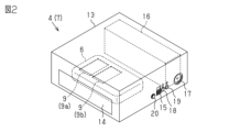
- 1 is a perspective view of a key storing device which is an example of a product.
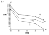
- 4 is a graph showing the relationship between the output voltage of a battery and the remaining charge amount.
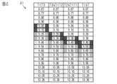
- 11 is a setting table used to set a determination threshold value.
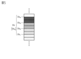
- FIG. 11 is an explanatory diagram of a plurality of determination thresholds that are set in stages.
- FIG. 2 is a schematic diagram of remote operation of a key receiving device by a terminal.
- FIG. 11 is a diagram showing the transmission of data used to notify the battery state.
- FIG. 11 is a diagram showing an example of a display of a remaining charge.
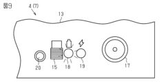
- FIG. 11 is a diagram showing an example of a display of a remaining charge.
- the target of use 2 includes a product 4 that is remotely operated by a user's terminal 3.
- the target of use 2 is, for example, a vehicle 5.
- Examples of the vehicle 5 include a shared car and a rental car.
- the product 4 is mounted on the vehicle 5 that is rented to a person.
- the product 4 is, for example, a key storage device 7 that stores an electronic key 6.
- the key storage device 7 is disposed inside the vehicle 5. It is preferable that the key storage device 7 is disposed in a place that is not visible to the public, for example, inside the dashboard, under the seat, under the feet of the seat, inside the trunk, or the like.
- the target of use 2 is equipped with a free key system 1 that operates the target of use 2 by remotely controlling a product 4 placed in the target of use 2 with a terminal 3.
- the free key system 1 operates the target of use 2, for example, by operating an electronic key system of a vehicle 5 with a key storage device 7.
- the electronic key system is, for example, a smart system or a wireless key system.
- the electronic key 6 includes an operation button 9 provided for remotely operating the vehicle 5.
- a plurality of operation buttons 9 may be provided.
- the operation buttons 9 include, for example, a lock button 9a for locking a door (e.g., a vehicle door) and an unlock button 9b for unlocking the door (e.g., a vehicle door). It is preferable that the operation button 9 is, for example, a push button.
- the electronic key 6 transmits, for example, radio waves in the UHF (Ultra High Frequency) band.
- UHF Ultra High Frequency
- the key storage device 7 is equipped with a drive mechanism 10 for mechanically operating the operation button 9 of the electronic key 6.
- the drive mechanism 10 mechanically operates the operation button 9 of the electronic key 6 by means of an actuator 11 such as a motor.
- the electronic key 6 transmits a signal corresponding to the operation button 9 operated by the drive mechanism 10, thereby causing the target of use 2 to operate based on the signal.
- the terminal 3 may be, for example, a high-function mobile phone, a wearable device, or a tablet device.
- the terminal 3 mechanically operates the operation button 9 of the electronic key 6 by operating the drive mechanism 10 via wireless communication.
- the drive mechanism 10 operates the unlock button 9b of the electronic key 6 to unlock the door.
- the drive mechanism 10 operates the lock button 9a of the electronic key 6 to lock the door.
- the key storage device 7 includes a housing 13 and a tray 14 in which the electronic key 6 is set.
- the tray 14 may be openable and closable relative to the housing 13, or may be fixed so as not to be openable and closable.
- the key storage device 7 includes, for example, a power switch 15 that switches the power supply of the key storage device 7 on and off.
- the power switch 15 is disposed, for example, on the side of the housing 13. When the power switch 15 is turned on, the key storage device 7 operates using a battery 16 housed in the housing 13 as a power source.
- the battery 16 is, for example, a secondary battery that can be used repeatedly by charging the battery 16.
- the key storage device 7 has, for example, a cable insertion port 17 for inserting a charging cable (not shown).
- the cable insertion port 17 is arranged, for example, on a side of the housing 13.
- an in-vehicle charging cable that supplies power from a cigarette lighter socket inside the vehicle is connected to the cable insertion port 17.
- the cable insertion port 17 may also be a USB cable that supplies power from a USB port.
- Multiple cable insertion ports 17 may be provided, for example, on multiple side surfaces of the housing 13.
- the key storage device 7 includes, for example, a first light-emitting unit 18 and a second light-emitting unit 19 for indicating the operating state of the key storage device 7.
- the first light-emitting unit 18 and the second light-emitting unit 19 are, for example, LEDs, and are disposed on the side of the housing 13.
- the first light-emitting unit 18 for example, notifies the remaining charge. Specifically, when the test button 20 provided on the side of the housing 13 is operated, the first light-emitting unit 18 emits light in a manner that corresponds to the remaining charge of the battery 16 in the key storage device 7. The first light-emitting unit 18 notifies the remaining charge by changing colors. Specifically, the first light-emitting unit 18 notifies when the remaining charge is "high”, when the remaining charge is "medium”, when the remaining charge is "low”, and when the remaining charge is "very low” by changing colors.
- the second light-emitting unit 19, for example, notifies the charging status.
- the second light-emitting unit 19 lights up when charging is in progress.
- the second light-emitting unit 19 lights up green when charging is in progress, lights up red when slow charging is in progress, and is turned off when not charging.
- the free key system 1 includes a device control unit 23 that controls the operation of the key storage device 7.
- the device control unit 23 authenticates the terminal 3 by a digital key function (hereinafter, referred to as a digital key system 22) that registers a digital key 24 in the terminal 3 to serve as a key for the key storage device 7.
- An application 25 required for operating the terminal 3 as a key for the key storage device 7 is registered in the terminal 3.
- the application 25 may be registered in the terminal 3 in advance, or may be downloaded from an external source.
- the terminal 3 is equipped with a terminal control unit 26 that controls the operation of the terminal 3.
- the terminal control unit 26 downloads a unique digital key 24 from an external source, thereby making the terminal 3 the key for the key storage device 7.
- the digital key 24 is generated, for example, at a center (not shown) that manages the digital key 24, and is distributed to the terminal 3 via network communication. It is preferable that the digital key 24 is, for example, a one-time key that is permitted to be used only once or for a certain period of time.
- the device control unit 23 includes a communication module 27 that communicates with the terminal 3.
- short-range wireless communication is used for communication between the terminal 3 and the communication module 27.
- the short-range wireless communication may be a personal area network (PAN) or short-range wireless communication.
- PAN personal area network
- Examples of personal area network communication include Bluetooth (registered trademark) communication, UWB (Ultra Wide Band) communication, and Wi-Fi (registered trademark) communication.
- Examples of Bluetooth communication include BLE (Bluetooth Low Energy).
- the device control unit 23 includes an authentication unit 28 that authenticates the digital key 24 of the terminal 3.
- the authentication unit 28 authenticates the validity of the digital key 24 by checking whether the digital key 24 obtained from the terminal 3 can be correctly decrypted.
- the authentication method for the digital key 24 is not limited to such an encryption key method, and may be, for example, an ID authentication method or a hash function method.
- the ID authentication method is, for example, an authentication method that compares a predetermined code with a response.
- the hash function method is, for example, an authentication method that uses a hash value.
- the digital key 24 is, for example, generated by encrypting it with a key corresponding to each individual device control unit 23.
- the authentication unit 28 wirelessly acquires the digital key 24 from the terminal 3, it authenticates the digital key 24.
- the authentication unit 28 authenticates the digital key 24 acquired from the terminal 3, if authentication is successful, it permits operation of the key storage device 7. This makes it possible to operate the vehicle 5 by remotely operating the electronic key 6 stored in the key storage device 7 from the terminal 3.
- the key receiving device 7 includes a voltage detection unit 30 that detects the output voltage of the battery 16.
- the voltage detection unit 30 includes a voltage dividing circuit 31 in which a first resistor R1 and a second resistor R2 are connected in series.
- the voltage dividing circuit 31 has the first resistor R1 connected to the battery 16 and the second resistor R2 connected to ground.
- a midpoint 32 of the voltage dividing circuit 31 is connected to an A/D terminal 33 of the device control unit 23.
- a capacitor 34 is connected to the voltage dividing circuit 31 to remove noise generated in the voltage dividing circuit 31.
- the A/D terminal 33 of the device control unit 23 inputs the divided voltage value of the analog signal generated at the midpoint 32 of the voltage divider circuit 31 as the current voltage value of the battery 16.
- the device control unit 23 then converts the divided voltage value of the analog signal input at the A/D terminal 33 into a digital signal, thereby acquiring it as a digital value of the output voltage. In this way, the device control unit 23 acquires the voltage at the midpoint 32 of the voltage divider circuit 31 as data on the output voltage of the battery 16.
- the free key system 1 includes a notification control device 36 that notifies the user of the battery status of the battery 16 that is the power source of the product 4 (in this example, the key storage device 7).
- the notification control device 36 compares the output voltage data acquired from the voltage detection unit 30 with a judgment threshold Vk, which is a measure of whether the output voltage is high or low, and notifies the user of the comparison result as the current battery status.
- the battery status notified to the user is, for example, the remaining charge of the battery 16.
- the judgment threshold Vk in this example is, for example, a remaining charge judgment threshold Vkx for judging the remaining charge.
- the judgment threshold Vk is set, for example, to a voltage value that is the minimum required to operate the actuator 11 at least once.
- FIG. 3 is a characteristic diagram showing the correlation between the output voltage [V] and the remaining charge [%] of the battery 16 in a plurality of temperature patterns. In this example, the relationship between the remaining charge and the actually measured output voltage is shown.
- the waveform when the temperature is the lowest is shown as "K1”
- the waveform when the temperature is the second lowest is shown as "K2”
- the waveform when the temperature is the third lowest is shown as "K3”
- the waveform when the temperature is the highest is shown as "K4".
- the temperatures when the waveforms K1 and K2 are, for example, below freezing point.
- the determination threshold Vk is set to a constant value when determining the remaining charge, if the output voltage of battery 16 changes due to a sudden change in temperature, the user notification of the battery status will also change suddenly, which may cause the user to feel uncomfortable.
- the key holding device 7 includes a temperature detection unit 38 that detects the temperature of the key holding device 7.
- the temperature detection unit 38 is, for example, a thermistor.
- the temperature detection unit 38 is preferably mounted on, for example, a board provided in the key holding device 7.
- the temperature detection unit 38 detects, for example, the temperature of the battery 16 of the key holding device 7.
- the temperature detection unit 38 outputs the detected temperature data to the device control unit 23.
- the notification control device 36 includes a data communication unit 39 that transmits data necessary for the remaining charge notification to the terminal 3.
- the data communication unit 39 is provided, for example, in the device control unit 23.
- the data communication unit 39 transmits, as data necessary for the remaining charge notification, for example, data on the output voltage detected by the voltage detection unit 30 (output voltage data) and temperature data detected by the temperature detection unit 38 from the communication module 27 to the terminal 3.
- the data communication unit 39 transmits, for example, the output voltage data and temperature data to the terminal 3 during communication in which the key storage device 7 is remotely operated by the terminal 3.
- the notification control device 36 includes a setting unit 40 that sets a judgment threshold Vk to be compared with the output voltage data.
- the setting unit 40 is provided, for example, in the terminal control unit 26.
- the output voltage of the battery 16 has a characteristic that the output changes in response to changes in the temperature of the surrounding environment, even if the remaining charge is the same, for example.
- the setting unit 40 in this example sets the judgment threshold Vk to be compared with the output voltage of the battery 16 having the aforementioned characteristic to a value corresponding to the current temperature, based on the temperature data from the temperature detection unit 38 that detects the temperature of the product 4.
- the setting unit 40 sets the judgment threshold Vk according to the temperature of the battery 16 by using a setting table 41 that associates the temperature of the battery 16 with the judgment threshold Vk.
- the temperature of the battery 16 is divided into a plurality of temperature ranges, and a predetermined judgment threshold Vk is set for each divided temperature range.
- the temperature of the battery 16 is divided into four temperature ranges: "T1 ⁇ T”, “T2 ⁇ T ⁇ T1", “T3 ⁇ T ⁇ T2", and "T ⁇ T3".
- a unique judgment threshold Vk is set for each temperature range.
- the setting unit 40 changes the judgment threshold Vk to a low value when the temperature of the product 4 is low, and changes the judgment threshold Vk to a high value when the temperature of the product 4 is high. For example, when the temperature "T" of the battery 16 satisfies the condition "T1 ⁇ T”, the judgment threshold Vk is set to a high value. On the other hand, when the temperature "T" of the battery 16 satisfies the condition "T ⁇ T3", the judgment threshold Vk is set to a low value.
- the judgment threshold Vk has a number of different values to notify the remaining charge in stages.
- the judgment threshold Vk has a first remaining charge judgment threshold Vk1 which is the boundary between the remaining charge switching from “high” to “medium”, a second remaining charge judgment threshold Vk2 which is the boundary between the remaining charge switching from “medium” to “low”, a third remaining charge judgment threshold Vk3 which is the boundary between the remaining charge switching from “low” to “very low”, and a fourth remaining charge judgment threshold Vk4 which is the boundary between the remaining charge switching from "very low” to “none".
- the setting unit 40 sets four judgment thresholds Vk according to temperature based on the current temperature of the battery 16.
- the notification control device 36 includes a notification processing unit 42 that notifies the user of the comparison result when comparing the output voltage of the battery 16 with the judgment threshold Vk as the current battery status.
- the notification processing unit 42 is provided, for example, in the terminal control unit 26.
- the notification processing unit 42 for example, causes the terminal 3 to execute notification of the battery status.
- the notification of the battery status is notification of the remaining charge of the battery 16. In this way, notification of the remaining charge is executed by the terminal 3.
- the notification processing unit 42 notifies the user of whether the remaining charge of the battery 16 is "high”, “medium”, “low”, “very low", or "none".
- the device control unit 23 causes the drive mechanism 10 to unlock the electronic key 6 based on the unlock request received from the terminal 3. Specifically, the device control unit 23 causes the drive mechanism 10 to mechanically press the unlock button 9b of the electronic key 6. This causes the electronic key 6 to transmit an unlock signal via UHF radio waves. The vehicle 5 unlocks the doors by receiving the unlock signal transmitted from the electronic key 6. This allows the user to enter the vehicle 5.
- the device control unit 23 sends an unlocking completion notification to the terminal 3 via the communication module 27.
- the terminal 3 displays, for example, on the screen of the terminal 3 that the doors have been unlocked. This allows the user to know that the doors of the vehicle 5 have been unlocked.
- the data communication unit 39 transmits output voltage data detected by the voltage detection unit 30 and temperature data detected by the temperature detection unit 38 to the terminal 3 via the communication module 27. It is preferable that the output voltage data and temperature data are transmitted to the terminal 3 simultaneously with, for example, the above-mentioned unlocking completion notification.
- the terminal control unit 26 When the terminal control unit 26 receives the output voltage data and temperature data transmitted from the key storage device 7, it notifies the remaining charge based on this data.
- the setting unit 40 for example, refers to the setting table 41 to confirm to which temperature range the acquired temperature data belongs, and sets the determination threshold value Vk used to determine the remaining charge.
- the first remaining charge determination threshold Vk1 to the fourth remaining charge determination threshold Vk4 are set as follows:
- the first remaining charge determination threshold Vk1 used to determine the boundary between "high to medium” remaining charge is set to a voltage between 9.96 to 10.06 [V].
- the second remaining charge determination threshold Vk2 used to determine the boundary between "medium to low” remaining charge is set to a value between 9.76 to 9.86 [V].
- the third remaining charge determination threshold Vk3 used to determine the boundary between "low to very low” remaining charge is set to a voltage between 9.56 to 9.66 [V].
- the fourth remaining charge determination threshold Vk4 used to determine the boundary between "very low to none” remaining charge is set to a voltage between 9.36 to 9.46 [V]. As described above, when the temperature of the key storage device 7 is "T1 ⁇ T", each judgment threshold Vk is set to a high value.
- the first remaining amount determination threshold Vk1 is set to a voltage between 9.86 and 9.96 [V]
- the second remaining amount determination threshold Vk2 is set to a value between 9.66 and 9.76 [V]
- the third remaining amount determination threshold Vk3 is set to a voltage between 9.46 and 9.56 [V]
- the fourth remaining amount determination threshold Vk4 is set to a voltage between 9.26 and 9.36 [V].
- each determination threshold Vk is set to a lower voltage than when the temperature is "T1 ⁇ T.”
- the first remaining amount determination threshold Vk1 is set to a voltage between 9.76 and 9.86 [V]
- the second remaining amount determination threshold Vk2 is set to a value between 9.56 and 9.66 [V]
- the third remaining amount determination threshold Vk3 is set to a voltage between 9.36 and 9.46 [V]
- the fourth remaining amount determination threshold Vk4 is set to a voltage between 9.16 and 9.26 [V].
- each determination threshold Vk is set to a lower voltage than when the temperature is "T2 ⁇ T ⁇ T1.”
- the first remaining amount determination threshold Vk1 is set to a voltage between 9.56 and 9.66 [V]
- the second remaining amount determination threshold Vk2 is set to a value between 9.36 and 9.46 [V]
- the third remaining amount determination threshold Vk3 is set to a voltage between 9.16 and 9.26 [V]
- the fourth remaining amount determination threshold Vk4 is set to a voltage between 8.96 and 9.06 [V].
- each determination threshold Vk is set to a lower voltage than when the temperature is "T3 ⁇ T ⁇ T2".
- the first remaining amount determination threshold Vk1 to the fourth remaining amount determination threshold Vk4 are changed to lower values as the temperature of the key storage device 7 decreases. In other words, even if the surrounding environment becomes cold, the optimal remaining amount determination threshold Vkx is set according to the low temperature. In this way, the first remaining amount determination threshold Vk1 to the fourth remaining amount determination threshold Vk4 are set to optimal values according to the current temperature of the key storage device 7.
- the notification processing unit 42 performs a remaining charge determination of the battery 16 using the determination threshold Vk set by the setting unit 40 and the output voltage data acquired from the key storage device 7. Specifically, the notification processing unit 42 performs a remaining charge determination of the battery 16 using the determination threshold Vk set from the setting table 41. If the output voltage exceeds the first remaining charge determination threshold Vk1, the notification processing unit 42 determines the remaining charge to be "high", and if the output voltage is a value between the first remaining charge determination threshold Vk1 and the second remaining charge determination threshold Vk2, the notification processing unit 42 determines the remaining charge to be "medium".
- the notification processing unit 42 determines the remaining charge to be "low”, if the output voltage is a value between the third remaining charge determination threshold Vk3 and the fourth remaining charge determination threshold Vk4, the notification processing unit 42 determines the remaining charge to be "very low”, and if the output voltage is equal to or less than the fourth remaining charge determination threshold Vk4, the notification processing unit 42 determines the remaining charge to be "none". The notification processing unit 42 then displays the remaining charge determination result on the screen of the terminal 3.
- the notification processing unit 42 preferably displays the remaining charge using, for example, a scale display 43.
- the scale display 43 is a display in which a picture representing the battery 16 is divided into four scales. The scale cells are filled with a number corresponding to the remaining charge, thereby visually notifying the user of whether the remaining charge is "high” to "no.” It is also preferable that the remaining charge "high” to "no" is displayed in a combination of different colors, for example.
- the remaining charge notification may be performed, for example, not only by the terminal 3 but also by the key storage device 7.
- the first light-emitting unit 18 is used.
- the first light-emitting unit 18 notifies the remaining charge by using different colors. Specifically, it emits "green” when the remaining charge is “high”, emits “yellow” when the remaining charge is “medium”, emits “orange” when the remaining charge is “low”, and emits "red” when the remaining charge is "very low”.
- the notification control device 36 is used in a product 4 that is remotely controlled by a user's terminal 3, and notifies the user of the battery status of the battery 16 that is the power source for the product 4.
- the setting unit 40 provided in the notification control device 36 sets the judgment threshold Vk, which is compared with the output voltage of the battery 16, whose output changes depending on the temperature change of the surrounding environment even with the same remaining charge, to a value corresponding to the current temperature based on the temperature data from the temperature detection unit 38 that detects the temperature of the product 4.
- the notification processing unit 42 provided in the notification control device 36 notifies the user of the comparison result when the output voltage of the battery 16 is compared with the judgment threshold Vk as the current battery status.
- the judgment threshold Vk is a remaining charge judgment threshold Vkx for judging the remaining charge.
- the battery state notified to the user is the remaining charge of the battery 16. With this configuration, the remaining charge of the battery 16 of the product 4 can be notified to the user without causing any discomfort.
- the judgment threshold Vk has multiple different values to display the remaining charge in stages. With this configuration, the remaining charge can be notified to the user in stages. This further contributes to reducing discomfort when the remaining charge is notified.
- the setting unit 40 changes the judgment threshold Vk to a low value when the temperature of the product 4 is low, and changes the judgment threshold Vk to a high value when the temperature of the product 4 is high.
- the notification processing unit 42 causes the terminal 3 to notify the battery state. According to this configuration, it becomes possible to check the battery state on the terminal 3, which contributes to improving convenience.
- the product 4 is a key storage device 7 that operates an object of use 2 in which the product 4 is mounted by selectively operating an operation button 9 of an electronic key 6 stored inside a housing 13 with an actuator 11. With this configuration, the battery status of the battery 16 of the key storage device 7 can be notified to the user without being affected by temperature changes in the surrounding environment.
- the judgment threshold Vk is set to the minimum voltage value required to operate the actuator 11 at least once. With this configuration, it is possible to notify the user that the actuator 11 is in a state where it is difficult to operate with the current remaining charge.
- the current battery state notified by the notification processing unit 42 may include information encouraging early charging. For example, when the battery level falls below a predetermined remaining charge determination threshold Vkx, the user may be notified of information encouraging early charging. This notification may be implemented, for example, by a message, icon display, or voice notification via the application 25. This allows the user to quickly carry out the charging process.
- the temperature detection unit 38 does not necessarily have to be mounted on the circuit board of the product 4.
- the temperature detection unit 38 may be, for example, a sensor provided in the battery 16.
- the temperature detection unit 38 may be a sensor that detects the temperature in a room in which the product 4 is placed. In other words, the temperature detection unit 38 may be a separate member from the product 4.
- the determination threshold value Vk is not limited to multiple values, and may be one.
- the method for determining the determination threshold value Vk is not limited to the method using the setting table 41, and may be, for example, a method using a calculation formula.
- notification of the comparison result may be performed by both the terminal 3 and the key storage device 7. Also, notification of the comparison result may be performed by a display device provided in the target of use 2. Examples of the display device include a display of a car navigation system, a multi-information display, a meter, etc.
- the product 4 is not limited to the key storage device 7 and may be any device that can be remotely controlled by the terminal 3.
- the notification control device 36 may be, for example, a device that monitors abnormalities in voltage changes of the battery 16. For example, the notification control device 36 may monitor the amount of change per unit time of the output voltage, and if the amount of change is an abnormal value, may notify that fact.
- a smart system includes, for example, a system that performs wireless authentication of the electronic key 6 when communication from the target user 2 is triggered.
- a wireless key system includes, for example, a system that performs wireless authentication when communication from the electronic key 6 is triggered.
- the target of use 2 is not limited to a vehicle 5 and may be another device or equipment.
- the data communication unit 39, the setting unit 40, and the notification processing unit 42 may be configured as follows: [1] one or more processors that operate according to a computer program (software), or [2] a combination of such a processor and one or more dedicated hardware circuits such as an application specific integrated circuit (ASIC) that executes at least some of the various processes.
- the processor includes a CPU and memory such as RAM and ROM, and the memory stores program code or instructions that are configured to cause the CPU to execute the processes.
- the memory (computer-readable medium) includes any available medium that can be accessed by a general-purpose or dedicated computer. Alternatively, instead of a computer including the processor, a processing circuit configured by one or more dedicated hardware circuits that execute all of the various processes may be used.
- the data communication unit 39, the setting unit 40, and the notification processing unit 42 may be configured from independent processors, or may be constructed from a processor with some of its functions shared. In this way, the data communication unit 39, the setting unit 40, and the notification processing unit 42 are not limited to being independent functional blocks, and may be configured from a single functional block, or may be configured from a functional block with some functions shared.
- a system (1) one or more processors (39, 40, 42); one or more memories storing a plurality of instructions that, when executed by the one or more processors, cause the one or more processors to perform a plurality of operations, the plurality of operations comprising: Obtaining temperature measurements from a temperature detector (38) for a battery (16) of a product (4) remotely controlled by a user terminal (3); obtaining an output voltage measurement for the battery from a voltage detector (30); setting one or more remaining charge determination thresholds (Vk, Vk1 to Vk4) for classifying the remaining charge of the battery into a plurality of levels based on the acquired temperature measurement value; comparing the acquired output voltage measurement value with the one or more remaining capacity determination thresholds that have been set; notifying a user of the result of the comparison as the current remaining charge of the battery using at least
- the system includes the product and the terminal,
- the product is a housing (13) for accommodating an electronic key (6) for an object of use (2, 5) in which the product is mounted, the electronic key having one or more operating buttons (9 a, 9 b); a drive mechanism (10) configured to mechanically operate the one or more operation buttons of the electronic key;
- the system of claim 1 or 2 wherein the terminal is configured to transmit a wireless signal to the driving mechanism to cause the driving mechanism (10) to mechanically operate the one or more operating buttons of the electronic key.
Landscapes
- Physics & Mathematics (AREA)
- General Physics & Mathematics (AREA)
- Engineering & Computer Science (AREA)
- Computer Networks & Wireless Communication (AREA)
- Charge And Discharge Circuits For Batteries Or The Like (AREA)
- Secondary Cells (AREA)
- Tests Of Electric Status Of Batteries (AREA)
- Selective Calling Equipment (AREA)
Abstract
通知制御装置(36)は、ユーザの端末(3)によって遠隔操作される製品(4)に使用され、製品(4)の電源である電池(16)の電池状態をユーザに通知する。設定部(40)は、製品(4)の温度を検出する温度検出部(38)の温度データに基づき、同じ充電残量でも周囲環境の温度変化によって出力が変化する電池(16)の出力電圧と比較される判定閾値(残量判定閾値)を、現在の温度に対応する値に設定する。通知処理部(42)は、電池(16)の出力電圧と判定閾値とを比較したときの比較結果を、現在の電池状態としてユーザに通知する。
Description
本開示は、電池状態を通知する通知制御装置、通知制御方法、及びプログラムに関する。
従来、特許文献1に開示されるように、二次電池の劣化の抑制に効果的な情報を示す電子機器が周知である。特許文献1の場合、電子機器に設けられた制御部は、二次電池の充電について、二次電池の複数の劣化条件をそれぞれ満たしているか否かを判別する。そして、制御部は、満たしていると判別された劣化条件に係る内容を指定して出力部に出力させる。
二次電池の充電についての通知としては、前述のような充電の劣化条件に係る内容の通知に限らず、例えば、二次電池の充電残量の通知も想定される。ところで、電池の出力電圧は、充電残量が一定であっても温度によって変化する。このため、充電残量が一定であっても、温度の急変が生じてしまうと電池の出力電圧の急変も併せて生じ得るので、ユーザへの現在の電池状態の通知も急変してしまう。よって、ユーザにとっては、通知に違和感を持つ可能性がある。
本開示の一態様による通知制御装置は、ユーザの端末によって遠隔操作される製品に使用され、前記製品の電源である電池の電池状態をユーザに通知する装置であって、前記製品の温度を検出する温度検出部の温度データに基づき、同じ充電残量でも周囲環境の温度変化によって出力が変化する前記電池の出力電圧と比較される判定閾値を、現在の温度に対応する値に設定する設定部と、前記出力電圧と前記判定閾値とを比較したときの比較結果を、現在の前記電池状態としてユーザに通知する通知処理部と、を備えた。
本開示の一態様による通知制御方法は、ユーザの端末によって遠隔操作される製品に使用され、前記製品の電源である電池の電池状態をユーザに通知する方法であって、前記製品の温度を温度検出部で検出するステップと、前記電池の出力電圧を電圧検出部で検出するステップと、前記温度検出部によって検出された温度データに基づき、同じ充電残量でも周囲環境の温度変化によって出力が変化する前記出力電圧と比較される判定閾値を、現在の温度に対応する値に設定するステップと、前記電圧検出部によって検出された前記出力電圧と前記判定閾値とを比較したときの比較結果を、現在の前記電池状態として、前記端末及び前記製品の少なくとも一方を用いてユーザに通知するステップと、を備えた。
本開示の一態様によるプログラムは、ユーザの端末によって遠隔操作される製品に使用され、前記製品の電源である電池の電池状態をユーザに通知するコンピュータに、前記製品の温度を検出する温度検出部の温度データに基づき、同じ充電残量でも周囲環境の温度変化によって出力が変化する前記電池の出力電圧と比較される判定閾値を、現在の温度に対応する値に設定することと、前記出力電圧と前記判定閾値とを比較したときの比較結果を、現在の前記電池状態としてユーザに通知することと、を実行させる。
本開示の一態様によれば、電池状態の通知に違和感を生じ難くすることができる。
以下、本開示の一実施形態を説明する。
(フリーキーシステム1)
図1に示すように、利用対象2は、ユーザの端末3によって遠隔操作される製品4を備える。利用対象2は、例えば、車両5である。車両5は、例えば、シェアリングカーやレンタカーなどが挙げられる。このように、製品4は、人に貸し出す車両5に搭載される。製品4は、例えば、電子キー6を収容するキー収容装置7である。キー収容装置7は、車両5の室内に配置される。キー収容装置7は、例えば、ダッシュボードの内部、シートの下、座席の足下、トランクの内部など、人目に付かない場所に配置されることが好ましい。
(フリーキーシステム1)
図1に示すように、利用対象2は、ユーザの端末3によって遠隔操作される製品4を備える。利用対象2は、例えば、車両5である。車両5は、例えば、シェアリングカーやレンタカーなどが挙げられる。このように、製品4は、人に貸し出す車両5に搭載される。製品4は、例えば、電子キー6を収容するキー収容装置7である。キー収容装置7は、車両5の室内に配置される。キー収容装置7は、例えば、ダッシュボードの内部、シートの下、座席の足下、トランクの内部など、人目に付かない場所に配置されることが好ましい。
利用対象2は、利用対象2に配置された製品4を端末3で遠隔操作して利用対象2を操作するフリーキーシステム1を備える。フリーキーシステム1は、例えば、キー収容装置7によって車両5の電子キーシステムを操作することにより、利用対象2を動作させる。電子キーシステムは、例えば、スマートシステムやワイヤレスキーシステムである。
電子キー6は、車両5の遠隔操作のために設けられた操作ボタン9を備える。操作ボタン9は、例えば、複数設けられる。本例の場合、操作ボタン9は、例えば、ドア(例えば、車両ドア)をロックするためのロックボタン9aと、ドア(例えば、車両ドア)をアンロックするためのアンロックボタン9bと、を含む。操作ボタン9は、例えば、プッシュボタンであることが好ましい。電子キー6は、例えば、UHF(Ultra High Frequency)帯の電波を送信する。
キー収容装置7は、電子キー6の操作ボタン9を機械的に操作するための駆動機構10を備える。駆動機構10は、例えば、モータ等のアクチュエータ11によって、電子キー6の操作ボタン9を機械的に操作する。電子キー6は、駆動機構10によって操作された操作ボタン9に応じた信号を送信することにより、利用対象2を信号に基づいて動作させる。
端末3は、例えば、高機能携帯電話、ウェアラブル端末、タブレット端末などが挙げられる。端末3は、駆動機構10を無線通信により動作させることにより、電子キー6の操作ボタン9を機械的に操作する。例えば、端末3で解錠操作が実行されると、駆動機構10によって電子キー6のアンロックボタン9bが操作されることにより、ドアが解錠される。また、端末3で施錠操作が実行されると、駆動機構10によって電子キー6のロックボタン9aが操作されることにより、ドアが施錠される。
(キー収容装置7)
図2に示すように、キー収容装置7は、ハウジング13と、電子キー6がセットされたトレイ14と、を備える。トレイ14は、ハウジング13に開閉可能であってもよいし、開閉不可能に固定されていてもよい。
図2に示すように、キー収容装置7は、ハウジング13と、電子キー6がセットされたトレイ14と、を備える。トレイ14は、ハウジング13に開閉可能であってもよいし、開閉不可能に固定されていてもよい。
キー収容装置7は、例えば、キー収容装置7の電源のオンオフを切り替える電源スイッチ15を備える。電源スイッチ15は、例えば、ハウジング13の側面に配置されている。キー収容装置7は、電源スイッチ15がオンされると、ハウジング13に収容された電池16を電源として動作させる。電池16は、例えば、電池16を充電することにより繰り返し使用可能な二次電池である。
キー収容装置7は、例えば、充電ケーブル(図示略)を挿入するためのケーブル挿入口17を備える。ケーブル挿入口17は、例えば、ハウジング13の側面に配置されている。ケーブル挿入口17には、例えば、車内のシガーソケットから電力を供給する車内用充電ケーブルが接続される。また、ケーブル挿入口17は、USBポートから電力を供給するUSBケーブルでもよい。複数のケーブル挿入口17は、例えば、ハウジング13の複数の側面にそれぞれ設けられてもよい。
キー収容装置7は、例えば、キー収容装置7の動作状態を通知するための第1発光部18及び第2発光部19を備える。第1発光部18及び第2発光部19は、例えば、LEDであって、ハウジング13の側面に配置されている。
第1発光部18は、例えば、充電残量の通知を実行する。具体的には、ハウジング13の側面に設けられたテストボタン20が操作されたとき、第1発光部18は、キー収容装置7の電池16の充電残量に応じた態様で発光する。第1発光部18は、色の違いによって充電残量を通知する。具体的には、第1発光部18は、充電残量が「高」のときと、充電残量が「中」のときと、充電残量が「低」のときと、充電残量が「極低」のときとを、色の違いによって通知する。
第2発光部19は、例えば、充電状態の通知を実行する。第2発光部19は、例えば、充電が行われている場合に点灯する。具体的には、第2発光部19は、充電中の場合、緑色で点灯し、低速充電中の場合、赤色で点灯し、充電されていない場合、消灯する。
(デジタルキーシステム22)
図1に示す通り、フリーキーシステム1は、キー収容装置7の動作を制御する装置制御部23を備える。装置制御部23は、端末3にデジタルキー24を登録してキー収容装置7のキーとするデジタルキー機能(以降、デジタルキーシステム22と記す)によって、端末3を認証する。端末3は、端末3をキー収容装置7のキーとして動作させるのに必要なアプリケーション25が登録されている。アプリケーション25は、予め端末3に登録されていてもよいし、或いは、外部からダウンロードされてもよい。
図1に示す通り、フリーキーシステム1は、キー収容装置7の動作を制御する装置制御部23を備える。装置制御部23は、端末3にデジタルキー24を登録してキー収容装置7のキーとするデジタルキー機能(以降、デジタルキーシステム22と記す)によって、端末3を認証する。端末3は、端末3をキー収容装置7のキーとして動作させるのに必要なアプリケーション25が登録されている。アプリケーション25は、予め端末3に登録されていてもよいし、或いは、外部からダウンロードされてもよい。
端末3は、端末3の動作を制御する端末制御部26を備える。端末制御部26は、固有のデジタルキー24を外部からダウンロードすることにより、端末3をキー収容装置7のキーとする。デジタルキー24は、例えば、デジタルキー24を管理するセンター(図示略)などで生成されるとともに、ネットワーク通信を介して、端末3に配信される。デジタルキー24は、例えば、使用が一度または一定期間のみ許可されたワンタイムキーであることが好ましい。
装置制御部23は、端末3との通信を実行する通信モジュール27を備える。端末3及び通信モジュール27の間の通信は、例えば、近距離無線通信が使用される。近距離無線通信は、PAN(Personal Area Network:パーソナルエリアネットワーク)であってもよいし、短距離無線通信であってもよい。パーソナルエリアネットワーク通信は、例えば、ブルートゥース(Bluetooth:登録商標)通信、UWB(Ultra Wide Band)通信、Wi-Fi(登録商標)通信などが挙げられる。ブルートゥース通信は、BLE(Bluetooth Low Energy)などが挙げられる。
装置制御部23は、端末3のデジタルキー24の認証を実行する認証部28を備える。認証部28は、端末3から取得したデジタルキー24を正しく復号できるか否かを確認することにより、デジタルキー24の正当性を認証する。なお、デジタルキー24の認証方式は、このような暗号鍵方式に限定されず、例えば、ID認証方式やハッシュ関数方式などを用いてもよい。ID認証方式は、例えば、所定コードと回答とを照合する認証である。ハッシュ関数方式は、例えば、ハッシュ値を用いた認証方式である。デジタルキー24は、例えば、個々の装置制御部23に応じた鍵で暗号化されて生成される。
認証部28は、端末3から無線によってデジタルキー24を取得すると、デジタルキー24を認証する。認証部28は、端末3から取得したデジタルキー24を認証したとき、認証が成立すると、キー収容装置7の動作を許可する。これにより、キー収容装置7に収容された電子キー6を端末3で遠隔操作することにより、車両5を動作させることが可能となる。
(電圧検出部30)
図1に示す通り、キー収容装置7は、電池16の出力電圧を検出する電圧検出部30を備える。電圧検出部30は、第1抵抗R1及び第2抵抗R2が直列に接続された分圧回路31を備える。分圧回路31は、第1抵抗R1が電池16に接続されるとともに、第2抵抗R2がグランドに接続されている。分圧回路31の中点32は、装置制御部23のA/D端子33に接続されている。分圧回路31には、分圧回路31に発生するノイズを除去するためのコンデンサ34が接続されている。
図1に示す通り、キー収容装置7は、電池16の出力電圧を検出する電圧検出部30を備える。電圧検出部30は、第1抵抗R1及び第2抵抗R2が直列に接続された分圧回路31を備える。分圧回路31は、第1抵抗R1が電池16に接続されるとともに、第2抵抗R2がグランドに接続されている。分圧回路31の中点32は、装置制御部23のA/D端子33に接続されている。分圧回路31には、分圧回路31に発生するノイズを除去するためのコンデンサ34が接続されている。
装置制御部23のA/D端子33は、分圧回路31の中点32に生成されるアナログ信号の分圧値を電池16の現在の電圧値として入力する。そして、装置制御部23は、A/D端子33で入力したアナログ信号の分圧値をデジタル信号に変換することにより、出力電圧のデジタル値として取得する。このようにして、装置制御部23は、分圧回路31の中点32の電圧を電池16の出力電圧のデータとして取得する。
(通知制御装置36)
図1に示す通り、フリーキーシステム1は、製品4(本例は、キー収容装置7)の電源である電池16の電池状態をユーザに通知する通知制御装置36を備える。本例の場合、通知制御装置36は、電圧検出部30から取得した出力電圧のデータと、出力電圧の高低の尺度である判定閾値Vkと、を比較するとともに、その比較結果を現在の電池状態としてユーザに通知する。ユーザに通知される電池状態は、例えば、電池16の充電残量である。本例の判定閾値Vkは、例えば、充電残量を判定するための残量判定閾値Vkxである。判定閾値Vkは、例えば、アクチュエータ11を少なくとも1回動作させるのに最低限必要な電圧値に設定されている。
図1に示す通り、フリーキーシステム1は、製品4(本例は、キー収容装置7)の電源である電池16の電池状態をユーザに通知する通知制御装置36を備える。本例の場合、通知制御装置36は、電圧検出部30から取得した出力電圧のデータと、出力電圧の高低の尺度である判定閾値Vkと、を比較するとともに、その比較結果を現在の電池状態としてユーザに通知する。ユーザに通知される電池状態は、例えば、電池16の充電残量である。本例の判定閾値Vkは、例えば、充電残量を判定するための残量判定閾値Vkxである。判定閾値Vkは、例えば、アクチュエータ11を少なくとも1回動作させるのに最低限必要な電圧値に設定されている。
(低温環境での物理現象)
図3は、複数の温度パターンにおける、電池16の出力電圧[V]と充電残量[%]との相関関係を示す特性図である。本例の場合、実測された出力電圧に対する充電残量の関係が示されている。図3の場合、例えば、最も温度が低いときの波形を「K1」で示し、2番目に温度が低いときの波形を「K2」で示し、3番目に温度が低いときの波形を「K3」で示し、最も温度が高いときの波形を「K4」で示す。波形K1、K2のときの温度は、例えば、氷点下である。
図3は、複数の温度パターンにおける、電池16の出力電圧[V]と充電残量[%]との相関関係を示す特性図である。本例の場合、実測された出力電圧に対する充電残量の関係が示されている。図3の場合、例えば、最も温度が低いときの波形を「K1」で示し、2番目に温度が低いときの波形を「K2」で示し、3番目に温度が低いときの波形を「K3」で示し、最も温度が高いときの波形を「K4」で示す。波形K1、K2のときの温度は、例えば、氷点下である。
図3に示す通り、周囲環境の温度が低いほど、出力電圧が低い値として出力されることが分かる。これは、仮に電池16の充電残量が一定でも、温度が低くなると電池16の内部抵抗が上昇するため、電池16の出力電圧が低くなってしまうからである。このため、充電残量を判定する場合に、判定閾値Vkを一定値に設定してしまうと、温度急変により電池16の出力電圧が変化した場合に、それに伴って電池状態のユーザ通知が急変してしまうため、ユーザが違和感を持つ可能性があった。
(充電残量通知の精度を高める対策)
図1に示す通り、キー収容装置7は、キー収容装置7の温度を検出する温度検出部38を備える。温度検出部38は、例えば、サーミスタである。温度検出部38は、例えば、キー収容装置7に設けられた基板に実装されていることが好ましい。温度検出部38は、例えば、キー収容装置7の電池16の温度を検出する。温度検出部38は、検出した温度データを、装置制御部23に出力する。
図1に示す通り、キー収容装置7は、キー収容装置7の温度を検出する温度検出部38を備える。温度検出部38は、例えば、サーミスタである。温度検出部38は、例えば、キー収容装置7に設けられた基板に実装されていることが好ましい。温度検出部38は、例えば、キー収容装置7の電池16の温度を検出する。温度検出部38は、検出した温度データを、装置制御部23に出力する。
通知制御装置36は、充電残量通知に必要なデータを端末3に送信するデータ通信部39を備える。データ通信部39は、例えば、装置制御部23に設けられている。データ通信部39は、充電残量通知に必要なデータとして、例えば、電圧検出部30によって検出された出力電圧のデータ(出力電圧データ)と、温度検出部38によって検出された温度データと、を通信モジュール27から端末3に送信する。データ通信部39は、例えば、端末3でキー収容装置7が遠隔操作される通信時に、端末3に出力電圧データ及び温度データを送信する。
通知制御装置36は、出力電圧データと比較される判定閾値Vkを設定する設定部40を備える。設定部40は、例えば、端末制御部26に設けられている。電池16の出力電圧は、例えば、充電残量が同じであっても、周囲環境の温度変化に応じて出力が変化する特性を有する。本例の設定部40は、前述の特性を有する電池16の出力電圧と比較する判定閾値Vkを、製品4の温度を検出する温度検出部38の温度データに基づき、現在の温度に対応する値に設定する。
図4に示すように、設定部40は、電池16の温度と判定閾値Vkとを対応付けた設定テーブル41を用いることにより、電池16の温度に応じた判定閾値Vkを設定する。設定テーブル41は、例えば、電池16の温度が複数の温度領域に区分されるとともに、区分された温度領域ごとに所定の判定閾値Vkが設定されている。本例の場合、電池16の温度を「T」とし、「T3<T2<T1」とした場合、電池16の温度は、「T1≦T」、「T2≦T<T1」、「T3≦T<T2」、及び「T<T3」の4つの温度領域に区分されている。そして、各温度領域には、固有の判定閾値Vkが設定されている。
設定部40は、製品4の温度が低い場合には、判定閾値Vkを低い値に変更し、製品4の温度が高い場合には、判定閾値Vkを高い値に変更する。例えば、電池16の温度「T」が「T1≦T」の条件を満たす場合、判定閾値Vkは、高い値に設定される。一方、電池16の温度「T」が「T<T3」の条件を満たす場合、判定閾値Vkは、低い値に設定される。
図5に示すように、判定閾値Vkは、充電残量を段階的に通知するために複数の異なる値を有する。本例の場合、判定閾値Vkは、充電残量が「高」→「中」への切り替わりの境目となる第1残量判定閾値Vk1と、充電残量が「中」→「低」への切り替わりの境目となる第2残量判定閾値Vk2と、充電残量が「低」→「極低」への切り替わりの境目となる第3残量判定閾値Vk3と、充電残量が「極低」→「無し」への切り替わりの境目となる第4残量判定閾値Vk4と、を有する。設定部40は、電池16の現状温度に基づき、温度に応じた4つの判定閾値Vkを設定する。
図1に示す通り、通知制御装置36は、電池16の出力電圧と判定閾値Vkとを比較したときの比較結果を、現在の電池状態としてユーザに通知する通知処理部42を備える。通知処理部42は、例えば、端末制御部26に設けられている。通知処理部42は、例えば、電池状態の通知を端末3に実行させる。電池状態の通知は、電池16の充電残量の通知である。このように、充電残量の通知は、端末3で実行される。通知処理部42は、電池16の充電残量が「高」、「中」、「低」、「極低」、「無し」のいずれであるのかをユーザに通知する。
次に、本実施形態の作用について説明する。
(キー収容装置1の動作)
図6に示すように、車両5のドアを解錠するときには、端末3でアプリケーション25を立ち上げるとともに、このときに端末3の画面に表示される解錠ボタンを操作する。端末3で解錠ボタンが操作されたとき、端末3は、解錠要求を近距離無線通信によってキー収容装置7に送信する。キー収容装置7は、デジタルキー24の認証が済んでいる端末3から送信された解錠要求を通信モジュール27で受信すると、この解錠要求に従って、電子キー6のアンロック操作を実行する。
(キー収容装置1の動作)
図6に示すように、車両5のドアを解錠するときには、端末3でアプリケーション25を立ち上げるとともに、このときに端末3の画面に表示される解錠ボタンを操作する。端末3で解錠ボタンが操作されたとき、端末3は、解錠要求を近距離無線通信によってキー収容装置7に送信する。キー収容装置7は、デジタルキー24の認証が済んでいる端末3から送信された解錠要求を通信モジュール27で受信すると、この解錠要求に従って、電子キー6のアンロック操作を実行する。
装置制御部23は、端末3から受信した解錠要求に基づき、駆動機構10に電子キー6をアンロック操作させる。具体的には、装置制御部23は、駆動機構10に電子キー6のアンロックボタン9bを機械的に押下させる。これにより、電子キー6から解錠信号がUHF帯の電波で送信される。車両5は、電子キー6から送信された解錠信号を受信することにより、ドアを解錠する。よって、ユーザは車両5に乗車可能になる。
装置制御部23は、駆動機構10による電子キー6に対してのアンロック操作が完了すると、通信モジュール27によって解錠完了通知を端末3に送信する。端末3は、この解錠完了通知を受信すると、例えば、端末3の画面に、ドアがアンロックされたことを表示する。よって、ユーザは、車両5のドアがアンロックされたことを知ることが可能となる。
なお、車両5のドアを施錠するときの動作は、ドアを解錠するときの動作とは逆であるが、基本的には同様である。すなわち、ドアの施錠時には、駆動機構10がドアの解錠時と逆方向に動作するだけである。よって、ドアの施錠時の動作については、説明を省略する。
(充電残量通知の動作)
図7に示すように、データ通信部39は、キー収容装置7が端末3によって遠隔操作されたとき、電圧検出部30によって検出された出力電圧データと、温度検出部38によって検出された温度データとを、通信モジュール27を介して端末3に送信する。出力電圧データ及び温度データは、例えば、前述の解錠完了通知と同時に端末3に送信されることが好ましい。
図7に示すように、データ通信部39は、キー収容装置7が端末3によって遠隔操作されたとき、電圧検出部30によって検出された出力電圧データと、温度検出部38によって検出された温度データとを、通信モジュール27を介して端末3に送信する。出力電圧データ及び温度データは、例えば、前述の解錠完了通知と同時に端末3に送信されることが好ましい。
端末制御部26は、キー収容装置7から送信された出力電圧データ及び温度データを受信すると、これらデータに基づいて充電残量の通知を実行する。本例の場合、設定部40は、例えば、設定テーブル41を参照することにより、取得した温度データがどこの温度領域に属するのかを確認することにより、充電残量の判定に使用する判定閾値Vkを設定する。
図4に示す通り、キー収容装置7の温度「T」が「T1≦T」の場合、第1残量判定閾値Vk1~第4残量判定閾値Vk4は、以下のように設定される。充電残量の「高~中」の境界の判定に使用される第1残量判定閾値Vk1は、9.96~10.06[V]の間の電圧に設定される。充電残量が「中~低」の境界の判定に使用される第2残量判定閾値Vk2は、9.76~9.86[V]の間の値に設定される。充電残量が「少~極低」の境界の判定に使用される第3残量判定閾値Vk3は、9.56~9.66[V]の間の電圧に設定される。充電残量が「極低~無し」の境界の判定に使用される第4残量判定閾値Vk4は、9.36~9.46[V]の間の電圧に設定される。以上のように、キー収容装置7の温度が「T1≦T」の場合、各判定閾値Vkは、高い値に設定される。
キー収容装置7の温度「T」が「T2≦T<T1(なお、T2<T1)」の場合は、第1残量判定閾値Vk1が9.86~9.96[V]の間の電圧に設定され、第2残量判定閾値Vk2が9.66~9.76[V]の間の値に設定され、第3残量判定閾値Vk3が9.46~9.56[V]の間の電圧に設定され、第4残量判定閾値Vk4が9.26~9.36[V]の間の電圧に設定される。以上のように、キー収容装置7の温度が「T2≦T<T1」のときは、温度が「T1≦T」のときよりも、各判定閾値Vkが低い電圧に設定される。
キー収容装置7の温度「T」が「T3≦T<T2(なお、T3<T2)」の場合は、第1残量判定閾値Vk1が9.76~9.86[V]の間の電圧に設定され、第2残量判定閾値Vk2が9.56~9.66[V]の間の値に設定され、第3残量判定閾値Vk3が9.36~9.46[V]の間の電圧に設定され、第4残量判定閾値Vk4が9.16~9.26[V]の間の電圧に設定される。以上のように、キー収容装置7の温度が「T3≦T<T2」のときは、温度が「T2≦T<T1」のときよりも、各判定閾値Vkが低い電圧に設定される。
キー収容装置7の温度「T」が「T<T3」の場合は、第1残量判定閾値Vk1が9.56~9.66[V]の間の電圧に設定され、第2残量判定閾値Vk2が9.36~9.46[V]の間の値に設定され、第3残量判定閾値Vk3が9.16~9.26[V]の間の電圧に設定され、第4残量判定閾値Vk4が8.96~9.06[V]の間の電圧に設定される。以上のように、キー収容装置7の温度が「T<T3」のときは、温度が「T3≦T<T2」のときよりも、各判定閾値Vkが低い電圧に設定される。
以上のように、第1残量判定閾値Vk1~第4残量判定閾値Vk4は、キー収容装置7の温度が低い程、低い値に変更される。すなわち、周囲環境が低温になっても、低温に応じた最適な残量判定閾値Vkxが設定される。このように、第1残量判定閾値Vk1~第4残量判定閾値Vk4は、キー収容装置7の現在温度に応じて最適な値に設定される。
通知処理部42は、設定部40によって設定された判定閾値Vkと、キー収容装置7から取得した出力電圧データとを用いて、電池16の残量判定を実行する。具体的には、通知処理部42は、設定テーブル41から設定された判定閾値Vkを用いて、電池16の残量判定を実行する。通知処理部42は、出力電圧が第1残量判定閾値Vk1を超える場合、充電残量を「高」と判定し、出力電圧が第1残量判定閾値Vk1~第2残量判定閾値Vk2の間の値の場合、充電残量を「中」と判定する。通知処理部42は、出力電圧が第2残量判定閾値Vk2~第3残量判定閾値Vk3の間の値の場合、充電残量を「低」と判定し、出力電圧が第3残量判定閾値Vk3~第4残量判定閾値Vk4の間の値の場合、充電残量を「極低」と判定し、出力電圧が第4残量判定閾値Vk4以下の場合、充電残量を「無し」と判定する。そして、通知処理部42は、この充電残量の判定結果を端末3の画面に表示する。
(充電残量の具体的な通知)
図8に示すように、通知処理部42は、例えば、目盛り表示43による充電残量表示を実行することが好ましい。例えば、目盛り表示43は、電池16を表す絵を4つの目盛りに分割した表示体である。そして、目盛セルが充電残量に応じた個数で塗りつぶされた表示によって、「高~無し」のいずれの充電残量であるのかがユーザに視覚通知される。また、充電残量の「高~無し」は、例えば、色の違いも組み合わせて表示されることが好ましい。
図8に示すように、通知処理部42は、例えば、目盛り表示43による充電残量表示を実行することが好ましい。例えば、目盛り表示43は、電池16を表す絵を4つの目盛りに分割した表示体である。そして、目盛セルが充電残量に応じた個数で塗りつぶされた表示によって、「高~無し」のいずれの充電残量であるのかがユーザに視覚通知される。また、充電残量の「高~無し」は、例えば、色の違いも組み合わせて表示されることが好ましい。
また、図9に示すように、充電残量通知は、例えば、端末3で実行することに限らず、キー収容装置7で実行されてもよい。キー収容装置7で充電残量通知を実行する場合、第1発光部18を使用する。第1発光部18は、充電残量を色の違いによって通知する。具体的には、充電残量が「高」のとき「緑」で発光し、充電残量が「中」のとき「黄」で発光し、充電残量が「低」のとき「橙」で発光し、充電残量が「極低」のとき「赤」で発光する。
(実施形態の効果)
上記実施形態の通知制御装置36(通知制御方法)によれば、以下のような効果を得ることができる。
上記実施形態の通知制御装置36(通知制御方法)によれば、以下のような効果を得ることができる。
(1)通知制御装置36は、ユーザの端末3によって遠隔操作される製品4に使用され、製品4の電源である電池16の電池状態をユーザに通知する。通知制御装置36が備える設定部40は、製品4の温度を検出する温度検出部38の温度データに基づき、同じ充電残量でも周囲環境の温度変化によって出力が変化する電池16の出力電圧と比較される判定閾値Vkを、現在の温度に対応する値に設定する。通知制御装置36が備える通知処理部42は、電池16の出力電圧と判定閾値Vkとを比較したときの比較結果を、現在の電池状態としてユーザに通知する。
本構成によれば、電池16の出力電圧と判定閾値Vkとを比較して電池状態を監視する場合に、製品4の現在の温度に基づいて最適な判定閾値Vkを設定することが可能となる。このため、現在の製品4の温度に応じて設定された最適な判定閾値Vkを用いて実施した電圧の比較結果を、現在の電池状態としてユーザに通知することが可能となる。よって、電池状態の通知に違和感を生じ難くすることができる。
(2)判定閾値Vkは、充電残量を判定するための残量判定閾値Vkxである。ユーザに通知される電池状態は、電池16の充電残量である。この構成によれば、製品4の電池16の充電残量をユーザに違和感なく通知することができる。
(3)判定閾値Vkは、充電残量を段階的に表示するために複数の異なる値を有する。この構成によれば、充電残量を段階的にユーザに通知できる。よって、充電残量の通知において違和感の抑制に一層寄与する。
(4)設定部40は、製品4の温度が低い場合には、判定閾値Vkを低い値に変更し、製品4の温度が高い場合には、判定閾値Vkを高い値に変更する。この構成によれば、周囲環境の温度が低下した場合に、電池16の充電残量が一定であっても電池16の内部抵抗の上昇によって電池16の出力電圧が低下してしまう現象に対して、最適な判定閾値Vkを設定することが可能となる。よって、低温環境で起こり得る電池16の物理現象を考慮して判定閾値Vkを変更できる。
(5)通知処理部42は、電池状態の通知を端末3に実行させる。この構成によれば、端末3で電池状態を確認することが可能となるので、利便性の向上に寄与する。
(6)製品4は、ハウジング13の内部に収容した電子キー6の操作ボタン9をアクチュエータ11によって選択的に操作することにより、製品4が搭載された利用対象2を操作するキー収容装置7である。この構成によれば、周囲環境の温度変化の影響を受けることなく、キー収容装置7の電池16の電池状態をユーザに通知できる。
(6)製品4は、ハウジング13の内部に収容した電子キー6の操作ボタン9をアクチュエータ11によって選択的に操作することにより、製品4が搭載された利用対象2を操作するキー収容装置7である。この構成によれば、周囲環境の温度変化の影響を受けることなく、キー収容装置7の電池16の電池状態をユーザに通知できる。
(7)判定閾値Vkは、アクチュエータ11を少なくとも1回動作させるのに最低限必要な電圧値に設定されている。この構成によれば、現在の充電残量ではアクチュエータ11が駆動困難な状態であるとユーザに通知することができる。
(他の実施形態)
なお、本実施形態は、以下のように変更して実施することができる。本実施形態及び以下の変更例は、技術的に矛盾しない範囲で互いに組み合わせて実施することができる。
なお、本実施形態は、以下のように変更して実施することができる。本実施形態及び以下の変更例は、技術的に矛盾しない範囲で互いに組み合わせて実施することができる。
・通知処理部42によって通知される現在の電池状態は、早めの充電を促す内容を含んでもよい。この処理としては、例えば、所定の残量判定閾値Vkxを下回ったとき、ユーザに早期充電を促す内容を通知してもよい。この通知は、例えば、アプリケーション25を通じたメッセージ、アイコン表示、音声通知などで実施される。これにより、ユーザは、迅速に充電の処理を実施できる。
・温度検出部38は、製品4の基板に実装されることに限定されない。温度検出部38は、例えば、電池16に設けられたセンサでもよい。
・温度検出部38は、製品4が搭載される室内の温度を検出するセンサでもよい。すなわち、温度検出部38は、製品4とは別部材であってもよい。
・温度検出部38は、製品4が搭載される室内の温度を検出するセンサでもよい。すなわち、温度検出部38は、製品4とは別部材であってもよい。
・判定閾値Vkは、複数に限らず、1つでもよい。
・判定閾値Vkの決め方は、設定テーブル41を用いる方法に限らず、例えば、計算式を用いる方法であってもよい。
・判定閾値Vkの決め方は、設定テーブル41を用いる方法に限らず、例えば、計算式を用いる方法であってもよい。
・比較結果の通知は、端末3及びキー収容装置7の両方で実行されてもよい。また、比較結果の通知は、利用対象2に設けられた表示装置で実行されてもよい。表示装置は、例えば、カーナビゲーションシステムのディスプレイ、マルチインフォメーションディスプレイ、メータなどが挙げられる。
・製品4は、キー収容装置7に限らず、端末3によって遠隔操作されるものであればよい。
・通知制御装置36は、例えば、電池16の電圧変化の異常を監視する装置であってもよい。例えば、通知制御装置36は、出力電圧の単位時間当たりの変化量を監視し、そして、変化量が異常値をとる場合に、その旨を通知してもよい。
・通知制御装置36は、例えば、電池16の電圧変化の異常を監視する装置であってもよい。例えば、通知制御装置36は、出力電圧の単位時間当たりの変化量を監視し、そして、変化量が異常値をとる場合に、その旨を通知してもよい。
・スマートシステムは、例えば、利用対象2からの通信を契機に電子キー6の無線認証を実行するシステムを含む。ワイヤレスキーシステムは、例えば、電子キー6からの通信を契機に無線認証を実行するシステムを含む。
・利用対象2は、車両5に限らず、他の装置や機器でもよい。
・データ通信部39、設定部40、及び通知処理部42は、[1]コンピュータプログラム(ソフトウェア)に従って動作する1つ以上のプロセッサによって構成されてもよいし、[2]そのようなプロセッサと、各種処理のうち少なくとも一部の処理を実行する特定用途向け集積回路(ASIC)等の1つ以上の専用のハードウェア回路との組み合わせによって構成されてもよい。プロセッサは、CPU並びに、RAM及びROM等のメモリを含み、メモリは、処理をCPUに実行させるように構成されたプログラムコード、又は指令を格納している。メモリ(コンピュータ可読媒体)は、汎用、又は専用のコンピュータでアクセスできるあらゆる利用可能な媒体を含む。或いは、上記プロセッサを含むコンピュータに代えて、各種処理の全てを実行する1つ以上の専用のハードウェア回路によって構成された処理回路が用いられてもよい。
・データ通信部39、設定部40、及び通知処理部42は、[1]コンピュータプログラム(ソフトウェア)に従って動作する1つ以上のプロセッサによって構成されてもよいし、[2]そのようなプロセッサと、各種処理のうち少なくとも一部の処理を実行する特定用途向け集積回路(ASIC)等の1つ以上の専用のハードウェア回路との組み合わせによって構成されてもよい。プロセッサは、CPU並びに、RAM及びROM等のメモリを含み、メモリは、処理をCPUに実行させるように構成されたプログラムコード、又は指令を格納している。メモリ(コンピュータ可読媒体)は、汎用、又は専用のコンピュータでアクセスできるあらゆる利用可能な媒体を含む。或いは、上記プロセッサを含むコンピュータに代えて、各種処理の全てを実行する1つ以上の専用のハードウェア回路によって構成された処理回路が用いられてもよい。
・データ通信部39、設定部40、及び通知処理部42は、独立したプロセッサから構成されてもよいし、機能の一部分が共用のプロセッサから構築されてもよい。このように、データ通信部39、設定部40、及び通知処理部42は、独立した機能ブロックに限らず、1つの機能ブロックから構成されてもよいし、一部分が共用された機能ブロックから構成されてもよい。
・本開示は、実施例に準拠して記述されたが、本開示は当該実施例や構造に限定されるものではないと理解される。本開示は、様々な変形例や均等範囲内の変形をも包含する。加えて、様々な組み合わせや形態、さらには、それらに一要素のみ、それ以上、あるいはそれ以下、を含む他の組み合わせや形態をも、本開示の範疇や思想範囲に入るものである。
・本開示は、以下の実施態様を包含する。なお、限定ではなく単に理解を助けることを目的として、上記実施形態の構成要素を示す参照符号を付している。
[付記1]
システム(1)であって、
1つまたは複数のプロセッサ(39,40,42)と、
前記1つまたは複数のプロセッサによって実行されるとき、前記1つまたは複数のプロセッサに複数の処理を実行させる複数の指令を記憶する1つまたは複数のメモリと、を備え、前記複数の処理は、
ユーザの端末(3)によって遠隔操作される製品(4)の電池(16)についての温度測定値を温度検出器(38)から取得することと、
前記電池についての出力電圧測定値を電圧検出器(30)から取得することと、
取得した前記温度測定値に基づいて、前記電池の充電残量を複数のレベルに区分するための1つまたは複数の残量判定閾値(Vk,Vk1~Vk4)を設定することと、
取得した前記出力電圧測定値を、設定した前記1つまたは複数の残量判定閾値と比較することと、
前記比較した結果を、現在の前記電池の充電残量として、前記端末及び前記製品の少なくとも一方を用いてユーザに通知することと、を含む、システム。
[付記1]
システム(1)であって、
1つまたは複数のプロセッサ(39,40,42)と、
前記1つまたは複数のプロセッサによって実行されるとき、前記1つまたは複数のプロセッサに複数の処理を実行させる複数の指令を記憶する1つまたは複数のメモリと、を備え、前記複数の処理は、
ユーザの端末(3)によって遠隔操作される製品(4)の電池(16)についての温度測定値を温度検出器(38)から取得することと、
前記電池についての出力電圧測定値を電圧検出器(30)から取得することと、
取得した前記温度測定値に基づいて、前記電池の充電残量を複数のレベルに区分するための1つまたは複数の残量判定閾値(Vk,Vk1~Vk4)を設定することと、
取得した前記出力電圧測定値を、設定した前記1つまたは複数の残量判定閾値と比較することと、
前記比較した結果を、現在の前記電池の充電残量として、前記端末及び前記製品の少なくとも一方を用いてユーザに通知することと、を含む、システム。
[付記2]
前記製品の温度測定値が低いほど、前記1つまたは複数の残量判定閾値が低くなり、前記製品の温度測定値が高いほど、前記1つまたは複数の残量判定閾値が高くなるように、前記1つまたは複数の残量判定閾値は設定される、付記1に記載のシステム。
前記製品の温度測定値が低いほど、前記1つまたは複数の残量判定閾値が低くなり、前記製品の温度測定値が高いほど、前記1つまたは複数の残量判定閾値が高くなるように、前記1つまたは複数の残量判定閾値は設定される、付記1に記載のシステム。
[付記3]
システムは、前記製品および前記端末を備え、
前記製品は、
前記製品を搭載する利用対象(2,5)の電子キー(6)を収容するハウジング(13)であって、前記電子キーは、1つまたは複数の操作ボタン(9a,9b)を有する、前記ハウジングと、
前記電子キーの前記1つまたは複数の操作ボタンを機械的に操作するように構成された駆動機構(10)と、を含み、
前記端末は、前記駆動機構に無線信号で送信して前記駆動機構(10)に前記電子キーの前記1つまたは複数の操作ボタンを機械的に操作させるように構成されている、付記1または2に記載のシステム。
システムは、前記製品および前記端末を備え、
前記製品は、
前記製品を搭載する利用対象(2,5)の電子キー(6)を収容するハウジング(13)であって、前記電子キーは、1つまたは複数の操作ボタン(9a,9b)を有する、前記ハウジングと、
前記電子キーの前記1つまたは複数の操作ボタンを機械的に操作するように構成された駆動機構(10)と、を含み、
前記端末は、前記駆動機構に無線信号で送信して前記駆動機構(10)に前記電子キーの前記1つまたは複数の操作ボタンを機械的に操作させるように構成されている、付記1または2に記載のシステム。
Claims (10)
- ユーザの端末によって遠隔操作される製品に使用され、前記製品の電源である電池の電池状態をユーザに通知する通知制御装置であって、
前記製品の温度を検出する温度検出部の温度データに基づき、同じ充電残量でも周囲環境の温度変化によって出力が変化する前記電池の出力電圧と比較される判定閾値を、現在の温度に対応する値に設定する設定部と、
前記出力電圧と前記判定閾値とを比較したときの比較結果を、現在の前記電池状態としてユーザに通知する通知処理部と、を備えた通知制御装置。 - 前記判定閾値は、前記充電残量を判定するための残量判定閾値であり、
ユーザに通知される前記電池状態は、前記充電残量である、請求項1に記載の通知制御装置。 - 前記判定閾値は、前記充電残量を段階的に表示するために複数の異なる値を有する、請求項2に記載の通知制御装置。
- 前記設定部は、前記製品の温度が低い場合には、前記判定閾値を低い値に変更し、前記製品の温度が高い場合には、前記判定閾値を高い値に変更する、請求項1に記載の通知制御装置。
- 前記通知処理部は、前記電池状態の通知を前記端末に実行させる、請求項1に記載の通知制御装置。
- 前記製品は、ハウジングの内部に収容した電子キーの操作ボタンをアクチュエータによって選択的に操作することにより、前記製品が搭載された利用対象を操作するキー収容装置である、請求項1に記載の通知制御装置。
- 前記判定閾値は、前記アクチュエータを少なくとも1回動作させるのに最低限必要な電圧値に設定されている、請求項6に記載の通知制御装置。
- 前記通知処理部によって通知される現在の前記電池状態は、早めの充電を促す内容を含む、請求項1に記載の通知制御装置。
- ユーザの端末によって遠隔操作される製品に使用され、前記製品の電源である電池の電池状態をユーザに通知する通知制御方法であって、
前記製品の温度を温度検出部で検出するステップと、
前記電池の出力電圧を電圧検出部で検出するステップと、
前記温度検出部によって検出された温度データに基づき、同じ充電残量でも周囲環境の温度変化によって出力が変化する前記出力電圧と比較される判定閾値を、現在の温度に対応する値に設定するステップと、
前記電圧検出部によって検出された前記出力電圧と前記判定閾値とを比較したときの比較結果を、現在の前記電池状態として、前記端末及び前記製品の少なくとも一方を用いてユーザに通知するステップと、を備えた通知制御方法。 - ユーザの端末によって遠隔操作される製品に使用され、前記製品の電源である電池の電池状態をユーザに通知するコンピュータに、
前記製品の温度を検出する温度検出部の温度データに基づき、同じ充電残量でも周囲環境の温度変化によって出力が変化する前記電池の出力電圧と比較される判定閾値を、現在の温度に対応する値に設定することと、
前記出力電圧と前記判定閾値とを比較したときの比較結果を、現在の前記電池状態としてユーザに通知することと、を実行させるプログラム。
Applications Claiming Priority (2)
| Application Number | Priority Date | Filing Date | Title |
|---|---|---|---|
| JP2023-065726 | 2023-04-13 | ||
| JP2023065726A JP2024151910A (ja) | 2023-04-13 | 2023-04-13 | 通知制御装置、通知制御方法、及びプログラム |
Publications (1)
| Publication Number | Publication Date |
|---|---|
| WO2024214635A1 true WO2024214635A1 (ja) | 2024-10-17 |
Family
ID=93059196
Family Applications (1)
| Application Number | Title | Priority Date | Filing Date |
|---|---|---|---|
| PCT/JP2024/013980 Ceased WO2024214635A1 (ja) | 2023-04-13 | 2024-04-04 | 通知制御装置、通知制御方法、及びプログラム |
Country Status (2)
| Country | Link |
|---|---|
| JP (1) | JP2024151910A (ja) |
| WO (1) | WO2024214635A1 (ja) |
Citations (3)
| Publication number | Priority date | Publication date | Assignee | Title |
|---|---|---|---|---|
| JP2000092721A (ja) * | 1998-09-07 | 2000-03-31 | Toshiba Corp | 電池残量検出装置 |
| JP2011064646A (ja) * | 2009-09-18 | 2011-03-31 | Nec Saitama Ltd | 低電圧検出装置、低電圧検出方法、及びプログラム |
| JP2013066038A (ja) * | 2011-09-16 | 2013-04-11 | Nec Casio Mobile Communications Ltd | 情報処理端末、遠隔操作システム、制御方法およびプログラム |
-
2023
- 2023-04-13 JP JP2023065726A patent/JP2024151910A/ja active Pending
-
2024
- 2024-04-04 WO PCT/JP2024/013980 patent/WO2024214635A1/ja not_active Ceased
Patent Citations (3)
| Publication number | Priority date | Publication date | Assignee | Title |
|---|---|---|---|---|
| JP2000092721A (ja) * | 1998-09-07 | 2000-03-31 | Toshiba Corp | 電池残量検出装置 |
| JP2011064646A (ja) * | 2009-09-18 | 2011-03-31 | Nec Saitama Ltd | 低電圧検出装置、低電圧検出方法、及びプログラム |
| JP2013066038A (ja) * | 2011-09-16 | 2013-04-11 | Nec Casio Mobile Communications Ltd | 情報処理端末、遠隔操作システム、制御方法およびプログラム |
Also Published As
| Publication number | Publication date |
|---|---|
| JP2024151910A (ja) | 2024-10-25 |
Similar Documents
| Publication | Publication Date | Title |
|---|---|---|
| AU2019202198B2 (en) | Power tool battery pack with wireless communication | |
| US10962599B2 (en) | System and method for battery monitoring and charging | |
| CN109572617A (zh) | 终端、车辆控制系统、以及车辆控制方法 | |
| US9988058B2 (en) | Method and system for automatically identifying a driver by creating a unique driver profile for a vehicle from driving habits | |
| US9460612B2 (en) | Tamper-alert and tamper-resistant band | |
| EP1081476B1 (en) | Telematic wireless thermometer | |
| US8941478B2 (en) | System for providing a reminder to remove a mobile electronic device from a vehicle | |
| US7148790B2 (en) | System for controlling a valet mode of a vehicle | |
| EP3243672B1 (en) | A method of evaluating the state of tire and providing an alarm and a smart tire therewith it | |
| US9908509B2 (en) | Portable device | |
| US7248840B2 (en) | Re-positioning reminder for personal portable electronic equipment | |
| CN108136864B (zh) | 轮胎空气压力监视系统、检测装置及监视装置 | |
| BR102013023307A2 (pt) | Dispositivo de comunicação móvel, método , e, aparelho sem fio | |
| US12183178B2 (en) | Vitals monitoring handcuff apparatus | |
| CN103150793B (zh) | 移动设备控制的锁闭系统中设置开锁距离的方法和系统 | |
| EP1256465A2 (en) | Tire condition monitoring apparatus | |
| US20160331606A1 (en) | Method And System For Secure Wheelchair Use In Demand Response Transportation Systems | |
| CN109147086A (zh) | 用于产生关于车辆中的部件的预后信息的方法和系统 | |
| JP2024151910A (ja) | 通知制御装置、通知制御方法、及びプログラム | |
| CN212180099U (zh) | 具有无线传输功能的模块化测温仪、测温系统 | |
| CN111047743A (zh) | 一种可生成式的智能手表钥匙 | |
| CN216300683U (zh) | 一种传感器结构、车胎配件及汽车 | |
| JP6034258B2 (ja) | 遠隔操作システム | |
| CN210836258U (zh) | 一种可生成式的智能手表钥匙 | |
| JP4090965B2 (ja) | 被認証装置、認証装置、及び認証システム |
Legal Events
| Date | Code | Title | Description |
|---|---|---|---|
| 121 | Ep: the epo has been informed by wipo that ep was designated in this application |
Ref document number: 24788660 Country of ref document: EP Kind code of ref document: A1 |
|
| NENP | Non-entry into the national phase |
Ref country code: DE |
|
| 122 | Ep: pct application non-entry in european phase |
Ref document number: 24788660 Country of ref document: EP Kind code of ref document: A1 |