WO2024214442A1 - 点群復号装置、点群復号方法及びプログラム - Google Patents
点群復号装置、点群復号方法及びプログラム Download PDFInfo
- Publication number
- WO2024214442A1 WO2024214442A1 PCT/JP2024/008606 JP2024008606W WO2024214442A1 WO 2024214442 A1 WO2024214442 A1 WO 2024214442A1 JP 2024008606 W JP2024008606 W JP 2024008606W WO 2024214442 A1 WO2024214442 A1 WO 2024214442A1
- Authority
- WO
- WIPO (PCT)
- Prior art keywords
- predictor
- synthesis unit
- decoded
- decoding
- tree synthesis
- Prior art date
- Legal status (The legal status is an assumption and is not a legal conclusion. Google has not performed a legal analysis and makes no representation as to the accuracy of the status listed.)
- Ceased
Links
Images




Classifications
-
- H—ELECTRICITY
- H04—ELECTRIC COMMUNICATION TECHNIQUE
- H04N—PICTORIAL COMMUNICATION, e.g. TELEVISION
- H04N19/00—Methods or arrangements for coding, decoding, compressing or decompressing digital video signals
- H04N19/50—Methods or arrangements for coding, decoding, compressing or decompressing digital video signals using predictive coding
- H04N19/597—Methods or arrangements for coding, decoding, compressing or decompressing digital video signals using predictive coding specially adapted for multi-view video sequence encoding
-
- G—PHYSICS
- G06—COMPUTING OR CALCULATING; COUNTING
- G06T—IMAGE DATA PROCESSING OR GENERATION, IN GENERAL
- G06T9/00—Image coding
- G06T9/40—Tree coding, e.g. quadtree, octree
-
- H—ELECTRICITY
- H04—ELECTRIC COMMUNICATION TECHNIQUE
- H04N—PICTORIAL COMMUNICATION, e.g. TELEVISION
- H04N19/00—Methods or arrangements for coding, decoding, compressing or decompressing digital video signals
- H04N19/10—Methods or arrangements for coding, decoding, compressing or decompressing digital video signals using adaptive coding
- H04N19/102—Methods or arrangements for coding, decoding, compressing or decompressing digital video signals using adaptive coding characterised by the element, parameter or selection affected or controlled by the adaptive coding
- H04N19/13—Adaptive entropy coding, e.g. adaptive variable length coding [AVLC] or context adaptive binary arithmetic coding [CABAC]
-
- H—ELECTRICITY
- H04—ELECTRIC COMMUNICATION TECHNIQUE
- H04N—PICTORIAL COMMUNICATION, e.g. TELEVISION
- H04N19/00—Methods or arrangements for coding, decoding, compressing or decompressing digital video signals
- H04N19/40—Methods or arrangements for coding, decoding, compressing or decompressing digital video signals using video transcoding, i.e. partial or full decoding of a coded input stream followed by re-encoding of the decoded output stream
-
- H—ELECTRICITY
- H04—ELECTRIC COMMUNICATION TECHNIQUE
- H04N—PICTORIAL COMMUNICATION, e.g. TELEVISION
- H04N19/00—Methods or arrangements for coding, decoding, compressing or decompressing digital video signals
- H04N19/44—Decoders specially adapted therefor, e.g. video decoders which are asymmetric with respect to the encoder
-
- H—ELECTRICITY
- H04—ELECTRIC COMMUNICATION TECHNIQUE
- H04N—PICTORIAL COMMUNICATION, e.g. TELEVISION
- H04N19/00—Methods or arrangements for coding, decoding, compressing or decompressing digital video signals
- H04N19/70—Methods or arrangements for coding, decoding, compressing or decompressing digital video signals characterised by syntax aspects related to video coding, e.g. related to compression standards
-
- H—ELECTRICITY
- H04—ELECTRIC COMMUNICATION TECHNIQUE
- H04N—PICTORIAL COMMUNICATION, e.g. TELEVISION
- H04N19/00—Methods or arrangements for coding, decoding, compressing or decompressing digital video signals
- H04N19/90—Methods or arrangements for coding, decoding, compressing or decompressing digital video signals using coding techniques not provided for in groups H04N19/10-H04N19/85, e.g. fractals
- H04N19/96—Tree coding, e.g. quad-tree coding
Definitions
- the present invention relates to a point cloud decoding device, a point cloud decoding method, and a program.
- Non-Patent Document 2 discloses a method for determining the context to be used in decoding the radius residual in the angular mode and adaptive azimuth angle quantization mode of predictive geometry coding, depending on the decoded predictor index and the number of decoded azimuth angle steps.
- G-PCC codec description ISO/IEC JTC1/SC29/WG7 N00271
- G-PCC 2nd Edition codec description ISO/IEC JTC1/SC29/WG7 N00314
- Non-Patent Document 2 when determining the context to be used for decoding the radial residual, one condition is whether or not the number of decoded azimuth angle steps is 0, but this does not provide an optimal condition for the data sequence to be decoded, which is problematic.
- the present invention has been made in consideration of the above-mentioned problems, and aims to provide a point cloud decoding device, a point cloud decoding method, and a program that can improve coding efficiency in the angular mode and adaptive azimuth angle quantization mode of predictive geometry coding.
- the first feature of the present invention is a point cloud decoding device that, in the angular mode and adaptive azimuth angle quantization mode of predictive geometry coding, performs a judgment based on a threshold value for the number of azimuth angle steps and the number of decoded azimuth angle steps, and includes a tree synthesis unit that determines the context to be used for decoding the radial residual based on the result of the judgment.
- the second feature of the present invention is that it is a point cloud decoding device that includes a tree synthesis unit that dequantizes the decoded radial residual.
- the third feature of the present invention is that the point cloud decoding device includes a tree synthesis unit that selects whether the predictor with the 0th predictor index is to be a parent node or a correlation predictor.
- the fourth feature of the present invention is a point cloud decoding device that includes a tree synthesis unit that calculates an optimal predictor in advance at a decoded node and performs predictions by referring to the optimal predictor.
- the fifth feature of the present invention is a point cloud decoding method, which, in the angular mode and adaptive azimuth angle quantization mode of predictive geometry coding, performs a judgment based on a threshold value for the number of azimuth angle steps and the number of decoded azimuth angle steps, and determines a context to be used for decoding the radial residual based on the result of the judgment.
- the sixth feature of the present invention is a program for causing a computer to function as a point cloud decoding device, the point cloud decoding device comprising a tree synthesis unit that performs a judgment based on a threshold value for the number of azimuth angle steps and the number of decoded azimuth angle steps in the angular mode and adaptive azimuth angle quantization mode of predictive geometry coding, and determines the context to be used for decoding the radial residual based on the result of the judgment.
- the present invention provides a point cloud decoding device, a point cloud decoding method, and a program that can improve coding efficiency in the angular mode and adaptive azimuth angle quantization mode of reductive geometry coding.
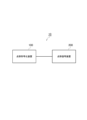
- FIG. 1 is a diagram illustrating an example of the configuration of a point cloud processing system 10 according to an embodiment.
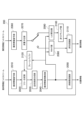
- FIG. 2 is a diagram illustrating an example of functional blocks of a point group decoding device 200 according to an embodiment.
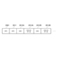
- FIG. 3 is a diagram showing an example of the configuration of encoded data (bit stream) received by the geometric information decoding unit 2010 of the point cloud decoding device 200 according to an embodiment.
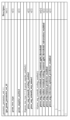
- FIG. 4 is a diagram showing an example of the syntax configuration of GPS2011.
- FIG. 5 is a flowchart showing an example of the operation of the tree synthesis unit 2020 of the point group decoding device 200 according to an embodiment.
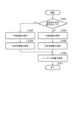
- FIG. 6 is a flowchart showing an example of the process of decoding the predictor information and the spherical coordinate residual in step S504.
- FIG. 1 is a diagram illustrating an example of the configuration of a point cloud processing system 10 according to an embodiment.
- FIG. 2 is a diagram illustrating an example of functional blocks of a point group decoding device 200 according to an
- FIG. 7 is a flowchart showing an example of the spherical coordinate residual decoding process in step S604.
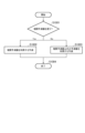
- FIG. 8 is a flowchart showing an example of the radius residual decoding process in step S702.
- FIG. 9 is a flowchart showing an example of the process of predicting position information in step S505.
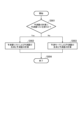
- FIG. 10 is a flowchart showing an example of the process of generating a predictor and calculating a predicted value using the predictor list in step S902.
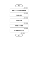
- FIG. 11 is a flowchart showing an example of the prediction process including the correlation predictor in step S1002.
- FIG. 12 is a flowchart showing an example of the process of decoding the predictor information and the spherical coordinate residual in step S504.
- FIG. 13 is a flowchart showing an example of the prediction of the position information in step S505.
- FIG. 14 is a flowchart showing an example of the process of generating a predictor according to the optimal predictor of the reference node and calculating a predicted value in step S1304.
- FIG. 15 is a diagram showing an example of functional blocks of the point group encoding device 100 according to this embodiment.
- FIG. 1 is a diagram showing a point cloud processing system 10 according to the present embodiment.
- the point cloud processing system 10 includes a point cloud encoding device 100 and a point cloud decoding device 200.
- the point cloud encoding device 100 is configured to generate encoded data (bit stream) by encoding an input point cloud signal.
- the point cloud decoding device 200 is configured to generate an output point cloud signal by decoding the bit stream.
- the input point cloud signal and the output point cloud signal are composed of position information and attribute information of each point in the point cloud.
- the attribute information is, for example, color information and reflectance of each point.
- Such a bit stream may be transmitted from the point group encoding device 100 to the point group decoding device 200 via a transmission path.
- the bit stream may be stored in a storage medium and then provided from the point group encoding device 100 to the point group decoding device 200.
- Point Cloud Decoding Device 200 Point Cloud Decoding Device 200
- the point group decoding device 200 according to this embodiment will be described with reference to Fig. 2.
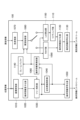
- Fig. 2 is a diagram showing an example of functional blocks of the point group decoding device 200 according to this embodiment.
- the point cloud decoding device 200 has a geometric information decoding unit 2010, a tree synthesis unit 2020, an approximate surface synthesis unit 2030, a geometric information reconstruction unit 2040, an inverse coordinate transformation unit 2050, an attribute information decoding unit 2060, an inverse quantization unit 2070, a RAHT unit 2080, an LoD calculation unit 2090, an inverse lifting unit 2100, an inverse color transformation unit 2110, and a frame buffer 2120.
- the geometric information decoding unit 2010 is configured to receive as input a bit stream related to geometric information (geometric information bit stream) from the bit streams output from the point cloud encoding device 100, and to decode the syntax.
- the decoding process is, for example, a context-adaptive binary arithmetic decoding process.
- the syntax includes control data (flags and parameters) for controlling the decoding process of the position information.
- the tree synthesis unit 2020 is configured to receive as input the control data decoded by the geometric information decoding unit 2010 and an occurrence code indicating at which node in the tree (described later) the point group exists, and generate tree information indicating in which area in the decoding target space the point exists.
- the decoding process of the occasion code may be configured to be performed within the tree synthesis unit 2020.
- This process divides the space to be decoded into rectangular parallelepipeds, refers to the occupancy code to determine whether a point exists in each rectangular parallelepiped, divides the rectangular parallelepiped that contains the point into multiple rectangular parallelepipeds, and then refers to the occupancy code.
- tree information can be generated.
- inter prediction when decoding such an occasion code, inter prediction, which will be described later, may be used.
- a method called "Octree” can be used, which recursively performs octree division on the above-mentioned rectangular parallelepiped, always treating it as a cube, and a method called “QtBt” can be used, which performs quadtree division and binary tree division in addition to octree division. Whether or not to use "QtBt" is transmitted as control data from the point cloud encoding device 100.
- the tree synthesis unit 2020 is configured to decode the coordinates of each point based on an arbitrary tree configuration determined by the point cloud encoding device 100.
- the approximate surface synthesis unit 2030 is configured to generate approximate surface information using the tree information generated by the tree synthesis unit 2020, and to decode the point cloud based on the approximate surface information.
- Approximate surface information is used to represent the area where the points are densely distributed on the object's surface, for example when decoding three-dimensional point cloud data of an object, by approximating the area where the points are present using a small plane, rather than decoding each point individually.
- the approximate surface synthesis unit 2030 can generate approximate surface information and decode the point cloud using a method called "Trisoup", for example.
- Trisoup a method called "Trisoup"
- a specific processing example of "Trisoup” will be described later.
- this processing can be omitted.
- the geometric information reconstruction unit 2040 is configured to reconstruct the geometric information (position information in the coordinate system assumed by the decoding process) of each point of the point cloud data to be decoded, based on the tree information generated by the tree synthesis unit 2020 and the approximate surface information generated by the approximate surface synthesis unit 2030.
- the inverse coordinate transformation unit 2050 is configured to receive the geometric information reconstructed by the geometric information reconstruction unit 2040 as input, transform it from the coordinate system assumed by the decoding process to the coordinate system of the output point cloud signal, and output position information.
- the frame buffer 2120 is configured to receive the geometric information reconstructed by the geometric information reconstruction unit 2040 as an input and store it as a reference frame.
- the stored reference frame is read from the frame buffer 2130 and used as a reference frame when the tree synthesis unit 2020 performs inter-prediction of temporally different frames.
- the time at which the reference frame is to be used for each frame may be determined based on, for example, control data transmitted as a bit stream from the point cloud encoding device 100.
- the attribute information decoding unit 2060 is configured to receive as input a bit stream related to attribute information (attribute information bit stream) from the bit streams output from the point cloud encoding device 100, and to decode the syntax.
- the decoding process is, for example, a context-adaptive binary arithmetic decoding process.
- the syntax includes control data (flags and parameters) for controlling the decoding process of the attribute information.
- the attribute information decoding unit 2060 is also configured to decode the quantized residual information from the decoded syntax.
- the inverse quantization unit 2070 is configured to perform an inverse quantization process based on the quantized residual information decoded by the attribute information decoding unit 2060 and the quantization parameter, which is one of the control data decoded by the attribute information decoding unit 2060, to generate inverse quantized residual information.
- the dequantized residual information is output to either the RAHT unit 2080 or the LoD calculation unit 2090 depending on the characteristics of the point group to be decoded.
- the control data decoded by the attribute information decoding unit 2060 specifies which unit the information is output to.
- the RAHT unit 2080 is configured to receive the inverse quantized residual information generated by the inverse quantization unit 2070 and the geometric information generated by the geometric information reconstruction unit 2040 as input, and to decode the attribute information of each point using a type of Haar transform (inverse Haar transform in the decoding process) called RAHT (Region Adaptive Hierarchical Transform).
- RAHT Region Adaptive Hierarchical Transform
- the LoD calculation unit 2090 is configured to receive the geometric information generated by the geometric information reconstruction unit 2040 and generate the LoD (Level of Detail).
- LoD is information for defining the reference relationship (the referencing point and the referenced point) to realize predictive coding, such as predicting attribute information of a certain point from attribute information of another point and encoding or decoding the prediction residual.
- LoD is information that defines a hierarchical structure in which each point contained in the geometric information is classified into multiple levels, and the attributes of points belonging to lower levels are encoded or decoded using attribute information of points belonging to higher levels.
- the inverse lifting unit 2100 is configured to decode attribute information of each point based on the hierarchical structure defined by the LoD, using the LoD generated by the LoD calculation unit 2090 and the inverse quantized residual information generated by the inverse quantization unit 2070.
- the method described in the above-mentioned non-patent document 1 can be used.
- the inverse color conversion unit 2110 is configured to perform inverse color conversion processing on the attribute information output from the RAHT unit 2080 or the inverse lifting unit 2100 when the attribute information to be decoded is color information and color conversion has been performed on the point cloud encoding device 100 side. Whether or not such inverse color conversion processing is performed is determined by the control data decoded by the attribute information decoding unit 2060.
- the point cloud decoding device 200 is configured to decode and output attribute information of each point in the point cloud through the above processing.
- geometric information decoding unit 2010 The control data decoded by the geometric information decoding unit 2010 will be described below with reference to FIGS.
- FIG. 3 shows an example of the structure of the encoded data (bit stream) received by the geometric information decoding unit 2010.
- the bit stream may include a GPS2011.
- a GPS2011 is also called a geometry parameter set, and is a collection of control data related to decoding of geometric information. A specific example will be described later.
- Each GPS2011 includes at least GPS id information for identifying each GPS2011 when multiple GPS2011 exist.
- the bit stream may include GSH2012A/2012B.
- GSH2012A/2012B is also called a geometry slice header or geometry data unit header, and is a collection of control data corresponding to a slice, which will be described later.
- slice will be used, but slice can also be read as data unit. Specific examples will be described later.
- GSH2012A/2012B includes at least GPS id information for specifying the GPS2011 corresponding to each GSH2012A/2012B.
- the bitstream may include slice data 2013A/2013B following GSH 2012A/2012B.
- Slice data 2013A/2013B includes data that encodes geometric information.
- bit stream is structured so that each slice data 2013A/2013B corresponds to one GSH 2012A/2012B and one GPS 2011.
- the GPS ID information is used to specify which GPS 2011 to refer to in GSH 2012A/2012B, so a common GPS 2011 can be used for multiple slice data 2013A/2013B.
- GPS2011 does not necessarily have to be transmitted for each slice.
- the bit stream can be configured so that GPS2011 is not encoded immediately before GSH2012B and slice data 2013B.
- FIG. 3 is merely an example. As long as GSH 2012A/2012B and GPS 2011 correspond to each slice data 2013A/2013B, elements other than those described above may be added as components of the bit stream.
- the bitstream may include a sequence parameter set (SPS) 2001.
- SPS sequence parameter set
- the bitstream when transmitted, may be shaped into a configuration different from that shown in FIG. 3.
- the bitstream may be combined with a bitstream decoded by an attribute information decoding unit 2060 (described later) and transmitted as a single bitstream.
- Figure 4 shows an example of the syntax configuration of GPS2011.
- syntax names explained below are merely examples. If the syntax functions explained below are similar, the syntax names may be different.
- GPS2011 may include GPS ID information (gsps_geom_parameter_set_id) for identifying each GPS2011.
- Descriptor column in Figure 4 indicates how each syntax is coded.
- ue(v) means that it is an unsigned zeroth-order exponential Golomb code, and u(1) means that it is a 1-bit flag.
- GPS2011 may include a flag (geom_tree_type) for controlling the tree type in the tree synthesis unit 2020.
- geom_tree_type For example, if the value of geom_tree_type is "1", it may be defined that predictive geometry coding is used, and if the value of geom_tree_type is "0", it may be defined that Octree is used.
- GPS2011 may include a flag (geom_angular_enabled) for controlling whether processing is performed in angular mode in the tree synthesis unit 2020.
- geom_angular_enabled when the value of geom_angular_enabled is "1", it may be defined that predictive geometry coding processing is performed in angular mode, and when the value of geom_angular_enabled is "0", it may be defined that predictive geometry coding processing is not performed in angular mode.
- GPS2011 may include a flag (ptree_ang_azimuth_scaling_enabled) in the tree synthesis unit 2020 for controlling whether the adaptive azimuth quantization mode is in angular mode.
- the adaptive azimuth quantization mode is a mode that performs adaptive quantization of the azimuth angle according to the radius.
- ptree_ang_azimuth_scaling_enabled For example, if the value of ptree_ang_azimuth_scaling_enabled is "1", it is defined that adaptive quantization of the azimuth angle according to the radius is performed, and if the value of ptree_ang_azimuth_scaling_enabled is "0", it is defined that adaptive quantization of the azimuth angle according to the radius is not performed.
- the predictor may also be used as a flag to control whether or not to use a predictor list when calculating (selecting) a predictor in angular mode.
- the predictor is considered to be a concept that includes a linear predictor.
- ptree_azimuth_scaling_enabled For example, if the value of ptree_azimuth_scaling_enabled is "1", it may be defined that the predictor list is used in the calculation of the predictor, and if the value of ptree_ang_azimuth_scaling_enabled is "0", it may be defined that the predictor list is not used in the calculation of the predictor.
- GPS2011 may include a value (ptree_ang_azimuth_step_minus1) related to the laser rotation speed for use in calculating the predicted azimuth angle in the tree synthesis unit 2020 in angular mode.
- ptree_ang_azimuth_step_minus1 a value related to the laser rotation speed for use in calculating the predicted azimuth angle in the tree synthesis unit 2020 in angular mode.
- GPS2011 may include, in the tree synthesis unit 2020, a threshold (ptree_ang_radius_residual_cording_context_qphi_threshold) for the number of azimuth steps used when decoding the radius residual in angular mode and adaptive azimuth quantization mode.
- a threshold ptree_ang_radius_residual_cording_context_qphi_threshold
- GPS2011 may include, in the tree synthesis unit 2020, a second threshold (ptree_ang_radius_residual_cording_context_qphi_threshold2) for the number of azimuth steps used when decoding the radius residual in the angular mode and adaptive azimuth quantization mode.
- a second threshold ptree_ang_radius_residual_cording_context_qphi_threshold2
- GPS2011 may include a flag (ptree_ang_radius_residual_cording_context_qphi_threshold_calculation_enabled) in the tree synthesis unit 2020 to control whether or not the decoder derives a threshold for the number of azimuth angle steps in the angular mode and adaptive azimuth angle quantization mode.
- a flag ptree_ang_radius_residual_cording_context_qphi_threshold_calculation_enabled
- ptree_ang_radius_residual_cording_context_qphi_threshold_calculation_enabled For example, if the value of ptree_ang_radius_residual_cording_context_qphi_threshold_calculation_enabled is "1", it may be defined that such a threshold is derived by the decoder, and if the value of ptree_ang_radius_residual_cording_context_qphi_threshold_calculation_enabled is "0", it may be defined that such a threshold is not derived by the decoder.
- GPS2011 may include a flag (ptree_ang_relation_predictor_enabled_flag) for controlling whether or not to use a correlation predictor using the correlation of multiple decoded nodes such as parent nodes in the tree synthesis unit 2020 in the angular mode and adaptive azimuth angle quantization mode.
- ptree_ang_relation_predictor_enabled_flag a flag for controlling whether or not to use a correlation predictor using the correlation of multiple decoded nodes such as parent nodes in the tree synthesis unit 2020 in the angular mode and adaptive azimuth angle quantization mode.
- ptree_ang_predictor_enabled_flag when the value of ptree_ang_predictor_enabled_flag is "1", it may be defined that such a correlation predictor is used, and when the value of ptree_ang_predictor_enabled_flag is "0", it may be defined that such a correlation predictor is not used.
- GPS2011 may include a flag (ptree_ang_reference_optimal_predictor_enabled_flag) for controlling whether to generate a predictor and perform prediction using the optimal predictor of the reference node in the tree synthesis unit 2020 in the angular mode and adaptive azimuth angle quantization mode.
- ptree_ang_reference_optimal_predictor_enabled_flag a flag for controlling whether to generate a predictor and perform prediction using the optimal predictor of the reference node in the tree synthesis unit 2020 in the angular mode and adaptive azimuth angle quantization mode.
- ptree_ang_predictor_enabled_flag if the value of ptree_ang_predictor_enabled_flag is "1", it may be defined that a predictor is generated using the optimal predictor of the reference node, and if the value of ptree_ang_reference_optimal_predictor_enabled_flag is "0", it may be defined that a predictor is not generated using the optimal predictor of the reference node.
- Tree synthesis unit 2020 An example of the operation of the tree synthesis unit 2020 will be described below with reference to FIGS.
- FIG. 5 is a flowchart showing an example of processing in the tree synthesis unit 2020. Note that the following describes an example of synthesizing trees using "Predictive geometry coding.”
- Predictive geometry coding is also called predictive tree.
- Predictive geometry coding is a method of decoding the residual of the position information of the point cloud data and the predicted position information based on an arbitrary tree structure determined by the point cloud encoding device 100, and adding the two together to decode the position information of the point cloud data.
- step S501 the tree synthesis unit 2020 determines whether decoding of position information of all point cloud data contained in the slice has been completed.
- This process for example, transmits information indicating the number of point cloud data contained in the slice to the GSH, and by comparing this number of point cloud data with the number of data already processed, it can be determined whether processing of all points has been completed.
- step S513 If decoding of position information for all point cloud data is complete, this operation proceeds to step S513 and ends the process. If decoding of position information for all point cloud data is not complete, this operation proceeds to step S502.
- step S502 the tree synthesis unit 2020 sets the parent node of the node to be decoded (node to be processed) in the point cloud data.
- the tree synthesis unit 2020 decodes the number of child nodes of each node and stores node indices for each node equal to the number of child nodes.
- the tree synthesis unit 2020 may refer to the array of indexes of the node, obtain one index stored at the end of the array, and set the node of the obtained index as the parent node of the node to be decoded.
- step S503 the tree synthesis unit 2020 determines whether to perform processing in angular mode.
- the tree synthesis unit 2020 can refer to the value of the above-mentioned geom_angular_enabled to determine whether to perform processing in angular mode.
- step S504 If processing is to be performed in angular mode, the operation proceeds to step S504; if processing is not to be performed in angular mode, the operation proceeds to step S510.
- step S504 the tree synthesis unit 2020 decodes the predictor information and the spherical coordinate residual.
- the spherical coordinate residual indicates the residual of the radius, azimuth angle, and laser ID.
- step S505 the tree synthesis unit 2020 predicts the position information based on the predictor information.
- the predictor information is a predictor index or a prediction mode.
- the tree synthesis unit 2020 first determines the type of predictor to use for prediction.
- the tree synthesis unit 2020 may determine whether to perform processing in adaptive azimuth angle quantization mode based on the value of ptree_ang_azimuth_scaling_enabled, and may determine the type of predictor to use based on the result of such determination.
- the tree synthesis unit 2020 may select the type of predictor to use from among multiple predictors calculated using a tree structure based on the decoded predictor mode.
- the tree synthesis unit 2020 may select a predictor to be used based on the decoded prediction mode from among multiple predictors calculated using a tree structure.
- the tree synthesis unit 2020 may store the position information of the decoded node as a predictor in a list, refer to the list for the predictor assigned to the decoded predictor index, and select the predictor type to be used.
- the tree synthesis unit 2020 uses that predictor as the predicted value of the position information. A specific example of the process will be described later.
- step S506 the tree synthesis unit 2020 reconstructs the spherical coordinates.
- the tree synthesis unit 2020 reconstructs the spherical coordinates by adding the decoded spherical coordinate residual and the predictor.
- step S507 the tree synthesis unit 2020 reconstructs the orthogonal integer coordinates.
- the tree synthesis unit 2020 can convert the spherical coordinates to orthogonal integer coordinates based on the reconstructed spherical coordinates.
- a specific method for this can be achieved, for example, by the method described in Non-Patent Document 1.
- step S5 After the reconstruction of the orthogonal integer coordinates is complete, the operation proceeds to step S508.
- step S508 the tree synthesis unit 2020 decodes the orthogonal integer coordinate residual.
- step S509 the tree synthesis unit 2020 reconstructs the original coordinates.
- the tree synthesis unit 2020 reconstructs the original coordinates by adding the decoded orthogonal integer coordinate residual and the reconstructed orthogonal integer coordinates.
- step S510 the tree synthesis unit 2020 predicts the location information. Specifically, the tree synthesis unit 2020 selects a predictor and sets the predictor as the predicted value of the location information.
- the tree synthesis unit 2020 may select a predictor based on the decoded predictor mode from among multiple predictors calculated based on a tree structure.
- step S511 the tree synthesis unit 2020 decodes the orthogonal integer coordinate residual.
- step S512 After decoding of the orthogonal integer coordinate residual is complete, the operation proceeds to step S512.
- step S512 the tree synthesis unit 2020 reconstructs the original coordinates.
- the tree synthesis unit 2020 reconstructs the original coordinates by adding the residual of the orthogonal integer coordinates decoded in step S511 to the position information predicted in step S510.
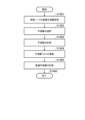
- FIG. 6 is a flowchart showing an example of the process of decoding predictor information and spherical coordinate residuals in step S504.
- step S601 the tree synthesis unit 2020 determines whether or not the adaptive azimuth angle quantization mode is selected based on the value of ptree_ang_azimuth_scaling_enabled.
- step S602. If the mode is adaptive azimuth angle quantization, the operation proceeds to step S603.
- step S602 the tree synthesis unit 2020 decodes the predictor index. After the decoding of the predictor index is completed, the operation proceeds to step S604.
- step S603 the tree synthesis unit 2020 decodes the prediction mode. After the prediction mode has been decoded, the operation proceeds to step S604.
- step S604 the tree synthesis unit 2020 decodes the number of azimuth angle steps. After the decoding of the number of azimuth angle steps is completed, the operation proceeds to step S605.
- step S605 the tree synthesis unit 2020 decodes the spherical coordinate residual. After the decoding is complete, the operation proceeds to step S606, where the processing ends.
- FIG. 7 is a flowchart showing an example of the spherical coordinate residual decoding process in step S604.
- step S701 the tree synthesis unit 2020 determines whether or not the adaptive azimuth angle quantization mode is selected based on the value of ptree_ang_azimuth_scaling_enabled.
- step S702 If the mode is adaptive azimuth angle quantization, the operation proceeds to step S702. On the other hand, if the mode is not adaptive azimuth angle quantization, the operation proceeds to step S704.
- step S702 the tree synthesis unit 2020 decodes the radius residual. After the radius residual decoding is completed, the operation proceeds to step S703.
- step S703 the tree synthesis unit 2020 decodes the azimuth angle residual. After the decoding of the azimuth angle residual is completed, the operation proceeds to step S706.
- step S704 the tree synthesis unit 2020 decodes the radius residual. After the radius residual decoding is completed, the operation proceeds to step S705.
- step S705 the tree synthesis unit 2020 decodes the azimuth angle residual. After the decoding of the azimuth angle residual is completed, the operation proceeds to step S706.
- step S706 the tree synthesis unit 2020 decodes the laser ID residual. After the decoding of the laser ID residual is complete, the operation proceeds to step S707 and ends the process.
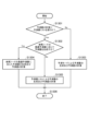
- FIG. 8 is a flowchart showing an example of the radius residual decoding process in step S702.
- step S801 the tree synthesis unit 2020 determines the context.
- the tree synthesis unit 2020 may use the decoded predictor index and the decoded azimuth angle step count to select one context index that meets a condition from among the four context indexes ctxIdx using one threshold value related to the azimuth angle step count as follows, and determine the context based on the selected context index.
- predIdx denotes a predictor index
- qphi denotes the azimuth angle step number
- x denotes a threshold for the azimuth angle step number
- the tree synthesis unit 2020 may use a specific hard-coded value as the threshold value x.
- the tree synthesis unit 2020 may use a specific hard-coded value such as 0 as the threshold value x.
- the tree synthesis unit 2020 may use the value of ptree_ang_radius_residual_cording_context_qphi_threshold as the threshold x.
- the tree synthesis unit 2020 may refer to the value of ptree_ang_radius_residual_cording_context_qphi_threshold_calculation_enabled, and if it determines that the threshold value x should be derived by the decoder, it may derive the threshold value x using syntax held by GPS2011.
- the tree synthesis unit 2020 may derive the threshold value x based on the value of ptree_ang_azimuth_step_minus1, which is a value related to the rotational speed of the laser to be used to calculate the predicted value of the azimuth angle.
- the tree synthesis unit 2020 may calculate the threshold value x as follows:
- A is a constant, and may be, for example, a power of 2.
- round(*) is a function that rounds off an argument and returns an integer value.
- the tree synthesis unit 2020 may use two thresholds for the number of azimuth angle steps and select a context index based on the conditions shown below.
- y denotes a second threshold value for the number of azimuth angle steps.
- the tree synthesis unit 2020 may use a specific value, such as 0, as the threshold y.
- the tree synthesis unit 2020 may use the value of ptree_ang_radius_residual_cording_context_qphi_threshold2 as the threshold y.
- the tree synthesis unit 2020 may derive the threshold y using the syntax held by GPS2011.
- the tree synthesis unit 2020 may make a judgment based on a threshold value for the number of azimuth angle steps and the number of decoded azimuth angle steps, and determine the context to be used for decoding the radial residual based on the judgment result. With such a configuration, the amount of code for the radial residual can be reduced.
- step S802 the tree synthesis unit 2020 decodes the radius residual.
- the tree synthesis unit 2020 performs context-adaptive binary arithmetic decoding processing based on the context determined in step S801.
- the tree synthesis unit 2020 may inverse quantize the decoded radius residual.
- the tree synthesis unit 2020 may perform inverse quantization with a uniform value for all nodes to be decoded, or may perform inverse quantization with a non-uniform value.
- the tree synthesis unit 2020 may perform inverse quantization with non-uniform values for all nodes to be decoded depending on the magnitude of the decoded radius residual.
- the tree synthesis unit 2020 may inverse quantize all nodes to be decoded using a value that changes linearly according to the magnitude of the radius residual, or may inverse quantize using an exponential function.
- the tree synthesis unit 2020 may be configured to inversely quantize the radius residual. By configuring in this way, it is possible to reduce the amount of code for the radius residual.
- FIG. 9 is a flowchart showing an example of the location information prediction process in step S505.
- step S901 the tree synthesis unit 2020 determines whether to use a predictor list to calculate a predictor.
- the tree synthesis unit 2020 may determine whether or not the adaptive azimuth angle quantization mode is selected based on the value of ptree_ang_azimuth_scaling_enabled, and determine the type of predictor to use in predictor calculation.
- step S902 If the predictor list is used, the operation proceeds to step S902; if the predictor list is not used, the operation proceeds to step S903.
- step S902 the tree synthesis unit 2020 calculates a predictor using the predictor list and predicts the position information.
- the tree synthesis unit 2020 may obtain from the list the position information of the decoded nodes stored as a predictor list that corresponds to the decoded predictor index.
- the tree synthesis unit 2020 may use the position information of the parent node as a predictor based on the decoded predictor index.
- the tree synthesis unit 2020 uses the predictor to calculate a predicted value of the position information.
- a specific example of the process for calculating the predicted value will be described later.
- step S904 ends the process.
- step S903 the tree synthesis unit 2020 selects a predictor to be used based on the decoded predictor mode from among multiple predictors calculated using the tree structure, and sets that predictor as the predicted value of the position information.
- the tree synthesis unit 2020 may select a mode to be used based on the decoded predictor mode from among a no prediction mode, a prediction mode based only on the parent node, a prediction mode based on the parent node and its parent node, and a prediction mode based on the parent node's parent node and its parent node.
- the tree synthesis unit 2020 can be realized by the method described in Non-Patent Document 1.
- step S904 ends the process.
- FIG. 10 is a flowchart showing an example of the process of generating a predictor using the predictor list and calculating a predicted value in step S902.
- step S1001 the tree synthesis unit 2020 determines whether to use a correlation predictor.
- a correlation predictor is a predictor that is generated using the correlation of decoded nodes such as parent nodes.
- the tree synthesis unit 2020 can refer to ptree_ang_relation_predictor_enabled_flag to determine whether to use a correlation predictor.
- step S1002 If a correlation predictor is used, the operation proceeds to step S1002; if a correlation predictor is not used, the operation proceeds to step S1003.
- step S1002 the tree synthesis unit 2020 performs prediction using a correlation predictor.
- the tree synthesis unit 2020 generates a correlation predictor or a predictor other than a correlation predictor based on the decoded predictor index, and predicts the position information of the node to be decoded. The details will be described later.
- step S1004 ends the process.
- step S1003 the tree synthesis unit 2020 performs prediction using a predictor other than the correlation predictor.
- the tree synthesis unit 2020 generates a predictor other than the correlation predictor based on the decoded predictor index, and predicts the position information of the node to be decoded.
- step S1004 ends the process.
- FIG. 11 is a flowchart showing an example of a prediction process including a correlation predictor in step S1002.
- step S1101 the tree synthesis unit 2020 obtains the first optimal predictor for the reference node.
- the reference node is a node that has already been decoded and is used to determine the predictor to be used by the node to be decoded.
- the tree synthesis unit 2020 decodes the position information in the reference node, and then calculates the radial residual when the parent node is used as the predictor and when the correlation predictor is used as the predictor.
- the first optimal predictor is the predictor used when the predictor index of the node to be decoded is 0, as described below, and is the predictor that produces the smaller radius residual among the calculated radius residuals.
- the tree synthesis unit 2020 calculates which of the parent node and the correlation predictor will result in a smaller radial residual, and selects the predictor that results in the smaller radial residual as the first optimal predictor.
- the tree synthesis unit 2020 uses the first optimal predictor of the reference node to determine whether to use the parent node or the correlation predictor as the predictor.
- predictor index 0 of the node to be decoded becomes the parent node
- predictor index 0 of the node to be decoded becomes the correlation predictor
- the tree synthesis unit 2020 may, for example, select as the reference node the node with the smallest azimuth among the nodes with an azimuth angle equal to or greater than the azimuth angle of the node decoded immediately before the node to be decoded, from among the laser IDs processed immediately before the laser ID of the node to be decoded.
- the tree synthesis unit 2020 may use the node decoded immediately before the node to be decoded as the reference node.
- the tree synthesis unit 2020 may use the node decoded immediately before the node to be decoded as the reference node.
- the tree synthesis unit 2020 obtains the first optimal predictor for the reference node.
- step S1102 the tree synthesis unit 2020 selects a predictor.
- the tree synthesis unit 2020 selects a predictor corresponding to the first optimal predictor of the acquired reference node.
- the tree synthesis unit 2020 sets the parent node as the predictor, and if the first optimal predictor of the reference node is a correlation predictor, the tree synthesis unit 2020 sets the correlation predictor as the predictor.
- the correlation predictor may be a linear predictor that is generated based on the correlation of a parent node and a parent node's parent node.
- r indicates the radius and ⁇ indicates the azimuth angle.
- the tree synthesis unit 2020 retrieves from the list the position information of the decoded nodes stored as a predictor list that corresponds to the decoded predictor index.
- step S1103 the tree synthesis unit 2020 calculates a prediction value. Specifically, the tree synthesis unit 2020 obtains a predictor corresponding to the decoded predictor index from the predictor list, and calculates the prediction value based on the obtained predictor.
- the predictor already contains the azimuth and radius of the decoded node, and the tree synthesis unit 2020 can calculate the predictor based on this information plus the decoded laser ID of the parent node, for example, using the method described in Non-Patent Document 2.
- step S1104 the tree synthesis unit 2020 updates the predictor list.
- the predictor list stores the decoded radius and azimuth as predictors.
- the tree synthesis unit 2020 updates the predictor list by storing the radius and azimuth angle decoded this time at index 0 of the predictor list.
- the tree synthesis unit 2020 may store the linear predictor used for prediction at index 0.
- updates to the first index and beyond can be achieved using the method described in Non-Patent Document 2.
- step S1105 the tree synthesis unit 2020 calculates the first optimal predictor.
- the calculated first optimal predictor is referenced when the node to be decoded is selected as the reference node in the decoding of nodes subsequent to the node to be decoded.
- the tree synthesis unit 2020 calculates the radial residual for the node to be decoded when the parent node is used as the predictor and when the correlation predictor is used as the predictor, calculates which predictor would have resulted in a smaller radial residual if it had been selected originally, and sets the predictor resulting in the smaller radial residual as the first optimal predictor.
- the tree synthesis unit 2020 compares the difference between the radius decoded at the node to be decoded and the radius of the parent node with the difference between the radius decoded at the node to be decoded and the radius of the correlation predictor, and if the difference with the parent node is smaller, it sets the parent node as the first optimal predictor, and if the difference with the correlation predictor is smaller, it sets the correlation predictor as the first optimal predictor.
- step S1106 ends the process.
- the tree synthesis unit 2020 may be configured to select whether the predictor with predictor index 0 is to be a parent node or a correlation predictor. By configuring in this way, predictor index 0 can be assigned to a more optimal predictor, thereby improving coding efficiency.
- FIG. 12 is a flowchart showing an example of the process of decoding predictor information and spherical coordinate residuals in step S504.
- step S1201 the tree synthesis unit 2020 determines whether or not the mode is adaptive azimuth angle quantization mode based on the value of ptree_ang_azimuth_scaling_enabled.
- step S1202. If the mode is adaptive azimuth angle quantization, the operation proceeds to step S1202. On the other hand, if the mode is not adaptive azimuth angle quantization, the operation proceeds to step S1203.
- step S1202 the tree synthesis unit 2020 determines whether to generate a predictor using the optimal predictor of the reference node and perform prediction.
- the tree synthesis unit 2020 may determine whether to generate a predictor using the optimal predictor of the reference node and perform prediction based on the value of ptree_ang_reference_optimal_predictor_enabled_flag.
- step S1205 If a predictor is to be generated using the optimal predictor of the reference node, the operation proceeds to step S1205; if a predictor is not to be generated using the optimal predictor of the reference node, the operation proceeds to step S1204.
- step S1203 the tree synthesis unit 2020 decodes the prediction mode. After the prediction mode has been decoded, the operation proceeds to step S604.
- step S1204 the tree synthesis unit 2020 decodes the predictor index. After the decoding of the predictor index is completed, the operation proceeds to step S1205.
- step S1205 the tree synthesis unit 2020 decodes the number of azimuth angle steps. After the decoding of the number of azimuth angle steps is completed, the operation proceeds to step S1206.
- step S1206 the tree synthesis unit 2020 decodes the spherical coordinate residual.
- the tree synthesis unit 2020 determines not to generate a predictor using the optimal predictor of the reference node based on the value of ptree_ang_reference_optimal_predictor_enabled_flag, then when decoding the radius residual, the context is selected based only on the number of azimuth angle steps.
- step S1207 ends the process.
- FIG. 13 is a flowchart showing an example of the location information prediction in step S505.
- step S1301 the tree synthesis unit 2020 determines whether to use a predictor list to calculate a predictor.
- the tree synthesis unit 2020 may determine whether or not the adaptive azimuth angle quantization mode is selected based on the value of ptree_ang_azimuth_scaling_enabled, and determine the type of predictor to use in predictor calculation.
- step S1202 If the predictor list is used, the operation proceeds to step S1202; if the predictor list is not used, the operation proceeds to step S1303.
- step S1302 the tree synthesis unit 2020 determines whether to generate a predictor using the optimal predictor of the reference node and perform prediction.
- the tree synthesis unit 2020 may determine whether to generate a predictor using the optimal predictor of the reference node and perform prediction based on the value of ptree_ang_reference_optimal_predictor_enabled_flag.
- step S1304 If a predictor is to be generated using the optimal predictor of the reference node, the operation proceeds to step S1304; if a predictor is not to be generated using the optimal predictor of the reference node, the operation proceeds to step S1305.
- step S1303 the tree synthesis unit 2020 selects a predictor to be used based on the decoded predictor mode from among multiple predictors calculated using the tree structure, and sets that predictor as the predicted value of the position information.
- the tree synthesis unit 2020 may select the mode to be used based on the decoded predictor mode from among a no prediction mode, a prediction mode based only on the parent node, a prediction mode based on the parent node and its parent node, and a prediction mode based on the parent node's parent node and its parent node.
- a selection can be realized, for example, by the method described in Non-Patent Document 1.
- step S1306 ends the process.
- step S1304 the tree synthesis unit 2020 generates a predictor according to the optimal predictor of the reference node and calculates the predicted value.
- the reference node is a node that has already been decoded and is used to determine the predictor that the node to be decoded will use.
- the optimal predictor is the predictor that, after decoding the position information at the reference node, calculates which predictor in the predictor list will produce the smallest radial residual, and as a result, produces the smallest radial residual.
- the tree synthesis unit 2020 obtains the optimal predictor for the reference node and calculates a prediction value based on this optimal predictor. Details will be described later.
- step S1306 ends the process.
- step S1305 the tree synthesis unit 2020 calculates a predictor using the predictor list and predicts the position information.
- the tree synthesis unit 2020 may obtain from the list the position information of the decoded nodes stored as a predictor list that corresponds to the decoded predictor index.
- the tree synthesis unit 2020 may use the position information of the parent node as a predictor based on the decoded predictor index.
- the tree synthesis unit 2020 uses the predictor to calculate the predicted value of the position information.
- step S1306 ends the process.
- FIG. 14 is a flowchart showing an example of the process of generating a predictor according to the optimal predictor of the reference node and calculating a predicted value in step S1304.
- step S1401 the tree synthesis unit 2020 obtains the optimal predictor for the reference node.
- the tree synthesis unit 2020 may select as the reference node the node with the smallest azimuth angle among the nodes with azimuth angles equal to or greater than the azimuth angle of the node decoded immediately before the node to be decoded, from among the laser IDs processed immediately before the laser ID of the node to be decoded.
- the tree synthesis unit 2020 may use the node decoded immediately before the node to be decoded as the reference node.
- the tree synthesis unit 2020 may use the node decoded immediately before the node to be decoded as the reference node.
- the tree synthesis unit 2020 obtains the optimal predictor for the reference node.
- step S1402 the tree synthesis unit 2020 selects a predictor.
- the tree synthesis unit 2020 selects a predictor according to the optimal predictor for the obtained reference node.
- the tree synthesis unit 2020 may use the optimal predictor of the reference node as the predictor as is, or may use a node of the same laser as the node to be decoded and of the same azimuth angle as the optimal predictor of the reference node as the predictor.
- step S1403 the tree synthesis unit 2020 calculates a predicted value.
- the obtained predictor includes information on the radius and azimuth angle of the decoded node.
- the tree synthesis unit 2020 can calculate the predictor based on the acquired predictor and the information including the decoded laser ID of the parent node, for example, using the method described in Non-Patent Document 2.
- step S1404 the tree synthesis unit 2020 updates the predictor list.
- the predictor list stores the decoded radius and azimuth as predictors.
- the tree synthesis unit 2020 may, for example, store the predictor used for decoding at the end of the predictor list.
- the tree synthesis unit 2020 may also separate the predictor list for each laser ID.
- the tree synthesis unit 2020 may create a new predictor list if the decoded laser ID has changed from the previous laser ID.
- the tree synthesis unit 2020 creates an independent predictor list for each laser ID, when selecting a predictor in step S1402, the tree synthesis unit 2020 refers to the predictor list corresponding to the laser ID of the reference node and selects a predictor.
- step S1405 the tree synthesis unit 2020 calculates the optimal predictor.
- the calculated optimal predictor is referenced when the node to be decoded is selected as the reference node in the decoding of nodes subsequent to the node to be decoded.
- the tree synthesis unit 2020 decodes the position information at the reference node, and then calculates which of the already decoded nodes will produce the smallest radial residual when used as a predictor, and determines the predictor that produces the smallest radial residual as the optimal predictor.
- step S1406 ends the process.
- the tree synthesis unit 2020 may be configured to calculate an optimal predictor in advance for a decoded node and make predictions by referring to the predictor. With this configuration, it is not necessary to decode the predictor index, and the coding efficiency can be improved.
- FIG. 15 is a diagram showing an example of functional blocks of the point cloud encoding device 100 according to this embodiment.
- the point cloud encoding device 100 has a coordinate transformation unit 1010, a geometric information quantization unit 1020, a tree analysis unit 1030, an approximate surface analysis unit 1040, a geometric information encoding unit 1050, a geometric information reconstruction unit 1060, a color conversion unit 1070, an attribute transfer unit 1080, a RAHT unit 1090, an LoD calculation unit 1100, a lifting unit 1110, an attribute information quantization unit 1120, an attribute information encoding unit 1130, and a frame buffer 1140.
- the coordinate conversion unit 1010 is configured to perform conversion processing from the three-dimensional coordinate system of the input point cloud to any different coordinate system.
- the coordinate conversion may, for example, convert the x, y, and z coordinates of the input point cloud into any s, t, and u coordinates by rotating the input point cloud.
- the coordinate system of the input point cloud may be used as is.
- the geometric information quantization unit 1020 is configured to quantize the position information of the input point group after coordinate transformation and remove points with overlapping coordinates.
- the quantization step size is 1, the position information of the input point group and the position information after quantization match. In other words, when the quantization step size is 1, it is equivalent to not performing quantization.
- the tree analysis unit 1030 is configured to use position information of the quantized point cloud as input, and to generate an occurrence code that indicates at which node in the encoding target space the point exists, based on the tree structure described below.
- the tree analysis unit 1030 is configured to generate a tree structure by recursively dividing the encoding target space into rectangular parallelepipeds.
- a tree structure can be generated by recursively dividing the rectangular parallelepiped into multiple rectangular parallelepipeds until the rectangular parallelepiped reaches a specified size.
- Each such rectangular parallelepiped is called a node.
- Each rectangular parallelepiped generated by dividing a node is called a child node, and the occurrence code is expressed as 0 or 1 to indicate whether or not a point is contained within a child node.
- the tree analysis unit 1030 is configured to generate an occupancy code while recursively dividing the node until it reaches a predetermined size.
- a method called "Octree” can be used that recursively divides the above-mentioned rectangular parallelepiped into octrees, always treating the rectangular parallelepiped as a cube, and a method called “QtBt” can be used that divides the rectangular parallelepiped into quadtrees and binary trees in addition to the octree division.
- the tree analysis unit 1030 determines the tree structure, and the determined tree structure is transmitted to the point cloud decoding device 200 as control data.
- the tree-structured control data may be configured so that it can be decoded using the procedures described in Figures 7 and 8.
- the approximate surface analysis unit 1040 is configured to generate approximate surface information using the tree information generated by the tree analysis unit 1030.
- Approximate surface information is used to represent the area where the points are densely distributed on the object's surface, for example when decoding three-dimensional point cloud data of an object, by approximating the area where the points are present using a small plane, rather than decoding each point individually.
- the approximate surface analysis unit 1040 may be configured to generate approximate surface information using, for example, a method called "Trisoup.” Furthermore, when decoding a sparse point cloud acquired by Lidar or the like, this process can be omitted.
- the geometric information encoding unit 1050 is configured to generate a bit stream (geometric information bit stream) by encoding syntax such as the occupancy code generated by the tree analysis unit 1030 and the approximate surface information generated by the approximate surface analysis unit 1040.
- the bit stream may include, for example, the syntax described in FIG. 4.
- the encoding process is, for example, a context-adaptive binary arithmetic encoding process.
- the syntax includes control data (flags and parameters) for controlling the decoding process of the position information.
- the geometric information reconstruction unit 1060 is configured to reconstruct the geometric information of each point of the point cloud data to be encoded (the coordinate system assumed by the encoding process, i.e., the position information after the coordinate transformation in the coordinate transformation unit 1010) based on the tree information generated by the tree analysis unit 1030 and the approximate surface information generated by the approximate surface analysis unit 1040.
- the frame buffer 1140 is configured to receive the geometric information reconstructed by the geometric information reconstruction unit 1060 and store it as a reference frame.
- the stored reference frame is read from the frame buffer 1140 and used as the reference frame when the tree analysis unit 1030 performs inter-prediction of temporally different frames.
- which reference frame to use for each frame may be determined based on, for example, the value of a cost function representing the encoding efficiency, and information on the reference frame to be used may be transmitted to the point cloud decoding device 200 as control data.
- the color conversion unit 1070 is configured to perform color conversion when the input attribute information is color information. It is not necessary to perform color conversion, and whether or not to perform color conversion processing is coded as part of the control data and transmitted to the point cloud decoding device 200.
- the attribute transfer unit 1080 is configured to correct the attribute values so as to minimize distortion of the attribute information, based on the position information of the input point cloud, the position information of the point cloud after reconstruction in the geometric information reconstruction unit 1060, and the attribute information after color change in the color conversion unit 1070.
- a specific correction method for example, the method described in Non-Patent Document 1 can be applied.
- the RAHT unit 1090 is configured to receive the attribute information transferred by the attribute transfer unit 1080 and the geometric information generated by the geometric information reconstruction unit 1060 as input, and to generate residual information for each point using a type of Haar transform called RAHT (Region Adaptive Hierarchical Transform).
- RAHT Regular Adaptive Hierarchical Transform
- the LoD calculation unit 1100 is configured to receive the geometric information generated by the geometric information reconstruction unit 1060 and generate the LoD (Level of Detail).
- LoD is information for defining the reference relationship (the referencing point and the referenced point) to realize predictive coding, such as predicting attribute information of a certain point from attribute information of another point and encoding or decoding the prediction residual.
- LoD is information that defines a hierarchical structure in which each point contained in the geometric information is classified into multiple levels, and the attributes of points belonging to lower levels are encoded or decoded using attribute information of points belonging to higher levels.
- the lifting unit 1110 is configured to generate residual information by a lifting process using the LoD generated by the LoD calculation unit 1100 and the attribute information after attribute transfer by the attribute transfer unit 1080.
- the method described in the above-mentioned non-patent document 1 may be used.
- the attribute information quantization unit 1120 is configured to quantize the residual information output from the RAHT unit 1090 or the lifting unit 1110.
- a quantization step size of 1 is equivalent to no quantization being performed.
- the attribute information encoding unit 1130 is configured to perform encoding processing using the quantized residual information output from the attribute information quantization unit 1120 as syntax, and generate a bit stream related to the attribute information (attribute information bit stream).
- the encoding process is, for example, a context-adaptive binary arithmetic encoding process.
- the syntax includes control data (flags and parameters) for controlling the decoding process of the attribute information.
- the point cloud encoding device 100 is configured to perform encoding processing using the position information and attribute information of each point in the point cloud as input, and to output a geometric information bit stream and an attribute information bit stream through the above processing.
- point cloud encoding device 100 and point cloud decoding device 200 may be realized as a program that causes a computer to execute each function (each process).
- the present invention has been described using the point cloud encoding device 100 and the point cloud decoding device 200 as examples, but the present invention is not limited to such examples and can be similarly applied to a point cloud encoding/decoding system having the functions of the point cloud encoding device 100 and the point cloud decoding device 200.
- Point cloud processing system 100 Point cloud encoding device 1010. Coordinate conversion unit 1020... Geometric information quantization unit 1030... Tree analysis unit 1040... Approximate surface analysis unit 1050... Geometric information encoding unit 1060... Geometric information reconstruction unit 1070... Color conversion unit 1080... Attribute transfer unit 1090... RAHT unit 1100... LoD calculation unit 1110... Lifting unit 1120... Attribute information quantization unit 1130...
- Attribute Information encoding unit 1140 For example, attribute Information encoding unit 1140...frame buffer 200...point cloud decoding device 2010...geometric information decoding unit 2020...tree synthesis unit 2030...approximate surface synthesis unit 2040...geometric information reconstruction unit 2050...inverse coordinate transformation unit 2060...attribute information decoding unit 2070...inverse quantization unit 2080...RAHT unit 2090...LoD calculation unit 2100...inverse lifting unit 2110...inverse color transformation unit 2120...frame buffer
Landscapes
- Engineering & Computer Science (AREA)
- Multimedia (AREA)
- Signal Processing (AREA)
- Physics & Mathematics (AREA)
- General Physics & Mathematics (AREA)
- Theoretical Computer Science (AREA)
- Compression, Expansion, Code Conversion, And Decoders (AREA)
- Compression Or Coding Systems Of Tv Signals (AREA)
Priority Applications (1)
| Application Number | Priority Date | Filing Date | Title |
|---|---|---|---|
| US19/351,098 US20260039849A1 (en) | 2023-04-14 | 2025-10-06 | Point cloud decoding device, point cloud decoding method, and program |
Applications Claiming Priority (2)
| Application Number | Priority Date | Filing Date | Title |
|---|---|---|---|
| JP2023-066201 | 2023-04-14 | ||
| JP2023066201A JP2024152166A (ja) | 2023-04-14 | 2023-04-14 | 点群復号装置、点群復号方法及びプログラム |
Related Child Applications (1)
| Application Number | Title | Priority Date | Filing Date |
|---|---|---|---|
| US19/351,098 Continuation US20260039849A1 (en) | 2023-04-14 | 2025-10-06 | Point cloud decoding device, point cloud decoding method, and program |
Publications (1)
| Publication Number | Publication Date |
|---|---|
| WO2024214442A1 true WO2024214442A1 (ja) | 2024-10-17 |
Family
ID=93059049
Family Applications (1)
| Application Number | Title | Priority Date | Filing Date |
|---|---|---|---|
| PCT/JP2024/008606 Ceased WO2024214442A1 (ja) | 2023-04-14 | 2024-03-06 | 点群復号装置、点群復号方法及びプログラム |
Country Status (3)
| Country | Link |
|---|---|
| US (1) | US20260039849A1 (enExample) |
| JP (1) | JP2024152166A (enExample) |
| WO (1) | WO2024214442A1 (enExample) |
Cited By (1)
| Publication number | Priority date | Publication date | Assignee | Title |
|---|---|---|---|---|
| US20240348832A1 (en) * | 2023-04-17 | 2024-10-17 | Qualcomm Incorporated | Predictive geometry coding for point cloud compression |
Citations (2)
| Publication number | Priority date | Publication date | Assignee | Title |
|---|---|---|---|---|
| US20220108484A1 (en) * | 2020-10-07 | 2022-04-07 | Qualcomm Incorporated | Predictive geometry coding in g-pcc |
| US20220207780A1 (en) * | 2020-12-29 | 2022-06-30 | Qualcomm Incorporated | Inter prediction coding for geometry point cloud compression |
-
2023
- 2023-04-14 JP JP2023066201A patent/JP2024152166A/ja active Pending
-
2024
- 2024-03-06 WO PCT/JP2024/008606 patent/WO2024214442A1/ja not_active Ceased
-
2025
- 2025-10-06 US US19/351,098 patent/US20260039849A1/en active Pending
Patent Citations (2)
| Publication number | Priority date | Publication date | Assignee | Title |
|---|---|---|---|---|
| US20220108484A1 (en) * | 2020-10-07 | 2022-04-07 | Qualcomm Incorporated | Predictive geometry coding in g-pcc |
| US20220207780A1 (en) * | 2020-12-29 | 2022-06-30 | Qualcomm Incorporated | Inter prediction coding for geometry point cloud compression |
Cited By (2)
| Publication number | Priority date | Publication date | Assignee | Title |
|---|---|---|---|---|
| US20240348832A1 (en) * | 2023-04-17 | 2024-10-17 | Qualcomm Incorporated | Predictive geometry coding for point cloud compression |
| US12425658B2 (en) * | 2023-04-17 | 2025-09-23 | Qualcomm Incorporated | Predictive geometry coding for point cloud compression |
Also Published As
| Publication number | Publication date |
|---|---|
| JP2024152166A (ja) | 2024-10-25 |
| US20260039849A1 (en) | 2026-02-05 |
Similar Documents
| Publication | Publication Date | Title |
|---|---|---|
| JP7651760B2 (ja) | 点群復号装置、点群復号方法及びプログラム | |
| WO2022070469A1 (ja) | 点群復号装置、点群復号方法及びプログラム | |
| JP7651762B2 (ja) | 点群復号装置、点群復号方法及びプログラム | |
| JP7499665B2 (ja) | 点群復号装置、点群復号方法及びプログラム | |
| JP7499666B2 (ja) | 点群復号装置、点群復号方法及びプログラム | |
| JP2023007934A (ja) | 点群復号装置、点群復号方法及びプログラム | |
| US20260039849A1 (en) | Point cloud decoding device, point cloud decoding method, and program | |
| JP7680398B2 (ja) | 点群復号装置、点群復号方法及びプログラム | |
| JP7829505B2 (ja) | 点群復号装置、点群復号方法及びプログラム | |
| JP7773961B2 (ja) | 点群復号装置、点群復号方法及びプログラム | |
| JP7851868B2 (ja) | 点群復号装置、点群復号方法及びプログラム | |
| JP7773959B2 (ja) | 点群復号装置、点群復号方法及びプログラム | |
| JP7812781B2 (ja) | 点群復号装置、点群復号方法及びプログラム | |
| JP7773960B2 (ja) | 点群復号装置、点群復号方法及びプログラム | |
| JP2024152417A (ja) | 点群復号装置、点群復号方法及びプログラム | |
| JP2024152169A (ja) | 点群復号装置、点群復号方法及びプログラム | |
| JP2024093896A (ja) | 点群復号装置、点群復号方法及びプログラム | |
| WO2024079985A1 (ja) | 点群復号装置、点群復号方法及びプログラム | |
| WO2024009561A1 (ja) | 点群復号装置、点群復号方法及びプログラム | |
| JP2025009525A (ja) | 点群復号装置、点群復号方法及びプログラム | |
| JP2025009524A (ja) | 点群復号装置、点群復号方法及びプログラム | |
| JP2025009504A (ja) | 点群復号装置、点群復号方法及びプログラム | |
| WO2025150285A1 (ja) | 点群復号装置、点群復号方法及びプログラム | |
| JP2025009505A (ja) | 点群復号装置、点群復号方法及びプログラム | |
| WO2025150284A1 (ja) | 点群復号装置、点群復号方法及びプログラム |
Legal Events
| Date | Code | Title | Description |
|---|---|---|---|
| 121 | Ep: the epo has been informed by wipo that ep was designated in this application |
Ref document number: 24788472 Country of ref document: EP Kind code of ref document: A1 |
|
| NENP | Non-entry into the national phase |
Ref country code: DE |
|
| 122 | Ep: pct application non-entry in european phase |
Ref document number: 24788472 Country of ref document: EP Kind code of ref document: A1 |