WO2024214215A1 - 測位装置、測位方法、及びプログラム - Google Patents
測位装置、測位方法、及びプログラム Download PDFInfo
- Publication number
- WO2024214215A1 WO2024214215A1 PCT/JP2023/014885 JP2023014885W WO2024214215A1 WO 2024214215 A1 WO2024214215 A1 WO 2024214215A1 JP 2023014885 W JP2023014885 W JP 2023014885W WO 2024214215 A1 WO2024214215 A1 WO 2024214215A1
- Authority
- WO
- WIPO (PCT)
- Prior art keywords
- positioning
- solution
- gnss
- positioning solution
- reliability determination
- Prior art date
- Legal status (The legal status is an assumption and is not a legal conclusion. Google has not performed a legal analysis and makes no representation as to the accuracy of the status listed.)
- Ceased
Links
Images




Classifications
-
- G—PHYSICS
- G01—MEASURING; TESTING
- G01S—RADIO DIRECTION-FINDING; RADIO NAVIGATION; DETERMINING DISTANCE OR VELOCITY BY USE OF RADIO WAVES; LOCATING OR PRESENCE-DETECTING BY USE OF THE REFLECTION OR RERADIATION OF RADIO WAVES; ANALOGOUS ARRANGEMENTS USING OTHER WAVES
- G01S19/00—Satellite radio beacon positioning systems; Determining position, velocity or attitude using signals transmitted by such systems
- G01S19/38—Determining a navigation solution using signals transmitted by a satellite radio beacon positioning system
- G01S19/39—Determining a navigation solution using signals transmitted by a satellite radio beacon positioning system the satellite radio beacon positioning system transmitting time-stamped messages, e.g. GPS [Global Positioning System], GLONASS [Global Orbiting Navigation Satellite System] or GALILEO
- G01S19/42—Determining position
- G01S19/43—Determining position using carrier phase measurements, e.g. kinematic positioning; using long or short baseline interferometry
-
- G—PHYSICS
- G01—MEASURING; TESTING
- G01S—RADIO DIRECTION-FINDING; RADIO NAVIGATION; DETERMINING DISTANCE OR VELOCITY BY USE OF RADIO WAVES; LOCATING OR PRESENCE-DETECTING BY USE OF THE REFLECTION OR RERADIATION OF RADIO WAVES; ANALOGOUS ARRANGEMENTS USING OTHER WAVES
- G01S19/00—Satellite radio beacon positioning systems; Determining position, velocity or attitude using signals transmitted by such systems
- G01S19/38—Determining a navigation solution using signals transmitted by a satellite radio beacon positioning system
- G01S19/39—Determining a navigation solution using signals transmitted by a satellite radio beacon positioning system the satellite radio beacon positioning system transmitting time-stamped messages, e.g. GPS [Global Positioning System], GLONASS [Global Orbiting Navigation Satellite System] or GALILEO
- G01S19/42—Determining position
- G01S19/48—Determining position by combining or switching between position solutions derived from the satellite radio beacon positioning system and position solutions derived from a further system
- G01S19/49—Determining position by combining or switching between position solutions derived from the satellite radio beacon positioning system and position solutions derived from a further system whereby the further system is an inertial position system, e.g. loosely-coupled
Definitions
- This disclosure relates to a method for measuring the position of a moving object with high accuracy in an outdoor environment.
- GNSS Global Navigation Satellite Systems
- GLONASS Global Navigation Satellite Systems
- Galileo Galileo
- BeiDou BeiDou
- QZSS QZSS
- NAVIC NAVIC
- multi-GNSS multi-constellation GNSS
- Increasing the number of satellites used for positioning improves the availability of satellite positioning in environments where it is difficult to receive GNSS satellite signals.
- a difficult reception environment is a reception environment where there are buildings and other structures that block the satellite signals around the satellite signal reception position.
- DOP Deution of Precision
- Another factor that can degrade positioning accuracy is the effect of multipath, where satellite signals are reflected and diffracted by structures before reaching the receiving position.
- multipath There are two types of multipath: multipath of visible satellite signals that involves direct waves, and multipath of invisible satellites or NLOS (Non Line-of-sight) satellites that does not involve direct waves. The latter has a greater impact on the degradation of positioning accuracy.
- GNSS positioning methods include a code positioning method that uses a satellite-specific code (pseudo-random bit sequence) included in the navigation message as a clue to measure the pseudo-range from the satellite position to the receiving position, and calculates four unknowns from the pseudo-ranges of four or more satellite signals: the three-dimensional coordinates of the receiving position and the clock bias of the GNSS receiver (time offset relative to the satellite system); and a carrier phase positioning method that uses the carrier phase information of the satellite signal in addition to the pseudo-range to perform precise positioning calculations.
- a satellite-specific code prseudo-random bit sequence
- the carrier phase positioning method improves positioning resolution by resolving the wave number ambiguity of the carrier wave from the satellite position to the receiving position after correcting systematic errors that are not dependent on the receiving environment, such as satellite orbit error, satellite clock bias, and propagation delays in the ionosphere and troposphere.
- the chip length of the navigation message of a GPS L1 signal (the distance obtained by multiplying the time equivalent to one chip by the speed of light) is about 300m, and approximately 1/100 of this, or about 3m, is the guideline for the limit of positioning accuracy.
- the wavelength of the carrier wave of the L1 signal is about 19cm, so the carrier phase positioning method can achieve positioning accuracy on the order of millimeters in an ideal receiving environment.
- a Float solution is output as an estimated solution when the wave number ambiguity cannot be resolved.
- Known carrier phase positioning methods include the RTK (Real time Kinematic)-GNSS positioning method, which uses observation data from a reference station whose position is known to correct systematic errors and calculate a baseline vector, and the PPP (Precise Point Positioning)-RTK method, which uses correction data generated individually for each element (correction data for satellite orbit, clock, or propagation delay).
- a hybrid positioning method that combines absolute positioning means using GNSS with relative positioning means using sensors has been devised as a way to improve positioning accuracy in poor reception environments.
- a hybrid positioning system that uses an IMU (Inertial Measurement Unit) that measures three-axis displacement and attitude angle using acceleration sensors and angular velocity (gyro) sensors as a relative positioning method is called an INS (Inertial Navigation System).
- the INS performs coupling processing of position data from GNSS positioning and discrete-time time series data from sensor data, and estimates the state (true position value) from observed values containing errors by performing state estimation using a filter based on a state space model (such as a Kalman filter), and outputs a hybrid positioning solution.
- a state space model such as a Kalman filter
- the distribution state of GNSS positioning solutions shows a variation (normal white noise) close to a Gaussian distribution centered on the true value.
- the distribution state of GNSS positioning solutions does not show normality where the error from the true value is centered at zero due to the bias of the positions of visible satellites in the sky, which depends on the relative positional relationship between the satellite position and the structure, and the effects of multipath.
- the distribution state of GNSS positioning solutions changes over time.
- the Kalman filter performs state estimation under the assumption that the observation value has a normal error, there are cases where the true value estimation of the position does not function effectively if the observation data contains outlier errors.
- One way to deal with this is to change the weighting of the GNSS positioning solutions used in the combined positioning calculation depending on the expected accuracy of the GNSS positioning solutions.
- the weighting of the GNSS positioning solutions used in the combined positioning calculation is often changed based on the error ellipse value calculated from the DOP value of the satellite used for positioning.
- the weighting of the GNSS positioning solutions used in the combined positioning calculation is often changed based on the type of GNSS positioning solution (FIX, Float, etc.).
- a float solution may have a large error in a poor reception environment, just like a code solution, but in an ideal reception environment, it may be close to the true value. Therefore, it is not possible to determine with sufficient reliability whether an RTK-GNSS solution is a valid solution based on the type of the fixed or float solution.
- GNSS positioning solutions containing errors are incorporated into the composite positioning calculation without effectively eliminating them, errors will occur in the composite positioning solution.
- a vehicle or other vehicle enters an area where GNSS satellite signals cannot be received, such as a tunnel or underground parking lot, and transitions to an autonomous navigation (dead reckoning) state using relative positioning means, i.e., a dead reckoning state, there is a problem that an offset error will continue to occur in the positioning solution.
- this disclosure aims to maintain the positioning accuracy of moving objects such as vehicles even in environments where it is difficult to receive GNSS satellite signals.
- the invention of claim 1 is a positioning device that performs positioning of a moving object, and has an absolute positioning unit that performs GNSS positioning calculations to obtain a GNSS positioning solution, a positioning solution reliability determination unit that calculates a positioning solution reliability determination index by performing a positioning solution reliability determination on whether the GNSS positioning solution is a valid solution close to the true value, and a composite positioning unit that outputs a composite positioning solution with relative positioning using the GNSS positioning solution based on the positioning solution reliability determination index, or outputs a dead reckoning positioning solution without using the GNSS positioning solution.
- the present invention has the effect of maintaining high positioning accuracy for a mobile object even in an environment where it is difficult to receive GNSS satellite signals.
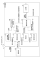
- FIG. 1 is a configuration diagram of a positioning device according to an embodiment
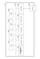
- FIG. 2 is a diagram illustrating an electrical hardware configuration of the positioning device according to the embodiment.
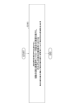
- FIG. 2 is a diagram illustrating an example of the configuration of an absolute positioning unit according to the embodiment.
- 13 is a flowchart showing the processing of the positioning device at a certain time epoch.
- 4 is a flowchart showing a process according to the first embodiment
- FIG. 11 is a diagram showing an example (part 1) of performing inspection using a plurality of antennas according to the first embodiment
- 10 is a flowchart showing a process according to a second embodiment;
- FIG. 13 is a diagram showing an example (part 2) of performing inspection using a plurality of antennas according to the second embodiment; 13 is a flowchart showing a process according to a third embodiment.
- FIG. 13 is a diagram showing an example of performing a test (time-axis redundancy calculation) by observing redundant positioning solutions over time according to the third embodiment; 13 is a flowchart showing a process according to a fourth embodiment;
- FIG. 13 is a diagram illustrating an example of testing the reliability based on the behavior (load tolerance) of the positioning solution for each positioning calculation condition according to the fourth embodiment.
- 13 is a flowchart showing a process according to the fifth embodiment.
- FIG. 13 is a diagram illustrating an example of performing verification using a redundant reference station according to the fifth embodiment.
- FIG. 13 is a diagram showing an example in which verification is performed using two or more redundant reference stations according to a modified example of the fifth embodiment.
- 1A is a diagram showing a state transition to a dead reckoning state by combined positioning of a conventional method
- FIG. 1B is a diagram showing a state transition to a dead reckoning state by combined positioning of the methods of each embodiment.
- Fig. 1 is a configuration diagram of the positioning device of the present embodiment.
- a vehicle such as an automobile will be described as an example of a moving body.
- the moving body includes not only a vehicle but also an air vehicle such as a drone.
- the positioning device (composite positioning device) 3 has a positioning calculation condition setting unit 21 and a communication unit 22.
- the positioning device 3 also has a GNSS antenna 30, an absolute positioning unit 31, a clock unit 32, a relative positioning unit 33, a positioning solution reliability determination unit 34, a composite positioning unit 35, and an output unit 36.
- the positioning calculation condition setting unit 21 outputs the calculation conditions when the absolute positioning unit 31 executes a positioning calculation using a navigation satellite to the absolute positioning unit 31 and the positioning solution reliability determination unit 34.
- the positioning calculation condition setting unit 21 may be equipped with a human interface for setting the calculation conditions and a storage device for storing the set calculation conditions.
- the communication unit 22 receives observation data (correction data) from the RTK-GNSS reference station and outputs it to the absolute positioning unit 31.
- the GNSS antenna 30 receives GNSS satellite signals and outputs them to the absolute positioning unit 31.
- the absolute positioning unit 31 uses a navigation satellite signal received by a navigation satellite signal antenna (hereinafter referred to as the "GNSS antenna") to perform positioning calculation processing to calculate the absolute position (latitude, longitude, altitude).
- the absolute positioning unit 31 is composed of a GNSS receiving device (GNSS receiver) and the like.
- the positioning method used by the absolute positioning unit 31 to perform GNSS positioning calculations may be either the code positioning method or the carrier phase positioning method, but it is assumed that the latter method will mainly be used.
- the absolute positioning unit 31 is also assumed to support multi-GNSS positioning, which performs positioning calculations using a mixture of satellites from multiple navigation satellite systems.
- the absolute positioning unit 31 outputs the GNSS positioning solution obtained from the result of the GNSS positioning calculation, and the observation data (Doppler frequency, pseudorange, carrier phase, etc.) obtained during the intermediate process of the positioning calculation to the positioning solution reliability determination unit 34.
- the absolute positioning unit 31 has a function that can simultaneously execute multiple positioning calculation processes, and executes positioning calculation processes under different conditions input from the positioning calculation condition setting unit 21.
- FIG. 3 is an overall configuration diagram of a communication system in such an embodiment.
- the communication system 1 is constructed by a GNSS receiver 31A as the absolute positioning unit 31, and a server 5.
- the server 5 has a positioning engine 50.
- the GNSS receiver 31A and the server 5 can communicate data via a communication network 100 such as a mobile phone network or the Internet.
- the RF signal processing unit 31a including the RF front-end processing circuit of the GNSS receiver 31A and the baseband signal processing unit 31b are arranged inside a terminal installed in a vehicle or the like to be positioned, and the observation data output here is transferred to a server 5 (cloud processing platform) connected over a network via a communication IF 31c for mobile communication or the like, and the positioning calculation process is executed on the server 5.
- the positioning calculation result is transmitted to the GNSS receiver 31A and transferred to each functional unit of the positioning device 3.
- the positioning calculation condition setting unit 21 or the positioning solution reliability determination unit 34 may be located on the server 5 side.
- the clock unit 32 acquires from the absolute positioning unit 31 a time synchronization signal that is time-synchronized with the GNSS satellite signal received by the absolute positioning unit 31, and supplies highly accurate time information synchronized with UTC (Coordinated Universal Time) to each functional unit.
- the clock unit 32 is equipped with a high-precision oscillator such as an OCXO (Oven Controlled Crystal Oscillator), and even if the GNSS satellite signal is temporarily interrupted, it maintains highly accurate time through holdover operation and continues to supply time information to each unit.
- the relative positioning unit 33 is, for example, configured with an IMU (Inertial Measurement Unit) that uses an acceleration sensor and an angular velocity (gyro) sensor to measure three-axis displacement and attitude angle.
- IMU Inertial Measurement Unit
- gyro angular velocity
- the gyro sensor used may be a MEMS (Micro Electro Mechanical Systems) or an iFOG (interferometric Fiber Optical Gyroscope), depending on the accuracy requirements of the application.
- the relative positioning unit 33 outputs the amount of relative displacement calculated from the observation data (detection data) of each sensor (acceleration sensor and angular velocity sensor) and the observation data of each sensor to the composite positioning unit 35.
- the relative positioning unit 33 may be equipped with VIO (Visual Inertial Odometry) using a camera and LIO (Lidar Inertial Odometry) using LiDAR.
- VIO Visual Inertial Odometry
- LIO Lidar Inertial Odometry
- the data output from the relative positioning unit 33 may be used in deriving a positioning solution reliability judgment index in the positioning solution reliability judgment unit 34.
- the positioning solution reliability determination unit 34 determines whether the GNSS positioning solution calculated by the absolute positioning unit 31 is a valid solution close to the true value from the data input from the absolute positioning unit 31, and outputs the determination result to the composite positioning unit as a GNSS positioning solution reliability determination index (information indicating whether it is usable or not).
- GNSS positioning solution reliability determination index is also referred to as the "positioning solution reliability determination index”.
- the composite positioning unit 35 uses the absolute positioning solution and observation data by GNSS positioning output from the absolute positioning unit 31 and input via the positioning solution reliability judgment unit 34, and the relative positioning measurement results by each sensor and the observation data of each sensor input from the relative positioning unit 33, and outputs a composite positioning solution (or a "positioning solution” if no compounding is performed) by a composite positioning calculation using a Bayes filter such as a Kalman filter, an extended Kalman filter, an unscented Kalman filter, or a complementary filter.
- a Bayes filter such as a Kalman filter, an extended Kalman filter, an unscented Kalman filter, or a complementary filter.
- the composite positioning unit 35 outputs the (composite) positioning solution to the output unit 36 and the absolute positioning unit 31.
- the absolute positioning unit uses the (composite) positioning solution input by the closed loop for GNSS positioning calculations.
- the output section converts the (composite) positioning solution into the required format for the device or application that uses the positioning results, for example, NMEA (National Marine Electronics Association) 0183 format or XYZ Cartesian coordinate system data defined by ECEF (Earth Centered Earth Fixed), and outputs the data.
- NMEA National Marine Electronics Association
- ECEF Earth Centered Earth Fixed
- FIG. 2 is a diagram showing an electrical hardware configuration of the positioning device. Note that all or part of the configuration shown in Fig. 1 may be realized by executing the following program, or may be realized by a circuit or the like.
- the positioning device 3 is a computer that includes a CPU 301, a ROM 302, a RAM 303, an SSD 304, an external device connection I/F (Interface) 305, a network I/F 306, a display 307, an input device 308, a media I/F 309, and a bus line 310.
- CPU 301 controls the overall operation of positioning device 3.
- ROM 302 stores programs used to drive CPU 301, such as IPL.
- RAM 303 is used as a work area for CPU 301.
- SSD304 reads and writes various data according to the control of CPU301. Note that a HDD (Hard Disk Drive) may be used instead of SSD304.
- HDD Hard Disk Drive
- the external device connection I/F 305 is an interface for connecting various external devices.
- the external devices include a display, a speaker, a keyboard, a mouse, a USB memory, and a printer.
- the network I/F 306 is an interface for data communication via a communication network such as the Internet.
- Display 307 is a type of display means such as liquid crystal or organic EL (Electro Luminescence) that displays various images.
- the input device 308 is a type of input means for selecting and executing various instructions, selecting a processing target, moving a cursor, etc.
- An example of the input device 308 is a pointing device.
- the media I/F 309 controls the reading and writing (storing) of data to a recording medium 309m such as a flash memory.
- Recording media 309m includes DVDs and Blu-ray Discs (registered trademarks).
- the bus line 310 is an address bus, a data bus, etc., for electrically connecting each component such as the CPU 301 shown in FIG. 2.
- Fig. 4 is a flow chart showing the processing of the positioning device at a certain time epoch.
- the absolute positioning unit 31 obtains a GNSS positioning solution by performing redundant GNSS positioning calculations. At this time, if the absolute positioning unit 31 has acquired observation data (correction data) from the communication unit 22, it performs the GNSS positioning calculations using the observation data (correction data). Then, the absolute positioning unit 31 outputs the GNSS positioning solution to the positioning solution reliability determination unit 34.
- the positioning solution reliability determination unit 34 calculates a positioning solution reliability determination index by determining whether the GNSS positioning solution is a valid solution close to the true value.
- the composite positioning unit 35 determines whether to perform composite positioning using the GNSS positioning solution or positioning by dead reckoning (autonomous navigation) based on the positioning solution reliability determination index. For example, the composite positioning unit 35 uses as the basis for the determination whether the positioning solution reliability determination index is equal to or greater than a threshold value.
- step S14 If the result of step S13 is equal to or greater than the threshold (YES), the composite positioning unit 35 outputs a composite positioning solution using the GNSS positioning solution.
- step S15 If the result of step S13 is less than the threshold (NO), the composite positioning unit 35 outputs a positioning solution based on dead reckoning (autonomous navigation).
- the output unit 36 outputs a composite positioning solution if process S14 is performed, and outputs a positioning solution if process S15 is performed.
- the carrier phase positioning methods used for the GNSS positioning calculations in the absolute positioning unit 31 include the RTK-GNSS method, which uses correction data in the OSR (Observation State Representation) format of the reference station, and the PPP-RTK method, which uses correction data in the SSR (State Space Representation) format.
- the correction data used in these positioning calculations is acquired by the communication unit 22 in the absolute positioning unit 31 using satellite communication, wireless communication, LAN, etc.
- a carrier phase positioning solution with an error from the true value within 20 to 30 cm is a valid GNSS positioning solution.
- a known statistical anomaly detection method for determining whether a GNSS positioning solution is a valid solution is to detect outliers by comparing the Mahalanobis distance of the observed prediction error for position with a threshold value, but it is difficult to obtain sufficient accuracy in determining the validity of a positioning solution in a poor reception environment. Therefore, in this embodiment, the reliability of whether a GNSS positioning solution is a valid solution is determined using the method described below.
- the absolute positioning unit 31 performs multiple redundant positioning calculations, including the calculation of the GNSS positioning solution that is ultimately output to the composite positioning unit 35.
- the absolute positioning unit 31 may be provided with multiple positioning calculation modules capable of simultaneously performing positioning calculations, or multiple instances may be executed simultaneously on a common processing resource (e.g., CPU 301). Additionally, multiple positioning calculation processes may be executed sequentially within a fixed period of time.
- the absolute positioning unit 31 performs multiple redundant positioning calculations according to the positioning calculation conditions input from the positioning calculation condition setting unit 21.
- the positioning solution reliability determination unit 34 determines the reliability of the positioning solutions from the results of each redundant positioning calculation using the testing methods described in (1) to (5) below. Note that the reliability determination may be performed using any one of these positioning solution reliability testing methods, or may be performed by combining multiple testing methods.
- FIG. 5 is a flowchart showing the process of the first embodiment.
- Fig. 6 is a diagram showing an example (part 1) of performing a test using multiple GNSS antennas according to the first embodiment.
- GNSS antennas are installed on the vehicle to be positioned, with a certain distance or more between them.
- the GNSS antennas are simply referred to as "antennas.”
- Figure 6(a) shows an example in which four antennas a, b, c, and d are installed on the roof of a vehicle.
- the absolute positioning unit 31 uses the GNSS satellite signals received by each of the four antennas a, b, c, and d to perform four redundant GNSS positioning calculations at a certain time epoch (time).
- time time
- the positioning solution reliability determination unit 34 compares the distance calculated from the GNSS positioning solution with the distance between the phase center positions of the actually installed antennas for all combinations of two specific antennas out of the four antennas a, b, c, and d, and checks whether the difference is within a threshold value.
- the phase center position of the antenna indicates the installation position of the circuit that actually receives the GNSS satellite signal inside the antenna housing.
- the positioning solution reliability determination unit 34 compares the angle between the displacement vectors calculated from the positioning solutions of the two antennas, as shown in FIG. 6(b), with the angle between the displacement vectors obtained from the phase center positions of the actually installed antennas, and checks whether the difference is within a threshold value.
- the positioning solution reliability determination unit 34 further tests whether the difference in height values of the positioning solutions of the four antennas a, b, c, and d is within a threshold value. Note that although the height of the phase center positions of the four antennas is assumed to be constant, the height of the phase center positions of the antennas may be intentionally changed, and the condition for reliability determination may be whether the difference in height values of the positioning solutions is within a threshold value.
- the reason why the height value of the positioning solution is used in the test here is that positioning errors are particularly likely to occur in the height direction due to the principle of positioning (triangulation) using navigation satellites, and if a misfix solution containing an error in the height direction is generated as a positioning solution, there is a risk of erroneous judgment if only the tests in steps S111 and S112 are performed.
- the positioning solution reliability determination unit outputs the positioning solution of the predetermined representative antenna to the composite positioning unit along with a positioning solution reliability determination index indicating that the positioning solution is a valid solution.
- FIG. 7 is a flowchart showing the process of the second embodiment.
- Fig. 8 is a diagram showing an example (part 2) of testing using multiple antennas according to the second embodiment.
- the testing method of the first embodiment described above it is necessary to ensure a certain distance between the phase center positions of multiple antennas in order to improve the accuracy of judging the reliability of the GNSS positioning solution, but in an environment where GNSS signal reception is poor, even a separation of about 1 m will cause differences in the satellite signal reception state between antennas.
- the GNSS positioning solutions of substantially all antennas are valid solutions close to the true value, so it is expected that the test pass rate will decrease in an environment where GNSS signal reception is poor.
- the rate of obtaining a valid solution decreases.
- Fig. 8(a) shows an example in which two antennas a and b are installed.
- antenna a is an example of the first antenna
- antenna b is an example of the second antenna.
- Time T1 is an example of the first time
- time T2 is an example of the second time.
- the positioning solution reliability determination unit 34 uses the displacement measurement data of the vehicle by the relative positioning unit 33, and compares the GNSS positioning solution of antenna b at time T2 when it is assumed that antenna b has reached the position of antenna a at time T1 in the measurement of relative displacement as shown in Fig. 8(b) with the GNSS positioning solution of antenna a at time T1 , and if the difference is within a threshold, determines that the verification is cleared. As a result, the positioning solution reliability determination unit 34 also outputs the position of any one of the antennas, for example antenna b, to the composite positioning unit 35.
- the time T2 is calculated as the time when the distance L obtained by time-integrating the data value a(t) of the acceleration sensor output from the relative positioning unit 33 coincides with the distance L between the antennas.
- the distance L is expressed as follows:
- the positioning solution reliability determination unit 34 similarly calculates the time T2 by taking into account the displacement of the vehicle calculated based on the data output from the relative positioning unit 33 (time-dependent data from the acceleration sensor and gyro sensor).
- Fig. 9 is a flowchart showing the processing of the third embodiment.
- Fig. 10 is a diagram showing an example of verification (redundancy calculation on the time axis) by observing redundant solutions over time according to the third embodiment.
- the positioning solution reliability determination unit 34 performs redundant positioning calculations over time at a frequency (e.g., 10 Hz) higher than the output frequency (e.g., 1 Hz) of the GNSS positioning solutions, and determines the reliability of the GNSS positioning solution to be output based on the behavior (degree of fluctuation of the positioning solution) of multiple intermediate positioning solutions output between the GNSS positioning solution to be output (representative GNSS positioning solution) and another GNSS positioning solution to be output immediately adjacent to this GNSS positioning solution (other representative GNSS positioning solution), thereby calculating the positioning solution reliability determination index.
- a frequency e.g. 10 Hz
- the output frequency e.g. 10 Hz
- the positioning solution reliability determination unit 34 may calculate the positioning solution reliability determination index by determining the reliability of the GNSS positioning solution to be output based on the consistency between the GNSS positioning solution to be output (representative GNSS positioning solution) and the past composite positioning solution. This inspection method is particularly effective when driving at low speed or in a straight line.
- the GNSS satellite signal reception environment does not change much within the period T of the output positioning solution (for example, 1 second), so if the intermediate positioning solution is not a valid solution, it is reasonable to determine that the reliability of the representative positioning solution in that period is low.
- T of the output positioning solution for example, 1 second
- the positioning solution reliability determination unit 34 checks whether the behavior of the intermediate positioning solution is inconsistent with the vehicle movement. For example, it checks whether there is a displacement inconsistent with the trajectory over time of other positioning solutions in the same period T2 or the most recent period T1 . In FIG. 10, there is shown a case where the behavior of the intermediate positioning solution is inconsistent with the vehicle movement in the period T1 , but is inconsistent with the vehicle movement in the period T2 .
- the positioning solution reliability determination unit 34 may compare the displacement vector calculated by the intermediate positioning solution with the displacement vector based on the data output by the relative positioning unit. Furthermore, if the representative positioning solution is not output, or if only the representative positioning solution is recognized as an abnormal value within the period T, the positioning solution reliability determination unit 34 may output the intermediate positioning solution as a positioning solution that replaces the representative positioning solution. Furthermore, the composite positioning unit 35 may output a predicted estimated value obtained from the intermediate positioning solution by prior estimation of the Kalman filter instead of the representative positioning solution.
- Fig. 11 is a flowchart showing the process of the fourth embodiment.
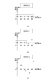
- Fig. 12 is a diagram showing an example of testing the reliability based on the behavior (load tolerance) of a positioning solution for each positioning calculation condition according to the fourth embodiment. A specific testing method is shown below.
- the positioning solution reliability determination unit 34 executes calculations under multiple positioning calculation conditions (parameter settings) in which the calculation conditions are deliberately changed so as to affect the output expected value of the valid solution of the carrier phase positioning, and determines the reliability of the positioning solution from the behavior of the positioning solution (degree of fluctuation of the positioning solution) under each positioning calculation condition.
- Examples of parameters that can be changed in the positioning calculation conditions include the number of navigation satellite systems and the number of satellites. Table 1 shows an example of setting the positioning calculation conditions.
- the positioning solution reliability determination unit 34 executes redundant positioning calculations under different conditions, and tests the reliability based on the behavior (load tolerance) of the positioning solution for each positioning calculation condition, as shown in Figures 12(a) to 12(c). Note that Figure 12(a) shows a case where the reliability is high, Figure 12(b) shows a case where the reliability is medium, and Figure 12(c) shows a case where the reliability is low.
- Fig. 13 is a flowchart showing the processing of the fifth embodiment.
- Fig. 14 is a diagram showing an example of verification using a redundant reference station according to the fifth embodiment.
- Fig. 15 is a diagram showing an example of verification using two or more redundant reference stations according to a modified example of the fifth embodiment.
- the reliability of the mobile station's positioning solution is judged by making the reference station used in the RTK-GNSS positioning calculation redundant. It is assumed that the position of the reference station used here (phase center position of the GNSS antenna of the reference station) is known.
- FIG. 14 shows an example of performing the test using one redundant reference station.
- the positioning solution reliability determination unit 34 performs an RTK-GNSS positioning calculation for the mobile station X using the observation data (correction data) acquired by the first reference station A1 and the position information of the first reference station A1, and calculates a baseline vector (relative position) from the mobile station X to the second reference station (redundant reference station) using the obtained GNSS positioning solution and observation data.
- the solution reliability determination unit 34 compares the solution of the second reference station B1 obtained as a result with the true position, thereby determining the reliability of the solution of the mobile station X.
- the mobile station X relative to the first reference station A1 becomes a reference station relative to the second mobile station B1.
- the second reference station B1 which is a redundant reference station, becomes a mobile station relative to the reference station (mobile station X).
- the positioning solution reliability determination unit 34 may use at least one or more redundant reference stations (here, the second reference station B2 and the third reference station C2) other than the first reference station A2 for the mobile station Y. That is, the absolute positioning unit 31 may perform RTK-GNSS positioning calculation for the mobile station by using each observation data acquired by a plurality of reference stations and each piece of position information of the plurality of reference stations, and the positioning solution reliability determination unit 34 may calculate the positioning solution reliability determination index by comparing these positioning calculation results.
- redundant reference stations here, the second reference station B2 and the third reference station C2
- redundant reference stations multiple nearby electronic reference points with baseline lengths within a certain distance (for example, 10 km) may be used, or in urban canyon environments in cities, reference stations installed in multiple environments where open spaces such as building rooftops can be secured may be used.
- the RTK-GNSS positioning solutions from each reference station are compared, and the reliability of the mobile station's positioning solution is judged based on the degree of agreement between them (whether the difference between the positioning solutions is within a threshold or not).
- the positioning solution reliability determination index output by the positioning solution reliability determination unit 34 may indicate a binary value indicating usable (USE) or unusable (DO NOT USE), or may indicate an index value indicating multiple stages according to the degree of reliability.
- the positioning solution reliability determination unit 34 may use a combination of multiple testing methods and output a binary positioning solution reliability determination index by ANDing the test results, or may score the index based on the results of each test. For example, when the positioning solution reliability determination unit 34 outputs a score of "3" by the first testing method and a score of "2" by the second testing method, it finally outputs a score of "5" to the composite positioning unit 35.
- the composite positioning unit 35 when the composite positioning unit 35 receives an index value (score value) from the positioning solution reliability judgment unit 34, it may use this to weight the GNSS positioning solutions in the composite positioning, or it may decide whether or not to use the positioning solution reliability judgment index (USE) depending on whether the value is above or below a threshold value (e.g., "3").
- a threshold value e.g., "3"
- the condition for passing the test may be added that the carrier phase positioning solution is a FIX solution.Furthermore, the condition for passing the test may be added that the carrier phase positioning solution is a FIX solution or a FLOAT solution.
- the absolute positioning unit effectively eliminates invisible satellites based on the satellite elevation angle, satellite signal strength (or Carrier to Noise density ratio: CN0 value), pseudorange residual, etc., and then performs redundant positioning calculations. Judgment is then made based on the results, thereby improving the accuracy of judging the reliability of the positioning solution.
- the positioning solution reliability determination unit 34 outputs the positioning solution reliability determination index, etc. along with the GNSS positioning solution to the composite positioning unit 35.
- the composite positioning unit 35 then inputs the GNSS positioning solution and the positioning solution reliability determination index, etc., for each time epoch, and performs composite positioning calculations based on the positioning solution reliability determination index (see S14, S15).
- Fig. 16(a) is a diagram showing a state transition to a dead reckoning state by the combined positioning of the conventional method
- Fig. 16(b) is a diagram showing a state transition to a dead reckoning state by the combined positioning of the method of each embodiment.
- the output unit 36 outputs data in the required data format for devices and applications that use the composite positioning solution.
- Real-time data output formats include latitude, longitude, and altitude coordinate values, ECEF coordinate system data, NMEA0183 format data, ROS (Robot Operating System) Topics data, etc. Additionally, KML (Keyhole Markup Language) format, GPX (GPS eXchange Format) format, etc. are used for composite positioning solution log data.
- the composite positioning solution output from the composite positioning unit 35 may be fed back and input to the absolute positioning unit.
- the absolute positioning unit uses the composite positioning solution as the initial position in the RTK-GNSS positioning calculation, for example.
- the composite positioning solution is not dependent on the GNSS reception environment and is continuously output even in environments where GNSS satellite signals are completely blocked, such as tunnels and under overpasses. This not only shortens the recovery time (TTFF: Time-to-First-Fix) until the RTK-GNSS fix solution is output after exiting a tunnel or passing under an overpass, but also improves the rate of obtaining a valid GNSS positioning solution in urban canyon environments where poor reception continues intermittently.
- TTFF Time-to-First-Fix
- the relative positioning unit 33 may be equipped with a sensor having performance appropriate to the requirements of the application, and the composite positioning unit 35 may select and use this sensor data.
- the present invention has an effect of maintaining high positioning accuracy in a poor reception environment of GNSS satellite signals.
- the positioning solution reliability determination unit 34 performs a positioning solution reliability determination as to whether or not the GNSS positioning solution is a valid solution close to the true value.
- the composite positioning unit 35 performs composite positioning using the GNSS positioning solution when a valid solution is obtained, and proactively transitions to dead reckoning when a valid solution is not obtained.
- the vehicle does not transition to dead reckoning (autonomous navigation) when entering a tunnel or the like without obtaining a position close to the true value by composite positioning using a GNSS positioning solution including an error due to an unsatisfactory GNSS satellite signal just before the vehicle enters a tunnel or the like, but rather proactively transitions to dead reckoning (autonomous navigation) just before the vehicle enters a tunnel or the like, so that extremely erroneous positioning is not performed even if the vehicle enters a tunnel or the like and dead reckoning continues.
- dead reckoning autonomous navigation
- the positioning device 3 can be realized by a computer and a program, but this program can also be recorded on a (non-temporary) recording medium or provided via a communication network such as the Internet.
- the CPU 301 may be multiple or may be single.
- a positioning device having a processor and performing positioning of a moving object, The processor, an absolute positioning process that performs a GNSS positioning calculation to obtain a GNSS positioning solution; a positioning solution reliability determination process for calculating a positioning solution reliability determination index by determining whether the GNSS positioning solution is a valid solution close to a true value; A composite positioning process for outputting a composite positioning solution using the GNSS positioning solution and the relative positioning based on the positioning solution reliability determination index, or outputting a positioning solution by dead reckoning without using the GNSS positioning solution; A positioning device that performs the above.
- the positioning solution reliability determination index is information indicating whether to perform combined positioning using the GNSS positioning solutions or to perform positioning without using the GNSS positioning solutions.
- the positioning solution reliability determination index is information indicating a weighting of the GNSS positioning solution when the GNSS positioning solution is used.
Landscapes
- Engineering & Computer Science (AREA)
- Radar, Positioning & Navigation (AREA)
- Remote Sensing (AREA)
- Computer Networks & Wireless Communication (AREA)
- Physics & Mathematics (AREA)
- General Physics & Mathematics (AREA)
- Position Fixing By Use Of Radio Waves (AREA)
Priority Applications (2)
| Application Number | Priority Date | Filing Date | Title |
|---|---|---|---|
| JP2025513571A JPWO2024214215A1 (https=) | 2023-04-12 | 2023-04-12 | |
| PCT/JP2023/014885 WO2024214215A1 (ja) | 2023-04-12 | 2023-04-12 | 測位装置、測位方法、及びプログラム |
Applications Claiming Priority (1)
| Application Number | Priority Date | Filing Date | Title |
|---|---|---|---|
| PCT/JP2023/014885 WO2024214215A1 (ja) | 2023-04-12 | 2023-04-12 | 測位装置、測位方法、及びプログラム |
Publications (1)
| Publication Number | Publication Date |
|---|---|
| WO2024214215A1 true WO2024214215A1 (ja) | 2024-10-17 |
Family
ID=93059151
Family Applications (1)
| Application Number | Title | Priority Date | Filing Date |
|---|---|---|---|
| PCT/JP2023/014885 Ceased WO2024214215A1 (ja) | 2023-04-12 | 2023-04-12 | 測位装置、測位方法、及びプログラム |
Country Status (2)
| Country | Link |
|---|---|
| JP (1) | JPWO2024214215A1 (https=) |
| WO (1) | WO2024214215A1 (https=) |
Citations (9)
| Publication number | Priority date | Publication date | Assignee | Title |
|---|---|---|---|---|
| JP2007107890A (ja) * | 2005-10-11 | 2007-04-26 | Geographical Survey Inst Ministry Of Land Infrastructure & Transport | 無線lan測位とgps測位とを併用した移動体の連続的測位方法及び装置、並びに移動体の連続的測位プログラム |
| WO2010001940A1 (ja) * | 2008-07-01 | 2010-01-07 | 株式会社トプコン | 位置測定方法、位置測定装置、およびプログラム |
| JP2011125128A (ja) * | 2009-12-10 | 2011-06-23 | Kyosan Electric Mfg Co Ltd | 列車制御装置 |
| JP2012007939A (ja) * | 2010-06-23 | 2012-01-12 | Aisin Aw Co Ltd | 軌跡情報生成装置、方法およびプログラム |
| JP2013076671A (ja) * | 2011-09-30 | 2013-04-25 | Casio Comput Co Ltd | 測位場所識別装置、測位場所識別方法、プログラム及び測位場所識別システム |
| JP2013171044A (ja) * | 2012-02-17 | 2013-09-02 | Samsung Electronics Co Ltd | 位置測位方法及び装置並びに電子装置 |
| JP2014071005A (ja) * | 2012-09-28 | 2014-04-21 | Jvc Kenwood Corp | 信頼度導出装置、信頼度導出方法、信頼度導出プログラム及びナビゲーション装置 |
| WO2016121058A1 (ja) * | 2015-01-29 | 2016-08-04 | 三菱電機株式会社 | 測位装置および測位方法 |
| JP2017106842A (ja) * | 2015-12-10 | 2017-06-15 | 三菱重工業株式会社 | 位置測定装置、位置測定方法及びプログラム |
-
2023
- 2023-04-12 JP JP2025513571A patent/JPWO2024214215A1/ja active Pending
- 2023-04-12 WO PCT/JP2023/014885 patent/WO2024214215A1/ja not_active Ceased
Patent Citations (9)
| Publication number | Priority date | Publication date | Assignee | Title |
|---|---|---|---|---|
| JP2007107890A (ja) * | 2005-10-11 | 2007-04-26 | Geographical Survey Inst Ministry Of Land Infrastructure & Transport | 無線lan測位とgps測位とを併用した移動体の連続的測位方法及び装置、並びに移動体の連続的測位プログラム |
| WO2010001940A1 (ja) * | 2008-07-01 | 2010-01-07 | 株式会社トプコン | 位置測定方法、位置測定装置、およびプログラム |
| JP2011125128A (ja) * | 2009-12-10 | 2011-06-23 | Kyosan Electric Mfg Co Ltd | 列車制御装置 |
| JP2012007939A (ja) * | 2010-06-23 | 2012-01-12 | Aisin Aw Co Ltd | 軌跡情報生成装置、方法およびプログラム |
| JP2013076671A (ja) * | 2011-09-30 | 2013-04-25 | Casio Comput Co Ltd | 測位場所識別装置、測位場所識別方法、プログラム及び測位場所識別システム |
| JP2013171044A (ja) * | 2012-02-17 | 2013-09-02 | Samsung Electronics Co Ltd | 位置測位方法及び装置並びに電子装置 |
| JP2014071005A (ja) * | 2012-09-28 | 2014-04-21 | Jvc Kenwood Corp | 信頼度導出装置、信頼度導出方法、信頼度導出プログラム及びナビゲーション装置 |
| WO2016121058A1 (ja) * | 2015-01-29 | 2016-08-04 | 三菱電機株式会社 | 測位装置および測位方法 |
| JP2017106842A (ja) * | 2015-12-10 | 2017-06-15 | 三菱重工業株式会社 | 位置測定装置、位置測定方法及びプログラム |
Also Published As
| Publication number | Publication date |
|---|---|
| JPWO2024214215A1 (https=) | 2024-10-17 |
Similar Documents
| Publication | Publication Date | Title |
|---|---|---|
| US11441907B2 (en) | Positioning device and positioning method | |
| JP5673071B2 (ja) | 位置推定装置及びプログラム | |
| CN109313272B (zh) | 使用速度积分的改进gnss接收器 | |
| RU2606240C2 (ru) | Навигация относительно площадки с использованием измерений расстояния | |
| EP2816374B1 (en) | Vehicle positioning in high-reflection environments | |
| US11428822B2 (en) | Methods and systems for location determination | |
| US12061275B2 (en) | Enhancing sensitivity to reflected GNSS signals | |
| WO2020202522A1 (ja) | 車両測位装置 | |
| WO2020149014A1 (ja) | 衛星選択装置、及びプログラム | |
| JP2012098185A (ja) | 方位角推定装置及びプログラム | |
| Zhang et al. | Ray-tracing correction for GNSS velocity estimation using Doppler frequency: A feasibility analysis | |
| US9423507B2 (en) | Methods and apparatuses for multipath estimation and correction in GNSS navigation systems | |
| Zhu et al. | POSMind: developing a hierarchical GNSS/SINS post-processing service system for precise position and attitude determination | |
| RU2338160C1 (ru) | Способ определения параметров навигации | |
| JP7148039B2 (ja) | 移動体情報推定装置及びプログラム | |
| JP5994237B2 (ja) | 測位装置及びプログラム | |
| JP7613922B2 (ja) | 測位精度出力システム及びそのサーバ装置 | |
| US20220244407A1 (en) | Method for Generating a Three-Dimensional Environment Model Using GNSS Measurements | |
| Dai et al. | Heading-determination using the sensor-fusion based maritime PNT Unit | |
| US20220043166A1 (en) | Determining Velocity Using a Reflected Positioning Signal | |
| WO2024214215A1 (ja) | 測位装置、測位方法、及びプログラム | |
| WO2020110996A1 (ja) | 測位装置、速度測定装置、及びプログラム | |
| JP2010112759A (ja) | 移動体位置測位装置 | |
| CN116660963B (zh) | 一种隧道群场景下车辆定位方法 | |
| Emel’yantsev et al. | State-of-the-Art Satellite Multi-Antenna Systems. Specific Features and Results of GNSS Compass Development |
Legal Events
| Date | Code | Title | Description |
|---|---|---|---|
| 121 | Ep: the epo has been informed by wipo that ep was designated in this application |
Ref document number: 23932991 Country of ref document: EP Kind code of ref document: A1 |
|
| ENP | Entry into the national phase |
Ref document number: 2025513571 Country of ref document: JP Kind code of ref document: A |
|
| WWE | Wipo information: entry into national phase |
Ref document number: 2025513571 Country of ref document: JP |
|
| NENP | Non-entry into the national phase |
Ref country code: DE |
|
| 122 | Ep: pct application non-entry in european phase |
Ref document number: 23932991 Country of ref document: EP Kind code of ref document: A1 |