WO2024209720A1 - 埋込磁石型モータ - Google Patents
埋込磁石型モータ Download PDFInfo
- Publication number
- WO2024209720A1 WO2024209720A1 PCT/JP2023/037713 JP2023037713W WO2024209720A1 WO 2024209720 A1 WO2024209720 A1 WO 2024209720A1 JP 2023037713 W JP2023037713 W JP 2023037713W WO 2024209720 A1 WO2024209720 A1 WO 2024209720A1
- Authority
- WO
- WIPO (PCT)
- Prior art keywords
- magnet
- rotor core
- holding portion
- permanent
- permanent magnet
- Prior art date
- Legal status (The legal status is an assumption and is not a legal conclusion. Google has not performed a legal analysis and makes no representation as to the accuracy of the status listed.)
- Ceased
Links
Images







Classifications
-
- H—ELECTRICITY
- H02—GENERATION; CONVERSION OR DISTRIBUTION OF ELECTRIC POWER
- H02K—DYNAMO-ELECTRIC MACHINES
- H02K1/00—Details of the magnetic circuit
- H02K1/06—Details of the magnetic circuit characterised by the shape, form or construction
- H02K1/22—Rotating parts of the magnetic circuit
- H02K1/27—Rotor cores with permanent magnets
- H02K1/2706—Inner rotors
- H02K1/272—Inner rotors the magnetisation axis of the magnets being perpendicular to the rotor axis
- H02K1/274—Inner rotors the magnetisation axis of the magnets being perpendicular to the rotor axis the rotor consisting of two or more circumferentially positioned magnets
- H02K1/2753—Inner rotors the magnetisation axis of the magnets being perpendicular to the rotor axis the rotor consisting of two or more circumferentially positioned magnets the rotor consisting of magnets or groups of magnets arranged with alternating polarity
- H02K1/276—Magnets embedded in the magnetic core, e.g. interior permanent magnets [IPM]
- H02K1/2766—Magnets embedded in the magnetic core, e.g. interior permanent magnets [IPM] having a flux concentration effect
-
- H—ELECTRICITY
- H02—GENERATION; CONVERSION OR DISTRIBUTION OF ELECTRIC POWER
- H02K—DYNAMO-ELECTRIC MACHINES
- H02K2213/00—Specific aspects, not otherwise provided for and not covered by codes H02K2201/00 - H02K2211/00
- H02K2213/03—Machines characterised by numerical values, ranges, mathematical expressions or similar information
Definitions
- This disclosure relates to embedded magnet motors.
- the gap that connects from the magnet holes to the outer peripheral surface of the rotor core will be referred to as an open gap.
- This disclosure has been made in consideration of the above circumstances, and its purpose is to provide an embedded magnet motor with an open-type gap that can suppress demagnetization of the permanent magnets while suppressing torque reduction and cost increases.
- An embedded magnet motor includes a permanent magnet inserted into a magnet hole provided in a rotor core, an open gap portion connecting the magnet hole to the outer peripheral surface of the rotor core, and a magnet holding portion that contacts the side surface of the permanent magnet and forms a closed gap portion on the side surface that is not connected to the outer peripheral surface of the rotor core.
- FIG. 2 is a schematic diagram showing an embedded magnet motor according to an embodiment as viewed from the axial direction;
- FIG. 2 is an enlarged view of region II in FIG. 1 .
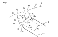
- FIG. 3 is an enlarged view of region III in FIG. 2 .
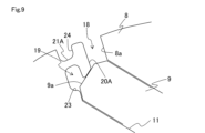
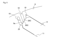
- a diagram showing the relationship between the holding part angle and torque and demagnetization rate Diagram showing the relationship between the holding part angle and the magnetic path FIG. 1 showing another example of the shape of the magnet holder Figure 2 showing another example of the shape of the magnet holder Figure 3 showing other examples of the shape of the magnet holder Figure 4 showing other examples of the shape of the magnet holder Figure 5 showing other examples of magnet holder shapes
- the embedded magnet motor 1 of this embodiment includes a stator 2, a rotor 3, and a shaft 4.
- the direction along the rotation axis (J) of the rotor 3 will be referred to as the axial direction
- the direction around the rotation axis (J) will be referred to as the circumferential direction
- the direction from the rotation axis (J) along the outer periphery of the rotor 3 will be referred to as the radial direction.
- the stator 2 and rotor 3 are housed in a case (not shown), and the case is provided with bearing members such as bearings that rotatably support the shaft 4.
- the stator 2 comprises a stator core 5 formed in a generally hollow cylindrical shape by stacking electromagnetic steel sheets of a prescribed shape in the axial direction, and coils 7 inserted into slots 6 formed on the inner peripheral surface of the stator core 5 as shown in FIG. 2.
- a plurality of slots 6 are formed at prescribed intervals in the circumferential direction, penetrating the inner peripheral surface of the stator 2 in the axial direction.
- the coils 7 are fixed to the stator core 5 by winding a wire such as an enameled wire into the slots 6, or by fitting a wire that has already been wound in advance into the slots 6. Note that a configuration using a bus bar may also be used as the coils 7.
- the rotor 3 includes a rotor core 8 formed into a roughly hollow cylindrical shape, for example, by stacking electromagnetic steel sheets punched into a predetermined shape in the axial direction, and a number of permanent magnets 9 arranged inside the rotor core 8.
- the shaft 4 is fixed in the hollow portion of the rotor core 8, for example, by press fitting, and rotates integrally with the rotor 3 relative to the stator core 5 around the rotation axis (J).
- the permanent magnets 9 are formed in a generally rectangular shape when viewed from the axial direction of the rotor core 8, with relatively short short sides and relatively long long sides.
- the permanent magnets 9 are generally equal in length in the short direction, while the permanent magnets 9 arranged on the inner periphery of the multi-layer structure are longer in the long direction.
- Each permanent magnet 9 is magnetized along the short direction.
- the permanent magnets 9 have a shape with flat chamfered corners, but this shape is one example, and it is also possible to use a shape with unchamfered corners or a shape with curved chamfered corners.
- These permanent magnets 9 are arranged in pairs at positions that are linearly symmetrical with respect to an imaginary line (VL) passing through the rotation axis (J), in a roughly V-shape with the distance between them being relatively short on the radially inner side and relatively long on the radially outer side.
- a pair of permanent magnets 9 are arranged side by side along the radial direction.
- a structure in which a pair of permanent magnets 9 are arranged side by side in the radial direction will be referred to as a multi-layer structure for convenience, and the multiple permanent magnets 9 that make up this multi-layer structure will also be referred to as a magnet group for convenience.
- one multi-layer magnet group is made up of four permanent magnets 9.
- the magnet groups are arranged at eight equal positions around the rotor core 8 in the circumferential direction. Adjacent magnet groups are arranged so that the magnetization directions of the permanent magnets 9 are alternately opposite. Therefore, the embedded magnet motor 1 has eight magnetic poles 10 formed at equal positions around the circumference.
- the structure shown in FIG. 1 and FIG. 2 is only an example, and the shape and number of the slots 6, the number and arrangement of the magnetic poles 10 of the rotor 3, the shape of the permanent magnets 9, etc. are not limited to this.
- the permanent magnets 9 are inserted into a number of magnet holes 11 formed in the rotor core 8.
- Each magnet hole 11 is connected to a gap for forming a flux barrier.
- each magnet hole 11 is connected to an inner gap 12 on the radially inner side, that is, on the imaginary line (VL) side which is the center of the magnetic pole 10.
- This inner gap 12 is a closed type that is not connected to the outer circumferential surface of the rotor core 8.
- a first bridge portion 13 is formed along the imaginary line (VL) between the inner gaps 12 which are on the outer circumferential side in the multi-layer structure.
- a second bridge portion 14 is formed along the imaginary line (VL) between the inner gaps 12 which are on the inner circumferential side in the multi-layer structure.
- each magnet hole 11 located on the inner circumference side in the multi-layer structure is connected to the outer void 15 on the radially outer side, that is, on the side opposite to the imaginary line (VL).
- An outer periphery bridge portion 16 is formed on the outer periphery side of the outer void 15.
- the outer void 15 is a closed type that is not connected to the outer periphery surface of the rotor core 8.
- the inner void 12 and the outer void 15 each have a protrusion 17 formed therein that extends along the side of the permanent magnet 9 and contacts the permanent magnet 9 to hold the permanent magnet 9 in a predetermined position.
- the magnet holes 11 located on the outer periphery side in the multi-layer structure are connected radially outward to an open gap 18 that connects from the magnet holes 11 to the outer periphery of the rotor core 8 as shown in Figure 3, and to a closed gap 19 that is connected to the magnet holes 11 but not to the outer periphery of the rotor core 8.
- a gap is intentionally provided between the permanent magnets 9 and the magnet holes 11 to make the drawing easier to see.
- the magnet holding portion 20 is provided to separate the open gap portion 18 and the closed gap portion 19.
- the magnet holding portion 20 is connected to a connecting bridge portion 21 that extends from a portion of the outer circumferential surface of the rotor core 8, and on the side of the permanent magnet 9 facing the open gap portion 18, a closed gap portion 19 is formed that is surrounded by the magnet holding portion 20, connecting bridge portion 21, and rotor core 8 and is connected to the magnet hole 11, but is not connected to the outer circumferential surface of the rotor core 8.
- the short side surface of the permanent magnet 9 that is in contact with the magnet holding portion 20 will be referred to as the short side surface 9a for convenience.
- the magnet holding portion 20 is formed so that its width (W1) is equal to or smaller than the width (W2) of the short side surface 9a of the permanent magnet 9, and is in contact with the short side surface 9a within a predetermined width (W3). Furthermore, on the open-type gap portion 18 side, the magnet holding portion 20 is in contact with the short side surface 9a at a position that does not overlap the chamfered portion 22a of the permanent magnet 9. Therefore, between the contact position of the magnet holding portion 20 and the inner surface of the magnet hole 11, there is a gap that is equal to or larger than the apparent width (W4) of the chamfered portion 22a when viewed from the short side surface 9a.
- the magnet holding portion 20 contacts the short side surface 9a on the closed gap portion 19 side, inside the intersection point between the short side surface 9a and the chamfered portion 22b. Therefore, the short side surface 9a of the permanent magnet 9 is exposed to the closed gap portion 19 at a predetermined width (W5) between the contact position of the magnet holding portion 20 and the chamfered portion 22b.
- the magnet holding portion 20 is formed in a generally rectangular shape except for the portion that comes into contact with the permanent magnet 9.
- the corners of the magnet holding portion 20, the connection portion between the magnet holding portion 20 and the connecting bridge portion 21, and the connection portion between the connecting bridge portion 21 and the rotor core 8 are chamfered into a curved shape by fillet processing. This reduces the concentration of stress at the corners and connections.
- the magnet holding portion 20 is formed so as to be generally parallel to the wall surface 8a of the rotor core 8 that forms the open gap portion 18, and the wall surface 8b of the rotor core 8 that forms the closed gap portion 19.
- auxiliary holding portion 23 in which a portion of the rotor core 8 protrudes and contacts the chamfered portion 22b of the permanent magnet 9, stress applied to the magnet holding portion 20 and the connecting bridge portion 21 is reduced.
- the width (W1) of the magnet holding portion 20, the width (W3) of the contact with the short side surface 9a, and the positional relationship and range of contact with the short side surface 9a are only examples, and can be set appropriately based on the size and shape of the permanent magnet 9, and so as to have the strength to hold the permanent magnet 9.
- the gap 103 is narrowed so that it also serves as the holding structure 104 for the permanent magnet 9, demagnetization is suppressed, but there is a problem that the torque decreases. Furthermore, if many gaps are provided around the permanent magnet 9, the inductance decreases and the torque decreases. Furthermore, filling the gap 103 with a non-magnetic material increases costs.
- a magnet holding portion 20 is provided that contacts the side surface of the permanent magnet 9 and forms a closed gap portion 19 on said side surface that is not connected to the outer peripheral surface of the rotor core 8. This suppresses leakage magnetic flux as shown by the dashed line, reduces magnetic flux bulging, and suppresses demagnetization. This is because the magnetic path of the gap portion is shorter than when only the open gap portion 18 is provided.
- Figure 5 shows the simulation results of the demagnetization factor distribution in the conventional structure example and the implemented structure example. Note that in Figure 5, the region is divided into regions where the demagnetization factor is less than 20% (R1), where the demagnetization factor is in the range of 20% to 30% (R2), where the demagnetization factor is in the range of 30% to 40% (R3), and where the demagnetization factor exceeds 40% (R4).
- the region (R4) where the demagnetization rate exceeds 40% is significantly smaller than in the conventional structure, and demagnetization is suppressed.
- the demagnetization rate in the conventional structure is X [%] and the torque is Y [Nm]
- the demagnetization rate is smaller than X and the torque is greater than Y, and both the demagnetization rate and the torque were improved.
- the demagnetization rate represented by X was calculated based on the rate of decrease in the peak value of the induced voltage before and after demagnetization.
- the embedded magnet motor 1 comprises a permanent magnet 9 inserted in a magnet hole 11 provided in a rotor core 8, an open gap 18 connecting from the magnet hole 11 to the outer circumferential surface of the rotor core 8, and a magnet holding portion 20 that contacts a side surface of the permanent magnet 9 and forms a closed gap 19 on said side surface that is not connected to the outer circumferential surface of the rotor core 8.
- a configuration that includes the open gap 18 leakage flux can be reduced and swelling caused when leakage flux flows can be suppressed, and demagnetization of the permanent magnet 9 can be suppressed while suppressing a decrease in torque and an increase in cost.
- the magnet holding portion 20 contacts the radially outer side surface of the permanent magnet 9 when viewed from the axial direction which is the center of rotation of the rotor core 8. This makes it possible to suppress the demagnetization rate of the permanent magnet 9 in a portion that is easily demagnetized.
- the permanent magnet 9 is formed in a shape having a relatively short side surface and a relatively long side surface when viewed from the axial direction which is the center of rotation of the rotor core 8, and the magnet holding portion 20 contacts the short side surface of the permanent magnet 9. This makes it possible to suppress the demagnetization rate of the parts of the permanent magnet 9 which are easily demagnetized.
- multiple permanent magnets 9 are arranged in a radial direction of the rotor core 8, and the magnet holding portion 20 is provided corresponding to at least one of the multiple permanent magnets 9. In this embodiment, it is provided corresponding to the permanent magnet 9 that is the outermost radial magnet. This makes it possible to suppress the demagnetization rate at the position where the open gap portion 18 is expected to be provided.
- the magnet holding portion 20 is not limited to the shape shown in FIG. 3, and can have other shapes.
- the angle ( ⁇ ) between a line segment (L1) along the short side surface 9a of the permanent magnet 9 when viewed from the axial direction and a line segment (L2) along the straight portion of the side surface of the magnet holding portion 20 on the open gap portion 18 side can be changed.
- the angle ( ⁇ ) between the line segments (L1) and (L2) will be referred to as the holding portion angle for convenience, and the center side of the magnetic pole 10 will be described as 0 degrees.
- the line segment (L2) is generally parallel to the wall surface 8a of the rotor core 8 that forms the open gap portion 18, and the line segment (L3) along the straight portion of the side surface of the magnet holding portion 20 on the closed gap portion 19 side is generally parallel to the wall surface 8b of the rotor core 8 that forms the closed gap portion 19.
- the line segments (L2) and (L3) are generally parallel.
- Figure 7 shows the relationship between torque and demagnetization factor when the retaining part angle is changed from 5 degrees to 105 degrees.
- point (P5) in Figure 7 shows the result when the retaining part angle is 5 degrees
- point (P15) shows the result when the retaining part angle is 15 degrees
- the auxiliary line placed at the position where the demagnetization factor is X [%] and the auxiliary line placed at the position where the torque is Y [Nm] both show the demagnetization factor and torque in the conventional structure example shown in Figure 4.
- the torque starts to decrease when the holding portion angle exceeds 75 degrees, and decreases significantly at 105 degrees, but this is not thought to be a problem with the holding portion angle.
- the holding portion angle is set to approximately 105 degrees, as shown by the dashed line in Figure 8, a narrow region (R10) is formed between the holding portion angle and the outer gap portion 15 located on the inner circumference side of the multi-layer structure, narrowing the q-axis magnetic path, which is thought to cause magnetic saturation.
- a magnetic path can be secured, for example by providing a magnet holding portion 20 corresponding to the inner periphery permanent magnet 9 in a multi-layer structure, it is believed that the torque can be improved even if the holding portion angle is set to 105 degrees.
- the demagnetization rate can be suppressed by setting the holding portion angle in the range of approximately 5 degrees to 105 degrees, more preferably in the range of approximately 5 degrees to 90 degrees, and even more preferably in the range of approximately 5 degrees to 80 degrees.
- the shape of the magnet holding portion 20 can also be modified in addition to the above-mentioned holding portion angle.
- a connecting bridge portion 21A can be positioned between the short side surface 9a of the permanent magnet 9 and the outer peripheral surface of the rotor core 8, and a magnet holding portion 20A connected to the connecting bridge portion 21A can be provided.
- the connecting bridge portion 21A can also be configured to have an auxiliary gap portion 24 recessed from the outer peripheral surface of the rotor core 8.
- a magnet holder 20B that forms multiple closed-type gaps 19 can be provided on the short side surface 9a of one permanent magnet 9.
- a configuration can be made in which multiple magnet holding portions 20C are provided on the short side surface 9a of one permanent magnet 9, each forming a closed-type gap portion 19.
- this configuration it is possible to obtain the same effects as the above-mentioned embodiment structure example, such as suppressing demagnetization of the permanent magnet 9 while suppressing torque reduction and cost increase in a configuration with an open-type gap portion 18.
- a magnet holding section 20E can be provided in the conventional configuration shown in FIG. 4.
- the conventional holding structure 104 is considered to be provided in a state capable of holding the permanent magnet 9
- the degree of freedom in designing the strength calculation, shape, dimensions, contact area, etc. of the magnet holding section 20E can be increased.
- the shape examples shown in FIG. 9 to FIG. 13 can be combined with each other to the extent that they do not conflict. They can also be applied to permanent magnets 9 with shapes that do not have chamfered corners.
Landscapes
- Engineering & Computer Science (AREA)
- Power Engineering (AREA)
- Permanent Field Magnets Of Synchronous Machinery (AREA)
Priority Applications (2)
| Application Number | Priority Date | Filing Date | Title |
|---|---|---|---|
| CN202380095887.4A CN120858507A (zh) | 2023-04-03 | 2023-10-18 | 磁铁埋入型马达 |
| DE112023006110.6T DE112023006110T5 (de) | 2023-04-03 | 2023-10-18 | Motor mit eingebetteten magneten |
Applications Claiming Priority (2)
| Application Number | Priority Date | Filing Date | Title |
|---|---|---|---|
| JP2023060182A JP2024147267A (ja) | 2023-04-03 | 2023-04-03 | 埋込磁石型モータ |
| JP2023-060182 | 2023-04-03 |
Publications (1)
| Publication Number | Publication Date |
|---|---|
| WO2024209720A1 true WO2024209720A1 (ja) | 2024-10-10 |
Family
ID=92973090
Family Applications (1)
| Application Number | Title | Priority Date | Filing Date |
|---|---|---|---|
| PCT/JP2023/037713 Ceased WO2024209720A1 (ja) | 2023-04-03 | 2023-10-18 | 埋込磁石型モータ |
Country Status (4)
| Country | Link |
|---|---|
| JP (1) | JP2024147267A (https=) |
| CN (1) | CN120858507A (https=) |
| DE (1) | DE112023006110T5 (https=) |
| WO (1) | WO2024209720A1 (https=) |
Citations (4)
| Publication number | Priority date | Publication date | Assignee | Title |
|---|---|---|---|---|
| JP2012205472A (ja) * | 2011-03-28 | 2012-10-22 | Toyota Industries Corp | 回転電機の永久磁石埋設型回転子及び回転電機 |
| WO2017061244A1 (ja) * | 2015-10-06 | 2017-04-13 | 三菱電機株式会社 | 回転電機 |
| JP2021158795A (ja) * | 2020-03-26 | 2021-10-07 | 株式会社アイシン | モータ、アクチュエータ、及びモータに備えられるロータの製造方法 |
| WO2022044090A1 (ja) * | 2020-08-24 | 2022-03-03 | 株式会社 東芝 | ロータ |
-
2023
- 2023-04-03 JP JP2023060182A patent/JP2024147267A/ja active Pending
- 2023-10-18 CN CN202380095887.4A patent/CN120858507A/zh active Pending
- 2023-10-18 WO PCT/JP2023/037713 patent/WO2024209720A1/ja not_active Ceased
- 2023-10-18 DE DE112023006110.6T patent/DE112023006110T5/de active Pending
Patent Citations (4)
| Publication number | Priority date | Publication date | Assignee | Title |
|---|---|---|---|---|
| JP2012205472A (ja) * | 2011-03-28 | 2012-10-22 | Toyota Industries Corp | 回転電機の永久磁石埋設型回転子及び回転電機 |
| WO2017061244A1 (ja) * | 2015-10-06 | 2017-04-13 | 三菱電機株式会社 | 回転電機 |
| JP2021158795A (ja) * | 2020-03-26 | 2021-10-07 | 株式会社アイシン | モータ、アクチュエータ、及びモータに備えられるロータの製造方法 |
| WO2022044090A1 (ja) * | 2020-08-24 | 2022-03-03 | 株式会社 東芝 | ロータ |
Also Published As
| Publication number | Publication date |
|---|---|
| CN120858507A (zh) | 2025-10-28 |
| JP2024147267A (ja) | 2024-10-16 |
| DE112023006110T5 (de) | 2026-01-15 |
Similar Documents
| Publication | Publication Date | Title |
|---|---|---|
| JP6806352B2 (ja) | 回転電機、回転子鉄心の製造方法 | |
| JP5935615B2 (ja) | 回転電機のロータ | |
| JP6429992B2 (ja) | 永久磁石埋込型電動機、送風機および冷凍空調機 | |
| EP3151386A1 (en) | Permanent magnet rotor and permanent magnet rotating electrical machine | |
| US20140210296A1 (en) | Rotor for permanent magnet type motor, method of manufacturing rotor for permanent magnet type motor, and permanent magnet type motor | |
| JP7299531B2 (ja) | 回転子、モータ | |
| JP2009118687A (ja) | 永久磁石式回転機 | |
| KR101473086B1 (ko) | 회전 전기기계 | |
| CN114303302B (zh) | 永磁铁埋入型马达 | |
| JP7401380B2 (ja) | 永久磁石電動機 | |
| WO2024209720A1 (ja) | 埋込磁石型モータ | |
| JP7737872B2 (ja) | 永久磁石電動機 | |
| JP6949283B1 (ja) | 同期電動機 | |
| CN113206564A (zh) | 旋转电机 | |
| JP7814523B2 (ja) | ロータコア、ロータ、回転電機及びロータコアの設計方法 | |
| JP7401381B2 (ja) | 永久磁石電動機 | |
| JP2025083931A (ja) | 回転電機 | |
| KR20250150636A (ko) | 로터 코어, 로터, 회전 전기 기계 및 로터 코어의 설계 방법 | |
| JP2018107899A (ja) | 回転子 | |
| WO2026018480A1 (ja) | 永久磁石ロータおよび回転電機 | |
| JP2023102516A (ja) | ロータ及び回転電機 | |
| WO2023105701A1 (ja) | 回転電機の回転子 | |
| JP2019176738A (ja) | 回転電機、回転子鉄心の製造方法 |
Legal Events
| Date | Code | Title | Description |
|---|---|---|---|
| 121 | Ep: the epo has been informed by wipo that ep was designated in this application |
Ref document number: 23932130 Country of ref document: EP Kind code of ref document: A1 |
|
| WWE | Wipo information: entry into national phase |
Ref document number: 202380095887.4 Country of ref document: CN |
|
| WWP | Wipo information: published in national office |
Ref document number: 202380095887.4 Country of ref document: CN |
|
| WWE | Wipo information: entry into national phase |
Ref document number: 112023006110 Country of ref document: DE |
|
| WWP | Wipo information: published in national office |
Ref document number: 112023006110 Country of ref document: DE |
|
| 122 | Ep: pct application non-entry in european phase |
Ref document number: 23932130 Country of ref document: EP Kind code of ref document: A1 |