WO2024209556A1 - 香味吸引物品 - Google Patents
香味吸引物品 Download PDFInfo
- Publication number
- WO2024209556A1 WO2024209556A1 PCT/JP2023/013981 JP2023013981W WO2024209556A1 WO 2024209556 A1 WO2024209556 A1 WO 2024209556A1 JP 2023013981 W JP2023013981 W JP 2023013981W WO 2024209556 A1 WO2024209556 A1 WO 2024209556A1
- Authority
- WO
- WIPO (PCT)
- Prior art keywords
- flavor
- wrapper
- tip
- plug
- inhalation article
- Prior art date
- Legal status (The legal status is an assumption and is not a legal conclusion. Google has not performed a legal analysis and makes no representation as to the accuracy of the status listed.)
- Ceased
Links
Images






Classifications
-
- A—HUMAN NECESSITIES
- A24—TOBACCO; CIGARS; CIGARETTES; SIMULATED SMOKING DEVICES; SMOKERS' REQUISITES
- A24D—CIGARS; CIGARETTES; TOBACCO SMOKE FILTERS; MOUTHPIECES OF CIGARS OR CIGARETTES; MANUFACTURE OF TOBACCO SMOKE FILTERS OR MOUTHPIECES
- A24D1/00—Cigars; Cigarettes
- A24D1/20—Cigarettes specially adapted for simulated smoking devices
-
- A—HUMAN NECESSITIES
- A24—TOBACCO; CIGARS; CIGARETTES; SIMULATED SMOKING DEVICES; SMOKERS' REQUISITES
- A24B—MANUFACTURE OR PREPARATION OF TOBACCO FOR SMOKING OR CHEWING; TOBACCO; SNUFF
- A24B15/00—Chemical features or treatment of tobacco; Tobacco substitutes, e.g. in liquid form
- A24B15/10—Chemical features of tobacco products or tobacco substitutes
- A24B15/16—Chemical features of tobacco products or tobacco substitutes of tobacco substitutes
-
- A—HUMAN NECESSITIES
- A24—TOBACCO; CIGARS; CIGARETTES; SIMULATED SMOKING DEVICES; SMOKERS' REQUISITES
- A24B—MANUFACTURE OR PREPARATION OF TOBACCO FOR SMOKING OR CHEWING; TOBACCO; SNUFF
- A24B15/00—Chemical features or treatment of tobacco; Tobacco substitutes, e.g. in liquid form
- A24B15/18—Treatment of tobacco products or tobacco substitutes
- A24B15/28—Treatment of tobacco products or tobacco substitutes by chemical substances
- A24B15/30—Treatment of tobacco products or tobacco substitutes by chemical substances by organic substances
- A24B15/32—Treatment of tobacco products or tobacco substitutes by chemical substances by organic substances by acyclic compounds
-
- A—HUMAN NECESSITIES
- A24—TOBACCO; CIGARS; CIGARETTES; SIMULATED SMOKING DEVICES; SMOKERS' REQUISITES
- A24D—CIGARS; CIGARETTES; TOBACCO SMOKE FILTERS; MOUTHPIECES OF CIGARS OR CIGARETTES; MANUFACTURE OF TOBACCO SMOKE FILTERS OR MOUTHPIECES
- A24D1/00—Cigars; Cigarettes
- A24D1/02—Cigars; Cigarettes with special covers
-
- A—HUMAN NECESSITIES
- A24—TOBACCO; CIGARS; CIGARETTES; SIMULATED SMOKING DEVICES; SMOKERS' REQUISITES
- A24D—CIGARS; CIGARETTES; TOBACCO SMOKE FILTERS; MOUTHPIECES OF CIGARS OR CIGARETTES; MANUFACTURE OF TOBACCO SMOKE FILTERS OR MOUTHPIECES
- A24D3/00—Tobacco smoke filters, e.g. filter tips or filtering inserts; Filters specially adapted for simulated smoking devices; Mouthpieces of cigars or cigarettes
- A24D3/04—Tobacco smoke filters characterised by their shape or structure
-
- A—HUMAN NECESSITIES
- A24—TOBACCO; CIGARS; CIGARETTES; SIMULATED SMOKING DEVICES; SMOKERS' REQUISITES
- A24D—CIGARS; CIGARETTES; TOBACCO SMOKE FILTERS; MOUTHPIECES OF CIGARS OR CIGARETTES; MANUFACTURE OF TOBACCO SMOKE FILTERS OR MOUTHPIECES
- A24D3/00—Tobacco smoke filters, e.g. filter tips or filtering inserts; Filters specially adapted for simulated smoking devices; Mouthpieces of cigars or cigarettes
- A24D3/17—Filters specially adapted for simulated smoking devices
-
- A—HUMAN NECESSITIES
- A24—TOBACCO; CIGARS; CIGARETTES; SIMULATED SMOKING DEVICES; SMOKERS' REQUISITES
- A24F—SMOKERS' REQUISITES; MATCH BOXES; SIMULATED SMOKING DEVICES
- A24F40/00—Electrically operated smoking devices; Component parts thereof; Manufacture thereof; Maintenance or testing thereof; Charging means specially adapted therefor
- A24F40/10—Devices using liquid inhalable precursors
-
- A—HUMAN NECESSITIES
- A24—TOBACCO; CIGARS; CIGARETTES; SIMULATED SMOKING DEVICES; SMOKERS' REQUISITES
- A24F—SMOKERS' REQUISITES; MATCH BOXES; SIMULATED SMOKING DEVICES
- A24F40/00—Electrically operated smoking devices; Component parts thereof; Manufacture thereof; Maintenance or testing thereof; Charging means specially adapted therefor
- A24F40/20—Devices using solid inhalable precursors
-
- A—HUMAN NECESSITIES
- A24—TOBACCO; CIGARS; CIGARETTES; SIMULATED SMOKING DEVICES; SMOKERS' REQUISITES
- A24F—SMOKERS' REQUISITES; MATCH BOXES; SIMULATED SMOKING DEVICES
- A24F40/00—Electrically operated smoking devices; Component parts thereof; Manufacture thereof; Maintenance or testing thereof; Charging means specially adapted therefor
- A24F40/40—Constructional details, e.g. connection of cartridges and battery parts
Definitions
- the present invention relates to a flavor inhalation article.
- heated flavor inhalers that provide users with tobacco flavor by heating the tobacco filler without burning it have been used instead of combustion-type flavor inhalers for cigarettes and the like.
- the heated flavor inhaler contains a tobacco filler together with an aerosol source.
- the tobacco filler is heated by the heated flavor inhaler, the moisture and aerosol source in the tobacco filler vaporize, and the tobacco flavor components migrate from the tobacco filler into the gas, generating an aerosol (i.e., tobacco vapor).
- a typical example of a heated flavor inhaler is an electrically heated flavor inhaler that includes a flavor inhalation article that includes a tobacco filler and a wrapper wrapped around the tobacco filler, and a heating device for electrically heating the flavor inhalation article (see Patent Document 1).
- the present invention aims to provide a technology that can suppress the increase over time in the diameter of a tip plug placed at the tip of a flavor inhalation article.
- a tip plug is located at one end of the flavor inhalation article and includes a first filter medium, a first aerosol source supported by the first filter medium, and a first wrapper wrapped around the first filter medium; a filter plug located at the other end of the flavor inhalation article and including a second filter medium; a flavor generating section located between the tip plug and the filter plug and including a flavor source; a second wrapper around the tip plug and the flavor generating section and connecting them;
- a flavor inhalation article is provided in which the tip portion of the wrapper complex including the first wrapper and the second wrapper, which is located at the most distal end of the one end side of the flavor inhalation article, has a basis weight of 80 g/m2 or more , or the contact angle of the surface in contact with the first filter material is 60° or more.
- the present invention provides a technology that can suppress the increase over time in diameter of the tip plug placed at the tip of the flavor inhalation article.
- FIG. 1 is a schematic cross-sectional side view showing a tobacco stick according to a first embodiment.
- FIG. 2 is a cross-sectional view showing an example of a tip plug.
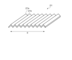
- FIG. 3 is a schematic diagram showing an example of the first filter medium.
- FIG. 4 is an exploded perspective view showing a tobacco stick according to the second embodiment.
- FIG. 5 is an exploded perspective view showing a tobacco stick according to the third embodiment.
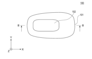
- FIG. 6A is a schematic front view showing an example of an aerosol generating device.
- FIG. 6B is a schematic top view of the aerosol generating device shown in FIG. 6A.
- FIG. 6C is a schematic bottom view of the aerosol generating device shown in FIG. 6A.
- FIG. 7 is a cross-sectional view taken along line III-III of the aerosol generating device shown in FIG. 6B.
- FIG. 8 is a graph showing the relationship between the number of days stored and the amount of increase in circumference of the end plug.
- [1] Flavor Inhalation Article In the latter half of the inhalation period, the amount of aerosol (smoke) of the heated flavor inhaler decreases with an increase in the number of inhalations, and the user feels a decrease in the inhalation response. For this reason, the inventors arranged a tip plug on the tip side (i.e., the side opposite to the mouthpiece) of the flavor inhalation article, and made the filter material of the tip plug carry an additional aerosol source. At this time, the inventors encountered a new problem that the diameter of the tip plug increases during storage. The increase in the diameter of the tip plug may lead to the rupture of the tip plug or may cause a problem in the manufacturability when connecting the tip plug to other components of the flavor inhalation article. Therefore, the present invention aims to provide a technology that can suppress the increase in the diameter of the tip plug over time.
- a tip plug is located at one end of the flavor inhalation article and includes a first filter medium, a first aerosol source supported by the first filter medium, and a first wrapper wrapped around the first filter medium; a filter plug located at the other end of the flavor inhalation article and including a second filter medium; a flavor generating section located between the tip plug and the filter plug and including a flavor source; a second wrapper around the tip plug and the flavor generating section and connecting them;
- a flavor inhalation article is provided in which the tip portion of the wrapper complex including the first wrapper and the second wrapper, which is located at the most distal end of the one end side of the flavor inhalation article, has a basis weight of 80 g/m2 or more , or the contact angle of the surface in contact with the first filter material is 60° or more.
- the above-mentioned flavor inhalation article containing a tobacco flavor source as a flavor source is also referred to as a "tobacco stick.”
- tobacco stick according to the first embodiment will be described with reference to FIG. 1.
- a tobacco stick 200 includes, in order from the tip side (i.e., the side opposite to the mouthpiece), a tip plug 210, a flavor generating section 220, a hollow tube section 230, a hollow filter section 240, and a filter plug 250. These five components are connected by a tipping wrapper 270. That is, in the first embodiment, the tipping wrapper 270 connects the tip plug 210 and the flavor generating section 220, and further connects the filter plug 250 to the flavor generating section 220. In Fig. 1, the hollow tube section 230 and the hollow filter section 240 can each be omitted.
- the tip plug wrap 212 around which the first filter material 211 is wrapped around the tip plug 210 corresponds to the "first wrapper”
- the tipping wrapper 270 corresponds to the "second wrapper.” Therefore, the tip plug wrap 212 and the tipping wrapper 270 form a "wrapper complex.”
- the tobacco stick 200 is characterized in that "the tip portion (hereinafter simply referred to as the "tip portion") located at the most distal end of one end of the tobacco stick 200 in the wrapper composite body has a basis weight of 80 g/m 2 or more, or the contact angle of the surface in contact with the first filter medium 211 (i.e., the inner surface of the tip plug wrap 212) is 60° or more.
- the tobacco stick 200 has such a characteristic, it is possible to suppress an increase over time in the diameter of the tip plug 210 arranged at the tip of the tobacco stick 200.
- the upper limit of the basis weight of the tip portion is not particularly limited, but is, for example, 200 g/m 2 or less.
- the upper limit of the contact angle of the tip portion is not particularly limited, but is, for example, 120° or less. That is, according to one example, the tobacco stick 200 can be characterized in that the tip portion has a basis weight of 80 to 200 g/m 2 , or the contact angle of the surface in contact with the first filter medium 211 is 60 to 120°.
- the tip plug is connected to other components of the flavor inhalation article to manufacture the flavor inhalation article, but after manufacture of the tip plug, it is not connected to the other components immediately, but is stored for a while or transported to another factory. Therefore, if the increase in diameter of the tip plug 210 over time is suppressed, the tip plug can be prevented from bursting. Furthermore, if the increase in diameter of the tip plug 210 over time is suppressed, manufacturing suitability problems that arise when connecting the tip plug to other components of the flavor inhalation article due to differences in diameter between the tip plug and the other components can be solved.
- the "tip portion of the wrapper complex located at the most forward end of one end of the tobacco stick 200" is shown as DP in Figure 1.
- the tip portion of the tipping wrapper 270 exposes the tip plug wrap 212 at the tip portion.
- the tip portion does not include the tipping wrapper 270 and is composed only of the tip plug wrap 212 (see Figure 1).
- the tipping wrapper 270 may cover the tip of the tip plug wrap 212 without exposing the tip portion of the tip plug wrap 212.
- the tipping wrapper 270 may cover the entire portion of the tip plug wrap 212 located at the tip portion.
- the tip portion is composed of the tipping wrapper 270 and the tip plug wrap 212.
- the basis weight of the tip portion can be calculated by adding up the basis weight of the tipping wrapper 270 and the basis weight of the tip plug wrap 212.
- the above-mentioned tip portion preferably has a basis weight of 80 g/m 2 or more, or the contact angle of the surface in contact with the first filter medium 211 (i.e., the inner surface of the tip plug wrap 212) is 80 ° or more.
- the above-mentioned tip portion more preferably has a basis weight of 80 g/m 2 or more, and the contact angle of the surface in contact with the first filter medium 211 is 60 ° or more.
- the above-mentioned tip portion more more preferably has a basis weight of 80 g/m 2 or more, and the contact angle of the surface in contact with the first filter medium 211 is 80 ° or more. According to these preferred aspects, the increase in the diameter of the tip plug 210 over time can be more effectively suppressed.
- the upper limit of the basis weight of the tip portion is, for example, 200 g/m 2 or less.
- the upper limit of the contact angle of the tip portion is, for example, 120 ° or less. That is, the above-mentioned tip portion preferably has a basis weight of 80 to 200 g/m 2 or a contact angle of 80 to 120° on the surface in contact with the first filter medium 211.
- the above-mentioned tip portion more preferably has a basis weight of 80 to 200 g/m 2 and a contact angle of 60 to 120° on the surface in contact with the first filter medium 211.
- the above-mentioned tip portion more preferably has a basis weight of 80 to 200 g/m 2 and a contact angle of 80 to 120° on the surface in contact with the first filter medium 211.
- the tip portion described above has a thickness of, for example, 35 to 250 ⁇ m, preferably 50 to 200 ⁇ m, and more preferably 80 to 160 ⁇ m.
- the tip portion When the tip portion is made up of one wrapper, such as when it is made up of only the tip plug wrap 212, the tip portion has a thickness of, for example, 35 to 125 ⁇ m.
- the tip portion when the tip portion is made up of two wrappers, such as when it is made up of the tipping wrapper 270 and the tip plug wrap 212, the tip portion has a thickness of, for example, 70 to 250 ⁇ m.
- the tip portion preferably does not include either a metal foil or a polymer film, but includes one or more papers.
- the tip plug wrap 212 i.e., the first wrapper
- the tipping wrapper 270 i.e., the second wrapper
- the wrapper composite is preferably made of paper.
- first wrapper and the second wrapper are each made of paper, or when the wrapper composite is made of paper, there are advantages such as a small environmental impact, low cost, ease of checking whether the flavor inhalation product is filled with a specified amount of tobacco filler (tobacco weight control), and less wear on the blade used to cut the end plug to a specified length.
- the tip plug wrap 212 has a basis weight of 80 g/m2 or more , or the contact angle of the surface in contact with the first filter medium 211 is 60° or more. In this way, when the tip plug wrap 212 alone has a predetermined basis weight or a predetermined contact angle, the increase in the diameter of the tip plug 210 over time can be more effectively suppressed.
- the tobacco stick 200 has a columnar shape
- a tip plug 210 is located at one end of the tobacco stick 200 and includes a first filter medium 211, a first aerosol source supported by the first filter medium 211, and a tip plug wrap 212 wrapped around the first filter medium 211; a filter plug 250 located at the other end of the tobacco stick 200 and including a second filter medium 251; a flavor generating section 220 located between the tip plug 210 and the filter plug 250 and including a flavor source 221; a tipping wrapper 270 around which the tip plug 210 and the flavor generating section 220 are wound and connected;
- the tip plug wrap 212 has a basis weight of 80 g/ m2 or more, or the contact angle of the surface in contact with the first filter medium 211 is 60° or more.
- the upper limit of the basis weight of the tip plug wrap 212 is not particularly limited, but is, for example, 200 g/m 2 or less.
- the upper limit of the contact angle of the tip plug wrap 212 is not particularly limited, but is, for example, 120° or less.
- the tip plug wrap 212 has a basis weight of 80 g/m 2 or more, or the contact angle of the surface in contact with the first filter medium 211 is 80° or more. According to a further preferred embodiment, the tip plug wrap 212 has a basis weight of 80 g/m 2 or more, and the contact angle of the surface in contact with the first filter medium 211 is 60° or more. According to a further preferred embodiment, the tip plug wrap 212 has a basis weight of 80 g/m 2 or more, and the contact angle of the surface in contact with the first filter medium 211 is 80° or more. In each of these preferred embodiments, the upper limit of the basis weight of the tip plug wrap 212 is, for example, 200 g/m 2 or less.
- the upper limit of the contact angle of the tip plug wrap 212 is, for example, 120° or less. That is, according to a more preferred embodiment, the tip plug wrap 212 has a basis weight of 80 to 200 g/m 2 , or the contact angle of the surface in contact with the first filter medium 211 is 80 to 120°. According to a further preferred embodiment, the tip plug wrap 212 has a basis weight of 80 to 200 g/m 2 , and the contact angle of the surface in contact with the first filter medium 211 is 60 to 120°. According to a further preferred embodiment, the tip plug wrap 212 has a basis weight of 80 to 200 g/m 2 , and the contact angle of the surface in contact with the first filter medium 211 is 80 to 120°.
- the above-mentioned tip plug wrap 212 has a thickness of, for example, 35 to 125 ⁇ m, preferably 35 to 100 ⁇ m.
- basis weight refers to a value obtained according to a method in accordance with JIS P8124:2011. Specifically, the test specimen is conditioned at a temperature of 23°C and a humidity of 50% RH, the conditioned test specimen is measured for area and mass, and the basis weight is calculated from these measurements. As described above, when the tip portion is composed of multiple wrappers (e.g., tipping wrapper 270 and tip plug wrap 212), the basis weight of the tip portion can be calculated by adding up the basis weights of each wrapper.
- contact angle refers to the value obtained by applying 5 ⁇ L of glycerin to a test piece and measuring the contact angle 300 seconds after application using the ⁇ /2 method with a measuring device: fully automatic contact angle meter DM-701 (Kyowa Interface Science Co., Ltd.) and analysis software: FAMAS (Kyowa Interface Science Co., Ltd.).
- the tip plug 210 is in contact with the flavor generating section 220, and the filter plug 250 is spaced apart from the flavor generating section 220.
- the tip plug 210 is in contact with the flavor generating section 220, aerosol generation from the flavor generating section 220 and aerosol generation from the tip plug 210 are likely to occur continuously when the tobacco stick 200 is inhaled.
- the filter plug 250 is spaced apart from the flavor generating section 220, aerosol generated from the tip plug 210 and the flavor generating section 220 due to heating of the tobacco stick 200 is likely to be cooled while being carried to the filter plug 250.
- the tobacco stick 200 has a columnar shape extending in one direction.
- the tobacco stick 200 has a cylindrical shape extending in one direction.
- the tobacco stick 200 has a length of, for example, 50 to 100 mm.
- the tobacco stick 200 has a cylindrical shape, it has a diameter of, for example, 4 to 10 mm.
- the tip plug 210 has a length of, for example, 5 to 20 mm
- the flavor generating section 220 has a length of, for example, 5 to 20 mm
- the hollow tube section 230 has a length of, for example, 10 to 30 mm
- the hollow filter section 240 has a length of, for example, 5 to 15 mm
- the filter plug 250 has a length of, for example, 5 to 15 mm.
- the lengths of these individual components can be changed as appropriate depending on manufacturing suitability, required quality, etc.
- each of the components of the tobacco stick 200 i.e., the tip plug, the flavor generating portion, the hollow tube portion, the hollow filter portion, the filter plug, and the tipping wrapper
- the tip plug i.e., the tip plug, the flavor generating portion, the hollow tube portion, the hollow filter portion, the filter plug, and the tipping wrapper
- the tip plug 210 is located at the tip of the tobacco stick 200.
- the tip plug 210 includes a first filter medium 211 and a tip plug wrap 212 that wraps the first filter medium 211.
- the tip plug 210 further includes a first aerosol source supported by the first filter medium 211.
- the first filter material 211 may be any material that is generally usable as a filter material for flavor inhalation products, such as paper, plastic film, cellulose acetate, nonwoven fabric, etc.
- the first filter material 211 is preferably paper.
- the paper used as the first filter medium 211 can be a paper used as a paper filter for flavor inhalation articles.
- the paper used as the first filter medium 211 has a thickness of, for example, 20 to 1500 ⁇ m and a basis weight of, for example, 20 to 50 g/m 2.
- the paper used as the first filter medium 211 preferably has a rectangular shape, in which case one side can have a length approximately equal to the length of the tip plug 210 and the other side can have a length of 100 to 300 mm.
- the thickness, basis weight, and size of the paper used as the first filter medium 211 have been described, these values refer to the values for the paper before it is subjected to a shaping process (for example, a process of pleating, etc.).
- a shaping process for example, a process of pleating, etc.
- the first filter material 211 does not contain tobacco materials such as tobacco shreds or tobacco sheets.
- Figure 2 shows an example of a tip plug 210.
- the tip plug 210 comprises a first filter material 211 and a tip plug wrap 212 around which the first filter material 211 is wrapped.
- the first filter material 211 is formed into a corrugated shape and is composed of a sheet folded in the direction of the wave arrangement. As mentioned above, this sheet is preferably paper.
- the thickness of the corrugated sheet (i.e., the sheet after shaping) can be measured after the corrugated sheet is incorporated into tip plug 210 as first filter medium 211 as follows: Measuring equipment: KEYENCE VHX-8000, VHX-H5M (accessory equipment for 3D shape measurement) Measurement method: The end face of the tip plug is fixed on a base so that the end face is directly above, and observed under a microscope. Measurement magnification: 80 times. The thickness of the corrugated sheet is almost the same as the thickness of the sheet before the shaping process. Therefore, the thickness of the corrugated sheet is, for example, 20 to 1500 ⁇ m.
- the corrugated sheet has a wave (i.e. pleat) pitch of, for example, 0.4 to 1.6 mm, preferably 0.6 to 1.0 mm.
- the wave pitch refers to the average distance between adjacent pleats when the pleats of the corrugated sheet are stretched out flat.
- the wave shape of the corrugated sheet is shown as a triangular wave, but the wave shape is not limited to this and may be a sine wave, a rectangular wave, etc.
- the wave pitch can be the average value of the distance between the peaks of adjacent ridge portions 211a.
- the wave pitch can be the average value of the distance between the centers of adjacent ridge portions 211a.
- the first filter material 211 shown in Figure 2 is formed.
- the ridges 211a and valleys 211b of the corrugated sheet form multiple air flow passages extending in the length direction of the first filter material 211.
- the surface area of the first filter medium 211 included in the tip plug 210 can be increased, and this makes it possible to increase the amount of the first aerosol source supported by the first filter medium 211. As a result, the amount of aerosol generated from the tip plug 210 can be increased.
- this corrugated sheet is made of paper, it has the advantage of having deadhold properties (i.e., the ability to maintain a folded structure when subjected to deformation caused by folding).
- the tip plug wrap 212 around which the first filter medium 211 is wrapped can be the same as the plug wrap used in cigarettes. As described above, the tip plug wrap 212 preferably has a basis weight of 80 g/m 2 or more, or the contact angle of the surface in contact with the first filter medium 211 is preferably 60° or more.
- the first aerosol source supported by the first filter material 211 is a liquid that is heated to a predetermined temperature to generate vapor.
- an aerosol source used in a conventional heated flavor inhaler can be used.
- the first aerosol source include glycerin, propylene glycol, triacetin, 1,3-butanediol, and mixtures thereof.
- the first aerosol source preferably contains glycerin.
- the first aerosol source may be composed of glycerin.
- the first aerosol source is supported by the first filter material 211 in an amount of, for example, 1 to 10 mg, preferably 1.5 to 5 mg, per 1 mm of the length of the tip plug 210.
- the first filter medium 211 may carry only the first aerosol source, or may carry the first aerosol source and a fragrance (e.g., menthol).
- a fragrance e.g., menthol
- the first aerosol source can be supported on the first filter medium 211 by applying the first aerosol source to the first filter medium 211.
- the first aerosol source can be applied to the first filter medium 211 by, for example, coating or spraying.
- the flavor generating section 220 is disposed adjacent to the downstream of the tip plug 210.
- the flavor generating section 220 includes a flavor source 221 and a flavor source wrapper 222 wrapping the flavor source 221.
- the flavor source wrapper 222 may be the same as a wrapper used to wrap a tobacco filler in a cigarette.
- the flavor generating section 220 further includes a second aerosol source supported by the flavor source 221.
- the flavor source 221 is, for example, a tobacco filler.
- the tobacco filler contains tobacco leaves and releases tobacco flavors when heated.
- Tobacco leaves refer to dried tobacco leaves that are ready to be incorporated into a tobacco product.
- the tobacco filler is a plurality of molded bodies each containing tobacco leaves.
- the plurality of molded bodies are, for example, shredded sheet tobacco.
- Sheet tobacco refers to a molded body formed into a sheet from tobacco materials such as tobacco shreds and shredded tobacco generated at raw material factories and manufacturing factories, such as leaf scraps and shredded tobacco.
- the plurality of molded bodies are preferably shredded sheet tobacco obtained by cutting sheet tobacco into strips.
- the plurality of molded bodies each preferably has a shape that extends in the longitudinal direction of the flavor generating section 220.
- each of the molded bodies has a width of, for example, 0.5 to 1.5 mm, and a length of, for example, 1 to 20 mm.
- the tobacco filler may be a single sheet tobacco.
- a single sheet tobacco may be folded accordion-like and filled into the flavor source wrapper 222, or may be wound in a spiral shape and filled into the flavor source wrapper 222.
- the length of the sheet tobacco when filled into the flavor source wrapper 222 is equal to the length of the flavor generating section 220.
- the flavor source 221 may contain, in addition to the tobacco filler, a polysaccharide-based flavor-containing sheet.
- the flavor-containing sheet is a sheet in which a flavor is encapsulated in a polysaccharide gel, and is well known in the art.
- the flavor-containing sheet contains the flavor while being covered with polysaccharide, and therefore can exhibit high storage stability of the flavor.
- the flavor-containing sheet may be cut to a size equivalent to the tobacco filler and mixed with the tobacco filler, or may be placed inside or outside the flavor source wrapper 222 to encase the tobacco filler.
- the second aerosol source held by the flavor source 221 may be of the same type as the first aerosol source described above, or may be of a different type.
- the first aerosol source is the aerosol source contained in the tip plug 210, as described above.
- the second aerosol source like the first aerosol source, is a liquid that is heated to a predetermined temperature to generate vapor.
- an aerosol source used in a conventional heated flavor inhaler can be used.
- Examples of the second aerosol source include glycerin, propylene glycol, triacetin, 1,3-butanediol, and mixtures thereof.
- the second aerosol source preferably contains glycerin.
- the second aerosol source may be composed of glycerin.
- the second aerosol source is held by the flavor source 221 in an amount of, for example, 1 to 10 mg, preferably 1.5 to 4 mg, per 1 mm of the length of the flavor generating section 220.
- the second aerosol source is preferably of the same type as the first aerosol source.
- the first aerosol source is glycerin
- the second aerosol source is glycerin.
- the flavor source 221 may carry only the second aerosol source, or may carry a flavoring (e.g., menthol) along with the second aerosol source.
- a flavoring e.g., menthol
- the second aerosol source can be supported on the flavor source 221 by applying the second aerosol source to the flavor source 221.
- the application of the second aerosol source to the flavor source 221 can be performed, for example, by coating or spraying.
- the hollow tube section 230 is disposed adjacent to the downstream of the flavor generating section 220.
- the hollow tube section 230 is a paper tube formed by rolling cardboard into a cylindrical shape, and the inside is hollow.
- the hollow tube section 230 may be a filter (center hole filter) having a center hole formed through the center of the cross section of a cylindrical cellulose acetate fiber bundle.
- the hollow tube portion 230 can cool the aerosol generated from the tip plug 210 and the flavor generating portion 220 by heating the tobacco stick 200.
- the hollow tube portion 230 may be omitted.
- an opening may be provided in the hollow tube portion 230 to take in air from the outside.
- the air inlet hole may be provided, for example, at a position within 10 mm from the downstream end of the hollow tube portion 230.
- the proportion of air flowing in from the air inlet hole is, for example, 30 to 80%, and preferably 40 to 70%.
- the hollow filter section 240 is disposed adjacent to the downstream of the hollow tube section 230.
- the hollow filter section 240 includes a third filter medium 241 and a hollow filter plug wrap 242 around which the third filter medium 241 is wound.
- the hollow filter plug wrap 242 may be the same as the plug wrap used in cigarettes.
- the hollow filter plug wrap 242 may be omitted.
- the third filter material 241 is composed of densely packed fibers and has one or more channels (hollow portions). Each of the one or more channels extends in the length direction (hereinafter referred to as the longitudinal direction) of the tobacco stick 200. Therefore, when the tobacco stick 200 is inhaled, air and aerosol flow only through the channels and hardly flow through the gaps between the fibers.
- the length of the filter plug 250 may be shortened and replaced with a hollow filter section 240. Replacing a portion of the filter plug 250 with the hollow filter section 240 is effective for increasing the amount of aerosol delivered.
- the hollow filter section 240 may be omitted.
- the filter plug 250 is located at the end of the tobacco stick 200 on the mouth side.
- the filter plug 250 includes a second filter medium 251 and a filter plug wrap 252 around which the second filter medium 251 is wound.
- the filter plug wrap 252 may be the same as the plug wrap used in cigarettes.
- the airflow resistance of the filter plug 250 is, for example, 0 to 50 mmH2O , and preferably 10 to 30 mmH2O .
- the second filter material 251 can be any filter material that is generally usable as a filter material on the mouthpiece side of a flavor inhalation product, such as cellulose acetate.
- the hollow filter portion 240 and the filter plug 250 are connected by an outer plug wrap 260.
- the outer plug wrap 260 can be the same as the outer plug wrap used to connect the filter segments of a multi-segment filter in cigarettes.
- ⁇ Chipping wrapper> As shown in Fig. 1, the above-mentioned components (i.e., the tip plug 210, the flavor generating section 220, the hollow tube section 230, and the connection between the hollow filter section 240 and the filter plug 250) are connected by a tipping wrapper 270.
- the tipping wrapper 270 is wrapped around the tip plug 210 so as to cover the entire components other than the tip plug 210 and a part of the tip plug 210, leaving the tip plug 210 exposed at the upstream end.
- the tipping wrapper 270 may be wrapped around the entire components including the tip plug 210 so that the tip plug 210 is not exposed at the upstream end.
- the tipping wrapper 270 may be the same as the tipping paper used in cigarettes.
- a lip release agent may be applied to the outer surface of the tipping wrapper 270 near the end on the filter plug 250 side to facilitate the user's releasing their lips from the tipping wrapper 270.
- the portion to which the lip release agent is applied functions as the mouthpiece of the tobacco stick 200.
- FIG. 4 is an exploded perspective view showing a tobacco stick according to a second embodiment.
- elements having the same or similar functions as the elements of the tobacco stick shown in Fig. 1 are given the same reference numerals, and duplicated descriptions will be omitted.
- a gap is provided between one element and an adjacent element to make it easier to see how they are connected, but in an actual tobacco stick, the elements are adjacent to each other with no gap between them.
- the tobacco stick 200 according to the second embodiment like the tobacco stick according to the first embodiment, includes, in order from the tip side (i.e., the side opposite the mouthpiece), a tip plug 210, a flavor generating section 220, a hollow tube section 230, a hollow filter section 240, and a filter plug 250.
- the hollow tube section 230 and the hollow filter section 240 can each be omitted.
- the tobacco stick 200 according to the second embodiment differs from the tobacco stick according to the first embodiment in the way in which the above-mentioned five components are connected.
- the five components are connected using an outer plug wrap 280, an outer plug wrap 260, and a tipping wrapper 290.
- the tip plug wrap 212 corresponds to the "first wrapper wrapped around the first filter material 211”
- the outer plug wrap 280 corresponds to the "second wrapper wrapped around the tip plug 210 and the flavor generating section 220 and connecting them”
- the tobacco stick 200 further includes a tipping wrapper 290 as a "third wrapper.”
- the tobacco stick 200 shown in FIG. 4 further includes a tipping wrapper 290 (third wrapper) that at least partially covers the outer plug wrap 280 (second wrapper) and connects the filter plug 250 to the flavor generating section 220.
- the tip plug wrap 212, the outer plug wrap 280, and the tipping wrapper 290 form a "wrapper composite.”
- the tobacco stick 200 according to the second embodiment is characterized in that the "tip portion of the wrapper complex located at the most forward end of one end of the tobacco stick 200 (hereinafter simply referred to as the "tip portion")" has a basis weight of 80 g/ m2 or more, or the contact angle of the surface in contact with the first filter material 211 (i.e., the inner surface of the tip plug wrap 212) is 60° or more.
- the "tip portion of the wrapper composite located at the most forward end of one end of the tobacco stick 200" is shown as DP in Figure 4.
- the outer plug wrap 280 covers the entire portion of the tip plug wrap 212 located at the tip.
- the tipping wrapper 290 exposes the outer plug wrap 280 at the tip.
- the tip is composed of the outer plug wrap 280 and the tip plug wrap 212.
- the basis weight of the tip can be calculated by adding up the basis weight of the outer plug wrap 280 and the basis weight of the tip plug wrap 212.
- the tip portion preferably does not include either a metal foil or a polymer film, but includes one or more papers.
- the tip plug wrap 212 i.e., the first wrapper
- the outer plug wrap 280 i.e., the second wrapper
- the tipping wrapper 290 i.e., the third wrapper
- the wrapper composite is preferably made of paper.
- FIG. 5 is an exploded perspective view showing a tobacco stick according to a third embodiment.
- elements having the same or similar functions as the elements of the tobacco stick shown in Fig. 1 are given the same reference numerals, and duplicated descriptions will be omitted.
- a gap is provided between one element and an adjacent element to make it easier to see how they are connected, but in an actual tobacco stick, the elements are adjacent to each other with no gap between them.
- the tobacco stick 200 according to the third embodiment like the tobacco stick according to the first embodiment, comprises, in order from the tip side (i.e., the side opposite the mouthpiece), a tip plug 210, a flavor generating section 220, a hollow tube section 230, a hollow filter section 240, and a filter plug 250.
- the hollow tube section 230 and the hollow filter section 240 can each be omitted.
- the tobacco stick 200 according to the third embodiment differs from the tobacco stick according to the first embodiment in the way in which the above-mentioned five components are connected.
- the five components are connected using an outer plug wrap 280, an outer plug wrap 260, and a tipping wrapper 290.
- the outer plug wrap 280 wraps around the tip plug 210, the flavor generating section 220, and the hollow tube section 230 to cover them and connect them.
- the outer plug wrap 280 wraps around the tip plug 210 and the flavor generating section 220 in their entirety, and a portion of the hollow tube section 230 to cover them.
- This connection is called the first connection 285.
- the outer plug wrap 260 wraps around the hollow filter section 240 and the filter plug 250 to cover them in their entirety.
- This connection is called the second connection 265.
- the tipping wrapper 290 connects the first connection 285 and the second connection 265.
- the tipping wrapper 290 covers the second connection 265 in its entirety and a portion of the first connection 285, exposing the first connection 285 at the upstream end.
- the outer plug wrap 280 does not cover the downstream end of the hollow tube 230, leaving the hollow tube 230 exposed at the downstream end, but it may cover the downstream end of the hollow tube 230.
- the tip plug wrap 212 corresponds to the "first wrapper wrapped around the first filter material 211”
- the outer plug wrap 280 corresponds to the "second wrapper wrapped around the tip plug 210 and the flavor generating section 220 and connecting them”
- the tobacco stick 200 further includes a tipping wrapper 290 as a "third wrapper.”
- the tobacco stick 200 shown in FIG. 5 further includes a tipping wrapper 290 (third wrapper) that at least partially covers the outer plug wrap 280 (second wrapper) and connects the filter plug 250 to the flavor generating section 220.
- the tip plug wrap 212, the outer plug wrap 280, and the tipping wrapper 290 form a "wrapper composite.”
- the tobacco stick 200 according to the third embodiment is characterized in that the "tip portion of the wrapper complex located at the most forward end of one end of the tobacco stick 200 (hereinafter simply referred to as the "tip portion")" has a basis weight of 80 g/ m2 or more, or the contact angle of the surface in contact with the first filter material 211 (i.e., the inner surface of the tip plug wrap 212) is 60° or more.
- the "tip portion of the wrapper composite located at the most forward end of one end of the tobacco stick 200" is shown as DP in Figure 5.
- the outer plug wrap 280 covers the entire portion of the tip plug wrap 212 located at the tip.
- the tipping wrapper 290 exposes the outer plug wrap 280 at the tip.
- the tip is composed of the outer plug wrap 280 and the tip plug wrap 212.
- the basis weight of the tip can be calculated by adding up the basis weight of the outer plug wrap 280 and the basis weight of the tip plug wrap 212.
- the tip portion preferably does not include either a metal foil or a polymer film, but includes one or more papers.
- the tip plug wrap 212 i.e., the first wrapper
- the outer plug wrap 280 i.e., the second wrapper
- the tipping wrapper 290 i.e., the third wrapper
- the wrapper composite is preferably made of paper.
- Flavor Inhalation System The tobacco stick 200 described above can be combined with a heating device to constitute a flavor inhalation system. That is, according to another aspect, The flavor inhalation article, and a heating device including a heater for heating the flavor inhalation article.
- the flavor inhalation system is composed of an aerosol generating device 100 and a tobacco stick 200.
- the aerosol generating device 100 is an example of a heating device.
- FIG. 6A is a schematic front view of an example of an aerosol generating device.
- FIG. 6B is a schematic top view of the aerosol generating device shown in FIG. 6A.
- FIG. 6C is a schematic bottom view of the aerosol generating device shown in FIG. 6A.
- FIG. 7 is a cross-sectional view taken along line III-III of the aerosol generating device shown in FIG. 6B.
- the drawings may include an X-Y-Z Cartesian coordinate system.
- the Z axis faces vertically upward
- the X-Y plane is arranged to cut the aerosol generating device 100 horizontally
- the Y axis is arranged to extend from the front to the back of the aerosol generating device 100.
- the Z axis can also be referred to as the insertion direction of the tobacco stick contained in the cylindrical body 150 of the atomizing section 130 described below, or the axial direction of the cylindrical body 150.
- the X axis is a direction perpendicular to the Y axis and the Z axis, and the X axis and the Y axis can also be referred to as the radial direction perpendicular to the axial direction of the cylindrical body 150, or the radial direction of the cylindrical body 150.
- the aerosol generating device 100 is configured to generate aerosol containing a flavor by heating the tobacco stick 200.
- the aerosol generating device 100 has an outer housing 101 (corresponding to an example of a housing), a slide cover 102, and a switch section 103.
- the outer housing 101 constitutes the outermost housing of the aerosol generating device 100 and has a size that fits in the user's hand.
- the outer housing 101 may be formed by assembling multiple members.
- the outer housing 101 is made of, for example, a resin, and in particular, may be formed of polycarbonate (PC), ABS (Acrylonitrile-Butadiene-Styrene) resin, PEEK (Polyetheretherketone) or a polymer alloy containing multiple types of polymers, or a metal such as aluminum.
- PC polycarbonate
- ABS Acrylonitrile-Butadiene-Styrene
- PEEK Polyetheretherketone
- a polymer alloy containing multiple types of polymers or a metal such as aluminum.
- the outer housing 101 has an opening (not shown) for receiving a tobacco stick, and the sliding cover 102 is slidably attached to the outer housing 101 to close this opening.
- the sliding cover 102 is configured to be movable along the outer surface of the outer housing 101 between a closed position (position shown in Figures 6A and 6B) in which the opening of the outer housing 101 is closed, and an open position (position shown in Figure 7) in which the opening is open.
- a user can manually operate the sliding cover 102 to move the sliding cover 102 between the closed position and the open position. This makes it possible to permit or restrict access of tobacco sticks to the inside of the aerosol generating device 100.
- the switch unit 103 is used to switch the operation of the aerosol generating device 100 on and off.
- a user can insert a tobacco stick into the aerosol generating device 100 and operate the switch unit 103, which supplies power from a power source (see reference numeral 121 in FIG. 7) to a heating element (see reference numeral 140 in FIG. 7), thereby heating the tobacco stick without burning it.
- the switch unit 103 may be a switch provided outside the outer housing 101, or may be a switch located inside the outer housing 101. When the switch is located inside the outer housing 101, the switch is indirectly pressed by pressing the switch unit 103 on the surface of the outer housing 101. In this example, an example in which the switch of the switch unit 103 is located inside the outer housing 101 will be described.
- the aerosol generating device 100 may further have a terminal (not shown).
- the terminal may be an interface that connects the aerosol generating device 100 to, for example, an external power source. If the power source provided in the aerosol generating device 100 is a rechargeable battery, connecting the external power source to the terminal allows the external power source to pass current through the power source and charge the power source. Also, connecting a data transmission cable to the terminal may enable data related to the operation of the aerosol generating device 100 to be transmitted to an external device.
- the tobacco stick used in the aerosol generating device 100 refers to the tobacco stick 200 described in the above section “[1] Flavor inhalation article.”
- FIG. 7 is a cross-sectional view taken along line III-III of the aerosol generating device 100 shown in FIG. 6B.
- an inner housing 110 (corresponding to an example of a housing) is provided inside the outer housing 101 of the aerosol generating device 100.
- the inner housing 110 is made of resin, for example, and may be formed of polycarbonate (PC), ABS (Acrylonitrile-Butadiene-Styrene) resin, PEEK (Polyetheretherketone), or a polymer alloy containing multiple types of polymers, or a metal such as aluminum. From the viewpoint of heat resistance and strength, the inner housing 110 is preferably made of PEEK.
- a power supply unit 120 and an atomization unit 130 are provided in the internal space of the inner housing 110.
- the power supply unit 120 has a power supply 121.
- the power supply 121 may be, for example, a rechargeable battery or a non-rechargeable battery.
- the power supply 121 is electrically connected to the atomization unit 130. This allows the power supply 121 to supply power to the atomization unit 130 so as to appropriately heat the tobacco stick 200.
- the atomization section 130 has a metallic cylindrical body 150 that extends in the insertion direction (Z-axis direction) of the tobacco stick 200, a heating element 140 that covers a portion of the cylindrical body 150, a heat insulating section 132, and a substantially cylindrical insertion guide member 134 that abuts against the opening of the cylindrical body 150.
- the cylindrical body 150 is configured to surround the tobacco stick 200.
- the heating element 140 is generally cylindrical and is arranged to cover the cylindrical body 150.
- the heating element 140 contacts the outer peripheral surface of the cylindrical body 150 and heats the tobacco stick 200 inserted into the cylindrical body 150.
- the heating element 140 is a serpentine conductor path and may be provided on a flexible insulating layer.
- a bottom member 136 is provided at the bottom of the cylindrical body 150.
- the bottom member 136 abuts against the tobacco stick 200 inserted into the cylindrical body 150 in the insertion direction of the tobacco stick 200, and can function as a stopper that positions the tobacco stick 200.
- the cylindrical body 150 and the bottom member 136 form a storage section that stores at least a portion of the tobacco stick 200.
- the bottom member 136 may be formed, for example, from a resin material.
- the bottom member 136 has an uneven surface with which the tobacco stick 200 comes into contact, and may define a first air flow path capable of supplying air to the air intake of the tobacco stick 200 (i.e., communicating with the tobacco stick 200 contained in the container).
- the bottom member 136 may be made of a resin, for example, and may be formed, in particular, from polycarbonate (PC), ABS (Acrylonitrile-Butadiene-Styrene) resin, PEEK (Polyether Ether Ketone), or a polymer alloy containing multiple types of polymers, or from a metal such as aluminum.
- the bottom member 136 is preferably formed from a material with low thermal conductivity in order to suppress the transfer of heat to the insulating section 132, etc.
- the insulating section 132 is generally cylindrical and is arranged to cover the cylindrical body 150.
- the insulating section 132 may include, for example, an aerogel sheet.
- the insulating section 132 is held by a first holding section 137 and a second holding section 138, which will be described later.
- the insertion guide member 134 is provided between the sliding cover 102 in the closed position and the cylindrical body 150.
- the insertion guide member 134 is made of resin, for example, and may be formed from polycarbonate (PC), ABS (Acrylonitrile-Butadiene-Styrene) resin, PEEK (Polyether Ether Ketone), or a polymer alloy containing multiple types of polymers.
- the insertion guide member 134 may be formed from metal, glass, ceramic, or the like. From the viewpoint of heat resistance, the insertion guide member 134 is preferably PEEK.
- the insertion guide member 134 communicates with the outside of the aerosol generating device 100, and guides the insertion of the tobacco stick 200 into the cylindrical body 150 by inserting the tobacco stick 200 into the insertion guide member 134.
- the tobacco stick 200 can be easily inserted into the cylindrical body 150.
- the aerosol generating device 100 further has a first holding part 137 and a second holding part 138 that hold both ends of the cylindrical body 150 and the insulating part 132.
- the first holding part 137 is positioned so as to hold the ends of the cylindrical body 150 and the insulating part 132 on the negative Z-axis direction side.
- the second holding part 138 is positioned so as to hold the ends of the cylindrical body 150 and the insulating part 132 on the slide cover 102 side (positive Z-axis direction side).
- a filter medium was prepared by forming paper (thickness: 88 ⁇ m, basis weight: 35 g/m 2 , air permeability: 3000 Coresta units) into a corrugated sheet (see FIG. 3 ).
- the paper used was rectangular, with a length of 180 mm in the direction of wave arrangement (i.e., direction D shown in FIG. 3 ) and a length of 120 mm in the direction perpendicular to the direction of wave arrangement.
- glycerin 400 mg was applied to the surface of the filter medium.
- the filter medium with glycerin applied was wrapped in the paper described below (tip plug wrap) to produce the tip plugs of Examples 1 to 5.
- a vinyl acetate emulsion was used as the adhesive.
- Example 1 Thickness: 125 ⁇ m, basis weight: 100 g/m 2 , contact angle: 94.2°
- Example 2 (Glatz 82 gsm 8969) Thickness: 100 ⁇ m, basis weight: 82 g/m 2 , contact angle: 107.6°
- Example 3 (35NFB) Thickness: 40 ⁇ m, basis weight: 35 g/m 2 , contact angle: 89°
- Example 4 (ACMC1) Thickness: 45 ⁇ m, basis weight: 43 g/m 2 , contact angle: 66.3°
- Example 5 (35 coated) Thickness: 52 ⁇ m, basis weight: 35 g/m 2 , contact angle: 41.7°
- the "contact angle" of each paper refers to the contact angle on the surface that comes into contact with the filter medium.
- the tip plugs produced had a length of 120 mm.
- glycerin was loaded on the filter medium in an amount of 3.3 mg
- the tip plug was placed in a polypropylene bag (PP bag) and stored under conditions of 22°C and 60% RH. After a predetermined time of storage, the tip plug was removed from the polypropylene bag and the circumference of the tip plug was measured. The storage was performed for 24 hours, 14 days, and 28 days. The circumference was measured using a SODIM-D diameter module (manufactured by SODIM). Specifically, the shadow of the tip plug was detected with a laser optical measuring device and its diameter was measured.
- SODIM-D diameter module manufactured by SODIM
- Fig. 8 is a graph showing the relationship between the number of days of storage and the amount of increase in circumference of the end plug.
- the circumference of the tip plug tended to increase after storage.
- the tip plugs of Examples 1 and 2 were able to keep the amount of increase in circumference of the tip plug after storage quite low.
- the tip plugs of Examples 3 and 4 were able to keep the amount of increase in circumference of the tip plug after storage to a certain extent.
- the tip plug of Example 5 had the greatest increase in circumference after storage.
- the paper for wrapping the filter medium is preferably "paper having a basis weight of 80 g/m 2 or more or a contact angle of 60° or more", more preferably “paper having a basis weight of 80 g/m 2 or more or a contact angle of 80° or more", more preferably “paper having a basis weight of 80 g/m 2 or more and a contact angle of 60° or more”, and even more preferably "paper having a basis weight of 80 g/m 2 or more and a contact angle of 80° or more".
- the filter medium was wrapped in one sheet of paper, but it may be wrapped in multiple sheets of paper.
- the composite made of the multiple sheets of paper has the above basis weight and/or the above contact angle.
- the present invention is not limited to the above-described embodiments, and can be modified in various ways during implementation without departing from the gist of the invention.
- the embodiments may also be implemented in appropriate combination, in which case the combined effects can be obtained.
- the above-described embodiments include various inventions, and various inventions can be extracted by combinations selected from the multiple constituent elements disclosed. For example, if the problem can be solved and an effect can be obtained even if some constituent elements are deleted from all the constituent elements shown in the embodiments, the configuration from which these constituent elements are deleted can be extracted as an invention.
- REFERENCE SIGNS LIST 100...aerosol generating device, 101...outer housing, 102...slide cover, 103...switch section, 110...inner housing, 120...power supply section, 121...power supply, 130...atomization section, 132...insulation section, 134...insertion guide member, 136...bottom member, 137...first holding section, 138...second holding section, 140...heat generating element, 150...cylindrical body, 160...heater 200... tobacco stick, 210... tip plug, 211... first filter material, 211a... ridge portion, 211b... valley portion, 212... tip plug wrap, 220... flavor generating portion, 221... flavor source, 222... flavor source wrapper, 230... hollow tube portion, 240...
- hollow filter portion 241... third filter material, 242... hollow filter plug wrap, 250... filter plug, 251... second filter material, 252... filter plug wrap, 260... outer plug wrap, 265... second connecting body, 270... tipping wrapper, 280... outer plug wrap, 285... first connecting body, 290... tipping wrapper, DP... tip portion
Landscapes
- Chemical & Material Sciences (AREA)
- Chemical Kinetics & Catalysis (AREA)
- General Chemical & Material Sciences (AREA)
- Health & Medical Sciences (AREA)
- General Health & Medical Sciences (AREA)
- Toxicology (AREA)
- Cigarettes, Filters, And Manufacturing Of Filters (AREA)
Priority Applications (5)
| Application Number | Priority Date | Filing Date | Title |
|---|---|---|---|
| PCT/JP2023/013981 WO2024209556A1 (ja) | 2023-04-04 | 2023-04-04 | 香味吸引物品 |
| EP23931968.4A EP4691278A1 (en) | 2023-04-04 | 2023-04-04 | Flavor inhalation article |
| CN202380096200.9A CN120897678A (zh) | 2023-04-04 | 2023-04-04 | 风味吸入制品 |
| KR1020257030289A KR20250146652A (ko) | 2023-04-04 | 2023-04-04 | 향미 흡인 물품 |
| JP2025512260A JPWO2024209556A1 (https=) | 2023-04-04 | 2023-04-04 |
Applications Claiming Priority (1)
| Application Number | Priority Date | Filing Date | Title |
|---|---|---|---|
| PCT/JP2023/013981 WO2024209556A1 (ja) | 2023-04-04 | 2023-04-04 | 香味吸引物品 |
Publications (1)
| Publication Number | Publication Date |
|---|---|
| WO2024209556A1 true WO2024209556A1 (ja) | 2024-10-10 |
Family
ID=92971459
Family Applications (1)
| Application Number | Title | Priority Date | Filing Date |
|---|---|---|---|
| PCT/JP2023/013981 Ceased WO2024209556A1 (ja) | 2023-04-04 | 2023-04-04 | 香味吸引物品 |
Country Status (5)
| Country | Link |
|---|---|
| EP (1) | EP4691278A1 (https=) |
| JP (1) | JPWO2024209556A1 (https=) |
| KR (1) | KR20250146652A (https=) |
| CN (1) | CN120897678A (https=) |
| WO (1) | WO2024209556A1 (https=) |
Citations (7)
| Publication number | Priority date | Publication date | Assignee | Title |
|---|---|---|---|---|
| JPH09294577A (ja) | 1996-04-30 | 1997-11-18 | Japan Tobacco Inc | たばこ用ペーパーフィルターの巻上げシステム |
| WO2010110226A1 (ja) | 2009-03-23 | 2010-09-30 | 日本たばこ産業株式会社 | 非燃焼タイプ香味吸引物品 |
| GB2534211A (en) * | 2015-01-19 | 2016-07-20 | Ngip Res Ltd | Aerosol-generating article |
| WO2020008510A1 (ja) * | 2018-07-02 | 2020-01-09 | 日本たばこ産業株式会社 | 非燃焼加熱型喫煙物品用の巻紙、非燃焼加熱型喫煙物品及び電気加熱型喫煙システム |
| JP2021519604A (ja) * | 2018-07-05 | 2021-08-12 | ケーティー・アンド・ジー・コーポレーション | シガレット |
| JP2021534728A (ja) * | 2019-08-08 | 2021-12-16 | ケーティー・アンド・ジー・コーポレーション | エアロゾル生成システム |
| JP2023507506A (ja) * | 2019-12-20 | 2023-02-22 | ニコベンチャーズ トレーディング リミテッド | 非燃焼系エアロゾル供給システム |
-
2023
- 2023-04-04 KR KR1020257030289A patent/KR20250146652A/ko active Pending
- 2023-04-04 WO PCT/JP2023/013981 patent/WO2024209556A1/ja not_active Ceased
- 2023-04-04 EP EP23931968.4A patent/EP4691278A1/en active Pending
- 2023-04-04 JP JP2025512260A patent/JPWO2024209556A1/ja active Pending
- 2023-04-04 CN CN202380096200.9A patent/CN120897678A/zh active Pending
Patent Citations (7)
| Publication number | Priority date | Publication date | Assignee | Title |
|---|---|---|---|---|
| JPH09294577A (ja) | 1996-04-30 | 1997-11-18 | Japan Tobacco Inc | たばこ用ペーパーフィルターの巻上げシステム |
| WO2010110226A1 (ja) | 2009-03-23 | 2010-09-30 | 日本たばこ産業株式会社 | 非燃焼タイプ香味吸引物品 |
| GB2534211A (en) * | 2015-01-19 | 2016-07-20 | Ngip Res Ltd | Aerosol-generating article |
| WO2020008510A1 (ja) * | 2018-07-02 | 2020-01-09 | 日本たばこ産業株式会社 | 非燃焼加熱型喫煙物品用の巻紙、非燃焼加熱型喫煙物品及び電気加熱型喫煙システム |
| JP2021519604A (ja) * | 2018-07-05 | 2021-08-12 | ケーティー・アンド・ジー・コーポレーション | シガレット |
| JP2021534728A (ja) * | 2019-08-08 | 2021-12-16 | ケーティー・アンド・ジー・コーポレーション | エアロゾル生成システム |
| JP2023507506A (ja) * | 2019-12-20 | 2023-02-22 | ニコベンチャーズ トレーディング リミテッド | 非燃焼系エアロゾル供給システム |
Non-Patent Citations (1)
| Title |
|---|
| See also references of EP4691278A1 |
Also Published As
| Publication number | Publication date |
|---|---|
| CN120897678A (zh) | 2025-11-04 |
| KR20250146652A (ko) | 2025-10-13 |
| JPWO2024209556A1 (https=) | 2024-10-10 |
| EP4691278A1 (en) | 2026-02-11 |
Similar Documents
| Publication | Publication Date | Title |
|---|---|---|
| JP7493024B2 (ja) | デバイス | |
| CN114668171B (zh) | 卷烟以及气溶胶生成系统 | |
| KR20200056993A (ko) | 에어로졸 발생 물품용 지지 요소 | |
| KR20250128318A (ko) | 평면형 프레임을 갖는 에어로졸 발생 물품 | |
| KR20200092937A (ko) | 변형된 구조를 갖춘 마우스피스를 갖는 에어로졸 발생 물품 | |
| JP7742919B2 (ja) | 香味吸引器および挿入ガイド部材 | |
| CN115175577A (zh) | 气溶胶生成制品及其制造方法 | |
| JP2026021607A (ja) | 喫煙用カートリッジ | |
| CN118119289A (zh) | 非燃烧加热型香味抽吸器用烟草片及其制造方法、非燃烧加热型香味抽吸器、以及非燃烧加热型香味抽吸系统 | |
| WO2024209556A1 (ja) | 香味吸引物品 | |
| US20240196953A1 (en) | Tobacco sheet for non-combustion heating-type fragrance inhaler and method for manufacturing same, non-combustion heating-type fragrance inhaler, and non-combustion heating-type fragrance inhaling system | |
| KR20230061635A (ko) | 담배 로드, 이를 포함하는 에어로졸 발생 물품 및 이와 함께 사용하는 에어로졸 발생 장치 | |
| WO2024209555A1 (ja) | 香味吸引物品および香味吸引システム | |
| JP7782786B2 (ja) | エアロゾル生成装置用断熱材、その製造方法、及び該エアロゾル生成装置用断熱材を含むエアロゾル生成装置 | |
| WO2024209554A1 (ja) | 香味吸引物品および香味吸引システム | |
| JP2024532872A (ja) | エアロゾル発生基体の複数の部分を備えるエアロゾル発生物品 | |
| WO2023032088A1 (ja) | 乾燥たばこ充填材、非燃焼加熱型香味吸引物品、非燃焼加熱型香味吸引器および包装製品 | |
| US20240196952A1 (en) | Tobacco sheet for non-combustion heating-type flavor inhaler, non-combustion heating-type flavor inhaler, and non-combustion heating-type flavor inhalation system | |
| JP7612759B2 (ja) | 筐体およびこれを備えた香味吸引器 | |
| US20240245089A1 (en) | Tobacco sheet for non-combustion-heating-type flavor inhaler, non-combustion-heating-type flavor inhaler, and non-combustion-heating-type flavor inhalation system | |
| TW202510758A (zh) | 香味產生物品、香味吸嚐系統及香味吸嚐器 | |
| WO2023032089A1 (ja) | 乾燥たばこ充填材、非燃焼加熱型香味吸引物品、非燃焼加熱型香味吸引器および包装製品 | |
| KR20250111709A (ko) | 라이오셀 토우를 포함하는 흡연 물품 | |
| JP2026512455A (ja) | エアロゾル発生デバイスのためのエアロゾル発生物品 | |
| WO2024134707A1 (ja) | 香味スティック及び非燃焼加熱式香味吸引製品 |
Legal Events
| Date | Code | Title | Description |
|---|---|---|---|
| 121 | Ep: the epo has been informed by wipo that ep was designated in this application |
Ref document number: 23931968 Country of ref document: EP Kind code of ref document: A1 |
|
| ENP | Entry into the national phase |
Ref document number: 1020257030289 Country of ref document: KR Free format text: ST27 STATUS EVENT CODE: A-0-1-A10-A15-NAP-PA0105 (AS PROVIDED BY THE NATIONAL OFFICE) |
|
| ENP | Entry into the national phase |
Ref document number: 2025512260 Country of ref document: JP Kind code of ref document: A |
|
| WWE | Wipo information: entry into national phase |
Ref document number: 2025512260 Country of ref document: JP |
|
| WWE | Wipo information: entry into national phase |
Ref document number: 202380096200.9 Country of ref document: CN |
|
| WWP | Wipo information: published in national office |
Ref document number: 1020257030289 Country of ref document: KR |
|
| WWE | Wipo information: entry into national phase |
Ref document number: 2023931968 Country of ref document: EP |
|
| WWP | Wipo information: published in national office |
Ref document number: 202380096200.9 Country of ref document: CN |
|
| NENP | Non-entry into the national phase |
Ref country code: DE |
|
| ENP | Entry into the national phase |
Ref document number: 2023931968 Country of ref document: EP Effective date: 20251104 |
|
| ENP | Entry into the national phase |
Ref document number: 2023931968 Country of ref document: EP Effective date: 20251104 |
|
| ENP | Entry into the national phase |
Ref document number: 2023931968 Country of ref document: EP Effective date: 20251104 |
|
| ENP | Entry into the national phase |
Ref document number: 2023931968 Country of ref document: EP Effective date: 20251104 |
|
| ENP | Entry into the national phase |
Ref document number: 2023931968 Country of ref document: EP Effective date: 20251104 |
|
| ENP | Entry into the national phase |
Ref document number: 2023931968 Country of ref document: EP Effective date: 20251104 |
|
| ENP | Entry into the national phase |
Ref document number: 2023931968 Country of ref document: EP Effective date: 20251104 |
|
| ENP | Entry into the national phase |
Ref document number: 2023931968 Country of ref document: EP Effective date: 20251104 |
|
| WWP | Wipo information: published in national office |
Ref document number: 2023931968 Country of ref document: EP |