WO2024209508A1 - チリングユニット - Google Patents
チリングユニット Download PDFInfo
- Publication number
- WO2024209508A1 WO2024209508A1 PCT/JP2023/013807 JP2023013807W WO2024209508A1 WO 2024209508 A1 WO2024209508 A1 WO 2024209508A1 JP 2023013807 W JP2023013807 W JP 2023013807W WO 2024209508 A1 WO2024209508 A1 WO 2024209508A1
- Authority
- WO
- WIPO (PCT)
- Prior art keywords
- heat medium
- pressure
- heat exchanger
- pump
- heat
- Prior art date
- Legal status (The legal status is an assumption and is not a legal conclusion. Google has not performed a legal analysis and makes no representation as to the accuracy of the status listed.)
- Ceased
Links
Images


Classifications
-
- F—MECHANICAL ENGINEERING; LIGHTING; HEATING; WEAPONS; BLASTING
- F25—REFRIGERATION OR COOLING; COMBINED HEATING AND REFRIGERATION SYSTEMS; HEAT PUMP SYSTEMS; MANUFACTURE OR STORAGE OF ICE; LIQUEFACTION SOLIDIFICATION OF GASES
- F25B—REFRIGERATION MACHINES, PLANTS OR SYSTEMS; COMBINED HEATING AND REFRIGERATION SYSTEMS; HEAT PUMP SYSTEMS
- F25B1/00—Compression machines, plants or systems with non-reversible cycle
-
- F—MECHANICAL ENGINEERING; LIGHTING; HEATING; WEAPONS; BLASTING
- F25—REFRIGERATION OR COOLING; COMBINED HEATING AND REFRIGERATION SYSTEMS; HEAT PUMP SYSTEMS; MANUFACTURE OR STORAGE OF ICE; LIQUEFACTION SOLIDIFICATION OF GASES
- F25B—REFRIGERATION MACHINES, PLANTS OR SYSTEMS; COMBINED HEATING AND REFRIGERATION SYSTEMS; HEAT PUMP SYSTEMS
- F25B25/00—Machines, plants or systems, using a combination of modes of operation covered by two or more of the groups F25B1/00 - F25B23/00
- F25B25/005—Machines, plants or systems, using a combination of modes of operation covered by two or more of the groups F25B1/00 - F25B23/00 using primary and secondary systems
-
- F—MECHANICAL ENGINEERING; LIGHTING; HEATING; WEAPONS; BLASTING
- F24—HEATING; RANGES; VENTILATING
- F24F—AIR-CONDITIONING; AIR-HUMIDIFICATION; VENTILATION; USE OF AIR CURRENTS FOR SCREENING
- F24F11/00—Control or safety arrangements
- F24F11/30—Control or safety arrangements for purposes related to the operation of the system, e.g. for safety or monitoring
- F24F11/32—Responding to malfunctions or emergencies
-
- F—MECHANICAL ENGINEERING; LIGHTING; HEATING; WEAPONS; BLASTING
- F24—HEATING; RANGES; VENTILATING
- F24F—AIR-CONDITIONING; AIR-HUMIDIFICATION; VENTILATION; USE OF AIR CURRENTS FOR SCREENING
- F24F5/00—Air-conditioning systems or apparatus not covered by F24F1/00 or F24F3/00, e.g. using solar heat or combined with household units such as an oven or water heater
- F24F5/0003—Exclusively-fluid systems
-
- F—MECHANICAL ENGINEERING; LIGHTING; HEATING; WEAPONS; BLASTING
- F24—HEATING; RANGES; VENTILATING
- F24F—AIR-CONDITIONING; AIR-HUMIDIFICATION; VENTILATION; USE OF AIR CURRENTS FOR SCREENING
- F24F5/00—Air-conditioning systems or apparatus not covered by F24F1/00 or F24F3/00, e.g. using solar heat or combined with household units such as an oven or water heater
- F24F5/0007—Air-conditioning systems or apparatus not covered by F24F1/00 or F24F3/00, e.g. using solar heat or combined with household units such as an oven or water heater cooling apparatus specially adapted for use in air-conditioning
- F24F5/001—Compression cycle type
-
- F—MECHANICAL ENGINEERING; LIGHTING; HEATING; WEAPONS; BLASTING
- F25—REFRIGERATION OR COOLING; COMBINED HEATING AND REFRIGERATION SYSTEMS; HEAT PUMP SYSTEMS; MANUFACTURE OR STORAGE OF ICE; LIQUEFACTION SOLIDIFICATION OF GASES
- F25B—REFRIGERATION MACHINES, PLANTS OR SYSTEMS; COMBINED HEATING AND REFRIGERATION SYSTEMS; HEAT PUMP SYSTEMS
- F25B49/00—Arrangement or mounting of control or safety devices
- F25B49/02—Arrangement or mounting of control or safety devices for compression type machines, plants or systems
-
- F—MECHANICAL ENGINEERING; LIGHTING; HEATING; WEAPONS; BLASTING
- F25—REFRIGERATION OR COOLING; COMBINED HEATING AND REFRIGERATION SYSTEMS; HEAT PUMP SYSTEMS; MANUFACTURE OR STORAGE OF ICE; LIQUEFACTION SOLIDIFICATION OF GASES
- F25B—REFRIGERATION MACHINES, PLANTS OR SYSTEMS; COMBINED HEATING AND REFRIGERATION SYSTEMS; HEAT PUMP SYSTEMS
- F25B2600/00—Control issues
- F25B2600/13—Pump speed control
Definitions
- This disclosure relates to a chilling unit equipped with a water pressure sensor.
- the chilling unit is used as a heat source for a water circulation air conditioning system that circulates water in a building, for example, in a building or large-scale commercial facility.
- the chilling unit has a refrigerant circuit in which a refrigerant circulates, and a part of a water circuit in which water, which is a heat medium, circulates in the building, and heat is transported to a load side equipment (for example, a fan coil unit or an air handling unit, etc.) via the water circuit and used for heating and cooling.
- the refrigerant circuit has a compressor that compresses the refrigerant, and the water circuit has a pump that pumps water. In such a chilling unit, it is effective to use a compressor and a pump that are compatible with an inverter.
- the water temperature is measured and optimal control is performed for the load.
- the water flow rate is adjusted according to the load, and when the load is small, the water flow rate is reduced to reduce the power required to transport water, thereby saving power.
- a water pressure sensor at each of the water inlet and outlet of the water heat exchanger, which is a heat medium heat exchanger that exchanges heat between the refrigerant and water (for example, see Patent Document 1).
- the chilling unit in Patent Document 1 is configured to estimate the flow rate of water flowing through the water heat exchanger from the difference in water pressure at the water inlet and outlet of the water heat exchanger, and to control the pump so that the estimated flow rate is equal to or greater than the lower limit flow rate during operation determined by the pump characteristics, thereby preventing internal freezing of the water heat exchanger.
- the present disclosure is intended to solve the above problems, and aims to provide a chilling unit that can distinguish between abnormalities around the water heat exchanger (heat medium heat exchanger) and abnormalities around the pump.
- the chilling unit constitutes a part of a heat medium circuit, and has a heat medium piping section through which a heat medium flows, a compressor that compresses a refrigerant, a refrigerant circuit in which the refrigerant is circulated by the compressor, a heat medium flow path through which the heat medium flows, and a refrigerant flow path through which the refrigerant flows, and is provided in the heat medium piping section, and constitutes both the heat medium circuit and a part of the refrigerant circuit, and is equipped with a heat medium heat exchanger that exchanges heat between the heat medium and the refrigerant, a pump that is provided upstream of the heat medium heat exchanger in the heat medium piping section and sends the heat medium to the heat medium heat exchanger, a pre-pump pressure sensor that detects the heat medium pressure on the suction side of the pump, an inlet pressure sensor that is on the discharge side of the pump and detects the heat medium pressure on the heat medium inlet side of the heat medium heat exchange
- water pressure sensors are provided on the suction side of the pump and on the heat medium inlet and outlet sides of the heat medium heat exchanger, making it possible to distinguish and detect abnormalities around the heat medium heat exchanger and abnormalities around the pump.
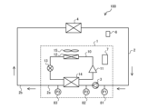
- FIG. 1 is a circuit diagram showing a schematic configuration of a water circulation air conditioning system including a chilling unit according to an embodiment of the present disclosure as a heat source unit.
- FIG. 2 is a block diagram showing the functions of the control device of FIG. 1 .
- FIG. 2 is a diagram showing the relationship between head loss and flow rate of the water heat exchanger of FIG. 1 .
- FIG. 2 is a diagram showing the relationship between the head and flow rate of the pump of FIG. 1.
- 4 is a flowchart showing control during a test run of the chilling unit of FIG. 1 .
- FIG. 1 is a circuit diagram showing a schematic configuration of a water circulation air conditioning system including a chilling unit according to an embodiment of the present disclosure as a heat source unit.
- a water circulation air conditioning system 100 is taken as an example to explain a heat medium circulation system.
- the water circulation air conditioning system 100 includes a chilling unit 1 and a water circuit 2, a part of which is disposed in the chilling unit 1.
- the water circulating through the water circuit 2 corresponds to the heat medium of the present disclosure, and the water circuit 2 corresponds to the heat medium circuit of the present disclosure. Brine may be used as the heat medium.
- the direction in which the water flows is indicated by a solid arrow.
- the chilling unit 1 includes a refrigerant circuit 10, a portion of the water circuit 2, and a control device 7.
- the portion of the water circuit 2 included in the chilling unit 1 is composed of a water piping section 2a and a pump 3 provided in the water piping section 2a.
- the water piping section 2a is the heat medium piping section of the present disclosure.
- the refrigerant circuit 10 of the chilling unit 1 is configured to circulate the refrigerant by piping connections between the compressor 11, the heat source side heat exchanger 12, the throttling device 13, and the water heat exchanger 14.
- the compressor 11 compresses a refrigerant, which is a heat source side refrigerant such as freon.
- the compressor 11 is inverter controlled by the control device 7.
- the heat source side heat exchanger 12 exchanges heat between the refrigerant and air such as outside air.
- a blower fan 15 that blows air to the heat source side heat exchanger 12 is arranged adjacent to the heat source side heat exchanger 12.
- the blower fan 15 is inverter controlled by the control device 7.
- the throttling device 13 adjusts the pressure of the refrigerant.
- the throttling device 13 is controlled to open and close by the control device 7.
- the throttling device 13 can be a valve that can adjust the opening degree, such as a linear expansion valve (LEV).
- LEV linear expansion valve
- the throttling device 13 can also be a capillary tube whose opening degree cannot be adjusted.
- the water heat exchanger 14 exchanges heat with water that is different from the refrigerant.
- the water heat exchanger 14 cools the water in the water circuit 2 to the desired temperature using the heat of the refrigerant.
- the water heat exchanger 14 has a refrigerant flow path through which the refrigerant flows and a water flow path through which water flows, and constitutes the refrigerant circuit 10 and also constitutes the water circuit 2.
- the water heat exchanger 14 is, for example, a plate-type heat exchanger, and is configured such that the refrigerant flow path and the water flow path are alternately overlapped to directly exchange heat.
- the water heat exchanger 14 corresponds to the heat medium heat exchanger of the present disclosure.
- the water flow path corresponds to the heat medium flow path of the present disclosure.
- the refrigerant flowing through the refrigerant circuit 10 may be, for example, a single refrigerant such as R-22 or R-134a, a pseudo-azeotropic mixed refrigerant such as R-410A or R-404A, or a non-azeotropic mixed refrigerant such as R-407C.
- refrigerants that contain a double bond in the chemical formula and have a relatively small global warming potential such as CF 3 CF ⁇ CH 2 or mixtures thereof, or natural refrigerants such as CO 2 or propane may be used.
- the water circuit 2 is configured to circulate water by connecting the chilling unit 1 and the load side heat exchanger 4 with piping. Specifically, the water circuit 2 is configured by connecting the pump 3, the water flow path of the water heat exchanger 14, and the load side heat exchanger 4 with piping. The pump 3 of the chilling unit 1 circulates the water used for heat exchange in the water heat exchanger 14 through the water circuit 2. The pump 3 is inverter controlled by the control device 7.
- the load-side heat exchanger 4 is, for example, a fan coil unit or an air handling unit installed inside the building, and uses water from the water circuit 2 to cool the indoor air.
- the control device 7 is composed of dedicated hardware, or a CPU (Central Processing Unit) that executes programs stored in memory.
- the CPU is also called a central processing unit, processing unit, arithmetic unit, microprocessor, microcomputer, or processor.
- control device 7 When the control device 7 is dedicated hardware, the control device 7 may be, for example, a single circuit, a composite circuit, an ASIC (Application Specific Integrated Circuit), an FPGA (Field-Programmable Gate Array), or a combination of these. Each of the functional units realized by the control device 7 may be realized by separate hardware, or each functional unit may be realized by a single piece of hardware.
- ASIC Application Specific Integrated Circuit
- FPGA Field-Programmable Gate Array
- each function executed by the control device 7 is realized by software, firmware, or a combination of software and firmware.
- Software and firmware are written as programs and stored in memory.
- the CPU realizes each function of the control device 7 by reading and executing the programs stored in the memory.
- the memory is, for example, a non-volatile or volatile semiconductor memory such as a RAM, ROM, flash memory, EPROM, or EEPROM.
- control device 7 Some of the functions of the control device 7 may be realized by dedicated hardware, and some by software or firmware.
- control device 7 is provided inside the chilling unit 1 in the water circulation air conditioning system 100, but this is not limited thereto and the control device 7 may be provided outside the chilling unit 1.
- the water circulation air conditioning system 100 also includes various sensors.
- the chilling unit 1 includes a pre-pump pressure sensor 81 provided on the water suction side of the pump 3 that pumps water to the water heat exchanger 14, an inlet pressure sensor 82 provided between the pump 3 and the water heat exchanger 14, i.e., on the water inlet side of the water heat exchanger 14, and an outlet pressure sensor 83 provided on the water outlet side of the water heat exchanger 14.
- the inlet pressure sensor 82 detects the water pressure at the water inlet of the water heat exchanger 14.
- the outlet pressure sensor 83 detects the water pressure at the water outlet of the water heat exchanger 14.
- the pre-pump pressure sensor 81 detects the water pressure at the water inlet of the pump 3 provided upstream of the water heat exchanger 14.
- the water inlet of the water heat exchanger 14 is the heat medium inlet of the water heat exchanger 14 in this disclosure
- the water outlet of the water heat exchanger 14 is the heat medium outlet of the water heat exchanger 14 in this disclosure
- the water pressure is the heat medium pressure in this disclosure.
- the pressure value detected by the pre-pump pressure sensor 81 is defined as P1, the pressure value detected by the inlet pressure sensor 82 as P2, and the pressure value detected by the outlet pressure sensor 83 as P3. Furthermore, the pressure values P1, P2, and P3 of the pre-pump pressure sensor 81, inlet pressure sensor 82, and outlet pressure sensor 83 are each defined as 0 kPa, with atmospheric pressure being 0 kPa, and values above 0 being positive pressure, and values below 0 being negative pressure.
- the water circulation air conditioning system 100 may be provided with various sensors other than those mentioned above.
- the chilling unit 1 may be provided with an inlet temperature sensor that detects the water temperature at the water inlet of the water heat exchanger 14, and an outlet temperature sensor that detects the water temperature at the water outlet of the water heat exchanger 14.
- the load side heat exchanger 4 may also be provided with an indoor temperature sensor that detects the indoor temperature.
- the control device 7 is connected to various sensors, such as a pre-pump pressure sensor 81, an inlet pressure sensor 82, and an outlet pressure sensor 83, via wireless or wired control signal lines, and the detection values of the various sensors are input to the control device 7.
- the control device 7 is also connected to a remote control 6 via wireless or wired control signal lines.
- the control device 7 is configured to be able to change the operating condition settings in response to the user's operation of the remote control 6, and to display the changed condition settings on the remote control 6.
- the control device 7 is also connected to each actuator, such as the compressor 11, the blower fan 15, the throttling device 13, and the pump 3, via wireless or wired control signal lines, and is able to send operating instructions to each actuator.
- FIG. 2 is a block diagram showing the functions of the control device 7 of FIG. 1.
- the control device 7 has, as functional units, an input unit 71, a calculation unit 72, a control unit 73, and a memory unit 74.
- the input unit 71 is a functional unit to which detection values of various sensors, such as a pre-pump pressure sensor 81, an inlet pressure sensor 82 on the water inlet side of the water heat exchanger 14, and an outlet pressure sensor 83 on the water outlet side of the water heat exchanger 14, are input.
- the input unit 71 receives inputs from the remote control 6 of start and stop of operation, and the user side set temperature during operation.
- the memory unit 74 is a functional unit that stores the setting information input to the input unit 71, various control values used by the control unit 73, and judgment criteria used by the calculation unit 72 to judge various abnormalities. In addition, during a test run immediately after constructing the water circulation air conditioning system 100, the memory unit 74 stores the detection values from the pre-pump pressure sensor 81, the inlet pressure sensor 82, and the outlet pressure sensor 83 input to the input unit 71 in association with the operating frequency of the pump 3 at that time.
- the calculation unit 72 is a functional unit that calculates the control parameters of each actuator based on the information input to the input unit 71 and the information stored in the storage unit 74.
- the calculation unit 72 also performs various abnormality judgments based on the information input to the input unit 71 and the information stored in the storage unit 74, and outputs necessary information based on the results of these abnormality judgments to the notification unit 99, which will be described later. Details of the various abnormality judgments will be described later.
- the calculation unit 72 determines and detects abnormalities around the water heat exchanger 14 and abnormalities around the pump 3 based on the pressure values P1, P2, and P3 detected by the pre-pump pressure sensor 81, the inlet pressure sensor 82, and the outlet pressure sensor 83, and the pressure values (pressure values P21, P22, P23, P31, P32, and P33 described below) previously stored in the memory unit 74.
- the pressure values P21, P22, P23, P31, P32, and P33 used in abnormality determination will be described later.
- the control unit 73 is a functional unit that controls each actuator, such as the compressor 11, the blower fan 15, the throttling device 13, and the pump 3, based on the control parameters calculated by the calculation unit 72. Specifically, the control unit 73 controls the frequency of the compressor 11, the rotation speed of the blower fan 15, the opening degree of the throttling device 13, and the frequency of the pump 3, etc.
- the chilling unit 1 also includes a notification unit 99 that notifies the user of abnormality information when an abnormality is detected by the calculation unit 72.
- the abnormality information is, for example, the result of the abnormality determination indicating the cause when the flow rate calculated from the pressure difference (P2-P3) before and after the water heat exchanger 14 is outside the range of the flow rate during operation, or treatment information indicating the treatment to be performed for the result of the abnormality determination.
- the notification unit 99 may also be configured to notify the user of abnormality information such as the result of the abnormality determination and treatment information when a certain condition is satisfied, even if the flow rate calculated from the pressure difference (P2-P3) before and after the water heat exchanger 14 is within the range of the flow rate during operation.
- the notification unit 99 is configured, for example, as a liquid crystal display or a speaker, and notifies the user of the abnormality information by text, sound, light, or the like.
- a worker performing regular inspection can know the abnormality of the water flow around the water heat exchanger 14 and the pump 3 and the location of the cause of the abnormality by checking the abnormality information displayed on the notification unit 99.
- Fig. 3 is a diagram showing the relationship between head loss [kPa] and flow rate [m 3 /h] of the water heat exchanger 14 in Fig. 1.
- Fig. 4 is a diagram showing the relationship between head [kPa] and flow rate [m 3 /h] of the pump 3 in Fig. 1.
- Fig. 5 is a flowchart showing control during a test run of the chilling unit 1 in Fig. 1. Below, the characteristics of the water heat exchanger 14, the characteristics of the pump 3, and the operation during a test run of the water circulation air conditioning system 100 will be described with reference to Figs. 3 to 5.
- the control device 7 identifies multiple abnormalities that cause changes in the water flow rate in the water heat exchanger 14 and the pump 3 based on the pressure values P1, P2, and P3 detected by the pre-pump pressure sensor 81, the inlet pressure sensor 82, and the outlet pressure sensor 83.
- the horizontal axis indicates the flow rate of water flowing through the water heat exchanger 14, and the vertical axis indicates the head loss of water in the water heat exchanger 14.
- the head loss is the pressure difference (P2-P3) before and after the water heat exchanger 14, and varies depending on, for example, the number of plates constituting the water heat exchanger 14, the length and resistance of the water flow path, etc.
- the horizontal axis indicates the flow rate of water that the pump 3 can deliver, and the vertical axis indicates the head.
- the head is the amount of water pressure increase by the pump 3, and is the pressure difference (P2-P1) before and after the pump 3.
- the rated frequency Fp3 is, for example, the maximum frequency of the pump 3.
- the characteristics of the water heat exchanger 14 shown in FIG. 3 i.e., the head loss diagram
- the characteristics of the pump 3 shown in FIG. 4 i.e., the pump head diagrams such as pump head curves C1 to C3 are stored in advance as initial characteristic data in the memory unit 74, for example, at the time of shipment of the chilling unit 1.
- the characteristics of the pump 3 shown in FIG. 4 do not have to be stored in the memory unit 74 at the time of shipment.
- the operating range of the pump 3 for the specified flow rate range may be automatically set during trial operation using the method described below.
- Step S1 the chilling unit 1 automatically adjusts the operating frequency of the pump 3 to match the upper limit flow rate V2 during operation based on the head loss diagram of the water heat exchanger 14 (see FIG. 3), thereby adjusting the head loss (i.e., P2-P3).
- the range of the flow rate of water flowing through the water heat exchanger 14 is specified, and within the specified flow rate range, the flow rate range is specified according to the site where the chilling unit 1 is installed (specifically, the load of the site, etc.). Therefore, during the trial run, the pump 3 is driven so that the head loss (i.e., P2-P3) obtained from the inlet pressure sensor 82 and the outlet pressure sensor 83 matches the head loss value L2 (see FIG.
- the operating frequency of the pump 3 at this time is stored in the memory unit 74 as the upper limit frequency Fp2 during operation (see FIG. 4).
- Step S2 the chilling unit 1 drives the pump 3 at the upper limit frequency during operation Fp2, and stores the pressure values detected by the pre-pump pressure sensor 81, the inlet pressure sensor 82, and the outlet pressure sensor 83 at this time in correspondence with the upper limit frequency during operation Fp2 in the memory unit 74.
- the pressure values detected by the pre-pump pressure sensor 81, the inlet pressure sensor 82, and the outlet pressure sensor 83 in step S2 of the trial run are referred to as pressure values P11, P12, and P13 to distinguish them from the pressure values P1, P2, and P3 detected by these sensors during operation after the start of operation.
- Step S3 The chilling unit 1 also automatically adjusts the operating frequency of the pump 3 to match the head loss (i.e., P2-P3) to the lower limit flow rate V1 during operation based on the head loss diagram (see FIG. 3) of the water heat exchanger 14.
- the pump 3 is driven so that the head loss obtained from the inlet pressure sensor 82 and the outlet pressure sensor 83 matches the head loss value L1 (see FIG. 3) corresponding to the lower limit of the range of the flow rate of the water heat exchanger 14 specified at the site (i.e., the lower limit flow rate V1 during operation).
- the operating frequency of the pump 3 at this time is stored in the memory unit 74 as the lower limit frequency Fp1 during operation (see FIG. 4).
- Step S4 the chilling unit 1 drives the pump 3 at the lower limit frequency during operation Fp1, and stores the pressure values detected by the pre-pump pressure sensor 81, the inlet pressure sensor 82, and the outlet pressure sensor 83 at this time in correspondence with the lower limit frequency during operation Fp1 in the memory unit 74.
- the pressure values detected by the pre-pump pressure sensor 81, the inlet pressure sensor 82, and the outlet pressure sensor 83 in step S4 of the trial run are referred to as pressure values P21, P22, and P23 to distinguish them from the pressure values P1, P2, and P3 detected by these sensors during operation after the start of operation.
- Step S5 the chilling unit 1 drives the pump 3 at a plurality of frequencies between an operating lower limit frequency Fp1 and an operating upper limit frequency Fp2.
- the chilling unit 1 stores in the memory unit 74 pressure values detected by the pump pre-pressure sensor 81, the inlet pressure sensor 82, and the outlet pressure sensor 83 during operation at each operating frequency in association with the operating frequency of the pump 3.
- the pressure values detected by the pump pre-pressure sensor 81, the inlet pressure sensor 82, and the outlet pressure sensor 83 in step S5 of the trial run are referred to as pressure values P31, P32, and P33 to be distinguished from the pressure values P1, P2, and P3 detected by these sensors during operation after the start of operation.
- the pressure values P31, P32, and P33 each change in value depending on the operating frequency.
- step S1 the operating frequency when the pump 3 is driven so that the flow meter value is the upper operating limit flow rate V2 is set as the upper operating limit frequency Fp2.
- step S3 the operating frequency when the pump 3 is driven so that the flow meter value is the lower operating limit flow rate V1 is set as the lower operating limit frequency Fp1.
- the frequency range of the pump 3 corresponding to the estimated flow rate range can be set from the head loss diagram and the pressure values P2 and P3 detected by the inlet pressure sensor 82 and the outlet pressure sensor 83.
- the pump 3 is driven at multiple frequencies, and pressure values at three points on the suction side of the pump 3, between the pump 3 and the water heat exchanger 14, and on the water outlet side of the water heat exchanger 14 at each frequency are measured and stored in advance.
- the pressure values P21, P22, P23, P31, P32, and P33 are used as judgment criteria for determining and detecting abnormalities around the water heat exchanger 14 and around the pump 3 during operation after the start of operation.
- FIG. 6 is a flow chart showing abnormality determination control of the chilling unit 1 of Fig. 1.
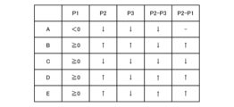
- Fig. 7 is an explanatory diagram showing criteria for each abnormality determination by the control device 7 of Fig. 1. The abnormality determination control performed by the control device 7 during operation after the start of operation will be described with reference to Figs. 6 and 7.
- Step S101) 6 first, it is determined whether the flow rate of water flowing through the water heat exchanger 14 is less than the lower limit flow rate V1 during operation (step S101).
- the flow rate of water flowing through the water heat exchanger 14 is calculated from the pressure difference (P2-P3) between the front and rear of the water heat exchanger 14 obtained from the inlet pressure sensor 82 and the outlet pressure sensor 83, i.e., the head loss, by using the characteristics (see FIG. 3) stored in the memory unit 74.
- step S101 If it is determined in step S101 that the flow rate of water flowing through the water heat exchanger 14 is less than the lower limit flow rate V1 during operation (step S101; YES), the determination in step S102 is performed. On the other hand, if it is determined in step S101 that the flow rate of water flowing through the water heat exchanger 14 is equal to or greater than the lower limit flow rate V1 during operation (step S101; NO), the determination in step S105 is performed.
- Step S102 it is determined whether the pressure value P1 on the suction side of the pump 3 detected by the pump pre-pressure sensor 81 is equal to or greater than 0, i.e., a positive pressure. In step S102, if it is determined that the pressure value P1 is equal to or greater than 0 (step S102; YES), the determination in step S103 is performed. On the other hand, in step S102, if it is determined that the pressure value P1 is less than 0, i.e., a negative pressure (step S102; NO), process A is performed.
- Step S103 it is determined whether the pressure value P3 on the water outlet side of the water heat exchanger 14 detected by the outlet pressure sensor 83 is lower than the pressure value P23 acquired during the test run (see step S4 in FIG. 5).
- the pressure value P23 is the detection value of the outlet pressure sensor 83 when the pump 3 is driven during the test run so that water flows through the water heat exchanger 14 at the operational lower limit flow rate V1, and is stored in the memory unit 74.
- step S103 If it is determined in step S103 that the pressure value P3 is lower than the pressure value P23 during the trial run (step S103; YES), the determination in step S104 is performed. On the other hand, if it is determined in step S103 that the pressure value P3 is equal to or greater than the pressure value P23 during the trial run (step S103; NO), process B is performed.
- Step S104 it is determined whether the pressure value P2 on the inlet side of the water heat exchanger 14 detected by the inlet pressure sensor 82 is higher than the pressure value P22 acquired during the test run (see step S4 in FIG. 5).
- the pressure value P22 is the detection value of the inlet pressure sensor 82 when the pump 3 is driven during the test run so that water flows through the water heat exchanger 14 at the operational lower limit flow rate V1, and is stored in the memory unit 74.
- step S104 If it is determined in step S104 that the pressure value P2 is higher than the pressure value P22 during the trial run (step S104; YES), process D is performed, and if it is determined that the pressure value P2 is equal to or lower than the pressure value P22 during the trial run (step S104; NO), process C is performed.
- Step S105 it is determined whether the pressure value P3 is lower than a predetermined lower limit pressure value (for example, half the pressure value P23 during trial operation). If the pressure value P3 is lower than the lower limit pressure value (step S105; YES), it can be estimated that almost no water flows through the water heat exchanger 14. Therefore, in this case, regardless of the pressure difference (P2-P3) before and after the water heat exchanger 14, it is determined that the water flow is less than the lower limit flow rate V1 during operation, and process D is performed. On the other hand, if it is determined in step S105 that the pressure value P3 is equal to or greater than the lower limit pressure value (step S105; NO), the determination in step S106 is performed.
- a predetermined lower limit pressure value for example, half the pressure value P23 during trial operation.
- Step S106 it is determined whether the flow rate of water flowing through the water heat exchanger 14 is equal to or lower than the upper limit flow rate V2 during operation.
- the flow rate of water flowing through the water heat exchanger 14 is calculated from the pressure difference (P2-P3) between the front and rear of the water heat exchanger 14 obtained from the inlet pressure sensor 82 and the outlet pressure sensor 83, i.e., the head loss, by using the characteristics (see FIG. 3) stored in the memory unit 74.
- step S106 If it is determined in step S106 that the flow rate of the water flowing through the water heat exchanger 14 is equal to or less than the upper limit flow rate V2 during operation (step S106; YES), the determination in step S107 is performed. On the other hand, if it is determined in step S106 that the flow rate of the water flowing through the water heat exchanger 14 exceeds the upper limit flow rate V2 during operation (step S106; NO), the process returns to step S101.
- Step S107 it is determined whether the pressure value P1 on the suction side of the pump 3 detected by the pump pre-pressure sensor 81 is equal to or greater than 0, i.e., a positive pressure. If it is determined in step S107 that the pressure value P1 is equal to or greater than 0 (step S107; YES), the determination in step S108 is performed. On the other hand, if it is determined in step S107 that the pressure value P1 is less than 0, i.e., a negative pressure (step S107; NO), the process returns to step S101.
- Step S108 it is determined whether the pressure value P3 on the water outlet side of the water heat exchanger 14 detected by the outlet pressure sensor 83 is lower than the pressure value P33 acquired during the test operation (see step S5 in FIG. 5).
- the pressure value P33 serving as the criterion for step S108 is the detection value of the outlet pressure sensor 83 acquired during the test operation in which the pump 3 is driven at the same frequency as the current operation frequency, and is stored in the memory unit 74.
- the pressure value P33 acquired by driving the pump 3 at a plurality of operation frequencies during the test operation may be stored in the memory unit 74 as a function of the operation frequency of the pump 3.
- the pressure value P33 serving as the criterion for step S108 is obtained by calculation from the operation frequency of the pump 3 in the current operation.
- step S108 If it is determined in step S108 that the pressure value P3 is lower than the pressure value P33 during the trial run (step S108; YES), the determination in step S109 is performed. On the other hand, if it is determined in step S108 that the pressure value P3 is equal to or greater than the pressure value P33 during the trial run (step S108; NO), the process returns to step S101.
- Step S109 it is determined whether the pressure value P2 on the inlet side of the water heat exchanger 14 detected by the inlet pressure sensor 82 is higher than the pressure value P32 acquired during the test operation (see step S5 in FIG. 5).
- the pressure value P32 serving as the criterion for step S109 is the detection value of the inlet pressure sensor 82 acquired during the test operation in which the pump 3 is driven at the same frequency as the current operation frequency, and is stored in the memory unit 74.
- the pressure value P32 acquired by driving the pump 3 at a plurality of operation frequencies during the test operation may be stored in the memory unit 74 as a function of the operation frequency of the pump 3.
- the pressure value P32 serving as the criterion for step S109 is obtained by calculation from the operation frequency of the pump 3 in the current operation.
- step S109 If it is determined in step S109 that the pressure value P2 is higher than the pressure value P32 during the trial run (step S109; YES), process E is performed. On the other hand, if it is determined in step S109 that the pressure value P2 is equal to or lower than the pressure value P32 during the trial run (step S109; NO), the process returns to step S101.
- Process A in the above-mentioned abnormality determination control, if the flow rate calculated from the head loss (i.e., P2-P3) is less than the lower limit flow rate V1 during operation and the pressure value P1 on the water intake side of the pump 3 is negative, process A is performed. In process A, it is determined that the water flow rate of the water heat exchanger 14 has fallen below the lower limit flow rate V1 during operation due to the negative pressure on the water intake side of the pump 3, and this is output to the notification unit 99 as the result of abnormality determination. In addition to the result of this abnormality determination, information on how to deal with this abnormality, such as "increase the pressure on the water intake side of the pump" or "remove any resistance on the water intake side of the pump", is output to the notification unit 99.
- the pressure value P2 on the water inlet side of the water heat exchanger 14 and the pressure value P3 on the water outlet side of the water heat exchanger 14 are lower than the pressure values P22 and P23 during trial operation when the water flow is set to the lower operational flow rate V1.
- Process D in the above abnormality determination control, if the flow rate calculated from the head loss (i.e., P2-P3) is less than the lower limit flow rate V1 during operation, the pressure value P1 on the water intake side of the pump 3 is positive, the pressure value P3 on the water outlet side of the water heat exchanger 14 is lower than the pressure value P23 during trial operation when the water flow is set to the lower limit flow rate V1 during operation, and the pressure value P2 on the water inlet side of the water heat exchanger 14 is higher than the pressure value P22 during trial operation when the water flow is set to the lower limit flow rate V1 during operation, then process D is performed. In process D, it is determined that the water flow rate of the water heat exchanger 14 has fallen below the lower limit flow rate V1 during operation due to internal freezing of the water heat exchanger 14, and this is output to the notification unit 99 as a result of abnormality determination.
- process E it is determined that dirt such as scale has occurred in the water flow path of the water heat exchanger 14, and this is output to the notification unit 99 as a result of abnormality determination.
- the chilling unit 1 is described as an example in which the water heat exchanger 14 is the evaporator of the refrigerant circuit 10, and the heat of the heat source refrigerant such as freon is used to cool water to a target temperature.
- the chilling unit 1 may be configured to include a four-way valve in the refrigerant circuit 10, and to not only cool water to a target temperature using the heat of the heat source refrigerant such as freon, but also to heat water to a target temperature.
- FIG. 1 shows a configuration in which the refrigerant in the refrigerant flow path and the water in the water flow path flow in countercurrent flow in the water heat exchanger 14, they may also flow in parallel.
- the heat medium flowing through the water circuit 2 has been described as water, it is possible to use not only water but also brine as the heat medium by changing the information on the physical properties of the heat medium. For example, by configuring the control device 7 to calculate the head loss diagram of the water heat exchanger 14 from the type and concentration of the brine, it is possible to operate the system in the same way when using brine as when using water.
- the chilling unit 1 constitutes a part of the heat medium circuit (water circuit 2) and includes a heat medium piping section (water piping section 2a) through which the heat medium flows, a refrigerant circuit 10 having a compressor 11 that compresses the refrigerant and through which the refrigerant circulates by the compressor 11, and a heat medium heat exchanger (water heat exchanger 14) that exchanges heat between the heat medium and the refrigerant.
- a heat medium piping section water piping section 2a
- a refrigerant circuit 10 having a compressor 11 that compresses the refrigerant and through which the refrigerant circulates by the compressor 11, and a heat medium heat exchanger (water heat exchanger 14) that exchanges heat between the heat medium and the refrigerant.
- the heat medium heat exchanger (water heat exchanger 14) has a heat medium flow path through which the heat medium flows and a refrigerant flow path through which the refrigerant flows, is provided in the heat medium piping section (water piping section 2a), and constitutes a part of the heat medium circuit and the refrigerant circuit 10.
- the chilling unit 1 also includes a pump 3 that is provided upstream of the heat medium heat exchanger in the heat medium piping section and sends the heat medium to the heat medium heat exchanger, and a pre-pump pressure sensor 81 that detects the heat medium pressure on the suction side of the pump 3.
- the chilling unit 1 also includes an inlet pressure sensor 82 that detects the heat medium pressure on the heat medium inlet side of the heat medium heat exchanger (water heat exchanger 14) on the discharge side of the pump 3, and an outlet pressure sensor 83 that detects the heat medium pressure on the heat medium outlet side of the heat medium heat exchanger.
- the chilling unit 1 is provided with water pressure sensors on the suction side of the pump and on the heat medium inlet and outlet sides of the heat medium heat exchanger, so that abnormalities around the heat medium heat exchanger and abnormalities around the pump can be detected separately. If the notification unit 99 or the like is configured to notify abnormality information, the worker performing the regular inspection can refer to the notified abnormality information and take action or check the necessary areas, so the area to be treated or checked can be narrower than before, leading to shorter work hours.
- the chilling unit 1 also includes a control device 7 that detects abnormalities in the flow rate of the heat medium flowing through the heat medium heat exchanger (water heat exchanger 14) based on the heat medium pressure (pressure value P1) on the suction side of the pump 3 detected by the pre-pump pressure sensor 81, the heat medium pressure (pressure value P2) on the heat medium inlet side of the heat medium heat exchanger detected by the inlet pressure sensor 82, and the heat medium pressure (pressure value P3) on the heat medium outlet side of the heat medium heat exchanger detected by the outlet pressure sensor 83.
- a control device 7 that detects abnormalities in the flow rate of the heat medium flowing through the heat medium heat exchanger (water heat exchanger 14) based on the heat medium pressure (pressure value P1) on the suction side of the pump 3 detected by the pre-pump pressure sensor 81, the heat medium pressure (pressure value P2) on the heat medium inlet side of the heat medium heat exchanger detected by the inlet pressure sensor 82, and the heat medium pressure (pressure value P3) on the heat medium outlet
- the control device 7 determines that the cause is upstream of pump 3.
- control device 7 stores the heat medium pressure (pressure value P21) on the suction side of the pump 3, the heat medium pressure (pressure value P22) on the heat medium inlet side of the heat medium heat exchanger, and the heat medium pressure (pressure value P23) on the heat medium outlet side of the heat medium heat exchanger when the pump 3 is driven at a predetermined lower limit frequency Fp1 during a trial run before the start of operation.
- the control device 7 calculates the heat medium pressure (pressure value P1) on the suction side of the pump 3 during operation, the heat medium pressure (pressure value P2) on the heat medium inlet side of the heat medium heat exchanger, and the heat medium pressure (pressure value P3) on the heat medium outlet side of the heat medium heat exchanger.
- the heat medium pressure (pressure value P3) at the intake side of the pump 3 when the pump 3 is driven at the lower limit frequency Fp1 during trial operation is compared with the heat medium pressure (pressure value P21) at the heat medium inlet side of the heat medium heat exchanger, and the heat medium pressure (pressure value P23) at the heat medium outlet side of the heat medium heat exchanger.
- the cause of the heat medium flow rate falling below the lower limit flow rate V1 during operation is determined.
- a pre-pump pressure sensor 81 allows the heat transfer medium pressure (pressure values P1, P21) on the suction side of the pump 3 to be detected by the pre-pump pressure sensor 81, and the differential pressure (P2-P1) before and after the pump 3, i.e., the head, to be calculated. Therefore, by increasing the number of parameters that can be used to determine an abnormality, the cause can be distinguished in more detail.
- the control device 7 determines that there is a cause downstream of the heat medium heat exchanger that causes the heat medium flow rate to fall below the lower limit operation flow rate V1 if the heat medium pressure (pressure value P1) on the suction side of the pump 3 is positive and the heat medium pressure (pressure value P3) on the heat medium outlet side of the heat medium heat exchanger is elevated compared to the heat medium pressure (P23) on the heat medium outlet side of the heat medium heat exchanger when the pump is driven at the lower limit operation frequency Fp1 during trial operation.
- the control device 7 determines that the cause of the heat medium flow rate falling below the lower limit operation flow rate is inside the pump 3.
- the control device 7 determines that the heat medium flow rate has fallen below the lower limit operation flow rate V1 due to internal freezing of the heat medium heat exchanger if the heat medium pressure (pressure value P1) on the suction side of the pump 3 is positive and the heat medium pressure (pressure value P2) on the heat medium inlet side of the heat medium heat exchanger is increased compared to the heat medium pressure (pressure value P22) on the heat medium inlet side of the heat medium heat exchanger when the pump is driven at the lower limit operation frequency Fp1 during trial operation.
- the abnormality determination result may be fed back to the control of the compressor 11, etc. For example, when it is determined that the cause of the decrease in the flow rate of the heat medium in the heat medium heat exchanger is internal freezing of the heat medium heat exchanger, it is advisable to adjust the operating frequency of the compressor 11 so that the temperature of the water heat exchanger 14 increases.
- the control device 7 also stores the heat medium pressure (pressure value P31) on the suction side of the pump 3, the heat medium pressure (pressure value P32) on the heat medium inlet side of the heat medium heat exchanger, and the heat medium pressure (pressure value P33) on the heat medium outlet side of the heat medium heat exchanger, for each of the cases in which the pump 3 is driven at a plurality of frequencies during a trial run prior to the start of operation.
- the control device 7 then stores the heat medium pressure (pressure value P1) on the suction side of the pump 3 as a positive pressure and the heat medium pressure (pressure value P2) on the heat medium inlet side of the heat medium heat exchanger as a positive pressure and the heat medium pressure (pressure value P3) on the heat medium outlet side of the heat medium heat exchanger as a positive pressure during operation, when the flow rate of the heat medium calculated from the pressure difference (P2-P3) between the heat medium pressure (pressure value P2) on the heat medium inlet side of the heat medium heat exchanger and the heat medium pressure (pressure value P3) on the heat medium outlet side of the heat medium heat exchanger is within a predetermined flow rate range during operation.
- the chilling unit 1 also includes a notification section 99 that notifies the user of abnormality information when the control device 7 detects an abnormality in the flow rate of the heat medium flowing through the heat medium heat exchanger (water heat exchanger 14). This allows, for example, a worker performing a regular inspection to learn of abnormalities in the water flow around the water heat exchanger 14 and the pump 3 and the abnormality information (for example, the location where the abnormality occurred) by checking the abnormality information notified by the notification section 99.
Landscapes
- Engineering & Computer Science (AREA)
- Mechanical Engineering (AREA)
- General Engineering & Computer Science (AREA)
- Physics & Mathematics (AREA)
- Thermal Sciences (AREA)
- Chemical & Material Sciences (AREA)
- Combustion & Propulsion (AREA)
- Life Sciences & Earth Sciences (AREA)
- Sustainable Development (AREA)
- Other Air-Conditioning Systems (AREA)
- Air Conditioning Control Device (AREA)
Priority Applications (3)
| Application Number | Priority Date | Filing Date | Title |
|---|---|---|---|
| PCT/JP2023/013807 WO2024209508A1 (ja) | 2023-04-03 | 2023-04-03 | チリングユニット |
| JP2025512218A JPWO2024209508A1 (https=) | 2023-04-03 | 2023-04-03 | |
| GB2512752.3A GB2642586A (en) | 2023-04-03 | 2023-04-03 | Chilling unit |
Applications Claiming Priority (1)
| Application Number | Priority Date | Filing Date | Title |
|---|---|---|---|
| PCT/JP2023/013807 WO2024209508A1 (ja) | 2023-04-03 | 2023-04-03 | チリングユニット |
Publications (1)
| Publication Number | Publication Date |
|---|---|
| WO2024209508A1 true WO2024209508A1 (ja) | 2024-10-10 |
Family
ID=92971412
Family Applications (1)
| Application Number | Title | Priority Date | Filing Date |
|---|---|---|---|
| PCT/JP2023/013807 Ceased WO2024209508A1 (ja) | 2023-04-03 | 2023-04-03 | チリングユニット |
Country Status (3)
| Country | Link |
|---|---|
| JP (1) | JPWO2024209508A1 (https=) |
| GB (1) | GB2642586A (https=) |
| WO (1) | WO2024209508A1 (https=) |
Citations (3)
| Publication number | Priority date | Publication date | Assignee | Title |
|---|---|---|---|---|
| JPH05118622A (ja) * | 1991-10-29 | 1993-05-14 | Matsushita Refrig Co Ltd | 冷暖房装置 |
| WO2017221383A1 (ja) * | 2016-06-23 | 2017-12-28 | 三菱電機株式会社 | 熱媒体循環システム |
| WO2021166040A1 (ja) * | 2020-02-17 | 2021-08-26 | 三菱電機株式会社 | 冷凍サイクル装置 |
-
2023
- 2023-04-03 JP JP2025512218A patent/JPWO2024209508A1/ja active Pending
- 2023-04-03 GB GB2512752.3A patent/GB2642586A/en active Pending
- 2023-04-03 WO PCT/JP2023/013807 patent/WO2024209508A1/ja not_active Ceased
Patent Citations (3)
| Publication number | Priority date | Publication date | Assignee | Title |
|---|---|---|---|---|
| JPH05118622A (ja) * | 1991-10-29 | 1993-05-14 | Matsushita Refrig Co Ltd | 冷暖房装置 |
| WO2017221383A1 (ja) * | 2016-06-23 | 2017-12-28 | 三菱電機株式会社 | 熱媒体循環システム |
| WO2021166040A1 (ja) * | 2020-02-17 | 2021-08-26 | 三菱電機株式会社 | 冷凍サイクル装置 |
Also Published As
| Publication number | Publication date |
|---|---|
| JPWO2024209508A1 (https=) | 2024-10-10 |
| GB2642586A (en) | 2026-01-14 |
Similar Documents
| Publication | Publication Date | Title |
|---|---|---|
| CN107407514B (zh) | 空调室内机 | |
| JP5289109B2 (ja) | 空気調和装置 | |
| US10168067B2 (en) | Detecting and handling a blocked condition in the coil | |
| JP6341808B2 (ja) | 冷凍空調装置 | |
| CN112074691B (zh) | 空调管理系统、空调管理方法及程序 | |
| CN109556232A (zh) | 四通阀异常检测方法、装置及空调机组 | |
| JPWO2020070892A1 (ja) | 空気調和機、空気調和機の制御方法およびプログラム | |
| CN103842736B (zh) | 制冷装置 | |
| JP6444577B1 (ja) | 空気調和機 | |
| CA3093930C (en) | Avoiding coil freeze in hvac systems | |
| CN108870633A (zh) | 空调系统的控制方法和装置 | |
| JP7367216B2 (ja) | 冷凍サイクル装置 | |
| JP4869117B2 (ja) | 空気調和装置 | |
| JP4341615B2 (ja) | 空気調和装置 | |
| JP6661775B2 (ja) | 空気調和装置 | |
| WO2022194218A1 (zh) | 一拖多空调器的压缩机频率的控制方法及一拖多空调器 | |
| JP2002147905A (ja) | 冷凍装置 | |
| GB2548526A (en) | Indoor unit and air conditioning device using same | |
| WO2007007576A1 (ja) | 空気調和装置 | |
| WO2024209508A1 (ja) | チリングユニット | |
| US11585578B2 (en) | Refrigeration cycle apparatus | |
| EP3974737B1 (en) | Air conditioner device and heat medium flow rate calculation method | |
| JP6042024B2 (ja) | 空気調和装置 | |
| EP3309470A1 (en) | Air conditioning device | |
| JP6971400B2 (ja) | 空調システム、空調方法、及びプログラム |
Legal Events
| Date | Code | Title | Description |
|---|---|---|---|
| 121 | Ep: the epo has been informed by wipo that ep was designated in this application |
Ref document number: 23931923 Country of ref document: EP Kind code of ref document: A1 |
|
| WWE | Wipo information: entry into national phase |
Ref document number: 2025512218 Country of ref document: JP |
|
| ENP | Entry into the national phase |
Ref document number: 202512752 Country of ref document: GB Kind code of ref document: A Free format text: PCT FILING DATE = 20230403 |
|
| WWE | Wipo information: entry into national phase |
Ref document number: 2512752.3 Country of ref document: GB |
|
| NENP | Non-entry into the national phase |
Ref country code: DE |
|
| WWP | Wipo information: published in national office |
Ref document number: 2512752.3 Country of ref document: GB |
|
| 122 | Ep: pct application non-entry in european phase |
Ref document number: 23931923 Country of ref document: EP Kind code of ref document: A1 |