WO2024204486A1 - 蓄電装置 - Google Patents
蓄電装置 Download PDFInfo
- Publication number
- WO2024204486A1 WO2024204486A1 PCT/JP2024/012543 JP2024012543W WO2024204486A1 WO 2024204486 A1 WO2024204486 A1 WO 2024204486A1 JP 2024012543 W JP2024012543 W JP 2024012543W WO 2024204486 A1 WO2024204486 A1 WO 2024204486A1
- Authority
- WO
- WIPO (PCT)
- Prior art keywords
- energy storage
- storage element
- spacer
- insulating
- insulating member
- Prior art date
- Legal status (The legal status is an assumption and is not a legal conclusion. Google has not performed a legal analysis and makes no representation as to the accuracy of the status listed.)
- Ceased
Links
Images






Classifications
-
- H—ELECTRICITY
- H01—ELECTRIC ELEMENTS
- H01G—CAPACITORS; CAPACITORS, RECTIFIERS, DETECTORS, SWITCHING DEVICES, LIGHT-SENSITIVE OR TEMPERATURE-SENSITIVE DEVICES OF THE ELECTROLYTIC TYPE
- H01G11/00—Hybrid capacitors, i.e. capacitors having different positive and negative electrodes; Electric double-layer [EDL] capacitors; Processes for the manufacture thereof or of parts thereof
- H01G11/14—Arrangements or processes for adjusting or protecting hybrid or EDL capacitors
- H01G11/18—Arrangements or processes for adjusting or protecting hybrid or EDL capacitors against thermal overloads, e.g. heating, cooling or ventilating
-
- H—ELECTRICITY
- H01—ELECTRIC ELEMENTS
- H01G—CAPACITORS; CAPACITORS, RECTIFIERS, DETECTORS, SWITCHING DEVICES, LIGHT-SENSITIVE OR TEMPERATURE-SENSITIVE DEVICES OF THE ELECTROLYTIC TYPE
- H01G11/00—Hybrid capacitors, i.e. capacitors having different positive and negative electrodes; Electric double-layer [EDL] capacitors; Processes for the manufacture thereof or of parts thereof
- H01G11/78—Cases; Housings; Encapsulations; Mountings
- H01G11/82—Fixing or assembling a capacitive element in a housing, e.g. mounting electrodes, current collectors or terminals in containers or encapsulations
-
- H—ELECTRICITY
- H01—ELECTRIC ELEMENTS
- H01M—PROCESSES OR MEANS, e.g. BATTERIES, FOR THE DIRECT CONVERSION OF CHEMICAL ENERGY INTO ELECTRICAL ENERGY
- H01M10/00—Secondary cells; Manufacture thereof
- H01M10/60—Heating or cooling; Temperature control
- H01M10/61—Types of temperature control
- H01M10/613—Cooling or keeping cold
-
- H—ELECTRICITY
- H01—ELECTRIC ELEMENTS
- H01M—PROCESSES OR MEANS, e.g. BATTERIES, FOR THE DIRECT CONVERSION OF CHEMICAL ENERGY INTO ELECTRICAL ENERGY
- H01M10/00—Secondary cells; Manufacture thereof
- H01M10/60—Heating or cooling; Temperature control
- H01M10/64—Heating or cooling; Temperature control characterised by the shape of the cells
- H01M10/647—Prismatic or flat cells, e.g. pouch cells
-
- H—ELECTRICITY
- H01—ELECTRIC ELEMENTS
- H01M—PROCESSES OR MEANS, e.g. BATTERIES, FOR THE DIRECT CONVERSION OF CHEMICAL ENERGY INTO ELECTRICAL ENERGY
- H01M10/00—Secondary cells; Manufacture thereof
- H01M10/60—Heating or cooling; Temperature control
- H01M10/65—Means for temperature control structurally associated with the cells
- H01M10/657—Means for temperature control structurally associated with the cells by electric or electromagnetic means
- H01M10/6572—Peltier elements or thermoelectric devices
-
- H—ELECTRICITY
- H01—ELECTRIC ELEMENTS
- H01M—PROCESSES OR MEANS, e.g. BATTERIES, FOR THE DIRECT CONVERSION OF CHEMICAL ENERGY INTO ELECTRICAL ENERGY
- H01M10/00—Secondary cells; Manufacture thereof
- H01M10/60—Heating or cooling; Temperature control
- H01M10/65—Means for temperature control structurally associated with the cells
- H01M10/658—Means for temperature control structurally associated with the cells by thermal insulation or shielding
-
- H—ELECTRICITY
- H01—ELECTRIC ELEMENTS
- H01M—PROCESSES OR MEANS, e.g. BATTERIES, FOR THE DIRECT CONVERSION OF CHEMICAL ENERGY INTO ELECTRICAL ENERGY
- H01M50/00—Constructional details or processes of manufacture of the non-active parts of electrochemical cells other than fuel cells, e.g. hybrid cells
- H01M50/20—Mountings; Secondary casings or frames; Racks, modules or packs; Suspension devices; Shock absorbers; Transport or carrying devices; Holders
- H01M50/202—Casings or frames around the primary casing of a single cell or a single battery
-
- H—ELECTRICITY
- H01—ELECTRIC ELEMENTS
- H01M—PROCESSES OR MEANS, e.g. BATTERIES, FOR THE DIRECT CONVERSION OF CHEMICAL ENERGY INTO ELECTRICAL ENERGY
- H01M50/00—Constructional details or processes of manufacture of the non-active parts of electrochemical cells other than fuel cells, e.g. hybrid cells
- H01M50/20—Mountings; Secondary casings or frames; Racks, modules or packs; Suspension devices; Shock absorbers; Transport or carrying devices; Holders
- H01M50/204—Racks, modules or packs for multiple batteries or multiple cells
- H01M50/207—Racks, modules or packs for multiple batteries or multiple cells characterised by their shape
- H01M50/209—Racks, modules or packs for multiple batteries or multiple cells characterised by their shape adapted for prismatic or rectangular cells
-
- H—ELECTRICITY
- H01—ELECTRIC ELEMENTS
- H01M—PROCESSES OR MEANS, e.g. BATTERIES, FOR THE DIRECT CONVERSION OF CHEMICAL ENERGY INTO ELECTRICAL ENERGY
- H01M50/00—Constructional details or processes of manufacture of the non-active parts of electrochemical cells other than fuel cells, e.g. hybrid cells
- H01M50/20—Mountings; Secondary casings or frames; Racks, modules or packs; Suspension devices; Shock absorbers; Transport or carrying devices; Holders
- H01M50/289—Mountings; Secondary casings or frames; Racks, modules or packs; Suspension devices; Shock absorbers; Transport or carrying devices; Holders characterised by spacing elements or positioning means within frames, racks or packs
-
- H—ELECTRICITY
- H01—ELECTRIC ELEMENTS
- H01M—PROCESSES OR MEANS, e.g. BATTERIES, FOR THE DIRECT CONVERSION OF CHEMICAL ENERGY INTO ELECTRICAL ENERGY
- H01M50/00—Constructional details or processes of manufacture of the non-active parts of electrochemical cells other than fuel cells, e.g. hybrid cells
- H01M50/20—Mountings; Secondary casings or frames; Racks, modules or packs; Suspension devices; Shock absorbers; Transport or carrying devices; Holders
- H01M50/289—Mountings; Secondary casings or frames; Racks, modules or packs; Suspension devices; Shock absorbers; Transport or carrying devices; Holders characterised by spacing elements or positioning means within frames, racks or packs
- H01M50/291—Mountings; Secondary casings or frames; Racks, modules or packs; Suspension devices; Shock absorbers; Transport or carrying devices; Holders characterised by spacing elements or positioning means within frames, racks or packs characterised by their shape
-
- H—ELECTRICITY
- H01—ELECTRIC ELEMENTS
- H01M—PROCESSES OR MEANS, e.g. BATTERIES, FOR THE DIRECT CONVERSION OF CHEMICAL ENERGY INTO ELECTRICAL ENERGY
- H01M50/00—Constructional details or processes of manufacture of the non-active parts of electrochemical cells other than fuel cells, e.g. hybrid cells
- H01M50/20—Mountings; Secondary casings or frames; Racks, modules or packs; Suspension devices; Shock absorbers; Transport or carrying devices; Holders
- H01M50/289—Mountings; Secondary casings or frames; Racks, modules or packs; Suspension devices; Shock absorbers; Transport or carrying devices; Holders characterised by spacing elements or positioning means within frames, racks or packs
- H01M50/293—Mountings; Secondary casings or frames; Racks, modules or packs; Suspension devices; Shock absorbers; Transport or carrying devices; Holders characterised by spacing elements or positioning means within frames, racks or packs characterised by the material
-
- Y—GENERAL TAGGING OF NEW TECHNOLOGICAL DEVELOPMENTS; GENERAL TAGGING OF CROSS-SECTIONAL TECHNOLOGIES SPANNING OVER SEVERAL SECTIONS OF THE IPC; TECHNICAL SUBJECTS COVERED BY FORMER USPC CROSS-REFERENCE ART COLLECTIONS [XRACs] AND DIGESTS
- Y02—TECHNOLOGIES OR APPLICATIONS FOR MITIGATION OR ADAPTATION AGAINST CLIMATE CHANGE
- Y02E—REDUCTION OF GREENHOUSE GAS [GHG] EMISSIONS, RELATED TO ENERGY GENERATION, TRANSMISSION OR DISTRIBUTION
- Y02E60/00—Enabling technologies; Technologies with a potential or indirect contribution to GHG emissions mitigation
- Y02E60/10—Energy storage using batteries
Definitions
- the present invention relates to an electricity storage device.
- Patent Document 1 discloses a battery pack consisting of multiple batteries arranged with an insulating separator sandwiched between them.
- the separator is a resin molded product manufactured by, for example, resin molding.
- the separator has a cooling air passage through which cooling air passes between the separator and the batteries, a holding part that holds the batteries so as to surround all corners of the batteries, and an insulating part that is interposed between adjacent batteries.
- the separator has a cooling air passage between the insulating part of the separator and the adjacent battery. This causes the size of the battery pack to increase in the direction in which the separator and the batteries are arranged. It is therefore possible to cool the battery from a side of the battery that is not adjacent to the insulating part of the separator.
- the above conventional separator has a holding part that holds the battery so as to surround all corners of the battery. Therefore, it is not easy to cool the battery from that side.
- the present invention was made by the inventors of the present application by focusing on the above problem, and aims to provide an electricity storage device that can efficiently control the temperature of the storage elements.
- the energy storage device comprises an energy storage element, a spacer arranged along the energy storage element, and an insulating member, the spacer comprises a spacer body portion facing the energy storage element in a first direction, the energy storage element comprises a first side surface on one side in a second direction perpendicular to the first direction, the insulating member is bonded to the first side surface, and the spacer body portion does not protrude beyond the insulating member to one side in the second direction.
- the present invention provides an energy storage device that can efficiently control the temperature of the energy storage element.
- FIG. 1 is a perspective view showing the appearance of a power storage device according to an embodiment.
- FIG. 2 is an exploded perspective view of the electricity storage device according to the embodiment.
- FIG. 3 is a perspective view of an energy storage element according to an embodiment.
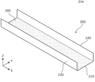
- FIG. 4 is a perspective view showing the appearance of the insulating member according to the embodiment.
- FIG. 5 is a perspective view of a spacer according to the embodiment.
- FIG. 6 is a front view of the spacer according to the embodiment.
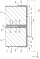
- FIG. 7 is a cross-sectional view showing a spacer and an insulating member according to the embodiment.
- FIG. 8A is a side view showing the structural relationship between a substrate and an energy storage element according to an embodiment.
- FIG. 8B is a side view showing a state in which the base material according to the embodiment is being folded.
- FIG. 8C is a side view showing a state in which the folding of the base material according to the embodiment is completed.
- An energy storage device comprises an energy storage element, a spacer arranged along the energy storage element, and an insulating member, the spacer comprises a spacer body portion facing the energy storage element in a first direction, the energy storage element comprises a first side surface on one side in a second direction perpendicular to the first direction, the insulating member is bonded to the first side surface, and the spacer body portion does not protrude beyond the insulating member to one side in the second direction.
- the spacer main body does not protrude from the insulating member bonded to the first side of the energy storage element. Therefore, the first side of the energy storage element can be brought into contact with a temperature control member for controlling the temperature of the energy storage element via the insulating member. Therefore, the temperature of the energy storage element can be efficiently controlled.
- the width of the insulating member in a third direction perpendicular to the first direction and the second direction may be shorter than the width of the first side surface.
- the width of the insulating member in the third direction is shorter than the width of the first side surface in the third direction, so that the insulating member is prevented from protruding from the first side surface in the third direction, thereby preventing the insulating member from peeling off (turning up) from the first side surface.
- the spacer may further include an opposing wall portion that faces an end portion of the first side surface in a third direction perpendicular to the first direction and the second direction, and the end portion of the insulating member in the third direction may be located between the opposing wall portion and the first side surface.
- the opposing wall portion of the spacer can restrict movement of the energy storage element to one side in the second direction. Since the opposing wall portion overlaps the end portion of the insulating member in the third direction, the area of the first side surface of the energy storage element that is not covered by the insulating member is covered by the opposing wall portion, thereby more reliably insulating it from other members.
- the first side may be a bottom surface of the energy storage element.
- the energy storage element is placed on the temperature control member, so that the weight of the energy storage element can be used to improve adhesion between the temperature control member and the insulating member bonded to the bottom surface of the energy storage element.
- the insulating member may include a first insulating portion bonded to the first side surface and a second insulating portion connected to the first insulating portion, the energy storage element may include a second side surface facing the spacer main body portion in the first direction, and the second insulating portion may be located between the spacer main body portion and the second side surface.
- the second insulating portion of the insulating member is disposed between the spacer and the second side of the energy storage element, so that the creepage distance between the other member on the opposite side of the spacer from the energy storage element and the first side increases. This makes it possible to suppress defects caused by electrical conduction between the energy storage element and the other member.
- the spacer may have a protrusion that protrudes toward the energy storage element, and the protrusion may contact the energy storage element in the protruding direction of the protrusion, but may not contact the insulating member in the protruding direction.
- the convex portion of the spacer comes into contact with the energy storage element, compressing the convex portion in the protruding direction. This makes it possible to limit the movement of the energy storage element while absorbing the size tolerance of the energy storage element. Since no insulating member is sandwiched between the convex portion and the energy storage element, the size of the energy storage device is unlikely to increase due to the placement of the insulating member.
- the convex portion may protrude from the spacer body toward the energy storage element.
- the convex portion of the spacer can limit the movement of the energy storage element while absorbing the size tolerance of the energy storage element in the first direction, which is the alignment direction of the energy storage element and the spacer.
- the insulating member is not sandwiched between the convex portion and the energy storage element in the first direction. Therefore, it is possible to suppress an increase in the size of the energy storage device in the first direction due to the arrangement of the insulating member.
- the X-axis direction is defined as the arrangement direction of a pair of terminals in one storage element, the opposing direction of a pair of short side surfaces in one storage element, or the arrangement direction of a pair of side members.
- the Y-axis direction is defined as the arrangement direction of multiple storage elements, the arrangement direction of multiple spacers, the arrangement direction of a pair of end members, the opposing direction of a pair of long side surfaces in one storage element, or the thickness direction of the storage element or end member.
- the Z-axis direction is defined as the arrangement direction of the container body and the cover plate in the container of the storage element, the vertical direction, or the arrangement direction of the container body and the temperature control member.
- the X-axis direction, Y-axis direction, and Z-axis direction intersect with each other (in this embodiment, the X-axis direction, Y-axis direction, and Z-axis direction are mutually perpendicular).
- the Z-axis direction is not the vertical direction, but for convenience of explanation, the following description will be given assuming that the Z-axis direction is the vertical direction.
- the positive X-axis direction refers to the direction of the arrow on the X-axis
- the negative X-axis direction refers to the opposite direction to the positive X-axis direction.
- the X-axis direction it refers to both or either of the positive X-axis direction and the negative X-axis direction.
- the Y-axis direction and the Z-axis direction may be referred to as the first direction
- the Z-axis direction may be referred to as the second direction
- the X-axis direction may be referred to as the third direction.
- Expressions indicating relative directions or attitudes may also include cases where the directions or attitudes are not strictly the same.
- Two directions being parallel not only means that the two directions are completely parallel, but also means that the directions are substantially parallel, that is, that there is a difference of about several percent.
- the term "insulation” when used, it means “electrical insulation”. It is preferable that the insulating material is formed from a material having a volume resistivity of 1 ⁇ 10 10 ⁇ m or more.
- FIG. 1 is a perspective view showing the external appearance of the power storage device 10 according to the embodiment.
- Fig. 2 is an exploded perspective view of the power storage device 10 according to the embodiment.
- the power storage device 10 is a device that can charge electricity from an external source and discharge electricity to the outside.
- the power storage device 10 is a battery module (battery pack) used for power storage or power supply.
- the power storage device 10 is used as a battery for driving or starting the engine of a moving object such as an automobile, motorcycle, watercraft, ship, snowmobile, agricultural machinery, construction machinery, automatic guided vehicle (AGV), or electric railway vehicle.
- a moving object such as an automobile, motorcycle, watercraft, ship, snowmobile, agricultural machinery, construction machinery, automatic guided vehicle (AGV), or electric railway vehicle.
- Examples of the above automobiles include electric vehicles (EVs), hybrid electric vehicles (HEVs), plug-in hybrid electric vehicles (PHEVs), and fossil fuel (gasoline, diesel, liquefied natural gas, etc.) vehicles.
- Examples of the above electric railway vehicles include electric trains, monorails, linear motor cars, and hybrid electric trains equipped with both a diesel engine and an electric motor.
- the power storage device 10 may be used as a stationary battery
- the energy storage device 10 includes a storage element array 30 formed by arranging a plurality of storage elements 20, and a restraining member 600 having a pair of end members 400 and a pair of side members 500.
- the storage element array 30 includes spacers 100 arranged at both ends of the arrangement direction of the plurality of storage elements 20 (Y-axis direction in this embodiment), and a spacer 150 arranged between two adjacent storage elements 20.
- the opposing direction between the storage element 20 and the main body portion (spacer main body portion 151, see FIG. 5 described later) of the spacer 150 adjacent to the storage element 20 is an example of the first direction.
- the first direction coincides with the arrangement direction (arrangement direction) of the plurality of storage elements 20 and the Y-axis direction.
- the energy storage device 10 includes a side sheet 580 disposed between the side member 500 and the energy storage element array 30.
- the energy storage device 10 also includes bus bars that connect the energy storage elements 20 in series or parallel, but illustration and description of these are omitted.
- the energy storage device 10 may also include a bus bar frame that positions the bus bars, an exterior body that houses the above components, external terminals that connect to external bus bars, and electrical equipment such as circuit boards, fuses, relays, and connectors that monitor or control the charging and discharging states of the energy storage elements 20.
- the energy storage element 20 is a secondary battery (single cell), and more specifically, a non-aqueous electrolyte secondary battery such as a lithium ion secondary battery.
- the energy storage element 20 has a flat rectangular parallelepiped shape (square). In this embodiment, eight energy storage elements 20 are arranged in the Y-axis direction. The size, shape, and number of the energy storage elements 20 arranged are not limited, and the number of the energy storage elements 20 may be one or more.
- the energy storage element 20 may be a secondary battery other than a non-aqueous electrolyte secondary battery, or may be a capacitor.
- the energy storage element 20 may be a primary battery.
- the energy storage element 20 may be a battery using a solid electrolyte.
- the insulating member 200 is fixed to the multiple energy storage elements 20 by adhesive.
- the insulating member 200 is a resin sheet.
- the multiple energy storage elements 20 are in contact with a temperature control member (not shown in Figures 1 and 2) via the insulating member 200, which prevents the energy storage elements 20 from becoming too hot.
- a temperature control member not shown in Figures 1 and 2
- the detailed configurations of the energy storage elements 20 and the insulating member 200 in this embodiment will be described later using Figures 3 to 8C.
- Spacers 100 and 150 are plate-shaped members that are disposed adjacent to the energy storage elements 20 and insulate the energy storage elements 20 from other members.
- Spacer 150 is an inter-cell spacer that is disposed between two energy storage elements 20 adjacent in the Y-axis direction and insulates one of the two energy storage elements 20 from the other.
- Spacer 100 is an end spacer that is disposed between an end element 20 at the end of the energy storage element array 30 and an end member 400 and insulates the energy storage element 20 from the end member 400.
- spacers 100 and 150 also function as cell holders that hold the energy storage elements 20.
- spacers 150 and a pair (two) of spacers 100 are arranged for eight energy storage elements 20.
- the number of spacers 100 and 150 may be changed as appropriate depending on the number of energy storage elements 20 included in the energy storage device 10.
- the spacers 100 and 150 are formed of insulating materials such as polycarbonate (PC), polypropylene (PP), polyethylene (PE), polystyrene (PS), polyphenylene sulfide resin (PPS), polyphenylene ether (PPE (including modified PPE)), polyethylene terephthalate (PET), polybutylene terephthalate (PBT), polyether ether ketone (PEEK), tetrafluoroethylene perfluoroalkyl vinyl ether (PFA), polytetrafluoroethylene (PTFE), polyether sulfone (PES), polyamide (PA), ABS resin, or composite materials thereof, metals with insulating coating, or heat-insulating materials such as an aggregate of mica pieces.
- PC polycarbonate
- PP polypropylene
- PE polyethylene
- PS polystyrene
- PPS polyphenylene sulfide resin
- PPE polyphenylene ether
- PPE polyphenylene ether
- the restraining member 600 is a member that compresses (restrains) the energy storage element array 30 in the arrangement direction (Y-axis direction) by the end member 400 and the side member 500.
- the end member 400 and the side member 500 are formed of metal members such as steel or stainless steel from the viewpoint of ensuring strength, but the material is not particularly limited.
- the end member 400 and the side member 500 may be formed of a high-strength insulating member, or the metal member may be subjected to an insulating treatment.
- the end members 400 are disposed on both sides of the energy storage element array 30 in the Y-axis direction, and are members that sandwich and hold the energy storage element array 30 from both sides in the arrangement direction (Y-axis direction).
- the end members 400 are block-shaped members.
- a plate-shaped member e.g., called an "end plate” with its thickness direction oriented in the Y-axis direction may also be used as the end members 400.
- the side member 500 is a plate-like, elongated member arranged on the side of the energy storage element array 30 in the X-axis direction perpendicular to the Y-axis direction, which is the arrangement direction (first direction).
- the side members 500 are arranged on both the positive and negative X-axis directions of the energy storage element array 30.
- Side sheets 580 are arranged between the pair of side members 500 and the energy storage element array 30. Both ends of the side member 500 in the Y-axis direction are attached to the pair of end members 400, and by connecting the pair of end members 400, the energy storage element array 30 is restrained.
- the side member 500 is connected to the end member 400 by two bolts 750 aligned in the Z-axis direction.
- the connection of the side member 500 to the end member 400 is not limited to fixing with the bolts 750, and may be connected by welding, crimping, or the like.
- the side member 500 is, for example, a plate-shaped member called a "side plate," but there is no particular limitation on the shape of the side member 500.
- a round bar-shaped or square bar-shaped member may be adopted as the side member 500.
- the number of connection points between one side member 500 and one end member 400 does not have to be two, and may be one or three or more.
- One side member 500 and one end member 400 may be connected by three or more bolts 750.
- the side sheets 580 are plate-shaped, elongated insulating members (insulators) that are arranged on both sides of the energy storage element array 30 in the X-axis direction and extend in the Y-axis direction.
- the side sheets 580 insulate the multiple energy storage elements 20 from the side members 500.
- the side sheets 580 may be made of any material that has insulating properties, and can be made of, for example, any insulating material that can be used for the spacers 100 and 150 and the insulating members 200.
- Fig. 3 is a perspective view of an energy storage element 20 according to an embodiment.
- the energy storage element 20 includes a container 21 and a pair of terminals 22 (positive and negative electrodes).
- An electrode body, a pair of current collectors (positive and negative electrodes), an electrolyte (non-aqueous electrolyte), and the like are contained inside the container 21, but are not shown.
- electrolyte non-aqueous electrolyte
- the energy storage element 20 may have spacers, etc., arranged to the side or below the electrode body.
- the container 21 is a rectangular parallelepiped (box-shaped) case.
- the container 21 has a container body 24 and a cover plate 25 that closes the opening of the container body 24. After the electrode body, etc. are housed inside the container body 24, the container body 24 and the cover plate 25 are joined by welding or the like to seal the inside of the container 21.
- the materials of the container body 24 and the cover plate 25 are not particularly limited, but are preferably weldable metals such as stainless steel, aluminum, aluminum alloy, iron, and plated steel sheet.
- the container 21 has a first side 21a in the negative Z direction, a second side 21b in the positive and negative Y directions, a third side 21c in the positive and negative X directions, and a fourth side 21d in the positive Z direction.
- the Z direction is an example of the second direction
- the negative Z direction is an example of one side of the second direction.
- the X direction is an example of the third direction.
- the first side surface 21a is the bottom surface of the container 21, a portion of which is covered by the insulating member 200, and another portion of which is exposed from the insulating member 200.
- the first side surface 21a has an exposed portion 21e that is not covered by the insulating member 200.
- the second side surface 21b is the long side surface of the container 21, the third side surface 21c is the short side surface of the container 21, and the fourth side surface 21d is the terminal arrangement surface of the container 21.
- the first side surface 21a, the second side surface 21b, and the third side surface 21c are formed by the container body 24, and the fourth side surface 21d is formed by the cover plate 25.
- the bottom surface of the container 21 can be described as the surface facing downward when the energy storage element 20 is in use, or the surface facing the opposite direction (negative Z-axis direction) to the direction in which the terminal 22 of the energy storage element 20 is arranged (positive Z-axis direction).
- the terminal 22 is arranged on one of a pair of short sides (third side 21c in this embodiment) rather than on the fourth side 21d.
- the other of the pair of third side surfaces 21c is the bottom surface.
- the bottom surface of the energy storage element 20 is the outer surface of the wall portion of the container body 24 that faces the cover plate 25 (the surface that contacts the space or object outside the container 21).
- the second side surface 21b which is the long side surface, is arranged opposite the adjacent spacer 100 or 150 in the Y-axis direction.
- the third side surface 21c which is the short side surface, is adjacent to the first side surface 21a, the second side surface 21b, and the fourth side surface 21d, and has a smaller area than the second side surface 21b.
- a pair of terminals 22 are arranged on the fourth side surface 21d.
- a gas exhaust valve or the like may be arranged on the fourth side surface 21d to release pressure inside the container 21 if the pressure rises excessively.
- the terminal 22 is electrically connected to the electrode body via the current collector.
- the terminal 22 is made of aluminum, an aluminum alloy, copper, a copper alloy, or the like.
- the terminal 22 has a flat portion to which a conductive member such as a bus bar is welded.
- the terminal 22 may have a shaft portion for fixing a conductive member such as a bus bar using a nut.
- the electrode body is a storage element (power generating element) formed by stacking a positive electrode plate, a negative electrode plate, and a separator.
- the positive electrode plate includes a current collector foil (positive electrode metal foil) and an active material layer formed on the current collector foil.
- the negative electrode plate includes a current collector foil (negative electrode metal foil) and an active material layer formed on the current collector foil.
- the active material used in the active material layer any known material can be used as long as it can absorb and release lithium ions.
- the separator can be a microporous sheet or nonwoven fabric made of resin.
- the electrode body is formed by stacking the electrode plates in the Y-axis direction.
- the electrode body may be of any type, such as a wound type electrode body formed by winding an electrode plate, a stack type electrode body formed by stacking multiple flat electrode plates, or a bellows type electrode body in which the electrode plate is folded in a bellows shape.
- FIG. 4 is a perspective view showing the appearance of the insulating member 200 according to the embodiment.
- the adhesive member 300 is represented by a patterned area.
- the insulating member 200 is a sheet-like member formed of an insulating material such as resin.
- the insulating member 200 is also called an "insulating sheet" or an "insulating film".
- materials for forming the insulating member 200 include insulating resins such as PC, PP, PE, PPS, PET, PBT, or ABS resin, epoxy resin, Kapton (registered trademark), Teflon (registered trademark), silicon, polyisoprene, and polyvinyl chloride.
- the thickness of the insulating member 200 is about 0.1 mm to 1 mm.
- the thermal conductivity of the insulating member is preferably 0.10 W/m ⁇ K or more.
- the insulating member 200 is adhered to the first side surface 21a of the energy storage element 20 in a state where it covers a part of the first side surface 21a.
- the insulating member 200 is adhered to the first side surface 21a by an adhesive member 300 arranged on at least one of the first side surface 21a of the energy storage element 20 and the insulating member 200.
- an adhesive member 300 there is no particular limitation on the type of adhesive member 300, and various adhesives such as resin-based adhesives and silicone-based adhesives, as well as various adhesives such as acrylic-based adhesives and silicone-based adhesives, may be used as the adhesive member 300.
- the insulating member 200 may be adhered to the first side surface 21a by an adhesive layer (adhesive layer) formed on one side of the sheet-like insulating member 200.
- the insulating member 200 includes a first insulating portion 210 bonded to the first side surface 21a, and a second insulating portion 220 connected to the first insulating portion 210. As shown in FIG. 4, the second insulating portion 220 is connected to each of both ends of the first insulating portion 210 in the Y-axis direction. The two second insulating portions 220 face the second side surface 21b (see FIG. 3) of the energy storage element 20.
- the adhesive member 300 is disposed only on the first insulating portion 210, but the adhesive member 300 may also be disposed on the inner surfaces of the two second insulating portions 220 (the mutually opposing surfaces of the two second insulating portions 220). In other words, the second insulating portion 220 may be bonded to the second side surface 21b of the energy storage element 20.
- FIG. 5 is a perspective view of the spacer 150 according to the embodiment.
- FIG. 6 is a view (front view) of the spacer 150 according to the embodiment as viewed from the Y-axis minus direction.
- the outer shape of the container 21 of the energy storage element 20 is represented by a two-dot chain line
- the outer shape of the insulating member 200 is represented by a thick dashed line.
- FIG. 7 is a cross-sectional view showing a cross section of the spacer 150 and the insulating member 200 according to the embodiment. In FIG. 7, a part of the cross section taken along the line VII-VII in FIG. 6 is illustrated, and elements such as the electrode body housed inside the energy storage element 20 are omitted.
- the approximate arrangement range of the temperature control member 800 arranged along the energy storage element string 30 is represented by a two-dot chain line.
- the adhesive member 300 is represented by a dotted line between the energy storage element 20 and the insulating member 200.
- the first insulating portion 210 and the first side surface 21 a are bonded together with an adhesive member 300
- the second insulating portion 220 and the second side surface 21 b are bonded together with an adhesive member 300 .
- the spacer 150 includes a spacer body 151 arranged along the second side surface 21b of the energy storage element 20.
- the spacer body 151 faces the energy storage element 20 in the Y-axis direction.
- the spacer body 151 is positioned between two energy storage elements 20 aligned in the Y-axis direction, thereby suppressing contact between the second side surface 21b located in the positive Y-axis direction of the spacer body 151 and the second side surface 21b located in the negative Y-axis direction of the spacer body 151.
- the spacer 150 includes an opposing wall portion 155, a side wall portion 152, and an upper wall portion 153. As shown in Figures 6 and 7, the opposing wall portion 155 faces the first side surface 21a of the energy storage element 20. The opposing wall portion 155 faces the end portion of the first side surface 21a in the X-axis direction. In this embodiment, the opposing wall portion 155 faces the end portion of the first side surface 21a in the positive direction of the X-axis and the end portion of the first side surface 21a in the negative direction of the X-axis. The opposing wall portion 155 is connected to the edge of the spacer main body portion 151 in the negative direction of the Z-axis, and to both ends in the X-axis direction.
- the edge is exposed between the pair of opposing wall portions 155 at the edge of the spacer main body portion 151 in the negative direction of the Z-axis.
- Each of the pair of opposing wall portions 155 supports the energy storage element 20 from the negative direction of the Z-axis.
- the movement of the energy storage element 20 in the negative Z-axis direction is restricted by a pair of opposing walls 155.
- the pair of opposing wall portions 155 have support portions 156 that protrude in the negative Z-axis direction.
- the spacer 150 has a pair of support portions 156 that are spaced apart in the X-axis direction.
- a pair of support portions 156 are aligned in the Y-axis direction to form two rows of support portions 156.
- the storage element array 30 is supported by the two rows of support portions 156.
- the side wall portions 152 are disposed in the positive and negative directions of the X-axis of the spacer main body portion 151, and face the third side surface 21c (see FIG. 3) of the energy storage element 20. That is, the movement of the energy storage element 20 in the X-axis direction is restricted by the pair of side wall portions 152.
- the upper wall portion 153 is disposed in the positive direction of the Z-axis of the spacer main body portion 151, and faces the fourth side surface 21d (see FIG. 3) of the energy storage element 20. That is, the movement of the energy storage element 20 in the positive direction of the Z-axis is restricted by the upper wall portion 153.
- the energy storage element 20 is surrounded in the X-axis direction, the Y-axis direction, and the Z-axis direction by the spacer 150 arranged along the energy storage element 20.
- the spacer 150 according to this embodiment has a structure for holding the energy storage element 20.
- a pair of opposing wall portions 155 of the spacer 150 are arranged at a distance in the X-axis direction.
- the temperature control member 800 is arranged between the pair of opposing wall portions 155.
- the temperature control member 800 is a member or device that removes heat from (i.e., cools) the multiple energy storage elements 20 by performing heat exchange with the multiple energy storage elements 20 using a liquid or gas flowing inside.
- the temperature control member 800 may be a heat sink that dissipates (radiates) heat absorbed from the energy storage elements 20 to the outside.
- the temperature control member 800 may be a device that electrically cools the energy storage elements 20 using a Peltier element or the like.
- the temperature control member 800 may be a member that provides heat (warms) the multiple energy storage elements 200.
- the temperature control member 800 may be a member that warms the multiple energy storage elements 20 by a liquid or gas flowing inside.
- the temperature control member 800 may be a device that warms the multiple energy storage elements 20 by electrical means.
- the spaces between a pair of opposing wall portions 155 spaced apart in the X-axis direction in the multiple spacers 150 are continuously aligned in the Y-axis direction.
- the edge in the negative Z-axis direction of the spacer main body portion 151 exposed between the pair of opposing wall portions 155 does not protrude from the insulating member 200 adhered to the storage element 20. This makes it easy to bring the temperature control member 800 into contact with the insulating member 200 adhered to the multiple storage elements 20 all at once. In other words, the multiple storage elements 20 can efficiently exchange heat with the temperature control member 800 via the insulating member 200 adhered to the first side surface 21a.
- the energy storage device 10 includes the energy storage element 20, the spacer 150 arranged along the energy storage element 20, and the insulating member 200.
- the spacer 150 includes a spacer main body 151 that faces the energy storage element 20 in the Y-axis direction.
- the energy storage element 20 includes a first side surface 21a on one side in the Z-axis direction (the negative Z-axis direction in this embodiment).
- the insulating member 200 is bonded to the first side surface 21a.
- the spacer main body 151 does not protrude beyond the insulating member 200 in the negative Z-axis direction.
- the spacer body 151 does not protrude from the insulating member 200 bonded to the first side surface 21a of the energy storage element 20. Therefore, as shown in FIG. 7, the first side surface 21a of the energy storage element 20 can be brought into contact with the temperature control member 800 via the insulating member 200. Because the insulating member 200 is bonded to the first side surface 21a, the insulating member 200 and the first side surface 21a are thermally well connected. Therefore, the temperature of the energy storage element 20 is efficiently controlled via the insulating member 200. Because the insulating member 200 is interposed between the temperature control member 800 and the energy storage element 20, the part of the temperature control member 800 facing the energy storage element 20 can be made of metal. The insulating member 200 suppresses conduction between the energy storage element 20 and the temperature control member 800, and heat exchange between the energy storage element 20 and the temperature control member 800 is more efficiently performed.
- a structure is adopted in which the temperature of the storage elements 20 is controlled not in the arrangement direction (Y-axis direction) of the storage elements 20 and the spacer 150, but in a direction perpendicular to the arrangement direction. Therefore, unlike the case where a gas or liquid flow path for controlling the temperature of the storage elements 20 is provided in the spacer main body 151, an increase in the length of the storage element array 30 in the Y-axis direction can be suppressed.
- the adhesive member 300 is disposed between the first side surface 21a and the insulating member 200, it is preferable that the adhesive or pressure-sensitive adhesive used as the adhesive member 300 has a high thermal conductivity. It is preferable that the adhesive or pressure-sensitive adhesive used as the adhesive member 300 has a thermal conductivity of 0.10 W/m ⁇ K or more.
- the position of the edge of the spacer body 151 in the negative Z-axis direction is substantially the same as the position of the surface of the insulating member 200 in the negative Z-axis direction.
- the edge of the spacer body 151 may be located in the positive Z-axis direction from the surface of the insulating member 200.
- the width Wa of the insulating member 200 in the X-axis direction is shorter than the width Wb of the first side surface 21a.
- the first side surface 21a has an exposed portion 21e that is not covered by the insulating member 200. (See Figures 3 and 6).
- the exposed portions 21e are located at both ends of the first side surface 21a in the X-axis direction. In this way, the insulating member 200 is formed to a size that does not cover at least a portion of the first side surface 21a, so that the amount of insulating material such as resin required to form the insulating member 200 can be reduced.
- the spacer 150 has an opposing wall portion 155 that faces the end of the first side surface 21a in the X-axis direction.
- the end of the insulating member 200 in the X-axis direction is located between the opposing wall portion 155 and the first side surface 21a.
- the opposing wall portion 155 can limit the movement of the energy storage element 20 in the negative Z-axis direction.
- the opposing wall portion 155 overlaps the end portion of the insulating member 200 in the X-axis direction. Therefore, the area of the first side surface 21a that is not covered by the insulating member 200 (exposed portion 21e in Figures 3 and 6) is covered by the opposing wall portion 155, thereby providing more reliable insulation from other members.
- the first side surface 21a is the bottom surface of the energy storage element 20. Therefore, as shown in FIG. 7, the energy storage element 20 is placed on the temperature control member 800. Therefore, by utilizing the weight of the energy storage element 20, the adhesion between the temperature control member 800 and the insulating member 200 adhered to the bottom surface of the energy storage element 20 can be improved. This is advantageous from the viewpoint of efficiently controlling the temperature of the energy storage element 20.
- the insulating member 200 includes a first insulating portion 210 bonded to the first side surface 21a, and a second insulating portion 220 connected to the first insulating portion 210.
- the energy storage element 20 includes a second side surface 21b that faces the spacer main body portion 151 in the Y-axis direction. As shown in FIG. 7, the second insulating portion 220 is located between the spacer main body portion 151 and the second side surface 21b.
- the second insulating portion 220 of the insulating member 200 is disposed between the spacer main body 151 and the second side surface 21b of the energy storage element 20. This increases the creepage distance between the other member (such as another energy storage element 20) on the opposite side of the spacer 150 to the energy storage element 20 and the first side surface 21a of the energy storage element 20. This makes it possible to suppress electrical conduction between the energy storage element 20 and the other member.
- the edge of the spacer body 151 in the negative Z-axis direction may be located in the positive Z-axis direction relative to the insulating member 200.
- the second insulating portion 220 of the insulating member 200 is disposed between the spacer body 151 and the second side surface 21b. Therefore, the lower end portion of one of the two adjacent energy storage elements 20 (see FIG. 7) sandwiched between the spacer body 151 and the lower end portion of the other is insulated by at least the second insulating portion 220.
- the length of the second insulating portion 220 in the Z-axis direction is less than half the length of the second side surface 21b in the Z-axis direction.
- the insulating member 200 only needs to be sized to cover at least a portion of the first side surface 21a of the energy storage element and less than half of the second side surface 21b in the Z-axis direction. Therefore, the insulating member 200 can be formed using a relatively small amount of material.
- the insulating member 200 in this embodiment does not have a portion that faces the third side surface 21c of the energy storage element 20 in the X-axis direction. Therefore, an increase in the size of the energy storage device 10 in the X-axis direction due to the placement of the insulating member 200 is suppressed.
- the third side surface 21c of the energy storage element 20 is covered by the side wall portion 152 of the spacer 150 (see Figure 5). Therefore, electrical conduction between the third side surface 21c and other members is suppressed.
- the energy storage element array 30 is restrained in the Y-axis direction by the restraining member 600 (see FIG. 2) as described above.
- a configuration is adopted in the energy storage element array 30 restrained in this manner that more stably maintains the positions of the multiple energy storage elements 20 and suppresses an increase in the size of the energy storage device 10.
- the spacer 150 has a protrusion 160 that protrudes toward the energy storage element 20.
- the protrusion 160 may be in contact with the energy storage element 20 in the protruding direction of the protrusion 160, but may not be in contact with the insulating member 200 in that protruding direction.
- the convex portion 160 of the spacer 150 comes into contact with the energy storage element 20, compressing the convex portion 160 in the protruding direction. This makes it possible to limit the movement of the energy storage element 20 while absorbing the size tolerance of the energy storage element 20. Furthermore, the insulating member 200 is not sandwiched between the convex portion 160 and the energy storage element 20. Therefore, efficient temperature control via the insulating member 200 is possible, while an increase in size of the energy storage device 10 due to the placement of the insulating member 200 is suppressed.
- the convex portion 160 protrudes from the spacer main body 151 toward the energy storage element 20. Therefore, the convex portion 160 of the spacer 150 can limit the movement of the energy storage element 20 while absorbing the size tolerance of the energy storage element 20 in the arrangement direction (Y-axis direction) of the energy storage element 20 and the spacer 150. Furthermore, the insulating member 200 is not sandwiched between the convex portion 160 and the energy storage element 20 in the Y-axis direction. Therefore, the arrangement of the insulating member 200 can suppress an increase in size of the energy storage device 10 in the Y-axis direction.
- the convex portion 160 is disposed at the end of the spacer main body 151 in a direction perpendicular to the Y-axis direction (the X-axis direction in this embodiment). Therefore, the convex portion 160 comes into contact with a highly rigid portion of the container 21 of the energy storage element 20 and is compressed by this portion. Therefore, the convex portion 160 can efficiently absorb the tolerance of the energy storage element 20.
- the insulating member 200 includes a first insulating portion 210 and a second insulating portion 220, and one of the first insulating portion 210 and the second insulating portion 220 is inclined at approximately 90° with respect to the other.
- An example of a method for forming the insulating member 200 having such a shape is folding a sheet-like base material.
- base material 200a an example of a method for forming the insulating member 200 will be described, with the insulating member 200 before being formed into the shape shown in Figures 4 and 7 being referred to as "base material 200a.”
- FIG. 8A is a side view (viewed from the positive direction of the X-axis) showing the structural relationship between the substrate 200a and the energy storage element 20 according to the embodiment.
- FIG. 8B is a side view showing the substrate 200a according to the embodiment in the middle of being folded.
- FIG. 8C is a side view showing the substrate 200a according to the embodiment after folding has been completed.
- the outer shape of the energy storage element 20 is represented by a two-dot chain line.
- the substrate 200a is a member having a substantially flat shape.
- the substrate 200a is bent at two bending portions 201 as shown in FIG. 8B.
- the substrate 200a may be bent using a machine or by hand.
- the two bending portions 201 of the substrate 200a coincide with two corners that are the connection portions between the first side surface 21a and the two second side surfaces 21b of the energy storage element 20 as shown in FIG. 8A.
- the substrate 200a When bending the substrate 200a as shown in FIG. 8B, the substrate 200a may be bent while being in contact with the end of the energy storage element 20 in the negative Z-axis direction, or may be bent while being in contact with a mold having the same shape as the end of the energy storage element 20.
- the substrate 200a may be bent without using the energy storage element 20 or a mold, with the bent portion 201 supported by a jig.
- the substrate 200a is formed into a shape that conforms to the first side surface 21a and the two second side surfaces 21b of the energy storage element 20, as shown in FIG. 8C. That is, the insulating member 200 having the shape shown in FIG. 4 and FIG. 7 and including the first insulating portion 210 and the second insulating portion 220 is formed.
- the substrate 200a When bending the substrate 200a using the energy storage element 20, the substrate 200a may be folded with the adhesive member 300 disposed between the substrate 200a and the energy storage element 20.
- the insulating member 200 formed in the shape shown in FIG. 8C is placed on the energy storage element 20 without being adhered to the energy storage element 20, the insulating member 200 is sandwiched between the energy storage element 20 and the spacer 150 (see FIG. 5). Therefore, the insulating member 200 is unlikely to fall off the energy storage element 20.
- the manufacturing method for the energy storage device 10 having the insulating member 200 formed by bending the base material 200a as described above is described as follows.
- the manufacturing method of the energy storage device 10 includes positioning the base material 200a of the insulating member 200 so that a portion of the base material 200a is aligned along one of the first side surface 21a and the second side surface 21b of the energy storage element 20, and bending the base material 200a so that another portion of the base material 200a is aligned along the other of the first side surface 21a and the second side surface 21b.
- the manufacturing method of the energy storage device 10 is also described as follows.
- the manufacturing method of the energy storage device 10 includes bending the base material 200a of the insulating member 200 to form the insulating member 200 having a first insulating portion 210 and a second insulating portion 220 tilted relative to the first insulating portion 210, and aligning the first insulating portion 210 with the first side surface 21a of the energy storage element 20 and aligning the second insulating portion 220 with the second side surface 21b of the energy storage element 20.
- the spacer 150 does not have to include at least one of the opposing wall portion 155, the side wall portion 152, the upper wall portion 153, and the support portion 156. In other words, the spacer 150 only needs to include the spacer main body portion 151. Even if the spacer 150 includes only the spacer main body portion 151, the spacer main body portion 151 can insulate one container 21 and the other container 21 of two adjacent energy storage elements 20 that are sandwiched between the spacer main body portion 151.
- the insulating member 200 does not have to include the second insulating portion 220. In other words, the insulating member 200 only needs to include the first insulating portion 210. Even if the insulating member 200 only includes the first insulating portion 210, the first insulating portion 210 can be bonded to the first side surface 21a of the energy storage element 20 to insulate the first side surface 21a from other components such as the temperature control member 800.
- the second side surface 21b of the energy storage element 20 can be insulated from other components such as other energy storage elements 20 by the spacer main body portion 151.
- the first side surface 21a to which the insulating member 200 is bonded does not have to be the bottom surface of the energy storage element 20.
- the first side surface 21a to which the insulating member 200 is bonded is a side surface in a direction (second direction) perpendicular to the arrangement direction (first direction) of the energy storage element 20 and the spacer main body 151. Therefore, the first side surface 21a may be a short side surface of the energy storage element 20 (third side surface 21c in this embodiment) or a terminal arrangement surface (fourth side surface 21d in this embodiment).
- the second direction is the X-axis direction
- the third direction is the Z-axis direction.
- the insulating member 200 is bonded to the short side surface of the energy storage element 20, and the spacer main body 151 is arranged so as not to protrude in the X-axis direction beyond the insulating member 200.
- the side wall 152 is treated as the "opposing wall”
- the side wall 152 which is the "opposing wall”
- the temperature control member 800 can be arranged in a space where the side wall 152 does not exist.
- the temperature of the energy storage element 20 is efficiently controlled by the temperature control member 800 arranged in a position opposite the short side surface.
- the present invention can be applied to energy storage devices equipped with energy storage elements such as lithium-ion secondary batteries.
- Energy storage device 20 Energy storage element 21 Container 21a First side surface 21b Second side surface 21c Third side surface 21e Exposed portion 100, 150 Spacer 151 Spacer body 155 Opposing wall portion 160 Convex portion 200 Insulating member 200a Base material 201 Bent portion 210 First insulating portion 220 Second insulating portion 300 Adhesive member
Landscapes
- Chemical & Material Sciences (AREA)
- Chemical Kinetics & Catalysis (AREA)
- Electrochemistry (AREA)
- General Chemical & Material Sciences (AREA)
- Engineering & Computer Science (AREA)
- Manufacturing & Machinery (AREA)
- Power Engineering (AREA)
- Microelectronics & Electronic Packaging (AREA)
- Physics & Mathematics (AREA)
- Electromagnetism (AREA)
- Battery Mounting, Suspending (AREA)
Priority Applications (4)
| Application Number | Priority Date | Filing Date | Title |
|---|---|---|---|
| CN202480011076.6A CN120660234A (zh) | 2023-03-28 | 2024-03-28 | 蓄电装置 |
| EP24780587.2A EP4693667A1 (en) | 2023-03-28 | 2024-03-28 | Power storage device |
| JP2025511108A JPWO2024204486A1 (https=) | 2023-03-28 | 2024-03-28 | |
| US19/321,806 US20260005338A1 (en) | 2023-03-28 | 2025-09-08 | Energy storage apparatus |
Applications Claiming Priority (2)
| Application Number | Priority Date | Filing Date | Title |
|---|---|---|---|
| JP2023-052073 | 2023-03-28 | ||
| JP2023052073 | 2023-03-28 |
Related Child Applications (1)
| Application Number | Title | Priority Date | Filing Date |
|---|---|---|---|
| US19/321,806 Continuation US20260005338A1 (en) | 2023-03-28 | 2025-09-08 | Energy storage apparatus |
Publications (1)
| Publication Number | Publication Date |
|---|---|
| WO2024204486A1 true WO2024204486A1 (ja) | 2024-10-03 |
Family
ID=92905809
Family Applications (1)
| Application Number | Title | Priority Date | Filing Date |
|---|---|---|---|
| PCT/JP2024/012543 Ceased WO2024204486A1 (ja) | 2023-03-28 | 2024-03-28 | 蓄電装置 |
Country Status (5)
| Country | Link |
|---|---|
| US (1) | US20260005338A1 (https=) |
| EP (1) | EP4693667A1 (https=) |
| JP (1) | JPWO2024204486A1 (https=) |
| CN (1) | CN120660234A (https=) |
| WO (1) | WO2024204486A1 (https=) |
Citations (6)
| Publication number | Priority date | Publication date | Assignee | Title |
|---|---|---|---|---|
| JP2012199045A (ja) | 2011-03-22 | 2012-10-18 | Sanyo Electric Co Ltd | 組電池、及び、セパレーター |
| JP2015162546A (ja) * | 2014-02-27 | 2015-09-07 | Jmエナジー株式会社 | 蓄電モジュール |
| JP2015210894A (ja) * | 2014-04-24 | 2015-11-24 | 株式会社東芝 | 組電池モジュール |
| JP2019114372A (ja) * | 2017-12-22 | 2019-07-11 | 株式会社Gsユアサ | 蓄電装置 |
| WO2019181508A1 (ja) * | 2018-03-23 | 2019-09-26 | 株式会社Gsユアサ | 蓄電装置 |
| JP2020009564A (ja) * | 2018-07-04 | 2020-01-16 | 株式会社Gsユアサ | 蓄電装置 |
-
2024
- 2024-03-28 JP JP2025511108A patent/JPWO2024204486A1/ja active Pending
- 2024-03-28 CN CN202480011076.6A patent/CN120660234A/zh active Pending
- 2024-03-28 EP EP24780587.2A patent/EP4693667A1/en active Pending
- 2024-03-28 WO PCT/JP2024/012543 patent/WO2024204486A1/ja not_active Ceased
-
2025
- 2025-09-08 US US19/321,806 patent/US20260005338A1/en active Pending
Patent Citations (6)
| Publication number | Priority date | Publication date | Assignee | Title |
|---|---|---|---|---|
| JP2012199045A (ja) | 2011-03-22 | 2012-10-18 | Sanyo Electric Co Ltd | 組電池、及び、セパレーター |
| JP2015162546A (ja) * | 2014-02-27 | 2015-09-07 | Jmエナジー株式会社 | 蓄電モジュール |
| JP2015210894A (ja) * | 2014-04-24 | 2015-11-24 | 株式会社東芝 | 組電池モジュール |
| JP2019114372A (ja) * | 2017-12-22 | 2019-07-11 | 株式会社Gsユアサ | 蓄電装置 |
| WO2019181508A1 (ja) * | 2018-03-23 | 2019-09-26 | 株式会社Gsユアサ | 蓄電装置 |
| JP2020009564A (ja) * | 2018-07-04 | 2020-01-16 | 株式会社Gsユアサ | 蓄電装置 |
Non-Patent Citations (1)
| Title |
|---|
| See also references of EP4693667A1 |
Also Published As
| Publication number | Publication date |
|---|---|
| US20260005338A1 (en) | 2026-01-01 |
| CN120660234A (zh) | 2025-09-16 |
| EP4693667A1 (en) | 2026-02-11 |
| JPWO2024204486A1 (https=) | 2024-10-03 |
Similar Documents
| Publication | Publication Date | Title |
|---|---|---|
| JP5541250B2 (ja) | 二次電池 | |
| US20240274947A1 (en) | Energy storage apparatus | |
| US20230084184A1 (en) | Energy storage apparatus | |
| JP7392662B2 (ja) | 蓄電装置 | |
| WO2023223961A1 (ja) | 蓄電装置 | |
| JP7501370B2 (ja) | 蓄電装置 | |
| US20240145816A1 (en) | Energy storage apparatus | |
| WO2019181502A1 (ja) | 蓄電装置 | |
| EP4693667A1 (en) | Power storage device | |
| WO2024043254A1 (ja) | 蓄電装置 | |
| WO2023048040A1 (ja) | 蓄電装置 | |
| JP7658065B2 (ja) | 蓄電装置 | |
| JP7524551B2 (ja) | 蓄電装置 | |
| WO2022163668A1 (ja) | 蓄電装置 | |
| WO2022255162A1 (ja) | 蓄電装置 | |
| JP7798100B2 (ja) | 蓄電装置 | |
| JP7703866B2 (ja) | 蓄電装置 | |
| JP7786049B2 (ja) | 蓄電装置 | |
| JP2020107463A (ja) | 蓄電装置 | |
| JP7552129B2 (ja) | 蓄電装置 | |
| JP2023094757A (ja) | 蓄電装置 | |
| JP7552032B2 (ja) | 蓄電装置 | |
| JP2025099319A (ja) | 蓄電装置 | |
| WO2024101198A1 (ja) | 蓄電装置 | |
| WO2025187435A1 (ja) | 蓄電装置 |
Legal Events
| Date | Code | Title | Description |
|---|---|---|---|
| 121 | Ep: the epo has been informed by wipo that ep was designated in this application |
Ref document number: 24780587 Country of ref document: EP Kind code of ref document: A1 |
|
| WWE | Wipo information: entry into national phase |
Ref document number: 202480011076.6 Country of ref document: CN |
|
| ENP | Entry into the national phase |
Ref document number: 2025511108 Country of ref document: JP Kind code of ref document: A |
|
| WWE | Wipo information: entry into national phase |
Ref document number: 2025511108 Country of ref document: JP |
|
| WWP | Wipo information: published in national office |
Ref document number: 202480011076.6 Country of ref document: CN |
|
| WWE | Wipo information: entry into national phase |
Ref document number: 2024780587 Country of ref document: EP |
|
| NENP | Non-entry into the national phase |
Ref country code: DE |
|
| ENP | Entry into the national phase |
Ref document number: 2024780587 Country of ref document: EP Effective date: 20251028 |
|
| ENP | Entry into the national phase |
Ref document number: 2024780587 Country of ref document: EP Effective date: 20251028 |
|
| ENP | Entry into the national phase |
Ref document number: 2024780587 Country of ref document: EP Effective date: 20251028 |
|
| ENP | Entry into the national phase |
Ref document number: 2024780587 Country of ref document: EP Effective date: 20251028 |
|
| ENP | Entry into the national phase |
Ref document number: 2024780587 Country of ref document: EP Effective date: 20251028 |
|
| ENP | Entry into the national phase |
Ref document number: 2024780587 Country of ref document: EP Effective date: 20251028 |
|
| ENP | Entry into the national phase |
Ref document number: 2024780587 Country of ref document: EP Effective date: 20251028 |
|
| ENP | Entry into the national phase |
Ref document number: 2024780587 Country of ref document: EP Effective date: 20251028 |
|
| WWP | Wipo information: published in national office |
Ref document number: 2024780587 Country of ref document: EP |