WO2024203402A1 - 構造物に対する補強部材の補強状態の確認方法 - Google Patents
構造物に対する補強部材の補強状態の確認方法 Download PDFInfo
- Publication number
- WO2024203402A1 WO2024203402A1 PCT/JP2024/010075 JP2024010075W WO2024203402A1 WO 2024203402 A1 WO2024203402 A1 WO 2024203402A1 JP 2024010075 W JP2024010075 W JP 2024010075W WO 2024203402 A1 WO2024203402 A1 WO 2024203402A1
- Authority
- WO
- WIPO (PCT)
- Prior art keywords
- mass
- reinforcing member
- resin part
- less
- fiber sheet
- Prior art date
- Legal status (The legal status is an assumption and is not a legal conclusion. Google has not performed a legal analysis and makes no representation as to the accuracy of the status listed.)
- Ceased
Links
Images

Classifications
-
- B—PERFORMING OPERATIONS; TRANSPORTING
- B32—LAYERED PRODUCTS
- B32B—LAYERED PRODUCTS, i.e. PRODUCTS BUILT-UP OF STRATA OF FLAT OR NON-FLAT, e.g. CELLULAR OR HONEYCOMB, FORM
- B32B27/00—Layered products comprising a layer of synthetic resin
- B32B27/12—Layered products comprising a layer of synthetic resin next to a fibrous or filamentary layer
-
- B—PERFORMING OPERATIONS; TRANSPORTING
- B32—LAYERED PRODUCTS
- B32B—LAYERED PRODUCTS, i.e. PRODUCTS BUILT-UP OF STRATA OF FLAT OR NON-FLAT, e.g. CELLULAR OR HONEYCOMB, FORM
- B32B27/00—Layered products comprising a layer of synthetic resin
- B32B27/30—Layered products comprising a layer of synthetic resin comprising vinyl (co)polymers; comprising acrylic (co)polymers
-
- B—PERFORMING OPERATIONS; TRANSPORTING
- B32—LAYERED PRODUCTS
- B32B—LAYERED PRODUCTS, i.e. PRODUCTS BUILT-UP OF STRATA OF FLAT OR NON-FLAT, e.g. CELLULAR OR HONEYCOMB, FORM
- B32B27/00—Layered products comprising a layer of synthetic resin
- B32B27/38—Layered products comprising a layer of synthetic resin comprising epoxy resins
-
- E—FIXED CONSTRUCTIONS
- E04—BUILDING
- E04G—SCAFFOLDING; FORMS; SHUTTERING; BUILDING IMPLEMENTS OR AIDS, OR THEIR USE; HANDLING BUILDING MATERIALS ON THE SITE; REPAIRING, BREAKING-UP OR OTHER WORK ON EXISTING BUILDINGS
- E04G23/00—Working measures on existing buildings
- E04G23/02—Repairing, e.g. filling cracks; Restoring; Altering; Enlarging
Definitions
- the present invention relates to a method for checking the reinforcement state of a reinforcing member for a structure.
- Patent Document 1 describes the formation of a high-strength coating film on the surface of concrete.
- Patent Document 2 describes a reinforcement coating method for forming a coating layer that includes a continuous glass fiber sheet.
- the state of the reinforcing member may change due to deformation of the reinforcing member, external pressure, etc., causing the reinforcing member to peel off from the structure and making it impossible to maintain a good reinforcement state.
- One aspect of the present invention aims to provide a method for checking the reinforcement state of a structure by using a simple method.
- the present invention relates to the following [1] to [4] etc.
- a method for checking a reinforcement state of a reinforcing member for a structure comprising a step of checking the reinforcement state based on discoloration of the reinforcing member when stress is generated in the reinforcing member, the reinforcing member comprising a glass fiber sheet, a first resin part covering at least a portion of the glass fiber sheet, and a second resin part covering at least a portion of the first resin part, the first resin part containing a cured product of a (meth)acrylic compound, and the second resin part containing a cured product of an epoxy compound.
- One aspect of the present invention provides a method for checking the reinforcement state of a structure using a simple method.
- FIG. 4 is a cross-sectional view showing an example of a reinforcing member.
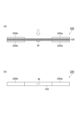
- FIG. 1 shows a connector used in appearance evaluation.
- FIG. 13 is a photograph showing a reinforcing member of the connector;
- FIG. 13 is a photograph showing a reinforcing member of the connector;
- FIG. 13 is a photograph showing a reinforcing member of the connector;
- the term "A or more” in a numerical range means A and a range exceeding A.
- the term "A or less” in a numerical range means A and a range less than A.
- the upper or lower limit of a numerical range in a certain stage can be arbitrarily combined with the upper or lower limit of a numerical range in another stage.
- the upper or lower limit of the numerical range may be replaced with a value shown in the examples.
- “A or B” may include either A or B, or may include both. Unless otherwise specified, the materials exemplified in this specification may be used alone or in combination of two or more types.
- composition When a composition contains multiple substances corresponding to each component, the content of each component in the composition means the total amount of the multiple substances present in the composition, unless otherwise specified.
- process includes not only independent processes, but also processes that cannot be clearly distinguished from other processes as long as the intended effect of the process is achieved.
- (Meth)acrylic compound means at least one of an acrylic compound and the corresponding methacrylic compound. The same applies to other similar expressions such as "(meth)acryloyl group.”
- the spectral transmittance in this specification can be measured, for example, using a "UV-VIS-NIR spectrophotometer SolidSpec-3700i" manufactured by Shimadzu Corporation.
- the method for checking the reinforcement state is a method for checking the reinforcement state of a reinforcing member relative to a structure.
- the "reinforcement state” according to this embodiment refers to the state of stress distribution acting on the structure and the degree of progress of peeling.
- the method for checking the reinforcement state includes a reinforcement state checking step for checking the reinforcement state based on the discoloration of the reinforcing member when stress is generated in the reinforcing member, the reinforcing member including a glass fiber sheet, a first resin part covering at least a portion of the glass fiber sheet, and a second resin part covering at least a portion of the first resin part, the first resin part containing a cured product of a (meth)acrylic compound, and the second resin part containing a cured product of an epoxy compound.
- the inventors have discovered that in a reinforcing member comprising a glass fiber sheet, a first resin portion, and a second resin portion, when the first resin portion contains a cured product of a (meth)acrylic compound and the second resin portion contains a cured product of an epoxy compound, the reinforcing member is prone to discoloration (e.g., becoming cloudy) when stress is generated in the reinforcing member, and have discovered that the reinforcing state of the reinforcing member (stress distribution, degree of peeling, etc.) can be visualized using the discoloration of the reinforcing member when stress is generated in the reinforcing member as an indicator.
- discoloration e.g., becoming cloudy
- the reinforcement state of the reinforcing member (stress distribution, degree of peeling, etc.) is visualized using discoloration (e.g., clouding) of the reinforcing member when stress is generated in the reinforcing member as an indicator, and the reinforcement state can be checked simply by checking the discoloration of the reinforcing member, so that the reinforcement state of the reinforcing member can be checked by a simple method.
- the reinforcement state of the reinforcing member can be checked without performing any processing on the reinforcing member (e.g., processing to separate the reinforcing member from the structure) in order to check the reinforcement state of the reinforcing member.
- the method for checking the reinforcement state by using a glass fiber sheet as the fiber sheet, it is easier to visually check the base placed under the reinforcing member compared to using other fiber sheets such as a carbon fiber sheet, and excellent visibility of the base can be obtained.
- the reinforcement state is confirmed based on the discoloration of the reinforcing member when stress is generated in the reinforcing member.
- the stress generated in the reinforcing member is not particularly limited, and may be stress generated due to deformation of the reinforcing member, or stress generated due to external pressure.
- the discoloration of the reinforcing member may be clouding (whitening) of the reinforcing member.
- the reinforcement state of the reinforcing member placed on the surface of the structure can be confirmed.
- the discoloration phenomenon of the reinforcing member can be confirmed by generating stress in the reinforcing member without placing the reinforcing member on the surface of the structure.
- the material, shape, and dimensions of the structure are not particularly limited.
- the structure may be a concrete structure.
- the reinforcing member includes a glass fiber sheet.
- the composition of the glass constituting the glass fiber sheet is not particularly limited, and examples include E glass, AR glass, S glass, C glass, D glass, ECR glass, etc.
- the glass fiber sheet may be a fiber fabric. Examples of the weave of the fiber fabric include plain weave, twill weave, satin weave, and rib weave.
- the fineness of the glass fiber sheet may be 50 tex or more, 100 tex or more, 500 tex or more, 1000 tex or more, 1500 tex or more, or 2000 tex or more, from the viewpoint that openings are likely to occur between the fibers and therefore the resin material is easily impregnated, and workability is likely to be improved.
- the fineness of the glass fiber sheet may be 5000 tex or less, 4000 tex or less, 3000 tex or less, or 2500 tex or less, from the viewpoint that handleability is likely to be improved by increasing the fiber density.
- the fineness of the glass fiber sheet may be 50 to 5000 tex, 50 to 4000 tex, 50 to 3000 tex, 500 to 5000 tex, 500 to 4000 tex, 500 to 3000 tex, 1500 to 5000 tex, 1500 to 4000 tex, or 1500 to 3000 tex.
- the fineness may be an average fineness, and the average fineness may be an average value of five measurement points.
- the basis weight of the glass fiber sheet (the content of the glass fiber sheet in the reinforcing member) may be in the following ranges. From the viewpoint of the reinforcing member being easily discolored (e.g., clouded) when stress is generated in the reinforcing member, and from the viewpoint of easily obtaining excellent strength and elongation, the basis weight of the glass fiber sheet may be 100 g/m 2 or more, 150 g/m 2 or more, 200 g/m 2 or more, 250 g/m 2 or more, 300 g/m 2 or more, 350 g/m 2 or more, 400 g/m 2 or more, 450 g/m 2 or more, 500 g/m 2 or more, 550 g/m 2 or more, 600 g/m 2 or more, or 650 g/m 2 or more.
- the basis weight of the glass fiber sheet may be 1000 g/m2 or less, 950 g/ m2 or less, 900 g/m2 or less, 850 g/m2 or less , 800 g/m2 or less, 750 g/m2 or less, 700 g/m2 or less , or 650 g/ m2 or less , from the viewpoint of the reinforcing member being easily discolored (e.g., becoming cloudy) when stress is generated in the reinforcing member, and from the viewpoint of easily obtaining excellent visibility of the base.
- the basis weight of the glass fiber sheet may be 100-1000 g/m 2 , 100-900 g/m 2 , 100-800 g/m 2 , 300-1000 g/m 2 , 300-900 g/m 2 , 300-800 g/m 2 , 500-1000 g/m 2 , 500-900 g/m 2 , or 500-800 g/m 2 .
- the thickness of the glass fiber sheet in the reinforcing member may be in the following ranges. From the viewpoint of easily obtaining the reinforcing effect of the reinforcing member, the thickness of the glass fiber sheet may be 50 ⁇ m or more, 100 ⁇ m or more, 120 ⁇ m or more, 150 ⁇ m or more, or 170 ⁇ m or more. From the viewpoint of easily obtaining excellent substrate visibility, the thickness of the glass fiber sheet may be 400 ⁇ m or less, 350 ⁇ m or less, 300 ⁇ m or less, 250 ⁇ m or less, or 200 ⁇ m or less.
- the thickness of the glass fiber sheet may be 50 to 400 ⁇ m, 50 to 300 ⁇ m, 50 to 200 ⁇ m, 100 to 400 ⁇ m, 100 to 300 ⁇ m, 100 to 200 ⁇ m, 150 to 400 ⁇ m, 150 to 300 ⁇ m, or 150 to 200 ⁇ m.
- the thickness of the glass fiber sheet may be an average thickness, and the average thickness may be the average value of six measurement points. If the glass fiber sheet is a fiber fabric of intersecting threads (e.g., a plain weave fiber fabric having warp and weft threads), the average thickness may be the average value of a total of six measurement points, including three points where the threads intersect and three points where the threads do not intersect.
- the content of the glass fiber sheet in the reinforcing member may be within the following ranges based on the total amount of the reinforcing member. From the viewpoint of easily obtaining the reinforcing effect of the reinforcing member, the content of the glass fiber sheet may be 15 mass% or more, 20 mass% or more, 25 mass% or more, 30 mass% or more, 35 mass% or more, 40 mass% or more, or 45 mass% or more. From the viewpoint of easily obtaining excellent base visibility, the content of the glass fiber sheet may be 75 mass% or less, 70 mass% or less, 65 mass% or less, 60 mass% or less, 55 mass% or less, or 50 mass% or less.
- the content of the glass fiber sheet may be 15 to 75 mass%, 15 to 65 mass%, 15 to 55 mass%, 30 to 75 mass%, 30 to 65 mass%, 30 to 55 mass%, 40 to 75 mass%, 40 to 65 mass%, or 40 to 55 mass%.
- the reinforcing member includes a first resin portion that covers at least a portion of the glass fiber sheet.
- the first resin portion may cover a portion of the glass fiber sheet (a portion of the glass fiber sheet may be exposed from the first resin portion) or may cover the entire glass fiber sheet.
- the first resin portion may be layered.
- the first resin portion contains a cured product of a (meth)acrylic compound.
- the (meth)acrylic compound is a compound having a (meth)acryloyl group. According to the inventor's findings, when the first resin portion contains a cured product of a (meth)acrylic compound, the reinforcing member (particularly the first resin portion) is prone to discoloration (e.g., becoming cloudy) when stress is generated in the reinforcing member.
- the content of the cured (meth)acrylic compound in the first resin part may be 50% by mass or more, 60% by mass or more, 70% by mass or more, 80% by mass or more, or 90% by mass or more based on the entire first resin part, from the viewpoint that the reinforcing member is likely to discolor (e.g., become cloudy) when stress is applied to the reinforcing member.
- the first resin part may be substantially composed of the cured (meth)acrylic compound (substantially 100% by mass of the first resin part is the cured (meth)acrylic compound).
- the first resin part may contain components other than the cured product of the (meth)acrylic compound.
- Such components include fillers, curing accelerators, curing retarders, light stabilizers, light absorbers, antioxidants, deterioration inhibitors, pigments, dyes, silane coupling agents, defoamers, leveling agents, dispersants, rheology control agents, waxes, etc.
- the spectral transmittance in the visible light region (e.g., wavelength 550 nm) per 0.5 mm thickness of the first resin portion may be 30% or more, 40% or more, 50% or more, 60% or more, 70% or more, 75% or more, 80% or more, 85% or more, or 90% or more, from the viewpoint of easily obtaining excellent substrate visibility.
- the thickness of the first resin part in the reinforcing member may be in the following ranges.
- the thickness of the first resin part may be 50 ⁇ m or more, 100 ⁇ m or more, 150 ⁇ m or more, or 200 ⁇ m or more, from the viewpoint of easily obtaining a sufficient reinforcing effect of the reinforcing member and easily improving the handleability of the reinforcing member.
- the thickness of the first resin part may be 400 ⁇ m or less, 350 ⁇ m or less, 300 ⁇ m or less, 250 ⁇ m or less, or 200 ⁇ m or less, from the viewpoint of easily obtaining excellent visibility of the base and easily improving the handleability of the reinforcing member.
- the thickness of the first resin part may be 50 to 400 ⁇ m, 50 to 300 ⁇ m, 50 to 250 ⁇ m, 100 to 400 ⁇ m, 100 to 300 ⁇ m, 100 to 250 ⁇ m, 150 to 400 ⁇ m, 150 to 300 ⁇ m, or 150 to 250 ⁇ m.
- the thickness of the first resin part may be an average thickness, and the average thickness may be an average value of three measurement points.
- the content of the first resin part in the reinforcing member may be in the following range.
- the content of the first resin part may be 50 g/m 2 or more, 100 g/m 2 or more, 150 g/m 2 or more, or 200 g/m 2 or more from the viewpoint of easily obtaining the reinforcing effect of the reinforcing member and easily improving the handleability of the reinforcing member.
- the content of the first resin part may be 400 g/m 2 or less, 350 g/m 2 or less, 300 g/m 2 or less, 250 g/m 2 or less, or 200 g/m 2 or less from the viewpoint of easily obtaining excellent base visibility and easily improving the handleability of the reinforcing member.
- the content of the first resin part may be 50 to 400 g/m 2 , 50 to 300 g/m 2 , 50 to 250 g/m 2 , 100 to 400 g/m 2 , 100 to 300 g/m 2 , 100 to 250 g/m 2 , 150 to 400 g/m 2 , 150 to 300 g/m 2 , or 150 to 250 g/m 2 .
- the content of the first resin part in the reinforcing member may be within the following ranges based on the total amount of the reinforcing member. From the viewpoint of easily obtaining a sufficient reinforcing effect of the reinforcing member and easily improving the handleability of the reinforcing member, the content of the first resin part may be 1 mass% or more, 3 mass% or more, 5 mass% or more, 8 mass% or more, 10 mass% or more, 12 mass% or more, or 14 mass% or more.
- the content of the first resin part may be 30 mass% or less, 25 mass% or less, 22 mass% or less, 20 mass% or less, 18 mass% or less, or 15 mass% or less. From these perspectives, the content of the first resin part may be 1 to 30% by mass, 1 to 25% by mass, 1 to 20% by mass, 5 to 30% by mass, 5 to 25% by mass, 5 to 20% by mass, 10 to 30% by mass, 10 to 25% by mass, or 10 to 20% by mass.
- the content of the first resin part in the reinforcing member may be in the following ranges per 100 parts by mass of the glass fiber sheet. From the viewpoint of easily obtaining a sufficient reinforcing effect of the reinforcing member and easily improving the handleability of the reinforcing member, the content of the first resin part may be 1 part by mass or more, 5 parts by mass or more, 10 parts by mass or more, 15 parts by mass or more, 20 parts by mass or more, 25 parts by mass or more, or 30 parts by mass or more.
- the content of the first resin part may be 60 parts by mass or less, 55 parts by mass or less, 50 parts by mass or less, 45 parts by mass or less, 40 parts by mass or less, or 35 parts by mass or less. From these viewpoints, the content of the first resin part may be 1 to 60 parts by mass, 1 to 50 parts by mass, 1 to 40 parts by mass, 5 to 60 parts by mass, 5 to 50 parts by mass, 5 to 40 parts by mass, 15 to 60 parts by mass, 15 to 50 parts by mass, or 15 to 40 parts by mass.
- the reinforcing member includes a second resin part covering at least a portion of the first resin part.
- the second resin part may cover a portion of the first resin part (a portion of the first resin part may be exposed from the second resin part) or may cover the entire first resin part.
- the second resin part may be disposed on at least one surface side selected from the group consisting of one surface and the other surface of the glass fiber sheet.
- the second resin part may be layered.
- the second resin part contains a cured product of an epoxy compound (a compound containing an epoxy group).
- the cured product of the epoxy compound may be obtained by a one-component adhesive containing an epoxy compound, or may be obtained by a multiple-component adhesive (e.g., a two-component adhesive) having a first component containing an epoxy compound and a second component containing a curing agent.
- the cured product of the epoxy compound may be obtained by a room temperature curing adhesive containing an epoxy compound.
- the epoxy compound may be an epoxy resin.
- the epoxy compound include bisphenol A type epoxy resin, bisphenol F type epoxy resin, bisphenol A bis(polypropylene glycol glycidyl ether) ether, bisphenol A bis(polyethylene glycol glycidyl ether) ether, hydrogenated bisphenol A type epoxy resin, hydrogenated bisphenol F type epoxy resin, biphenyl type epoxy resin, urethane modified epoxy resin, rubber modified epoxy resin, alkyl glycidyl ether, cresyl glycidyl ether, phenyl glycidyl ether, alkyl diglycidyl ether, polyethylene glycol diglycidyl ether, polypropylene glycol diglycidyl ether, glycerin triglycidyl ether, trimethylolpropane triglycidyl ether, diglycidyl ether of alkanediol, etc.
- the epoxy compound may include a compound having a bisphenol A skeleton, may include a bisphenol A type epoxy resin, or may include an alkylene oxide-added bisphenol A type epoxy resin (for example, a propylene oxide-added bisphenol A type epoxy resin).
- the content of the cured epoxy compound in the second resin part may be 50% by mass or more, 60% by mass or more, 70% by mass or more, 80% by mass or more, or 90% by mass or more based on the entire second resin part, from the viewpoint of easily obtaining a sufficient reinforcing effect of the reinforcing member.
- the second resin part may be substantially composed of the cured epoxy compound (substantially 100% by mass of the second resin part is the cured epoxy compound).
- the second resin part may contain components other than the cured product of the epoxy compound.
- Such components include fillers (e.g., silica), curing accelerators, curing retarders, light stabilizers, light absorbers, antioxidants, anti-degradation agents, pigments, dyes, silane coupling agents, defoamers, leveling agents, dispersants, rheology control agents, waxes, etc.
- the spectral transmittance in the visible light region (e.g., wavelength 550 nm) per 0.5 mm thickness of the second resin portion may be 30% or more, 40% or more, 50% or more, 60% or more, 70% or more, 75% or more, 80% or more, 85% or more, or 90% or more, from the viewpoint of easily obtaining excellent substrate visibility.
- the thickness of the second resin portion in the reinforcing member may be in the following ranges. From the viewpoint of easily obtaining a sufficient reinforcing effect of the reinforcing member, the thickness of the second resin portion may be 100 ⁇ m or more, 200 ⁇ m or more, 300 ⁇ m or more, 400 ⁇ m or more, 450 ⁇ m or more, or 500 ⁇ m or more. From the viewpoint of easily obtaining excellent substrate visibility, the thickness of the second resin portion may be 800 ⁇ m or less, 700 ⁇ m or less, 600 ⁇ m or less, 550 ⁇ m or less, or 500 ⁇ m or less.
- the thickness of the second resin part may be 100 to 800 ⁇ m, 100 to 700 ⁇ m, 100 to 600 ⁇ m, 300 to 800 ⁇ m, 300 to 700 ⁇ m, 300 to 600 ⁇ m, 400 to 800 ⁇ m, 400 to 700 ⁇ m, or 400 to 600 ⁇ m.
- the thickness of the second resin part may be an average thickness, and the average thickness may be an average value of six measurement points.
- the thickness of the second resin part may be an average value of the thickness of the second resin part on one side of the glass fiber sheet and the thickness of the second resin part on the other side of the glass fiber sheet, and may be an average value of three measurement points on each of the one side and the other side.
- the content of the second resin portion in the reinforcing member may be in the following range.
- the content of the second resin portion may be 100 g/m 2 or more, 200 g/m 2 or more, 300 g/m 2 or more, 400 g/m 2 or more, 450 g/m 2 or more, or 500 g/m 2 or more from the viewpoint of easily obtaining the reinforcing effect of the reinforcing member.
- the content of the second resin portion may be 800 g/m 2 or less, 700 g/m 2 or less, 600 g/m 2 or less, 550 g/m 2 or less, or 500 g/m 2 or less from the viewpoint of easily obtaining excellent base visibility.
- the content of the second resin part may be 100 to 800 g/m 2 , 100 to 700 g/m 2 , 100 to 600 g/m 2 , 300 to 800 g/m 2 , 300 to 700 g/m 2 , 300 to 600 g/m 2 , 400 to 800 g/m 2 , 400 to 700 g/m 2 , or 400 to 600 g/m 2 .
- the content of the second resin part in the reinforcing member may be within the following ranges based on the total amount of the reinforcing member. From the viewpoint of easily obtaining a sufficient reinforcing effect of the reinforcing member, the content of the second resin part may be 1 mass% or more, 5 mass% or more, 10 mass% or more, 15 mass% or more, 20 mass% or more, 25 mass% or more, 30 mass% or more, or 35 mass% or more. From the viewpoint of easily obtaining excellent base visibility, the content of the second resin part may be 70 mass% or less, 65 mass% or less, 60 mass% or less, 55 mass% or less, 50 mass% or less, 45 mass% or less, or 40 mass% or less.
- the content of the second resin part may be 1 to 70 mass%, 1 to 60 mass%, 1 to 50 mass%, 10 to 70 mass%, 10 to 60 mass%, 10 to 50 mass%, 20 to 70 mass%, 20 to 60 mass%, or 20 to 50 mass%.
- the content of the second resin part in the reinforcing member may be in the following ranges per 100 parts by mass of the glass fiber sheet. From the viewpoint of easily obtaining a sufficient reinforcing effect of the reinforcing member, the content of the second resin part may be 10 parts by mass or more, 20 parts by mass or more, 30 parts by mass or more, 40 parts by mass or more, 50 parts by mass or more, 60 parts by mass or more, 65 parts by mass or more, 70 parts by mass or more, or 75 parts by mass or more. From the viewpoint of easily obtaining excellent base visibility, the content of the second resin part may be 250 parts by mass or less, 200 parts by mass or less, 150 parts by mass or less, 100 parts by mass or less, 90 parts by mass or less, or 80 parts by mass or less.
- the content of the second resin part may be 10 to 250 parts by mass, 10 to 150 parts by mass, 10 to 100 parts by mass, 30 to 250 parts by mass, 30 to 150 parts by mass, 30 to 100 parts by mass, 50 to 250 parts by mass, 50 to 150 parts by mass, or 50 to 100 parts by mass.
- the content of the second resin part in the reinforcing member may be in the following ranges relative to 100 parts by mass of the first resin part. From the viewpoint of easily obtaining a sufficient reinforcing effect of the reinforcing member, the content of the second resin part may be 50 parts by mass or more, 80 parts by mass or more, 100 parts by mass or more, 120 parts by mass or more, 150 parts by mass or more, 180 parts by mass or more, 200 parts by mass or more, 220 parts by mass or more, or 250 parts by mass or more.
- the content of the second resin part may be 850 parts by mass or less, 800 parts by mass or less, 700 parts by mass or less, 600 parts by mass or less, 500 parts by mass or less, 450 parts by mass or less, 400 parts by mass or less, 350 parts by mass or less, 300 parts by mass or less, or 250 parts by mass or less. From these viewpoints, the content of the second resin part may be 50 to 850 parts by mass, 50 to 550 parts by mass, 50 to 350 parts by mass, 100 to 850 parts by mass, 100 to 550 parts by mass, 100 to 350 parts by mass, 150 to 850 parts by mass, 150 to 550 parts by mass, or 150 to 350 parts by mass.
- the reinforcing member may further include a member other than the glass fiber sheet, the first resin part, and the second resin part.
- the reinforcing member may include a member (e.g., an undercoat layer formed by a primer) disposed between the second resin part and the structure, and may include a member (e.g., an overcoat layer such as a protective coating or a topcoat layer) disposed on the opposite side of the glass fiber sheet from the structure.
- the spectral transmittance of the reinforcing member in the visible light region (e.g., wavelength 550 nm) per 0.8 mm thickness may be 10% or more, 15% or more, 20% or more, 25% or more, 30% or more, 35% or more, or 40% or more, from the viewpoint of easily obtaining excellent visibility of the substrate.
- the thickness of the reinforcing member may be in the following ranges. From the viewpoint of easily obtaining the reinforcing effect of the reinforcing member, the thickness of the reinforcing member may be 200 ⁇ m or more, 300 ⁇ m or more, 400 ⁇ m or more, 500 ⁇ m or more, 600 ⁇ m or more, 700 ⁇ m or more, or 800 ⁇ m or more. From the viewpoint of easily obtaining excellent visibility of the base, the thickness of the reinforcing member may be 1500 ⁇ m or less, 1200 ⁇ m or less, 1000 ⁇ m or less, 900 ⁇ m or less, or 800 ⁇ m or less.
- the thickness of the reinforcing member may be 200 to 1500 ⁇ m, 200 to 1200 ⁇ m, 200 to 1000 ⁇ m, 400 to 1500 ⁇ m, 400 to 1200 ⁇ m, 400 to 1000 ⁇ m, 600 to 1500 ⁇ m, 600 to 1200 ⁇ m, or 600 to 1000 ⁇ m.
- the thickness of the reinforcing member may be an average thickness, and the average thickness may be an average value of three measurement points.
- the tensile modulus of the reinforcing member may be 50 GPa or more, 60 GPa or more, 70 GPa or more, 80 GPa or more, or 90 GPa or more, from the viewpoint of easily obtaining a sufficient reinforcing effect of the reinforcing member.
- the tensile modulus of the reinforcing member may be 150 GPa or less, 130 GPa or less, 120 GPa or less, 100 GPa or less, or 90 GPa or less, from the viewpoint of easily obtaining a sufficient adhesive force of the reinforcing member.
- the tensile modulus of the reinforcing member may be 50 to 150 GPa, 50 to 120 GPa, 50 to 100 GPa, 60 to 150 GPa, 60 to 120 GPa, 60 to 100 GPa, 80 to 150 GPa, 80 to 120 GPa, or 80 to 100 GPa.
- the tensile modulus of the reinforcing member may be the tensile modulus at 25°C.
- the tensile modulus of the reinforcing member can be measured in accordance with JIS A1191 (Method B).
- the reinforcing member 100 in FIG. 1 includes a glass fiber sheet 10, a layered first resin portion 20 that covers the glass fiber sheet 10, and a layered second resin portion 30 that covers the first resin portion 20.
- a cross section of each fiber that constitutes the glass fiber sheet 10 is shown, and the entire glass fiber sheet 10 is covered with the first resin portion 20.
- the first resin portion 20 is in contact with the glass fiber sheet 10 and contains a cured product of a (meth)acrylic compound.
- the second resin portion 30 is in contact with the first resin portion 20 and contains a cured product of an epoxy compound.
- the second resin portion 30 is disposed on both sides of the glass fiber sheet 10, and the entire first resin portion 20 is covered with the second resin portion 30.
- the method for manufacturing the reinforcing member includes, in this order, a first coating step of coating at least a portion of the glass fiber sheet with a first resin material containing a (meth)acrylic compound, a first curing step of obtaining a first resin part by curing the first resin material, a second coating step of coating at least a portion of the first resin part with a second resin material containing an epoxy compound, and a second curing step of obtaining a second resin part by curing the second resin material.
- the method of supplying the first resin material to the glass fiber sheet in the first coating process and the method of supplying the second resin material to the first resin part in the second coating process are not particularly limited.
- the resin material (the first resin material or the second resin material) may be cured by heat, light, or the like, or the resin material (the first resin material or the second resin material) may be cured at room temperature (e.g., multiple materials are mixed and then cured at room temperature).
- the method for checking the reinforcement state may include a reinforcing step of reinforcing the structure with a reinforcing member prior to the reinforcement state checking step.
- a member to be reinforced can be placed on the surface of the structure.
- a (meth)acrylic composition was prepared by mixing 70 parts by mass of bisphenol A ethylene oxide-modified (4 mol addition) dimethacrylate ((meth)acrylic compound, manufactured by MIWON Corporation, product name "Miramer M241”), 30 parts by mass of bisphenol A ethylene oxide-modified (10 mol addition) dimethacrylate ((meth)acrylic compound, manufactured by MIWON Corporation, product name "Miramer M2101”), and 3 parts by mass of 1-hydroxycyclohexyl phenyl ketone (photopolymerization initiator, manufactured by IGM Resins, product name "Omnirad 184”) in a container to obtain a mixture, and then stirring the mixture.
- Example 1 A two-way plain weave glass fiber sheet (average fineness: 2400 tex, basis weight: 650 g/m 2 ) was coated with 200 g/m 2 of the above-mentioned (meth)acrylic composition to impregnate the glass fiber sheet with the (meth)acrylic composition.
- the (meth)acrylic composition was cured by irradiating it with ultraviolet light (wavelength: 365 nm) at an illuminance of 200 mW/cm 2 and an exposure dose of 8000 mJ/cm 2 using a UV-LED irradiation device, thereby obtaining a resin-impregnated sheet comprising the glass fiber sheet and a first resin portion (cured product of the (meth)acrylic composition containing a (meth)acrylic compound) covering the glass fiber sheet.
- ultraviolet light wavelength: 365 nm
- the content of the glass fiber sheet was 650 g/m 2
- the content of the first resin part was 200 g/m 2
- the content of the second resin part was 500 g/m 2.
- the content of the glass fiber sheet was 48.2 mass%
- the content of the first resin part was 14.8 mass%
- the content of the second resin part was 37.0 mass%.
- the spectral transmittance of the first resin part and the second resin part at a wavelength of 550 nm per 0.5 mm thickness was 90%.
- the spectral transmittance of the reinforcing member at a wavelength of 550 nm per 0.8 mm thickness was 43%.
- FIG. 2 shows the connector used in the appearance evaluation, where (a) in FIG. 2 is a side view of the connector, and (b) in FIG. 2 is a plan view of the connector viewed from the front side (the direction of the arrow in the center of (a) in FIG. 2). As shown in FIG.
- FIG. 3 shows photographs of the reinforcing member of the connector observed from the back side of the connector (the direction opposite to the arrow in the center of Figure 2(a)) ((a) Example 1, (b) Comparative Example 1, (c) Comparative Example 2).
- wiring is connected to a mark M placed in the center of one side of the reinforcing member and fixed with tape.
- the reinforcing member is transparent, whereas in Comparative Example 2, the reinforcing member is not transparent because a black carbon fiber sheet is used.
- the tensile modulus of the reinforcing member was calculated by dividing the difference in stress between two points at 20% and 50% of the maximum tensile stress by the difference in strain between two points at 20% and 50% of the maximum tensile load, based on the stress-strain curve in an FRP tensile strength test conforming to JIS A1191 (Method B).
- the tensile modulus of the reinforcing member in Example 1 was 90 GPa.
- Figures 4 and 5 are photographs of the reinforcing member of the connector observed from the surface side of the connector (the direction of the central arrow in (a) of Figure 2) ( Figure 4: Example 1, Figure 5: Comparative Example 1).
- (a) of Figure 4 and Figure 5 shows the observation results before stress generation
- (b) of Figure 4 and Figure 5 shows the observation results when a load of 3 kN is applied.
- Example 1 the reinforcing member (particularly the first resin part) was visually observed to become cloudy as stress was generated, and the behavior of the stress could be visually confirmed.
- Comparative Example 1 no change in appearance was visually observed before and after stress generation until the reinforcing member broke when the fracture strain was reached, and the behavior of the stress could not be visually confirmed.
- Comparative Example 2 no change in appearance was visually observed before and after stress generation until the reinforcing member broke when the fracture strain was reached, and the behavior of the stress could not be visually confirmed.
- REFERENCE SIGNS LIST 10 glass fiber sheet, 20...first resin part, 30...second resin part, 100...reinforcing member, 200...connecting body, 200a, 200b...aluminum tabs, M...mark.
Landscapes
- Engineering & Computer Science (AREA)
- Architecture (AREA)
- Chemical & Material Sciences (AREA)
- Chemical Kinetics & Catalysis (AREA)
- Electrochemistry (AREA)
- Mechanical Engineering (AREA)
- Civil Engineering (AREA)
- Structural Engineering (AREA)
- Reinforced Plastic Materials (AREA)
- Laminated Bodies (AREA)
- Compositions Of Macromolecular Compounds (AREA)
Abstract
Description
[1]構造物に対する補強部材の補強状態の確認方法であって、前記補強部材に応力が生じた際の前記補強部材の変色に基づき補強状態を確認する工程を備え、前記補強部材が、ガラス繊維シートと、当該ガラス繊維シートの少なくとも一部を被覆する第1の樹脂部と、当該第1の樹脂部の少なくとも一部を被覆する第2の樹脂部と、を備え、前記第1の樹脂部が(メタ)アクリル化合物の硬化物を含有し、前記第2の樹脂部がエポキシ化合物の硬化物を含有する、補強状態の確認方法。
[2]前記ガラス繊維シートの目付量が100~1000g/m2である、[1]に記載の補強状態の確認方法。
[3]前記補強部材の引張弾性率が50~150GPaである、[1]又は[2]に記載の補強状態の確認方法。
[4]前記構造物がコンクリート構造物である、[1]~[3]のいずれか一つに記載の補強状態の確認方法。
ビスフェノールAエチレンオキサイド変性(4mol付加)ジメタクリレート((メタ)アクリル化合物、MIWON社製、商品名「Miramer M241」)70質量部、ビスフェノールAエチレンオキサイド変性(10mol付加)ジメタクリレート((メタ)アクリル化合物、MIWON社製、商品名「Miramer M2101」)30質量部、及び、1-ヒドロキシシクロヘキシルフェニルケトン(光重合開始剤、IGM Resins社製、商品名「Omnirad 184」)3質量部を容器中で混合することにより混合物を得た後にこの混合物を撹拌することにより(メタ)アクリル組成物を調製した。
ビスフェノールA型エポキシ樹脂(エポキシ化合物、株式会社ADEKA製、商品名「アデカレジンEP-4100」)70質量部、プロピレンオキサイド付加ビスフェノールA型エポキシ樹脂(エポキシ化合物、株式会社ADEKA製、商品名「アデカレジンEP-4005」)15質量部、1,6-ヘキサンジオールのジグリシジルエーテル(株式会社ADEKA製、商品名「アデカグリシロールED-503」)15質量部、及び、親水性フュームドシリカ(日本アエロジル株式会社製、商品名「アエロジル200」)4質量部を容器中で混合することにより混合物を得た後にこの混合物を撹拌することにより主剤を調製した。また、ポリアミン化合物(株式会社T&K TOKA製、商品名「フジキュア8106-A」)42質量部、及び、アミド系増粘剤(ビックケミージャパン株式会社製、商品名「BYK R607」)2質量部を容器中で混合することにより混合物を得た後にこの混合物を撹拌することにより硬化剤を調製した。
(実施例1)
2方向平織のガラス繊維シート(平均繊度:2400tex、目付量:650g/m2)に上述の(メタ)アクリル組成物200g/m2を塗布することによりガラス繊維シートに(メタ)アクリル組成物を含浸させた。次に、UV-LED照射装置を用いて照度200mW/cm2、照射量8000mJ/cm2の紫外線(波長:365nm)を照射して(メタ)アクリル組成物を硬化させることにより、ガラス繊維シートと、ガラス繊維シートを被覆する第1の樹脂部((メタ)アクリル化合物を含有する(メタ)アクリル組成物の硬化物)と、を備える樹脂含浸シートを得た。
2方向平織のガラス繊維シート(実施例1と同様)に、上述の2剤常温硬化型エポキシ組成物の主剤及び硬化剤を予め混合することにより得られたエポキシ組成物(主剤:硬化剤=2:1[質量比])500g/m2を塗布した。次に、空気中、常温(25℃)で1週間エポキシ組成物を硬化させることにより、ガラス繊維シートと、ガラス繊維シートを被覆する樹脂部(エポキシ化合物を含有するエポキシ組成物の硬化物)と、を備える補強部材を得た。
1方向の高強度炭素繊維シート(東レ株式会社製、商品名「トレカクロスUT70-20G」、目付量:200g/m2)に、上述の2剤常温硬化型エポキシ組成物の主剤及び硬化剤を予め混合することにより得られたエポキシ組成物(主剤:硬化剤=2:1[質量比])500g/m2を塗布した。次に、空気中、常温(25℃)で1週間エポキシ組成物を硬化させることにより、炭素繊維シートと、炭素繊維シートを被覆する樹脂部(エポキシ化合物を含有するエポキシ組成物の硬化物)と、を備える補強部材を得た。
(応力発生前)
図2は、外観評価に用いた接続体を示す図であり、図2の(a)は接続体の側面図であり、図2の(b)は接続体の表面側(図2の(a)の中央の矢印の方向)から接続体を見た平面図である。図2に示すように、補強部材100(実施例1、比較例1又は比較例2の補強部材、長さ:350mm、幅:20mm)の一端部の両面を一対のアルミニウムタブ200aで把持し、補強部材100の他端部の両面を一対のアルミニウムタブ200bで把持し、補強部材100の一方面の中央に目印Mを配置することにより接続体200を得た。アルミニウムタブ200a,200bについて、長さは100mmであり、幅は20mmであり、厚さは2mmであった。
上述の接続体の長手方向が鉛直方向に向いた状態で、300kN万能試験機(株式会社島津製作所製、オートグラフAG-300KG)を用いて接続体の一方端及び他方端のアルミニウムタブを把持した後、JIS A1191(B法)を参考にFRP引張強度試験を接続体の補強部材に施すことにより、補強部材の長さ方向の応力を補強部材において生じさせた。クロスヘッドの変位制御(引張速度:3.0mm/分)により単調に応力を加えつつ、補強部材(実施例)の引張弾性率を測定すると共に、補強部材(実施例及び比較例)の面に垂直な方向から補強部材を観察した。
Claims (4)
- 構造物に対する補強部材の補強状態の確認方法であって、
前記補強部材に応力が生じた際の前記補強部材の変色に基づき補強状態を確認する工程を備え、
前記補強部材が、ガラス繊維シートと、当該ガラス繊維シートの少なくとも一部を被覆する第1の樹脂部と、当該第1の樹脂部の少なくとも一部を被覆する第2の樹脂部と、を備え、
前記第1の樹脂部が(メタ)アクリル化合物の硬化物を含有し、
前記第2の樹脂部がエポキシ化合物の硬化物を含有する、補強状態の確認方法。 - 前記ガラス繊維シートの目付量が100~1000g/m2である、請求項1に記載の補強状態の確認方法。
- 前記補強部材の引張弾性率が50~150GPaである、請求項1に記載の補強状態の確認方法。
- 前記構造物がコンクリート構造物である、請求項1~3のいずれか一項に記載の補強状態の確認方法。
Priority Applications (1)
| Application Number | Priority Date | Filing Date | Title |
|---|---|---|---|
| JP2025510475A JPWO2024203402A1 (ja) | 2023-03-30 | 2024-03-14 |
Applications Claiming Priority (2)
| Application Number | Priority Date | Filing Date | Title |
|---|---|---|---|
| JP2023054866 | 2023-03-30 | ||
| JP2023-054866 | 2023-03-30 |
Publications (1)
| Publication Number | Publication Date |
|---|---|
| WO2024203402A1 true WO2024203402A1 (ja) | 2024-10-03 |
Family
ID=92906040
Family Applications (1)
| Application Number | Title | Priority Date | Filing Date |
|---|---|---|---|
| PCT/JP2024/010075 Ceased WO2024203402A1 (ja) | 2023-03-30 | 2024-03-14 | 構造物に対する補強部材の補強状態の確認方法 |
Country Status (2)
| Country | Link |
|---|---|
| JP (1) | JPWO2024203402A1 (ja) |
| WO (1) | WO2024203402A1 (ja) |
Citations (5)
| Publication number | Priority date | Publication date | Assignee | Title |
|---|---|---|---|---|
| JPH093745A (ja) * | 1995-06-19 | 1997-01-07 | Toray Ind Inc | 補強繊維シートおよびコンクリート構造物 |
| JP2000265680A (ja) * | 1999-01-12 | 2000-09-26 | East Japan Railway Co | 耐震補強方法 |
| JP2010001707A (ja) * | 2008-06-23 | 2010-01-07 | Mbs Inc | コンクリート構造物表面の強化コーティング方法 |
| JP2016030716A (ja) * | 2014-07-30 | 2016-03-07 | アイカ工業株式会社 | コンクリート片剥落防止構造及びこの剥落防止工法及びこれらに使用する脂環式ポリアミン |
| WO2021039858A1 (ja) * | 2019-08-27 | 2021-03-04 | デンカ株式会社 | コンクリート構造物補強用繊維シート |
-
2024
- 2024-03-14 JP JP2025510475A patent/JPWO2024203402A1/ja active Pending
- 2024-03-14 WO PCT/JP2024/010075 patent/WO2024203402A1/ja not_active Ceased
Patent Citations (5)
| Publication number | Priority date | Publication date | Assignee | Title |
|---|---|---|---|---|
| JPH093745A (ja) * | 1995-06-19 | 1997-01-07 | Toray Ind Inc | 補強繊維シートおよびコンクリート構造物 |
| JP2000265680A (ja) * | 1999-01-12 | 2000-09-26 | East Japan Railway Co | 耐震補強方法 |
| JP2010001707A (ja) * | 2008-06-23 | 2010-01-07 | Mbs Inc | コンクリート構造物表面の強化コーティング方法 |
| JP2016030716A (ja) * | 2014-07-30 | 2016-03-07 | アイカ工業株式会社 | コンクリート片剥落防止構造及びこの剥落防止工法及びこれらに使用する脂環式ポリアミン |
| WO2021039858A1 (ja) * | 2019-08-27 | 2021-03-04 | デンカ株式会社 | コンクリート構造物補強用繊維シート |
Also Published As
| Publication number | Publication date |
|---|---|
| JPWO2024203402A1 (ja) | 2024-10-03 |
Similar Documents
| Publication | Publication Date | Title |
|---|---|---|
| US10981364B2 (en) | Decorated sheet | |
| KR101653416B1 (ko) | 편광판, 광학 부재 및 액정 표시 장치 | |
| EP2682429B1 (en) | Method for producing a prepreg | |
| TWI578030B (zh) | Polarizing plate, composite polarizing plate and liquid crystal display device | |
| US20150148451A1 (en) | Epoxy resin composition | |
| CN101175627A (zh) | 制造含有无机纤维的复合光学体的方法 | |
| WO2005045486A1 (ja) | 積層フィルム | |
| WO2005040256A1 (ja) | 光学用樹脂シート及び該光学用樹脂シートを含む液晶セル基板、液晶表示装置、画像表示装置用基板、画像表示装置 | |
| US20240262091A1 (en) | Cosmetic sheet and cosmetic plate | |
| CN104371488A (zh) | 紫外光固化复合材料快速粘接修理方法 | |
| WO2024203402A1 (ja) | 構造物に対する補強部材の補強状態の確認方法 | |
| JP6776673B2 (ja) | 不燃性透明複合シート | |
| JP7272406B2 (ja) | シートモールディングコンパウンド及び成形品の製造方法 | |
| JP6287074B2 (ja) | 樹脂シート、およびそれを用いた繊維強化複合成形体の製造方法 | |
| EP3753727A1 (en) | Decorative sheet and decorative board | |
| JP2006104394A (ja) | 保護フィルム付光硬化性プリプレグシート | |
| JP7464173B2 (ja) | 保護フィルムおよびその製造方法 | |
| JP4356395B2 (ja) | プラスチック複合透明シート及びそれを使用した表示素子 | |
| JP2014226914A (ja) | 透明不燃性シートとその製造方法 | |
| DE102023106638A1 (de) | Mehrschicht-Klebeverbindung mit axialem Gradienten der Wärmeausdehnungskoeffizienten | |
| JP2022154385A (ja) | 活性エネルギー線硬化性接着剤組成物、偏光板用接着剤組成物、偏光板用接着剤、偏光板 | |
| JP5243174B2 (ja) | 光硬化性プリプレグシート | |
| KR102693392B1 (ko) | 내식성 광경화형 보강재 | |
| CN113498380A (zh) | 装饰片 | |
| JP2016018109A (ja) | ガラス繊維強化樹脂シート |
Legal Events
| Date | Code | Title | Description |
|---|---|---|---|
| 121 | Ep: the epo has been informed by wipo that ep was designated in this application |
Ref document number: 24779531 Country of ref document: EP Kind code of ref document: A1 |
|
| ENP | Entry into the national phase |
Ref document number: 2025510475 Country of ref document: JP Kind code of ref document: A |
|
| WWE | Wipo information: entry into national phase |
Ref document number: 2025510475 Country of ref document: JP |
|
| NENP | Non-entry into the national phase |
Ref country code: DE |
|
| 122 | Ep: pct application non-entry in european phase |
Ref document number: 24779531 Country of ref document: EP Kind code of ref document: A1 |