WO2024203365A1 - 粘着シートの製造方法、粘着シート付き光学フィルムの製造方法及び画像表示装置の製造方法 - Google Patents
粘着シートの製造方法、粘着シート付き光学フィルムの製造方法及び画像表示装置の製造方法 Download PDFInfo
- Publication number
- WO2024203365A1 WO2024203365A1 PCT/JP2024/009901 JP2024009901W WO2024203365A1 WO 2024203365 A1 WO2024203365 A1 WO 2024203365A1 JP 2024009901 W JP2024009901 W JP 2024009901W WO 2024203365 A1 WO2024203365 A1 WO 2024203365A1
- Authority
- WO
- WIPO (PCT)
- Prior art keywords
- light
- adhesive sheet
- less
- meth
- coating layer
- Prior art date
- Legal status (The legal status is an assumption and is not a legal conclusion. Google has not performed a legal analysis and makes no representation as to the accuracy of the status listed.)
- Ceased
Links
Images



Classifications
-
- B—PERFORMING OPERATIONS; TRANSPORTING
- B05—SPRAYING OR ATOMISING IN GENERAL; APPLYING FLUENT MATERIALS TO SURFACES, IN GENERAL
- B05D—PROCESSES FOR APPLYING FLUENT MATERIALS TO SURFACES, IN GENERAL
- B05D3/00—Pretreatment of surfaces to which liquids or other fluent materials are to be applied; After-treatment of applied coatings, e.g. intermediate treating of an applied coating preparatory to subsequent applications of liquids or other fluent materials
- B05D3/06—Pretreatment of surfaces to which liquids or other fluent materials are to be applied; After-treatment of applied coatings, e.g. intermediate treating of an applied coating preparatory to subsequent applications of liquids or other fluent materials by exposure to radiation
- B05D3/061—Pretreatment of surfaces to which liquids or other fluent materials are to be applied; After-treatment of applied coatings, e.g. intermediate treating of an applied coating preparatory to subsequent applications of liquids or other fluent materials by exposure to radiation using U.V.
- B05D3/065—After-treatment
- B05D3/067—Curing or cross-linking the coating
-
- C—CHEMISTRY; METALLURGY
- C08—ORGANIC MACROMOLECULAR COMPOUNDS; THEIR PREPARATION OR CHEMICAL WORKING-UP; COMPOSITIONS BASED THEREON
- C08F—MACROMOLECULAR COMPOUNDS OBTAINED BY REACTIONS ONLY INVOLVING CARBON-TO-CARBON UNSATURATED BONDS
- C08F220/00—Copolymers of compounds having one or more unsaturated aliphatic radicals, each having only one carbon-to-carbon double bond, and only one being terminated by only one carboxyl radical or a salt, anhydride ester, amide, imide or nitrile thereof
- C08F220/02—Monocarboxylic acids having less than ten carbon atoms; Derivatives thereof
- C08F220/04—Acids; Metal salts or ammonium salts thereof
- C08F220/06—Acrylic acid; Methacrylic acid; Metal salts or ammonium salts thereof
-
- C—CHEMISTRY; METALLURGY
- C08—ORGANIC MACROMOLECULAR COMPOUNDS; THEIR PREPARATION OR CHEMICAL WORKING-UP; COMPOSITIONS BASED THEREON
- C08F—MACROMOLECULAR COMPOUNDS OBTAINED BY REACTIONS ONLY INVOLVING CARBON-TO-CARBON UNSATURATED BONDS
- C08F220/00—Copolymers of compounds having one or more unsaturated aliphatic radicals, each having only one carbon-to-carbon double bond, and only one being terminated by only one carboxyl radical or a salt, anhydride ester, amide, imide or nitrile thereof
- C08F220/02—Monocarboxylic acids having less than ten carbon atoms; Derivatives thereof
- C08F220/10—Esters
- C08F220/12—Esters of monohydric alcohols or phenols
- C08F220/16—Esters of monohydric alcohols or phenols of phenols or of alcohols containing two or more carbon atoms
- C08F220/18—Esters of monohydric alcohols or phenols of phenols or of alcohols containing two or more carbon atoms with acrylic or methacrylic acids
- C08F220/1804—C4-(meth)acrylate, e.g. butyl (meth)acrylate, isobutyl (meth)acrylate or tert-butyl (meth)acrylate
-
- C—CHEMISTRY; METALLURGY
- C08—ORGANIC MACROMOLECULAR COMPOUNDS; THEIR PREPARATION OR CHEMICAL WORKING-UP; COMPOSITIONS BASED THEREON
- C08F—MACROMOLECULAR COMPOUNDS OBTAINED BY REACTIONS ONLY INVOLVING CARBON-TO-CARBON UNSATURATED BONDS
- C08F220/00—Copolymers of compounds having one or more unsaturated aliphatic radicals, each having only one carbon-to-carbon double bond, and only one being terminated by only one carboxyl radical or a salt, anhydride ester, amide, imide or nitrile thereof
- C08F220/02—Monocarboxylic acids having less than ten carbon atoms; Derivatives thereof
- C08F220/10—Esters
- C08F220/20—Esters of polyhydric alcohols or phenols, e.g. 2-hydroxyethyl (meth)acrylate or glycerol mono-(meth)acrylate
-
- C—CHEMISTRY; METALLURGY
- C08—ORGANIC MACROMOLECULAR COMPOUNDS; THEIR PREPARATION OR CHEMICAL WORKING-UP; COMPOSITIONS BASED THEREON
- C08F—MACROMOLECULAR COMPOUNDS OBTAINED BY REACTIONS ONLY INVOLVING CARBON-TO-CARBON UNSATURATED BONDS
- C08F226/00—Copolymers of compounds having one or more unsaturated aliphatic radicals, each having only one carbon-to-carbon double bond, and at least one being terminated by a single or double bond to nitrogen or by a heterocyclic ring containing nitrogen
- C08F226/06—Copolymers of compounds having one or more unsaturated aliphatic radicals, each having only one carbon-to-carbon double bond, and at least one being terminated by a single or double bond to nitrogen or by a heterocyclic ring containing nitrogen by a heterocyclic ring containing nitrogen
- C08F226/10—N-Vinyl-pyrrolidone
-
- C—CHEMISTRY; METALLURGY
- C09—DYES; PAINTS; POLISHES; NATURAL RESINS; ADHESIVES; COMPOSITIONS NOT OTHERWISE PROVIDED FOR; APPLICATIONS OF MATERIALS NOT OTHERWISE PROVIDED FOR
- C09J—ADHESIVES; NON-MECHANICAL ASPECTS OF ADHESIVE PROCESSES IN GENERAL; ADHESIVE PROCESSES NOT PROVIDED FOR ELSEWHERE; USE OF MATERIALS AS ADHESIVES
- C09J11/00—Features of adhesives not provided for in group C09J9/00, e.g. additives
- C09J11/02—Non-macromolecular additives
- C09J11/06—Non-macromolecular additives organic
-
- C—CHEMISTRY; METALLURGY
- C09—DYES; PAINTS; POLISHES; NATURAL RESINS; ADHESIVES; COMPOSITIONS NOT OTHERWISE PROVIDED FOR; APPLICATIONS OF MATERIALS NOT OTHERWISE PROVIDED FOR
- C09J—ADHESIVES; NON-MECHANICAL ASPECTS OF ADHESIVE PROCESSES IN GENERAL; ADHESIVE PROCESSES NOT PROVIDED FOR ELSEWHERE; USE OF MATERIALS AS ADHESIVES
- C09J133/00—Adhesives based on homopolymers or copolymers of compounds having one or more unsaturated aliphatic radicals, each having only one carbon-to-carbon double bond, and at least one being terminated by only one carboxyl radical, or of salts, anhydrides, esters, amides, imides, or nitriles thereof; Adhesives based on derivatives of such polymers
-
- C—CHEMISTRY; METALLURGY
- C09—DYES; PAINTS; POLISHES; NATURAL RESINS; ADHESIVES; COMPOSITIONS NOT OTHERWISE PROVIDED FOR; APPLICATIONS OF MATERIALS NOT OTHERWISE PROVIDED FOR
- C09J—ADHESIVES; NON-MECHANICAL ASPECTS OF ADHESIVE PROCESSES IN GENERAL; ADHESIVE PROCESSES NOT PROVIDED FOR ELSEWHERE; USE OF MATERIALS AS ADHESIVES
- C09J4/00—Adhesives based on organic non-macromolecular compounds having at least one polymerisable carbon-to-carbon unsaturated bond ; adhesives, based on monomers of macromolecular compounds of groups C09J183/00 - C09J183/16
- C09J4/06—Organic non-macromolecular compounds having at least one polymerisable carbon-to-carbon unsaturated bond in combination with a macromolecular compound other than an unsaturated polymer of groups C09J159/00 - C09J187/00
-
- C—CHEMISTRY; METALLURGY
- C09—DYES; PAINTS; POLISHES; NATURAL RESINS; ADHESIVES; COMPOSITIONS NOT OTHERWISE PROVIDED FOR; APPLICATIONS OF MATERIALS NOT OTHERWISE PROVIDED FOR
- C09J—ADHESIVES; NON-MECHANICAL ASPECTS OF ADHESIVE PROCESSES IN GENERAL; ADHESIVE PROCESSES NOT PROVIDED FOR ELSEWHERE; USE OF MATERIALS AS ADHESIVES
- C09J5/00—Adhesive processes in general; Adhesive processes not provided for elsewhere, e.g. relating to primers
-
- C—CHEMISTRY; METALLURGY
- C09—DYES; PAINTS; POLISHES; NATURAL RESINS; ADHESIVES; COMPOSITIONS NOT OTHERWISE PROVIDED FOR; APPLICATIONS OF MATERIALS NOT OTHERWISE PROVIDED FOR
- C09J—ADHESIVES; NON-MECHANICAL ASPECTS OF ADHESIVE PROCESSES IN GENERAL; ADHESIVE PROCESSES NOT PROVIDED FOR ELSEWHERE; USE OF MATERIALS AS ADHESIVES
- C09J7/00—Adhesives in the form of films or foils
- C09J7/30—Adhesives in the form of films or foils characterised by the adhesive composition
- C09J7/38—Pressure-sensitive adhesives [PSA]
- C09J7/381—Pressure-sensitive adhesives [PSA] based on macromolecular compounds obtained by reactions involving only carbon-to-carbon unsaturated bonds
- C09J7/385—Acrylic polymers
-
- G—PHYSICS
- G02—OPTICS
- G02B—OPTICAL ELEMENTS, SYSTEMS OR APPARATUS
- G02B5/00—Optical elements other than lenses
- G02B5/30—Polarising elements
-
- G—PHYSICS
- G09—EDUCATION; CRYPTOGRAPHY; DISPLAY; ADVERTISING; SEALS
- G09F—DISPLAYING; ADVERTISING; SIGNS; LABELS OR NAME-PLATES; SEALS
- G09F9/00—Indicating arrangements for variable information in which the information is built-up on a support by selection or combination of individual elements
-
- C—CHEMISTRY; METALLURGY
- C09—DYES; PAINTS; POLISHES; NATURAL RESINS; ADHESIVES; COMPOSITIONS NOT OTHERWISE PROVIDED FOR; APPLICATIONS OF MATERIALS NOT OTHERWISE PROVIDED FOR
- C09J—ADHESIVES; NON-MECHANICAL ASPECTS OF ADHESIVE PROCESSES IN GENERAL; ADHESIVE PROCESSES NOT PROVIDED FOR ELSEWHERE; USE OF MATERIALS AS ADHESIVES
- C09J2301/00—Additional features of adhesives in the form of films or foils
- C09J2301/40—Additional features of adhesives in the form of films or foils characterized by the presence of essential components
- C09J2301/416—Additional features of adhesives in the form of films or foils characterized by the presence of essential components use of irradiation
Definitions
- the present invention relates to a method for manufacturing an adhesive sheet, a method for manufacturing an optical film with an adhesive sheet, and a method for manufacturing an image display device.
- Various image display devices such as liquid crystal display devices and electroluminescence (EL) display devices, generally have an optical laminate that includes an optical film, such as a polarizing film, and an adhesive sheet.
- Adhesive sheets are usually used to bond the optical films included in the optical laminate, and to bond the optical laminate to an image display panel.
- a typical adhesive sheet is a sheet made by polymerizing and crosslinking monomer groups, including acrylic monomers and silicone monomers, to harden them.
- Patent Document 1 discloses an example of an adhesive sheet.
- the adhesive sheet is produced by irradiating light onto a coating layer of an adhesive composition that is placed between two release liners.
- a typical adhesive sheet is manufactured, for example, by the following thermosetting method.
- a crosslinking agent or the like is added to a polymer produced by polymerizing a polymerizable monomer in an organic solvent to prepare an adhesive composition.
- This adhesive composition is applied to a substrate such as a release liner, and the organic solvent is heated and removed to form a sheet. If necessary, heat aging is performed to complete crosslinking, thereby manufacturing an adhesive sheet.
- a large amount of fuel such as LNG needs to be burned in order to generate the thermal energy required for the thermal removal of the solvent and for heat aging.
- the organic solvent removed by heating is directly released into the atmosphere, it may have a significant adverse effect on the surrounding environment.
- the organic solvent is often burned in a deodorizing furnace or the like before being released.
- the organic solvent itself is also converted into CO 2 by combustion and released into the atmosphere, resulting in a manufacturing process with extremely large CO 2 emissions.
- the amount of energy required for forming the adhesive sheet and the amount of CO2 emissions can be reduced compared to the above-mentioned heat curing method.
- a black light source is used (Patent Document 1).
- Patent Document 1 a black light source
- the present invention aims to provide a new manufacturing method suitable for efficiently producing adhesive sheets.
- the present invention relates to A step A of irradiating a coating layer containing a photocurable composition with light A from a light emitting diode; a step B of irradiating the coating layer with light B after the step A; Including, The light A has a peak wavelength of 325 nm to 350 nm,
- the method for producing a pressure-sensitive adhesive sheet is provided, wherein an illuminance LB of the light B irradiated to the coating layer is greater than an illuminance LA of the light A irradiated to the coating layer.
- the present invention provides a method for producing an optical film with a pressure-sensitive adhesive sheet, the method comprising: arranging an optical film on an exposed surface of the pressure-sensitive adhesive sheet formed by the above-described production method to form an optical film with a pressure-sensitive adhesive sheet.
- the present invention relates to The present invention provides a method for producing an image display device, which comprises bonding an optical film with a pressure-sensitive adhesive sheet formed by the above-mentioned production method to an image display panel to form an image display device.
- the present invention provides a new manufacturing method suitable for efficiently producing adhesive sheets.
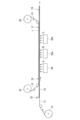
- FIGS. 1A to 1C are schematic diagrams illustrating an example of a method for producing a pressure-sensitive adhesive sheet of the present invention.
- 1A to 1C are schematic diagrams illustrating an example of a method for producing a pressure-sensitive adhesive sheet of the present invention.
- 1A to 1C are schematic diagrams illustrating an example of a method for producing a pressure-sensitive adhesive sheet of the present invention.
- FIG. 2 is a schematic diagram for explaining an example of a method for producing an optical film with a pressure-sensitive adhesive sheet of the present invention.
- FIG. 2 is a schematic diagram for explaining an example of a method for producing an optical film with a pressure-sensitive adhesive sheet of the present invention.
- FIG. 2 is a schematic diagram for explaining an example of a method for producing an optical film with a pressure-sensitive adhesive sheet of the present invention.
- a method for producing a pressure-sensitive adhesive sheet includes the steps of: A step A of irradiating a coating layer containing a photocurable composition with light A from a light emitting diode; a step B of irradiating the coating layer with light B after the step A; Including, The light A has a peak wavelength of 325 nm to 350 nm, An illuminance LB of the light B irradiated to the coating layer is greater than an illuminance LA of the light A irradiated to the coating layer.
- the peak wavelength is 340 ⁇ 10 nm.
- step A the light A is irradiated onto a laminate including a base sheet, the coating layer, and a release liner in this order.
- the illuminance LA is 2.0 to 30 mW/cm 2 .
- the ratio of the illuminance LB to the illuminance LA is 1.2 to 10.
- the light source of the light B is at least one selected from the group consisting of a light emitting diode, a metal halide lamp, and a black light source.
- the manufacturing method according to any one of the first to sixth aspects further includes, after the step B, a step C of irradiating the coating layer with light C, and the illuminance LC of the light C irradiated to the coating layer is greater than the illuminance LB.
- the photocurable composition contains a monomer group including a (meth)acrylic monomer and/or a partial polymer of the monomer group.
- the polymerization rate of the monomer group at the time when the step A is completed is 50% or more.
- the polymerization rate of the monomer group in the adhesive sheet is 95% or more.
- the photocurable composition contains a photopolymerization initiator, and the amount of the photopolymerization initiator is 1.0 part by weight or less per 100 parts by weight of the total of the monomer group and the partially polymerized product.
- the content of the solvent in the photocurable composition is 5% by weight or less.
- a method for producing an optical film with a pressure-sensitive adhesive sheet according to a thirteenth aspect of the present invention comprises the steps of: The method includes forming an optical film with a pressure-sensitive adhesive sheet by disposing an optical film on an exposed surface of the pressure-sensitive adhesive sheet formed by the manufacturing method according to any one of the first to twelfth aspects.
- the optical film includes at least one film selected from the group consisting of a polarizing film and a retardation film.
- a method for producing an image display device includes the steps of: The method includes bonding an optical film with a pressure-sensitive adhesive sheet formed by the manufacturing method according to the thirteenth or fourteenth aspect to an image display panel to form an image display device.
- the method for producing a pressure-sensitive adhesive sheet 1 of the present embodiment includes a step A of irradiating a coating layer 12 containing a photocurable composition with light A from a light-emitting diode (LED) 34, and a step B of irradiating the coating layer 12 with light B after the step A.
- the light A has a peak wavelength of 325 nm to 350 nm.
- the illuminance LB of the light B irradiated to the coating layer 12 is greater than the illuminance LA of the light A irradiated to the coating layer 12 in the step A.
- the manufacturing method of this embodiment by carrying out steps A and B, the polymerization rate of the monomer group in the produced adhesive sheet 1 is likely to increase. By using steps A and B, the adhesive sheet 1 can also be produced in a relatively short time. In this way, the manufacturing method of this embodiment is suitable for efficiently producing the adhesive sheet 1.
- a laminate (first laminate) 10 is prepared that includes a base sheet 11, a coating layer 12 containing a photocurable composition, and a release liner 13 in this order.
- Light A is irradiated to the first laminate 10 (step A).
- Step A is the first light irradiation step performed on the first laminate 10.
- step B light B is irradiated to the first laminate 10 (step B).
- the manufacturing method of this embodiment may further include, after step B, step C of irradiating light C onto the first laminate 10 (specifically, coating layer 12).
- the illuminance LC of light C irradiated onto the first laminate 10 (specifically, coating layer 12) is adjusted to a value greater than the illuminance LB.
- light may be irradiated onto the first laminate 10 (specifically, coating layer 12) with gradually increasing illuminance.
- the coating layer 12 hardens and the adhesive sheet 1 is formed.
- the formed adhesive sheet 1 is sandwiched between the base sheet 11 and the release liner 13 until the release liner 13 is peeled off, and forms part of the second laminate 17.
- a third laminate 15 including the base sheet 11 and the adhesive sheet 1 is obtained.
- the surface of the adhesive sheet 1 is exposed to the outside.
- step A irradiation with light A is typically performed from the side of the base sheet 11. At this time, light A penetrates the base sheet 11 to reach the coating layer 12 and initiates curing of the coating layer 12. However, irradiation with light A may also be performed from the side of the release liner 13, or from both the side of the release liner 13 and the side of the base sheet 11.
- the peak wavelength of light A irradiated to the first laminate 10 is 325 nm to 350 nm.
- the peak wavelength of light A is preferably 340 ⁇ 10 nm (330 nm to 350 nm), may be 340 ⁇ 5 nm (335 nm to 345 nm), may be 340 ⁇ 2 nm (338 nm to 342 nm), or may be 340 nm.
- the peak wavelength means the wavelength at which the intensity is at a maximum value in the spectrum showing the relationship between the wavelength and intensity of light A.
- Light A may further have a peak wavelength in a wavelength range other than 325 nm to 350 nm, but preferably does not have one.
- the illuminance LA of the light A irradiated to the first laminate 10 is, for example, 2.0 to 30 mW/cm 2.
- the coating layer 12 tends to be uniformly cured.
- the cleavage rate of the photopolymerization initiator contained in the photocurable composition can be appropriately adjusted, and the polymerization rate of the monomer group tends to increase.
- the illuminance LA of the light A is 30 mW/cm 2 or less, rapid heat generation of the coating layer 12 is suppressed, and the adhesive sheet 1 tends to be less prone to poor appearance.
- the sum of the illuminance LA of light A from the release liner 13 side and the illuminance LA of light A from the base sheet 11 side is adjusted to, for example, 2.0 to 30 mW/ cm2 .
- the illuminance LA of the light A is preferably 2.5 mW/cm 2 or more, 3.0 mW/cm 2 or more, 3.5 mW/cm 2 or more, 4.0 mW/cm 2 or more, 5.0 mW/cm 2 or more, 6.0 mW/cm 2 or more, 7.0 mW/cm 2 or more, 8.0 mW/cm 2 or more, or even 9.0 mW/cm 2 or more.
- the upper limit of the illuminance LA of the light A is, for example, 25 mW/cm 2 or less, 20 mW/cm 2 or less, 15 mW/cm 2 or less, or even 10 mW/cm 2 or less.
- the illuminance LA of the light A is preferably 6.0 to 10 mW/cm 2.
- the illuminance LA of the light A can be adjusted not only by controlling the LED 34 itself, but also by changing the distance between the LED 34 and the first laminate 10.
- the time for which light A is irradiated to the first laminate 10 is not particularly limited, and may be, for example, 10 to 500 seconds, or may be 30 seconds or more, 60 seconds or more, or even 100 seconds or more.
- the upper limit of the time for irradiating light A is, for example, 300 seconds or less. Irradiation of light A may be continuous or intermittent.
- the integrated light amount of light A on the first laminate 10 may be, for example, 25 mJ/cm 2 or more, 100 mJ/cm 2 or more, 300 mJ/cm 2 or more, 500 mJ/cm 2 or more, or even 800 mJ/cm 2 or more.
- the upper limit of the integrated light amount of light A is not particularly limited, and may be, for example, 10,000 mJ/cm 2 or less, 5,000 mJ/cm 2 or less, 3,000 mJ/cm 2 or less, or even 1,000 mJ/cm 2 or less.
- the integrated light amount of light A is preferably 500 to 1,000 mJ/cm 2 .
- the temperature of the coating layer 12 is maintained at, for example, 50°C or less, preferably 10°C to 30°C. In this case, the curing speed of the coating layer 12 is appropriately adjusted, and the number average molecular weight and weight average molecular weight of the polymer contained in the adhesive sheet 1 tend to increase.
- the first laminate 10 (specifically, the coating layer 12) may be irradiated with light A in an atmosphere with a reduced oxygen concentration compared to the air (oxygen concentration 20.9 vol%).
- the curing of the coating layer 12 is less likely to be inhibited by oxygen, and the number-average molecular weight and weight-average molecular weight of the polymer contained in the adhesive sheet 1 tend to increase.
- the irradiation with light A may be performed in an atmosphere with an oxygen concentration of 20 vol% or less, 10 vol% or less, 1 vol% or less, 1000 volppm or less, or even 500 volppm or less.
- the irradiation with light A may be performed in an atmosphere that is substantially free of oxygen.
- the atmosphere with a reduced oxygen concentration contains, for example, an inert gas such as argon or nitrogen, and is typically an inert gas atmosphere.
- process A light A from LED 34 is used. This tends to result in a higher polymerization rate of the monomer group in the formed adhesive sheet 1 compared to, for example, when a black light source is used in process A, or when an LED that emits light with a peak wavelength of approximately 365 nm is used in process A. Furthermore, by using light A from LED 34 in process A, the amount of remaining photopolymerization initiator in the formed adhesive sheet 1 also tends to decrease.
- LEDs tend to have a longer light source life than black light sources, as well as being easier to adjust the illuminance. LEDs are also superior in terms of reducing the environmental impact compared to black light sources that use mercury. Furthermore, according to the inventors' studies, LEDs that emit light A with a peak wavelength of 325 nm to 350 nm tend to generate less heat and to be easier to control the temperature of the coating layer 12 than LEDs that emit light with a peak wavelength of about 365 nm. Light 14 with a peak wavelength of 325 nm to 350 nm also tends to be more compatible with the absorption wavelength of the photopolymerization initiator than light with a peak wavelength of about 365 nm. In addition, as far as the inventors know, there have been no reported examples of adhesive sheets being made using LEDs that emit light with a peak wavelength of 325 nm to 350 nm.
- step B irradiation with light B is typically performed from the side of the base sheet 11. At this time, light B passes through the base sheet 11 to reach the coating layer 12 and promotes the curing of the coating layer 12. However, irradiation with light B may be performed from the side of the release liner 13, or from both the side of the release liner 13 and the side of the base sheet 11.
- Light B is, for example, visible light or ultraviolet light having a wavelength shorter than 450 nm.
- Light B may be light in which short-wavelength light of 300 nm or less has been cut using a filter or the like.
- Examples of the light source 35a for light B include LEDs, low-pressure mercury lamps, medium-pressure mercury lamps, high-pressure mercury lamps, extra-high-pressure mercury lamps, metal halide lamps, xenon lamps, microwave-excited mercury lamps, black light sources, chemical lamps, germicidal lamps, low-pressure discharge mercury lamps, and excimer lasers. It is preferable that the light source 35a for light B is at least one selected from the group consisting of LEDs, metal halide lamps, and black light sources.
- the light source 35a may be an LED that irradiates light with a peak wavelength of 300 to 450 nm, or an LED that irradiates light with a peak wavelength of 325 nm to 350 nm.
- An example of this LED is the above-mentioned LED 34.
- the light source 35a may be an LED that irradiates light with a peak wavelength of 365 ⁇ 10 nm.
- the illuminance LB of light B irradiated to the first laminate 10 is greater than the illuminance LA of light A. This allows the coating layer 12 to be cured in a shorter time than when only step A is performed.
- the illuminance LB of light B is, for example, 5.0 to 80 mW/cm 2.
- the sum of the illuminance LB of light B from the release liner 13 side and the illuminance LB of light B from the base sheet 11 side is adjusted to, for example, 5.0 to 80 mW/cm 2 .
- the illuminance LB of the light B is preferably 8.0 mW/cm 2 or more, and may be 10 mW/cm 2 or more, 13 mW/cm 2 or more, 15 mW/cm 2 or more, 18 mW/cm 2 or more, or even 20 mW/cm 2 or more.
- the upper limit of the illuminance LB of the light B is, for example, 70 mW/cm 2 or less, and may be 60 mW/cm 2 or less, 50 mW/cm 2 or less, 45 mW/cm 2 or less, or even 40 mW/cm 2 or less.
- the illuminance LB of the light B can be adjusted not only by controlling the light source 35a itself, but also by changing the distance between the light source 35a and the first laminate 10.
- the ratio LB/LA of the illuminance LB of light B to the illuminance LA of light A is not particularly limited and may be, for example, 1.2 to 10, and may be 8.0 or less, 6.0 or less, 5.0 or less, 4.0 or less, 3.0 or less, or even 2.5 or less.
- the lower limit of the ratio LB/LA may be 1.5 or more, 1.8 or more, or even 2.0 or more.
- the time for which light B is irradiated to the first laminate 10 is not particularly limited, and may be, for example, 10 to 500 seconds, or may be 30 seconds or more, 60 seconds or more, or even 100 seconds or more.
- the upper limit of the time for irradiating light B is, for example, 300 seconds or less. Irradiation of light B may be continuous or intermittent.
- the integrated light amount of light B on the first laminate 10 is, for example, 50 mJ/cm 2 or more, and may be 100 mJ/cm 2 or more, 300 mJ/cm 2 or more, 500 mJ/cm 2 or more, 800 mJ/cm 2 or more, or even 1000 mJ/cm 2 or more.
- the upper limit of the integrated light amount of light B is not particularly limited, and may be, for example, 10000 mJ/cm 2 or less, 5000 mJ/cm 2 or less, or even 3000 mJ/cm 2 or less.
- the temperature of the coating layer 12 and the surrounding atmosphere while the first laminate 10 (specifically the coating layer 12) is irradiated with light B may be the conditions described above for step A. It is preferable that step B be performed within 30 seconds after the end of step A, and it is particularly preferable that step B be performed immediately after the end of step A.
- Step C In step C, irradiation with light C is typically performed from the side of the base sheet 11. At this time, light C penetrates the base sheet 11 to reach the coating layer 12 and promotes the curing of the coating layer 12. However, irradiation with light C may be performed from the side of the release liner 13, or from both the side of the release liner 13 and the side of the base sheet 11.
- Light C is, for example, visible light or ultraviolet light having a wavelength shorter than 450 nm.
- Light C may be light in which short-wavelength light of 300 nm or less has been cut using a filter or the like.
- Examples of light sources 35b for light C include those described above for light source 35a for light B, and in detail, include LEDs, low-pressure mercury lamps, medium-pressure mercury lamps, high-pressure mercury lamps, extra-high-pressure mercury lamps, metal halide lamps, xenon lamps, microwave-excited mercury lamps, black light sources, chemical lamps, germicidal lamps, low-pressure discharge mercury lamps, and excimer lasers.
- light source 35b for light C is at least one selected from the group consisting of LEDs, metal halide lamps, and black light sources.
- light source 35b may be an LED that irradiates light with a peak wavelength of 300 to 450 nm, or an LED that irradiates light with a peak wavelength of 325 to 350 nm.
- An example of this LED is the above-mentioned LED 34.
- light source 35b may be an LED that emits light with a peak wavelength of 365 ⁇ 10 nm.
- the illuminance LC of light C irradiated to the first laminate 10 is greater than the illuminance LB of light B.
- the coating layer 12 can be cured in a shorter time.
- the illuminance LC of light C is, for example, 10 to 100 mW/cm 2.
- the sum of the illuminance LC of light C from the release liner 13 side and the illuminance LC of light C from the base sheet 11 side is adjusted to, for example, 10 to 100 mW/cm 2 .
- the illuminance LC of the light C is preferably 13 mW/cm 2 or more, and may be 15 mW/cm 2 or more, 20 mW/cm 2 or more, or even 30 mW/cm 2 or more.
- the upper limit of the illuminance LC of the light C is, for example, 80 mW/cm 2 or less, and may be 70 mW/cm 2 or less, 60 mW/cm 2 or less, 50 mW/cm 2 or less, or even 40 mW/cm 2 or less.
- the illuminance LC of the light C can be adjusted not only by controlling the light source 35b itself, but also by changing the distance between the light source 35b and the first laminate 10.
- the ratio LC/LB of the illuminance LC of light C to the illuminance LB of light B is not particularly limited and may be, for example, 1.2 to 10, and may be 8.0 or less, 6.0 or less, 5.0 or less, 4.0 or less, 3.0 or less, or even 2.5 or less.
- the lower limit of the ratio LC/LB may be 1.5 or more, 1.8 or more, or even 2.0 or more.
- the time for which the first laminate 10 (specifically the coating layer 12) is irradiated with light C is not particularly limited, and may be, for example, 10 to 500 seconds, or may be 30 seconds or more, 60 seconds or more, or even 100 seconds or more.
- the upper limit of the time for irradiating light C is, for example, 300 seconds or less. Irradiation with light C may be continuous or intermittent.
- the integrated light amount of the light C on the first laminate 10 is, for example, 100 mJ/ cm2 or more, and may be 300 mJ/cm2 or more , 500 mJ/ cm2 or more, 800 mJ/ cm2 or more, or even 1000 mJ/ cm2 or more.
- the upper limit of the integrated light amount of the light C is not particularly limited, and may be, for example, 10000 mJ/ cm2 or less, 5000 mJ/cm2 or less, or even 3000 mJ/cm2 or less .
- the temperature of the coating layer 12 and the surrounding atmosphere while the first laminate 10 (specifically the coating layer 12) is irradiated with light C may be the conditions described above for step A. It is preferable that step C be performed within 30 seconds after the end of step B, and it is particularly preferable that step C be performed immediately after the end of step B.
- the total time (total irradiation time) for irradiating the first laminate 10 (specifically, the coating layer 12) with light is not particularly limited, and may be, for example, 20 seconds to 1000 seconds, or may be 60 seconds or more, 100 seconds or more, 150 seconds or more, 200 seconds or more, or even 250 seconds or more.
- the upper limit of the total irradiation time is, for example, 800 seconds or less, and may be 600 seconds or less, 500 seconds or less, or even 400 seconds or less.
- the manufacturing method of this embodiment may further include, after steps A to B (and in some cases steps A to C), a heating step of heating the adhesive sheet 1.
- the heating step is performed on a third laminate 15 including the base sheet 11 and the adhesive sheet 1. The heating step promotes drying and curing of the adhesive sheet 1, and tends to further reduce the residual monomer contained in the adhesive sheet 1.
- the conditions for the heating process are not particularly limited and can be adjusted as appropriate.
- the temperature for the heating process is preferably 40 to 200°C, more preferably 50 to 180°C, and even more preferably 70 to 170°C.
- the time for the heating process is, for example, 5 seconds to 20 minutes, preferably 5 seconds to 10 minutes, and more preferably 10 seconds to 5 minutes.
- the photocurable composition is a pressure-sensitive adhesive composition that forms the pressure-sensitive adhesive sheet 1 from the coating layer 12 by irradiation with light A or the like.
- the photocurable composition includes, for example, a monomer group containing a (meth)acrylic monomer and/or a partial polymer of the monomer group.
- the content of the (meth)acrylic component in the photocurable composition, i.e., the (meth)acrylic monomer and its partial polymer may be 50% by weight or more, 60% by weight or more, 70% by weight or more, or even 80% by weight or more.
- an acrylic pressure-sensitive adhesive sheet 1 containing a (meth)acrylic polymer and its crosslinked product as the main components can be formed.
- the photocurable composition is not limited to the above example.
- (meth)acrylic means acrylic and methacrylic.
- (Meth)acrylate means acrylate and methacrylate.
- An example of a (meth)acrylic monomer is a (meth)acrylic acid alkyl ester having an alkyl group having 1 to 20 carbon atoms on the side chain.
- the number of carbon atoms in the alkyl group may be 7 or less, 6 or less, 5 or less, or even 4 or less.
- the alkyl group may be linear or branched.
- Examples of (meth)acrylic acid alkyl esters are methyl (meth)acrylate, ethyl (meth)acrylate, propyl (meth)acrylate, isopropyl (meth)acrylate, n-butyl (meth)acrylate, s-butyl (meth)acrylate, t-butyl (meth)acrylate, isobutyl (meth)acrylate, n-pentyl (meth)acrylate, isopentyl (meth)acrylate, n-hexyl (meth)acrylate, isohexyl (meth)acrylate, isoheptyl (meth)acrylate, 2-ethylhexyl (meth)acrylate, and 2-ethylhexyl (meth)acrylate.
- the (meth)acrylic acid alkyl ester may be n-butyl (meth)acrylate.
- the content of (meth)acrylic acid alkyl ester in the monomer group is, for example, 40% by weight or more, and may be 50% by weight or more, 60% by weight or more, 70% by weight or more, 80% by weight or more, 85% by weight or more, 90% by weight or more, or even 95% by weight or more.
- the weight of the partially polymerized product is converted into the weight of each monomer before polymerization.
- the monomer group may contain a carboxyl group-containing monomer.
- the carboxyl group-containing monomer may be a (meth)acrylic monomer, in other words, the (meth)acrylic monomer may contain a carboxyl group-containing monomer.
- Examples of the carboxyl group-containing monomer are (meth)acrylic acid, carboxyethyl (meth)acrylate, carboxypentyl (meth)acrylate, itaconic acid, maleic acid, fumaric acid, and crotonic acid.
- the content of the carboxyl group-containing monomer in the monomer group may be, for example, 10% by weight or less, 9% by weight or less, 8% by weight or less, 7% by weight or less, 6% by weight or less, 5.5% by weight or less, or even 5% by weight or less.
- the lower limit of the content may be, for example, 0.1% by weight or more, 0.5% by weight or more, or even 1% by weight or more.
- the monomer group may not contain a carboxyl group-containing monomer.
- the monomer group may contain a hydroxy group-containing monomer.
- the hydroxy group-containing monomer may be a (meth)acrylic monomer, in other words, the (meth)acrylic monomer may contain a hydroxy group-containing monomer.
- the hydroxy group-containing monomer may contribute to improving the cohesive strength of the adhesive sheet.
- hydroxy group-containing monomer examples include 2-hydroxyethyl (meth)acrylate, 2-hydroxypropyl (meth)acrylate, 4-hydroxybutyl (meth)acrylate, 6-hydroxyhexyl (meth)acrylate, 8-hydroxyoctyl (meth)acrylate, 10-hydroxydecyl (meth)acrylate, 12-hydroxylauryl (meth)acrylate, and (4-hydroxymethylcyclohexyl)-methyl acrylate.
- the hydroxy group-containing monomer is preferably 2-hydroxyethyl (meth)acrylate or 4-hydroxybutyl (meth)acrylate.
- the content of the hydroxyl group-containing monomer in the monomer group is, for example, 10% by weight or less, and may be 5% by weight or less, 4% by weight or less, 3% by weight or less, 2% by weight or less, 1% by weight or less, 0.8% by weight or less, 0.5% by weight or less, 0.3% by weight or less, 0.2% by weight or less, or even 0.1% by weight or less.
- the lower limit of the content may be, for example, 0.01% by weight or more, 0.03% by weight or more, or even 0.05% by weight or more.
- the monomer group may not contain a hydroxyl group-containing monomer.
- the monomer group may include a nitrogen atom-containing monomer.
- a nitrogen atom-containing monomer means a monomer that has at least one nitrogen atom in the molecule (per molecule).
- N-vinyl cyclic amide, (meth)acrylamide, etc. are preferred.
- the nitrogen atom-containing monomer may be used alone or in combination of two or more kinds.
- the N-vinyl cyclic amide is preferably represented by the following formula (1).
- R 1 is a divalent organic group, preferably a divalent saturated or unsaturated hydrocarbon group, and more preferably a divalent saturated hydrocarbon group (e.g., an alkylene group having 3 to 5 carbon atoms). Note that formula (1) shows that N and R 1 are directly bonded to each other via a single bond to form a ring structure.
- N-vinyl-2-pyrrolidone N-vinyl-2-piperidone, N-vinyl-2-caprolactam, N-vinyl-3-morpholinone, N-vinyl-1,3-oxazin-2-one, N-vinyl-3,5-morpholinedione, etc. are preferred, more preferably N-vinyl-2-pyrrolidone, N-vinyl-2-caprolactam, and even more preferably N-vinyl-2-pyrrolidone.
- Examples of (meth)acrylamides include (meth)acrylamide, N-alkyl (meth)acrylamide, and N,N-dialkyl (meth)acrylamide.
- Examples of N-alkyl (meth)acrylamide include N-ethyl (meth)acrylamide, N-isopropyl (meth)acrylamide, N-n-butyl (meth)acrylamide, and N-octyl acrylamide.
- Examples of N-alkyl (meth)acrylamides include (meth)acrylamides having an amino group, such as dimethylaminoethyl (meth)acrylamide, diethylaminoethyl (meth)acrylamide, and dimethylaminopropyl (meth)acrylamide.
- N,N-dialkyl(meth)acrylamides include N,N-dimethyl(meth)acrylamide, N,N-diethyl(meth)acrylamide, N,N-dipropyl(meth)acrylamide, N,N-diisopropyl(meth)acrylamide, N,N-di(n-butyl)(meth)acrylamide, and N,N-di(t-butyl)(meth)acrylamide.
- (Meth)acrylamides also include, for example, various N-hydroxyalkyl(meth)acrylamides.
- N-hydroxyalkyl(meth)acrylamides include N-methylol(meth)acrylamide, N-(2-hydroxyethyl)(meth)acrylamide, N-(2-hydroxypropyl)(meth)acrylamide, N-(1-hydroxypropyl)(meth)acrylamide, N-(3-hydroxypropyl)(meth)acrylamide, N-(2-hydroxybutyl)(meth)acrylamide, N-(3-hydroxybutyl)(meth)acrylamide, N-(4-hydroxybutyl)(meth)acrylamide, and N-methyl-N-2-hydroxyethyl(meth)acrylamide.
- (Meth)acrylamides also include, for example, various N-alkoxyalkyl(meth)acrylamides.
- N-alkoxyalkyl(meth)acrylamides include N-methoxymethyl(meth)acrylamide and N-butoxymethyl(meth)acrylamide.
- Nitrogen atom-containing monomers other than N-vinyl cyclic amide and (meth)acrylamide include, for example, amino group-containing monomers such as aminoethyl (meth)acrylate, dimethylaminoethyl (meth)acrylate, dimethylaminopropyl (meth)acrylate, and t-butylaminoethyl (meth)acrylate; cyano group-containing monomers such as acrylonitrile and methacrylonitrile; (meth)acryloylmorpholine, N-vinylpiperazine, N-vinylpyrrole, N-vinylimidazole, N-vinylpyrazine, N-vinylmorpholine, N-vinylpyrazole, vinylpyridine, vinylpyrimidine, vinyloxazole, vinylisoxazole, vinylthiazole, vinylisothiazole, vinylpyridazine, (meth)acryloylpyrrolidone, (meth)
- the content of the nitrogen atom-containing monomer in the monomer group may be, for example, 40% by weight or less, 35% by weight or less, or even 30% by weight or less.
- the lower limit of the content may be, for example, 5% by weight or more, 7% by weight or more, or even 10% by weight or more.
- the monomer group may not contain any nitrogen atom-containing monomer.
- each of the above-mentioned monomers may be contained as a partial polymer.
- the partial polymer may be either a homopolymer or a copolymer.
- the partial polymer may contribute to the stable formation of the coating layer 12 by appropriately increasing the viscosity of the photocurable composition.
- the photocurable composition usually contains a photopolymerization initiator.
- a photopolymerization initiator is a photoradical generator that generates radicals by the above-mentioned light A.
- the photopolymerization initiator has an absorption coefficient for light with a wavelength of 340 nm of, for example, 0.1 L/(g cm) or more, and may be 0.5 L/(g cm) or more, 1.0 L/(g cm) or more, 3.0 L/(g cm) or more, or even 5.0 L/(g cm) or more. There is no particular upper limit to this absorption coefficient, and it is, for example, 50 L/(g cm) or less.
- the absorption coefficient of the photopolymerization initiator is a calculated value from the absorbance of a 0.01 mg/mL methanol solution measured with a visible-ultraviolet spectrophotometer using a quartz cell with an optical path length of 1 cm.
- photopolymerization initiators include benzoin ethers such as benzoin methyl ether, benzoin isopropyl ether, and benzil dimethyl ketal; substituted benzoin ethers such as anisole methyl ether; substituted acetophenones such as 2,2-diethoxyacetophenone and 2,2-dimethoxy-2-phenylacetophenone; ⁇ -hydroxyalkylphenones such as 1-hydroxycyclohexyl-phenyl ketone, 2-hydroxy-2-methylpropiophenone, 2-hydroxy-4'-(2-hydroxyethoxy)-2-methylpropiophenone, and 2,2'-dihydroxy-2,2'-dimethyl-1,1'-[methylenebis(4,1-phenylene)]bis(propan-1-one); 2-methyl-2-hydroxypropiophenone substituted alpha-ketols such as 2-naphthalenesulfonyl chloride; aromatic sulfonyl chlorides such as 2-naphthalene
- thioxanthone compounds such as 2,4,6-trichloro-s-triazine, 2-phenyl-4,6-bis(trichloromethyl)-s-triazine, 2-(p-methoxyphenyl)-4,6-bis(trichloromethyl)-s-triazine, 2-(p-tolyl)-4,6-bis(trichloromethyl)-s-triazine, 2-piperonyl-4,6-bis(trichloromethyl)-s-triazine, 2,4-bis(trichloromethyl)-6-styryl-s-triazine, 2-(naphth-1-yl)-4,6-bis(trichloromethyl)-s-triazine, 2-(4-methoxy-naphth-1-yl)-4,6-bis(trichloromethyl)-s-triazine, 2,4-trichloromethyl-(piperonyl)-6-triazine, 2,
- the photocurable composition may contain one or more photopolymerization initiators.
- ⁇ -hydroxyalkylphenones tend to have high absorption of light with wavelengths of 325 nm to 350 nm, making them suitable for the manufacturing method of this embodiment.
- the amount of photopolymerization initiator in the photocurable composition is, for example, 20 parts by weight or less, and may be 10 parts by weight or less, 5.0 parts by weight or less, 3.0 parts by weight or less, 1.0 parts by weight or less, 0.5 parts by weight or less, or even 0.3 parts by weight or less, based on 100 parts by weight of the total of the monomer group and its partial polymer.
- the amount of photopolymerization initiator is 1.0 part by weight or less, the weight average molecular weight of the polymer contained in the adhesive sheet 1 tends to be sufficiently large.
- the lower limit of the amount of photopolymerization initiator is, for example, 0.02 parts by weight or more, and may be 0.05 parts by weight or more, based on 100 parts by weight of the total of the monomer group and its partial polymer.
- the photocurable composition may contain a crosslinking agent.
- a crosslinking agent is a polyfunctional monomer having two or more polymerizable functional groups in one molecule.
- the polyfunctional monomer may be a (meth)acrylic monomer.
- polyfunctional monomers examples include (poly)ethylene glycol di(meth)acrylate, (poly)propylene glycol di(meth)acrylate, neopentyl glycol di(meth)acrylate, pentaerythritol di(meth)acrylate, pentaerythritol tri(meth)acrylate, dipentaerythritol hexa(meth)acrylate, 1,2-ethylene glycol di(meth)acrylate, 1,6-hexanediol di(meth)acrylate, 1,9-nonanediol diacrylate ( Polyfunctional acrylates (such as ester compounds of polyhydric alcohols and (meth)acrylic acid) such as 1,12-dodecanediol di(meth)acrylate, trimethylolpropane tri(meth)acrylate, and tetramethylolmethane tri(meth)acrylate; allyl (meth)acrylate, vinyl (meth)acryl
- the polyfunctional monomer is preferably a polyfunctional acrylate, and more preferably 1,9-nonanediol diacrylate, trimethylolpropane tri(meth)acrylate, hexanediol di(meth)acrylate, and dipentaerythritol hexa(meth)acrylate.
- the amount of the crosslinking agent to be blended varies depending on the molecular weight, the number of functional groups, etc., but may be, for example, 5 parts by weight or less, 3 parts by weight or less, 2 parts by weight or less, 1 part by weight or less, 0.5 parts by weight or less, or even 0.3 parts by weight or less, relative to 100 parts by weight of the total of the monomer group and its partial polymers.
- the lower limit of the blending amount is, for example, 0.01 parts by weight or more, and may even be 0.05 parts by weight or more.
- the photocurable composition may contain additives other than those mentioned above.
- additives include chain transfer agents, silane coupling agents, viscosity modifiers, tackifiers, plasticizers, softeners, antioxidants, fillers, colorants, antioxidants, surfactants, antistatic agents, and ultraviolet absorbers.
- the content of the solvent in the photocurable composition is, for example, 5% by weight or less, and may be 4% by weight or less, 3% by weight or less, 2% by weight or less, 1% by weight or less, or even 0.5% by weight or less.
- the photocurable composition may be substantially free of solvent. "Substantially free of solvent” means that solvents derived from additives, etc. are permitted at a content of, for example, 0.1% by weight or less, preferably 0.05% by weight or less, and more preferably 0.01% by weight or less.
- the viscosity of the photocurable composition is preferably 1 to 100 poise. Photocurable compositions having a viscosity in the above range are particularly suitable for forming the coating layer 12.
- liner substrate An example of the substrate of the release liner 13 (hereinafter, “liner substrate”) is a resin film.
- resins that can be contained in the liner substrate are polyesters such as polyethylene terephthalate and polyethylene naphthalate, acetate resins, polyethersulfone, polycarbonate, polyamide, polyimide, polyolefin, (meth)acrylic resins, polyvinyl chloride, polyvinylidene chloride, polystyrene, polyvinyl alcohol, polyarylate, and polyphenylene sulfide.
- the resin is preferably a polyester such as polyethylene terephthalate.
- the release liner 13 may be transparent to light A.
- the spectral transmittance of the release liner 13 for light with a wavelength of 340 nm may be, for example, 60% or more, 70% or more, or even 80% or more.
- the upper limit of the spectral transmittance is not particularly limited, and may be, for example, 95% or less, or may be 90% or less.
- the spectral transmittance for light with a wavelength of 340 nm can be determined, for example, by measuring the total light transmittance spectrum in the wavelength range of 300 to 2000 nm for the release liner 13 using a commercially available spectrophotometer, and determining it from the spectrum obtained.
- the thickness of the release liner 13 is, for example, 10 to 200 ⁇ m, and may be 25 to 150 ⁇ m.
- the release liner 13 may have layers other than the liner substrate.
- the release liner 13 may have a release layer.
- the release liner 13 may have, for example, a liner substrate and a release layer formed on one side of the liner substrate. This release liner 13 can be used so that the release layer is on the coating layer 12 side.
- the release layer is typically a cured layer of a release agent composition containing a release agent.
- Various types of release agents can be used, such as silicone-based release agents, fluorine-based release agents, long-chain alkyl-based release agents, fatty acid amide-based release agents, and silica powder.
- the release liner 13 may be provided with a cured layer of a release agent composition containing a silicone-based release agent as the main component (hereinafter, "silicone release layer").
- silicone release layer is particularly suitable for achieving both adhesion to the adhesive sheet 1 and releasability.
- the main component means the component with the largest content.
- the silicone-based release agent is, for example, a variety of curable silicone materials such as addition reaction type, condensation reaction type, ultraviolet curable type, electron beam curable type, and solventless type, with addition reaction curable silicone materials being preferred.
- Addition reaction curable silicone materials are particularly suitable for forming a release layer that is compatible with adhesion to the adhesive sheet 1 and releasability.
- the curable silicone material may be a silicone modified resin in which reactive silicone is introduced into an organic resin such as urethane, epoxy, or alkyd resin by graft polymerization or the like.
- addition reaction curing silicone material is a polyorganosiloxane having a vinyl group or an alkenyl group in the molecule.
- the addition reaction curing silicone material may not have a hydrosilyl group.
- alkenyl group are 3-butenyl, 4-pentenyl, 5-hexenyl, 6-heptenyl, 7-octenyl, 8-nonenyl, 9-decenyl, 10-undecenyl, and 11-dodecenyl.
- polyorganosiloxane examples include polyalkylalkylsiloxanes such as polydimethylsiloxane, polydiethylsiloxane, and polymethylethylsiloxane, polyalkylarylsiloxane, and copolymers of multiple types of Si atom-containing monomers such as poly(dimethylsiloxane-diethylsiloxane).
- the polyorganosiloxane is preferably polydimethylsiloxane.
- a release agent composition containing a silicone-based release agent as a main component usually contains a crosslinking agent.
- a crosslinking agent is a polyorganosiloxane having a hydrosilyl group.
- the crosslinking agent may have two or more hydrosilyl groups in one molecule.
- the silicone release agent composition may contain a curing catalyst.
- a curing catalyst is a platinum-based catalyst.
- the platinum-based catalyst are chloroplatinic acid, platinum olefin complexes, and chloroplatinic acid olefin complexes.
- the amount of the platinum-based catalyst used is, for example, 10 to 1000 ppm (by weight, platinum equivalent) based on the total solid content of the composition.
- the silicone release agent composition may contain additives.
- additives are release control agents and adhesion promoters.
- release control agents are unreactive silicone resins, and more specific examples are organosiloxanes such as octamethylcyclotetrasiloxane, and MQ resins.
- the amount of the release control agent and adhesion promoter used is, for example, 1 to 30% by weight in total based on the total solid content of the composition.
- Further examples of additives are fillers, antistatic agents, antioxidants, UV absorbers, plasticizers, and colorants.
- the amount of the further additives used is, for example, 10% by weight or less in total based on the total solid content of the composition.
- the silicone release agent composition may contain an organic solvent.
- organic solvents are hydrocarbon solvents such as cyclohexane, n-hexane, and n-heptane; aromatic solvents such as toluene and xylene; ester solvents such as ethyl acetate and methyl acetate; ketone solvents such as acetone and methyl ethyl ketone; and alcohol solvents such as methanol, ethanol, and butanol. Two or more types of organic solvents may be contained.
- the amount of organic solvent used is preferably 80 to 99.9% by weight of the silicone release agent composition.
- the release layer can be formed, for example, by heating and drying a coating film containing the release agent composition formed on a liner substrate.
- Various coating methods can be used to apply the release agent composition, such as roll coating, kiss roll coating, gravure coating, reverse coating, roll brushing, spray coating, dip roll coating, bar coating, knife coating, air knife coating, curtain coating, lip coating, and die coating.
- hot air drying can be used to heat and dry.
- the heating temperature and time vary depending on the heat resistance of the liner substrate, but are usually 80 to 150°C and about 10 seconds to 10 minutes. If necessary, irradiation with active energy rays such as ultraviolet rays may be used in combination.
- the thickness of the release layer is, for example, 10 to 300 nm.
- the upper limit of the thickness may be 200 nm or less, 150 nm or less, 120 nm or less, 110 nm or less, 100 nm or less, less than 100 nm, 90 nm or less, 80 nm or less, 70 nm or less, less than 70 nm, or even 65 nm or less.
- the lower limit of the thickness may be 15 nm or more, 20 nm or more, 25 nm or more, 30 nm or more, 35 nm or more, 40 nm or more, 45 nm or more, or even 50 nm or more.
- the release liner 13 may be in the form of a sheet or a long piece.
- Base sheet 11 An example of the base sheet 11 is a resin film. Examples of the resin contained in the base sheet 11 are the same as the examples of the resin that can be contained in the liner base material.
- the base sheet 11 preferably has excellent transmittance to light A.
- the spectral transmittance of the base sheet 11 for light with a wavelength of 340 nm is, for example, 60% or more, and may be 70% or more, or even 80% or more. The higher the spectral transmittance, the more efficiently the coating layer 12 can be cured by light A. Furthermore, the base sheet 11 can be prevented from absorbing light A and generating heat.
- the upper limit of the spectral transmittance is not particularly limited, and may be, for example, 95% or less, or may be 90% or less.
- the spectral transmittance for light with a wavelength of 340 nm can be determined by the method described above for the release liner 13.
- the thickness of the base sheet 11 is, for example, 10 to 200 ⁇ m, and may be 25 to 150 ⁇ m.
- the base sheet 11 may have a release layer on the surface on the side of the coating layer 12.
- Examples of the release layer that the base sheet 11 may have and the manufacturing method thereof are the same as the examples of the release layer that the release liner 13 may have and the manufacturing method thereof.
- Both the release liner 13 and the base sheet 11 may have a release layer.
- both release layers may be formed from a release agent composition containing the same release agent as a main component.
- the thicknesses of both release layers may be different; for example, the release layer provided on the base sheet 11 may be thicker.
- a sheet that has a greater peel strength with respect to the adhesive sheet 1 than the release liner 13 can usually be selected.
- the base sheet 11 may be in the form of a sheet or a long piece.
- the first laminate 10 may include an additional layer other than the base sheet 11, the coating layer 12, and the release liner 13.
- the additional layer may be disposed on the side of the base sheet 11 and/or the release liner 13 opposite to the side of the coating layer 12. It is preferable that the coating layer 12 is in contact with the base sheet 11 and the release liner 13.
- the first laminate 10 can be formed, for example, by forming a coating layer 12 on a base sheet 11 (or a release liner 13) and then placing the release liner 13 (or base sheet 11) on the formed coating layer 12.
- the first laminate 10 may also be formed by applying a photocurable composition in a poured manner into the space between the base sheet 11 and the release liner 13, which are held at a predetermined distance so that their main surfaces face each other.
- a variety of coating methods can be used to form the coating layer 12, including roll coating, kiss roll coating, gravure coating, reverse coating, roll brushing, spray coating, dip roll coating, bar coating, knife coating, air knife coating, curtain coating, lip coating, and die coating.
- the thickness of the coating layer 12 can be adjusted according to the desired thickness of the adhesive sheet 1, and may be, for example, 2 mm or less, 1 mm or less, 2 to 300 ⁇ m, 2 to 200 ⁇ m, 2 to 150 ⁇ m, 2 to 100 ⁇ m, 2 to 70 ⁇ m, 2 to 50 ⁇ m, 5 to 40 ⁇ m, 10 to 30 ⁇ m, 10 to 25 ⁇ m, or even 10 to 20 ⁇ m.
- the first laminate 10 may include a long base sheet 11, a long coating layer 12, and a long release liner 13, in other words, may be long.
- the long first laminate 10 can be obtained, for example, by forming the coating layer 12 between the base sheet 11 and the release liner 13 while transporting them, which are unwound from a roll.
- the adhesive sheet 1 produced by the manufacturing method of this embodiment tends to have a small amount of remaining photopolymerization initiator.
- the adhesive sheet 1 with a small amount of remaining photopolymerization initiator tends to be suppressed from yellowing or foaming in a high temperature environment.
- the content of the photopolymerization initiator in the adhesive sheet 1 is, for example, 500 wtppm or less, and may be 300 wtppm or less, 200 wtppm or less, 150 wtppm or less, 120 wtppm or less, 100 wtppm or less, 80 wtppm or less, 50 wtppm or less, or even 30 wtppm or less.
- the adhesive sheet 1 may not substantially contain a photopolymerization initiator.
- the polymerization rate of the monomer group tends to be high and the amount of remaining monomer group tends to be small.
- An adhesive sheet 1 with a small amount of remaining monomer group not only contributes to improving productivity, but also tends to suppress odor.
- This adhesive sheet 1 also has the advantage of being easy to handle and transport.
- the polymerization rate of the monomer group in the adhesive sheet 1 is preferably 80% or more, and may be 85% or more, 90% or more, 95% or more, 97% or more, 98% or more, or even 99% or more.
- the polymerization rate of the monomer group at the end of step A is preferably 50% or more, and may be 60% or more, or even 70% or more.
- the upper limit of this polymerization rate is not particularly limited, and may be, for example, 90% or less, or 80% or less.
- the molecular weight of the polymer contained in the adhesive sheet 1 also tends to be large.
- the weight average molecular weight (Mw) of the polymer obtained by polymerization of the monomer group contained in the sample is, for example, 400,000 or more, 500,000 or more, 600,000 or more, 700,000 or more, 800,000 or more, 900,000 or more, or even 1 million or more. The larger this Mw is, the more likely peeling of the adhesive sheet 1 in a high temperature environment is suppressed.
- the upper limit of Mw is not particularly limited, and is, for example, 3 million or less.
- the number average molecular weight (Mn) of the above-mentioned polymer is, for example, 80,000 or more, and may be 100,000 or more, 150,000 or more, 180,000 or more, 200,000 or more, or even 250,000 or more.
- the upper limit of Mn is not particularly limited, and is, for example, 600,000 or less.
- the weight average molecular weight (Mw)/number average molecular weight (Mn), which indicates the molecular weight distribution, is, for example, 1.8 to 10, or may be 1.8 to 7, or even 1.8 to 5.
- the weight average molecular weight and number average molecular weight are measured by GPC (gel permeation chromatography) and calculated in terms of polystyrene.
- the gel fraction of the adhesive sheet 1 is, for example, 50% or more, and may be 75% or more, 80% or more, or even 85% or more.
- the thickness of the adhesive sheet 1 is, for example, 2 mm or less, and may be 1 mm or less, 2 to 300 ⁇ m, 2 to 200 ⁇ m, 2 to 150 ⁇ m, 2 to 100 ⁇ m, 2 to 70 ⁇ m, 2 to 50 ⁇ m, 5 to 40 ⁇ m, 10 to 30 ⁇ m, 10 to 25 ⁇ m, or even 10 to 20 ⁇ m.
- the adhesive sheet 1 produced by the manufacturing method of this embodiment is particularly suitable for applications requiring high light transmittance (e.g. optical applications). However, the adhesive sheet 1 can also be used for various applications other than optical applications.
- the adhesive sheet 1 may be used as a double-sided tape.
- a coating layer 12 of a photocurable composition is formed on one side of a long base sheet 11 unwound from a roll 31 by a coating device 32.
- a long release liner 13 unwound from a roll 33 is placed on the coating layer 12 to form a long first laminate 10.
- the first laminate 10 is irradiated with light A from an LED 34 in step A and with light B from a light source 35a in step B, and if necessary, with light C from a light source 35b in step C. This forms a long adhesive sheet 1.
- the release liner 13 is peeled off from a second laminate 17 including the adhesive sheet 1 and wound up on a roll 36.
- the above steps are performed while the base sheet 11 and the release liner 13 are being transported.
- the method of FIG. 2 is particularly suitable for mass production of adhesive sheets.
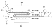
- a coating device 32 is used to coat a photocurable composition between a long substrate sheet 11 unwound from a roll 31 and a long release liner 13 unwound from a roll 33. This forms a coating layer 12 containing the photocurable composition, and a long first laminate 10 is obtained.
- the first laminate 10 is transported so as to pass between the pair of light sources 38a and 38b.
- the first laminate 10 is first transported through the first region 40A near the light source 38a.
- the first reversal mechanism (first transport roller 39a) is used to reverse the moving direction of the first laminate 10, and the first laminate 10 is moved in the opposite direction to the moving direction in the first region 40A. This causes the first laminate 10 to pass through the second region 40B, which is closer to the light source 38b than the first region 40A.
- the second reversal mechanism (second transport roller 39b) is used to further reverse the moving direction of the first laminate 10, and the first laminate 10 is moved in the same direction as the moving direction in the first region 40A. This causes the first laminate 10 to pass through the third region 40C near the light source 38b.
- Light source 38a is typically an LED that emits light L1 with a peak wavelength of 325 nm to 350 nm.
- light source 38b is typically an LED that emits light L2 with a peak wavelength of 325 nm to 350 nm.
- the above-mentioned LED 34 can be used as light sources 38a and 38b.
- the above-mentioned step A is performed in the first region 40A
- the above-mentioned step B is performed in the second region 40B
- the above-mentioned step C is performed in the third region 40C.
- the total value (illuminance LB) of the illuminance of the light L1 from the base sheet 11 side and the illuminance of the light L2 from the release liner 13 side in the second region 40B is adjusted to be larger than the total value (illuminance LA) of the illuminance of the light L1 from the release liner 13 side and the illuminance of the light L2 from the base sheet 11 side in the first region 40A.
- the total value (illuminance LC) of the illuminance of the light L1 from the release liner 13 side and the illuminance of the light L2 from the base sheet 11 side in the third region 40C is adjusted to be larger than the above-mentioned illuminance LB.
- the positions and outputs of the light sources 38a and 38b are adjusted so that the illuminances LA to LC satisfy the above relationship.
- the distance between light source 38a and first region 40A is adjusted to be greater than the distance between light source 38b and third region 40C.
- steps A to C are carried out, and a long adhesive sheet 1 is formed.
- the release liner 13 is peeled off from the second laminate 17 containing the adhesive sheet 1, and the sheet is wound up on a roll 36.
- the method of FIG. 3 allows steps A to C to be carried out in a small space, and is particularly suitable for mass production of adhesive sheets.
- the polymerization rate of the monomer group at the end of process A is 50% or more.
- the members constituting the first laminate 10 tend not to have poor appearance such as wrinkles, streaks, or lifting.
- FIG. 4 An example of a method for producing an optical film with a pressure-sensitive adhesive sheet according to the present embodiment will be described with reference to Fig. 4.
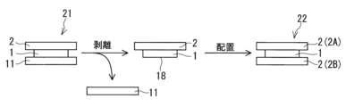
- an optical film 2 is disposed on an exposed surface 18 of a pressure-sensitive adhesive sheet 1 formed by peeling off a release liner 13 from a second laminate 17 produced by the above-mentioned method, to form an optical film with a pressure-sensitive adhesive sheet 21.
- a surface modification treatment may be applied to the exposed surface 18 of the pressure-sensitive adhesive sheet 1.
- the optical film 21 with adhesive sheet includes a base sheet 11, an adhesive sheet 1, and an optical film 2 in this order.
- the optical film 21 with adhesive sheet can be used as it is or after the base sheet 11 is peeled off, for example, as an optical laminate including the adhesive sheet 1 and the optical film 2 in an image display device or the like.
- the optical laminate may be attached to an object (e.g., an image forming panel) via the adhesive sheet 1.
- An additional member such as an optical film may be disposed on the exposed surface 18 formed by peeling off the base sheet 11 from the optical film 21 with adhesive sheet.
- an optical film 22 with adhesive sheet including an optical film 2A, an adhesive sheet 1, and an optical film 2B in this order can be formed (see FIG. 5).
- the optical films 2A and 2B may be the same or different from each other.
- the optical film 2 may be disposed directly or indirectly on the exposed surface 18.
- the optical film 2 may be disposed so as to be in contact with the exposed surface 18, or may be disposed with another layer sandwiched between the optical film 2 and the exposed surface 18.
- FIG. 6 another example of the method for manufacturing an optical film with an adhesive sheet according to this embodiment will be described.
- a long optical film 2 is placed on the exposed surface 18 of the adhesive sheet 1 in the third laminate 15 formed by the method of FIG. 2 to form a long optical film with an adhesive sheet 21.
- the optical film 2 is unwound from a roll 37 and placed on the exposed surface 18.
- the formation of the adhesive sheet 1 and the formation of the optical film with an adhesive sheet 21 may be carried out continuously.
- the method of FIG. 6 is particularly suitable for mass production of optical films with an adhesive sheet 21.
- the optical film 2 is, for example, a film including at least one selected from the group consisting of a polarizing film and a retardation film.
- the optical film 2 may be a laminated film including a polarizing film and/or a retardation film.
- the optical film 2 may include a glass film.
- the optical film 2 is not limited to the above examples.
- the polarizing film includes a polarizer.
- the polarizing film typically includes a polarizer and a protective film (transparent protective film).
- the protective film is, for example, disposed in contact with the main surface (the surface having the widest area) of the polarizer.
- the polarizer may be disposed between two protective films.
- the protective film may be disposed on at least one surface of the polarizer.
- the polarizer is not particularly limited, and examples include hydrophilic polymer films such as polyvinyl alcohol films, partially formalized polyvinyl alcohol films, and partially saponified ethylene-vinyl acetate copolymer films that have been uniaxially stretched after adsorbing dichroic substances such as iodine and dichroic dyes; and polyene-based oriented films such as dehydrated polyvinyl alcohol and dehydrochlorinated polyvinyl chloride.
- Polarizers are typically made of polyvinyl alcohol films (polyvinyl alcohol films include partially saponified ethylene-vinyl acetate copolymer films) and a dichroic substance such as iodine.
- the thickness of the polarizer is not particularly limited, and may be, for example, 80 ⁇ m or less, 50 ⁇ m or less, 30 ⁇ m or less, 25 ⁇ m or less, or even 20 ⁇ m or less.
- the lower limit of the polarizer thickness is not particularly limited, and may be, for example, 1 ⁇ m or more, 5 ⁇ m or more, 10 ⁇ m or more, or even 15 ⁇ m or more.
- a thin polarizer (for example, a thickness of 20 ⁇ m or less) suppresses dimensional changes and can contribute to improving the durability of the optical laminate, particularly its durability at high temperatures.
- thermoplastic resins excellent in transparency, mechanical strength, thermal stability, moisture blocking property, isotropy, etc.
- thermoplastic resins include cellulose resins such as triacetyl cellulose, polyester resins, polyethersulfone resins, polysulfone resins, polycarbonate resins, polyamide resins, polyimide resins, polyolefin resins, (meth)acrylic resins, cyclic polyolefin resins (norbornene resins), polyarylate resins, polystyrene resins, polyvinyl alcohol resins, and mixtures thereof.
- cellulose resins such as triacetyl cellulose, polyester resins, polyethersulfone resins, polysulfone resins, polycarbonate resins, polyamide resins, polyimide resins, polyolefin resins, (meth)acrylic resins, cyclic polyolefin resins (norbornene resins), polyarylate resins, polystyrene resins, poly
- the material of the protective film may be a thermosetting resin or an ultraviolet-curing resin such as a (meth)acrylic, urethane, acrylic urethane, epoxy, or silicone.
- a protective film made of a thermoplastic resin may be attached to one main surface of the polarizer via an adhesive
- a protective film made of a thermosetting resin or an ultraviolet-curing resin may be attached to the other main surface of the polarizer.
- the protective film may contain one or more types of additives. Examples of additives include ultraviolet absorbers, antioxidants, lubricants, plasticizers, release agents, color inhibitors, flame retardants, nucleating agents, antistatic agents, pigments, colorants, etc.
- the thickness of the protective film can be determined as appropriate, but is generally around 10 to 200 ⁇ m, taking into consideration strength, ease of handling, thinness, etc.
- the polarizer and protective film are usually adhered to each other via a water-based adhesive or the like.
- water-based adhesives include isocyanate-based adhesives, polyvinyl alcohol-based adhesives, gelatin-based adhesives, vinyl latex, water-based polyurethane, and water-based polyester.
- adhesives other than the above-mentioned adhesives include ultraviolet-curable adhesives and electron beam-curable adhesives.
- Electron beam-curable polarizing plate adhesives exhibit suitable adhesion to various protective films.
- the adhesive may contain a metal compound filler.
- polarizing films instead of a protective film, a phase difference film or the like can be formed on the polarizer.
- Another protective film can be further provided on the protective film, or a phase difference film or the like can be provided.
- the protective film may have a hard coat layer on the surface opposite to the surface attached to the polarizer, and may also be treated for the purposes of anti-reflection, anti-sticking, diffusion, anti-glare, etc.
- the polarizing film may be a circular polarizing film.
- the retardation film may be one obtained by stretching a polymer film or one obtained by aligning and fixing a liquid crystal material.
- the retardation film has birefringence, for example, in the in-plane and/or thickness direction.
- Retardation films include anti-reflection retardation films (see JP 2012-133303 A [0221], [0222], [0228]), viewing angle compensation retardation films (see JP 2012-133303 A [0225], [0226]), tilted orientation retardation films for viewing angle compensation (see JP 2012-133303 A [0227]), etc.
- the specific configuration of the retardation film such as the retardation value, arrangement angle, three-dimensional birefringence, single layer or multilayer, etc., is not particularly limited, and any known retardation film can be used.
- the thickness of the retardation film is preferably 20 ⁇ m or less, more preferably 10 ⁇ m or less, even more preferably 1 to 9 ⁇ m, and particularly preferably 3 to 8 ⁇ m.
- the retardation film may include, for example, a quarter-wave plate and/or a half-wave plate in which liquid crystal material is oriented and fixed.
- An image display device may be formed using the optical film with adhesive sheet formed by the above manufacturing method.
- the image display device may be formed, for example, by bonding the optical film with adhesive sheet 21, 22 to an image display panel. The bonding may be performed by the adhesive sheet 1.
- the image display device may be an organic EL display or a liquid crystal display. However, the image display device is not limited to the above examples.
- the image display device may be an electroluminescence (EL) display, a plasma display (PD), a field emission display (FED: Field Emission Display), or the like.
- EL electroluminescence
- PD plasma display
- FED Field Emission Display
- the image display device may be used for home appliances, in-vehicle applications, public information displays (PID), and the like.
- n-butyl acrylate AA acrylic acid
- HBA 4-hydroxybutyl acrylate
- Omnirad 184 1-hydroxycyclohexyl-phenyl ketone (Omnirad 184, manufactured by IGM Resins BV)
- Omnirad 651 2,2-dimethoxy-1,2-diphenylethan-1-one (Omnirad 651, manufactured by IGM Resins BV)
- Omnirad 819 bis(2,4,6-trimethylbenzoyl)phenylphosphine oxide (Omnirad 819, manufactured by IGM Resins BV)
- Omnirad 127 2-hydroxy-1-(4-(4-(2-hydroxy-2-methylpropionyl)benzyl)phenyl)2-methylpropan-1-one (Omnirad 127, IGM Resins BV)
- Omnirad 2959 2-hydroxy-4'-(2-hydroxyethoxy)-2-methylpropiophenone (Omnirad 2959,
- Example 1 [Preparation of release liner] Addition reaction curing type silicone (LTC761 containing hexenyl group-containing polyorganosiloxane, 30 wt% toluene solution, manufactured by Toray Dow Corning) 30 parts by weight, release control agent (BY24-850 containing unreactive silicone resin, manufactured by Toray Dow Corning) 0.9 parts by weight, and curing catalyst (SRX212 containing platinum catalyst, manufactured by Toray Dow Corning) 2 parts by weight, and toluene / hexane mixed solvent (volume ratio 1: 1) as a dilution solvent were mixed to obtain a silicone-based release agent composition. The concentration of silicone solids in the release agent composition was 1.0 wt%.
- the release agent composition was applied to one side of a liner substrate (Lumirror XD500P, a polyester film, thickness 75 ⁇ m) with a wire bar, and heated at 130 ° C. for 1 minute to produce a release liner having a release layer (thickness 60 nm) on one side.
- a liner substrate Limirror XD500P, a polyester film, thickness 75 ⁇ m
- the photocurable composition C1 was applied to one side of the substrate sheet (Lumirror XD500P, a polyester film without a release layer, thickness 75 ⁇ m) with an applicator to form a coating layer (thickness 20 ⁇ m).
- a release liner was placed on the formed coating layer to obtain a first laminate.
- the release liner was placed so that the release layer was in contact with the coating layer.
- the first laminate was irradiated with light A from an LED at an illuminance of 9 mW/cm 2 and an irradiation time of 160 seconds from the substrate sheet side (step A).
- the peak wavelength of the light A was 340 nm.
- the first laminate was irradiated with light B from an LED at an illuminance of 22 mW/cm 2 and an irradiation time of 160 seconds from the substrate sheet side (step B).
- the peak wavelength of the light B was 365 nm.
- the light irradiation was performed at room temperature (23° C.). This resulted in the coating layer being photocured, and a pressure-sensitive adhesive sheet (thickness 20 ⁇ m) sandwiched between the base sheet and the release liner was obtained for Example 1.
- the illuminance of the light was measured using an illuminometer (UD-T3040T2, manufactured by Topcon Technohouse Corporation).
- Example 2 and Comparative Examples 1 to 3 PSA sheets of Example 2 and Comparative Examples 1 to 3 sandwiched between a base sheet and a release liner were obtained in the same manner as in Example 1, except that the photocurable composition, light source, and light irradiation conditions used were changed as shown in Table 4.
- Table 4 "B/L” means a black light source.
- the above Mn and Mw were measured by GPC (gel permeation chromatography).
- the measurement equipment and conditions were as follows. The measurement equipment and conditions were different for the NVP-containing composition and the NVP-free composition.
- NDP-free composition Analytical equipment: Tosoh Corporation, HLC-8120GPC Column: Tosoh Corporation, G7000H XL + GMH XL + GMH XL Column size: 7.8 mm diameter x 30 cm, total 90 cm Column temperature: 40°C ⁇ Flow rate: 0.8mL/min Injection volume: 100 ⁇ L Eluent: Tetrahydrofuran Detector: Differential refractometer (RI) ⁇ Standard sample: polystyrene
- NDP-containing composition Analytical equipment: Agilent Technologies, Agilent 1200 Column: Tosoh Corporation, TSKgel SuperAWM-H + superAW4000 + superAW2500 Column size: 6.0 mm diameter x 15 cm, total 45 cm Column temperature: 40°C ⁇ Flow rate: 0.4mL/min Injection volume: 40 ⁇ L Eluent: N,N-dimethylformamide (DMF) Detector: differential refractometer (RI) ⁇ Standard sample: polystyrene
- Examples 3 to 13 and Comparative Example 4 PSA sheets of Examples 3 to 13 and Comparative Example 4 sandwiched between a base sheet and a release liner were obtained in the same manner as in Example 1, except that the photocurable composition, light source, and light irradiation conditions used were changed as shown in Table 5. Note that in Examples 4 to 10, step C of irradiating light C from the side of the base sheet in the first laminate was further carried out after step B.
- B/L means a black light source
- MH/L means a metal halide lamp.
- the adhesive sheet produced by the manufacturing method of the present invention can be used, for example, in optical laminates and image display devices.
Landscapes
- Chemical & Material Sciences (AREA)
- Organic Chemistry (AREA)
- Physics & Mathematics (AREA)
- Chemical Kinetics & Catalysis (AREA)
- Health & Medical Sciences (AREA)
- Medicinal Chemistry (AREA)
- Polymers & Plastics (AREA)
- General Physics & Mathematics (AREA)
- Optics & Photonics (AREA)
- Engineering & Computer Science (AREA)
- Plasma & Fusion (AREA)
- Theoretical Computer Science (AREA)
- Adhesive Tapes (AREA)
- Adhesives Or Adhesive Processes (AREA)
Abstract
Description
光硬化性組成物を含む塗布層に対して、発光ダイオードからの光Aを照射する工程Aと、
前記工程Aの後に、前記塗布層に対して光Bを照射する工程Bと、
を含み、
前記光Aは、ピーク波長が325nm~350nmであり、
前記塗布層に照射される前記光Bの照度LBは、前記塗布層に照射される前記光Aの照度LAよりも大きい、粘着シートの製造方法を提供する。
上記の製造方法によって形成された粘着シートの露出面に光学フィルムを配置して粘着シート付き光学フィルムを形成することを含む、粘着シート付き光学フィルムの製造方法を提供する。
上記の製造方法によって形成された粘着シート付き光学フィルムと画像表示パネルとを接合して画像表示装置を形成することを含む、画像表示装置の製造方法を提供する。
光硬化性組成物を含む塗布層に対して、発光ダイオードからの光Aを照射する工程Aと、
前記工程Aの後に、前記塗布層に対して光Bを照射する工程Bと、
を含み、
前記光Aは、ピーク波長が325nm~350nmであり、
前記塗布層に照射される前記光Bの照度LBは、前記塗布層に照射される前記光Aの照度LAよりも大きい。
第1~第12態様のいずれか1つにかかる製造方法によって形成された粘着シートの露出面に光学フィルムを配置して粘着シート付き光学フィルムを形成することを含む。
第13又は第14態様にかかる製造方法によって形成された粘着シート付き光学フィルムと画像表示パネルとを接合して画像表示装置を形成することを含む。
図1に示すように、本実施形態の粘着シート1の製造方法は、光硬化性組成物を含む塗布層12に対して、発光ダイオード(LED:light-emitting diode)34からの光Aを照射する工程Aと、工程Aの後に、塗布層12に対して光Bを照射する工程Bと、を含む。工程Aにおいて、光Aは、ピーク波長が325nm~350nmである。工程Bにて、塗布層12に照射される光Bの照度LBは、工程Aにて、塗布層12に照射される光Aの照度LAよりも大きい。
工程Aでは、光Aの照射は、典型的には、基材シート11の側から実施する。このとき、光Aは、基材シート11を透過して塗布層12に到達し、塗布層12の硬化を開始させる。ただし、光Aの照射は、はく離ライナー13の側から実施してもよいし、はく離ライナー13及び基材シート11の双方の側から実施してもよい。
工程Bでは、光Bの照射は、典型的には、基材シート11の側から実施する。このとき、光Bは、基材シート11を透過して塗布層12に到達し、塗布層12の硬化を促進させる。ただし、光Bの照射は、はく離ライナー13の側から実施してもよいし、はく離ライナー13及び基材シート11の双方の側から実施してもよい。
工程Cでは、光Cの照射は、典型的には、基材シート11の側から実施する。このとき、光Cは、基材シート11を透過して塗布層12に到達し、塗布層12の硬化を促進させる。ただし、光Cの照射は、はく離ライナー13の側から実施してもよいし、はく離ライナー13及び基材シート11の双方の側から実施してもよい。
本実施形態の製造方法は、工程A~B(場合によっては工程A~C)の後に、粘着シート1を加熱する加熱工程をさらに含んでいてもよい。一例として、加熱工程は、基材シート11及び粘着シート1を含む第3の積層体15に対して行われる。加熱工程によって、粘着シート1の乾燥及び硬化が促進され、粘着シート1に含まれる残存モノマーがより低減する傾向がある。
本実施形態において、光硬化性組成物は、光Aなどの照射によって塗布層12から粘着シート1を形成する粘着剤組成物である。光硬化性組成物は、例えば、(メタ)アクリル系単量体を含む単量体群及び/又は当該単量体群の部分重合物を含む。光硬化性組成物における(メタ)アクリル系成分、すなわち(メタ)アクリル系単量体及びその部分重合物、の含有率は、50重量%以上、60重量%以上、70重量%以上、さらには80重量%以上であってもよく、この場合、(メタ)アクリル重合体及びその架橋物を主成分とするアクリル系の粘着シート1を形成できる。ただし、光硬化性組成物は上記例に限定されない。本明細書において(メタ)アクリルとは、アクリル及びメタクリルを意味する。(メタ)アクリレートとは、アクリレート及びメタクリレートを意味する。

はく離ライナー13の基材(以下、「ライナー基材」)の例は、樹脂フィルムである。ライナー基材に含まれうる樹脂の例は、ポリエチレンテレフタレート及びポリエチレンナフタレート等のポリエステル、アセテート樹脂、ポリエーテルスルホン、ポリカーボネート、ポリアミド、ポリイミド、ポリオレフィン、(メタ)アクリル樹脂、ポリ塩化ビニル、ポリ塩化ビニリデン、ポリスチレン、ポリビニルアルコール、ポリアリレート、並びにポリフェニレンサルファイドである。樹脂は、好ましくは、ポリエチレンテレフタレート等のポリエステルである。
基材シート11の例は、樹脂フィルムである。基材シート11に含まれる樹脂の例は、ライナー基材に含まれうる樹脂の例と同じである。
第1の積層体10は、基材シート11、塗布層12及びはく離ライナー13以外のさらなる層を含んでいてもよい。上記さらなる層は、基材シート11及び/又ははく離ライナー13における塗布層12の側とは反対側に配置されていてもよい。塗布層12は、基材シート11及びはく離ライナー13と接していることが好ましい。
本実施形態の製造方法で作製された粘着シート1では、光重合開始剤の残存量が少ない傾向がある。光重合開始剤の残存量が少ない粘着シート1は、高温環境下での黄変や発泡が抑制される傾向がある。一例として、粘着シート1における光重合開始剤の含有率は、例えば500wtppm以下であり、300wtppm以下、200wtppm以下、150wtppm以下、120wtppm以下、100wtppm以下、80wtppm以下、50wtppm以下、さらには30wtppm以下であってもよい。粘着シート1は、光重合開始剤を実質的に含んでいなくてもよい。
図4を参照して、本実施形態の粘着シート付き光学フィルムの製造方法の一例を説明する。図4の例では、上述の方法によって作製された第2の積層体17からはく離ライナー13を剥離することで形成された粘着シート1の露出面18に光学フィルム2を配置して、粘着シート付き光学フィルム21を形成する。なお、光学フィルム2を配置する前に、粘着シート1の露出面18に対して表面改質処理を施してもよい。
上記製法により形成した粘着シート付き光学フィルムを用いて、画像表示装置を形成してもよい。画像表示装置は、例えば、粘着シート付き光学フィルム21,22と画像表示パネルとを接合して形成できる。接合は、粘着シート1により行ってもよい。画像表示装置は、有機ELディスプレイであってもよく、液晶ディスプレイであってもよい。ただし、画像表示装置は上記例に限定されない。画像表示装置は、エレクトロルミネッセンス(EL)ディスプレイ、プラズマディスプレイ(PD)、電界放出ディスプレイ(FED:Field Emission Display)等であってもよい。画像表示装置は、家電用途、車載用途、パブリックインフォメーションディスプレイ(PID)用途等に用いることができる。
n-ブチルアクリレート(BA)99重量部、及び4-ヒドロキシブチルアクリレート(HBA)1重量部と、光重合開始剤として1-ヒドロキシシクロヘキシル-フェニルケトン(Omnirad184、IGM Resins B.V.社製)0.05重量部、及び2,2-ジメトキシ-1,2-ジフェニルエタン-1-オン(Omnirad651、IGM Resins B.V.社製)0.05重量部とを4つロフラスコに投入し、窒素雰囲気下で紫外線を照射することによって、部分的に光重合したモノマーシロップA1を得た。紫外線の照射は、フラスコ内の液体の粘度(計測条件:BH粘度計No.5ローター、10rpm、測定温度30℃)が約20Pa・sになるまで実施した。
使用するモノマーなどを表1のように変更したことを除き、モノマーシロップA1と同じ方法によって、モノマーシロップA2~A6を調製した。
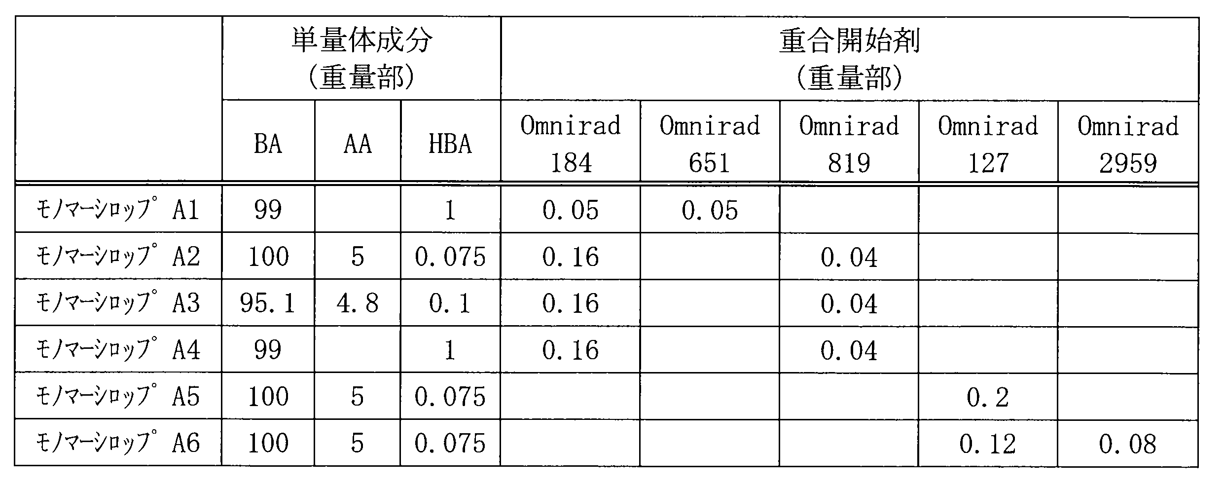
BA:n-ブチルアクリレート
AA:アクリル酸
HBA:4-ヒドロキシブチルアクリレート
Omnirad184:1-ヒドロキシシクロヘキシル-フェニルケトン(Omnirad184、IGM Resins B.V.社製)
Omnirad651:2,2-ジメトキシ-1,2-ジフェニルエタン-1-オン(Omnirad651、IGM Resins B.V.社製)
Omnirad819:ビス(2,4,6-トリメチルベンゾイル)フェニルホスフィンオキサイド(Omnirad819、IGM Resins B.V.社製)
Omnirad127:2-ヒドロキシ-1-(4-(4-(2-ヒドロキシ-2-メチルプロピオニル)ベンジル)フェニル)2-メチルプロパン-1-オン(Omnirad127、IGM Resins B.V.社製)
Omnirad2959:2-ヒドロキシ-4’-(2-ヒドロキシエトキシ)-2-メチルプロピオフェノン(Omnirad2959、IGM Resins B.V.社製)
次に、以下の表2に示す組成となるように、モノマーシロップ、単量体及び架橋剤を混合して、光硬化性組成物C1~C10を得た。
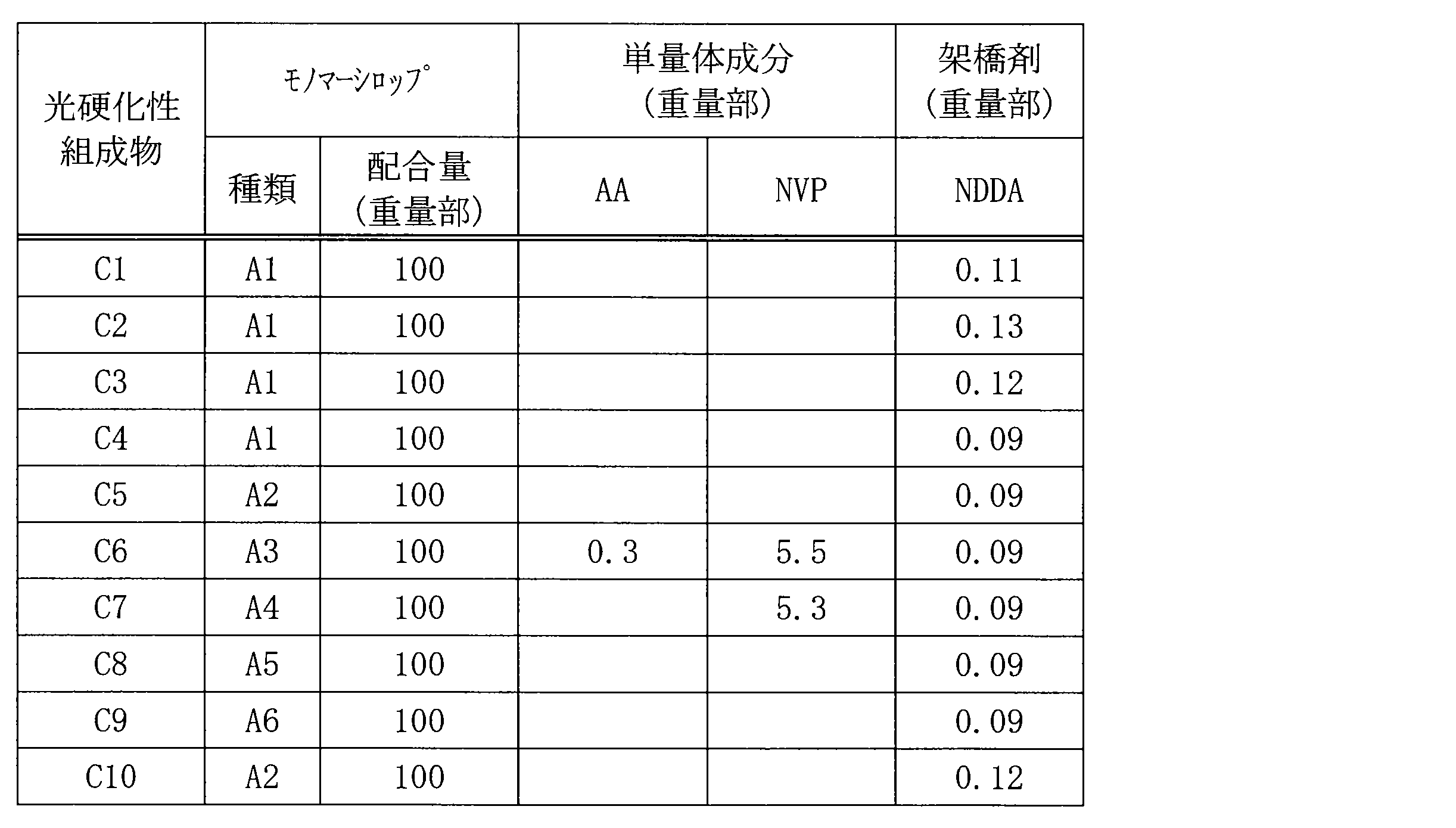
AA:アクリル酸
NVP:N-ビニル-2-ピロリドン
NDDA:1,9-ノナンジオールジアクリレート

BA:n-ブチルアクリレート
AA:アクリル酸
HBA:4-ヒドロキシブチルアクリレート
NVP:N-ビニル-2-ピロリドン
[はく離ライナーの作製]
付加反応硬化型シリコーン(ヘキセニル基含有ポリオルガノシロキサンを含むLTC761、30重量%トルエン溶液、東レ・ダウコーニング製)30重量部、剥離コントロール剤(未反応性シリコーン樹脂を含むBY24-850、東レ・ダウコーニング製)0.9重量部、及び硬化触媒(白金触媒を含むSRX212、東レ・ダウコーニング製)2重量部、及び希釈溶媒としてトルエン/ヘキサン混合溶媒(体積比1:1)を混合して、シリコーン系離型剤組成物を得た。離型剤組成物におけるシリコーン固形分の濃度は、1.0重量%であった。次に、ライナー基材(ポリエステルフィルムであるルミラーXD500P、厚さ75μm)の片面に離型剤組成物をワイヤーバーにより塗布し、130℃で1分間加熱して、離型層(厚さ60nm)を片面に備えるはく離ライナーを作製した。
基材シート(離型層を有さないポリエステルフィルムであるルミラーXD500P、厚さ75μm)の片面に、光硬化性組成物C1をアプリケーターにより塗布し、塗布層(厚さ20μm)を形成した。次に、形成した塗布層の上にはく離ライナーを配置して第1の積層体を得た。はく離ライナーは、離型層が塗布層に接するように配置した。次に、第1の積層体における基材シートの側から、照度9mW/cm2、照射時間160秒の条件でLEDからの光Aを照射した(工程A)。光Aのピーク波長は340nmであった。次に、第1の積層体における基材シートの側から、照度22mW/cm2、照射時間160秒の条件でLEDからの光Bを照射した(工程B)。光Bのピーク波長は365nmであった。工程A及びBにおいて、光の照射は、常温(23℃)下で行った。これにより、塗布層が光硬化し、基材シート及びはく離ライナーに挟持された実施例1の粘着シート(厚さ20μm)を得た。なお、光の照度は、照度計(トプコンテクノハウス社製、UD-T3040T2)を用いて測定した。
使用する光硬化性組成物、光源、及び、光の照射条件を表4に示すように変更したことを除き、実施例1と同じ方法によって、基材シート及びはく離ライナーに挟持された実施例2及び比較例1~3の粘着シートを得た。なお、表4において、「B/L」は、ブラックライト光源を意味する。
実施例1~2及び比較例1~3で作製した粘着シートについて、次の方法によって単量体群の重合率を特定した。まず、粘着シートから基材シート及びはく離ライナーを剥離して、粘着シートの重量W0(乾燥前重量)を測定した。次に、この粘着シートを130℃で2時間加熱乾燥した後、常温(23℃)で約20分冷却してから、粘着シートの重量W1(乾燥後重量)を測定した。重量W0(g)及び重量W1(g)に基づいて、下記式により、単量体群の重合率を算出した。
重合率(%)=W1/W0×100
まず、架橋剤を含まないことを除き、実施例1~2及び比較例1~3で用いた光硬化性組成物と同じ組成を有する試料を準備した。試料に対して、対応する実施例及び比較例の条件で光を照射した。これにより、試料に含まれる単量体群が重合し、ポリマーが形成された。このポリマーについて、数平均分子量(Mn)及び重量平均分子量(Mw)を測定した。
・分析装置:東ソー社製、HLC-8120GPC
・カラム:東ソー社製、G7000HXL+GMHXL+GMHXL
・カラムサイズ:各7.8mmφ×30cm 計90cm
・カラム温度:40℃
・流量:0.8mL/min
・注入量:100μL
・溶離液:テトラヒドロフラン
・検出器:示差屈折計(RI)
・標準試料:ポリスチレン
・分析装置:アジレント・テクノロジー製、Agilent 1200
・カラム:東ソー社製、TSKgel SuperAWM-H+superAW4000+superAW2500
・カラムサイズ:各6.0mmφ×15cm 計45cm
・カラム温度:40℃
・流量:0.4mL/min
・注入量:40μL
・溶離液:N,N-ジメチルホルムアミド(DMF)
・検出器:示差屈折計(RI)
・標準試料:ポリスチレン
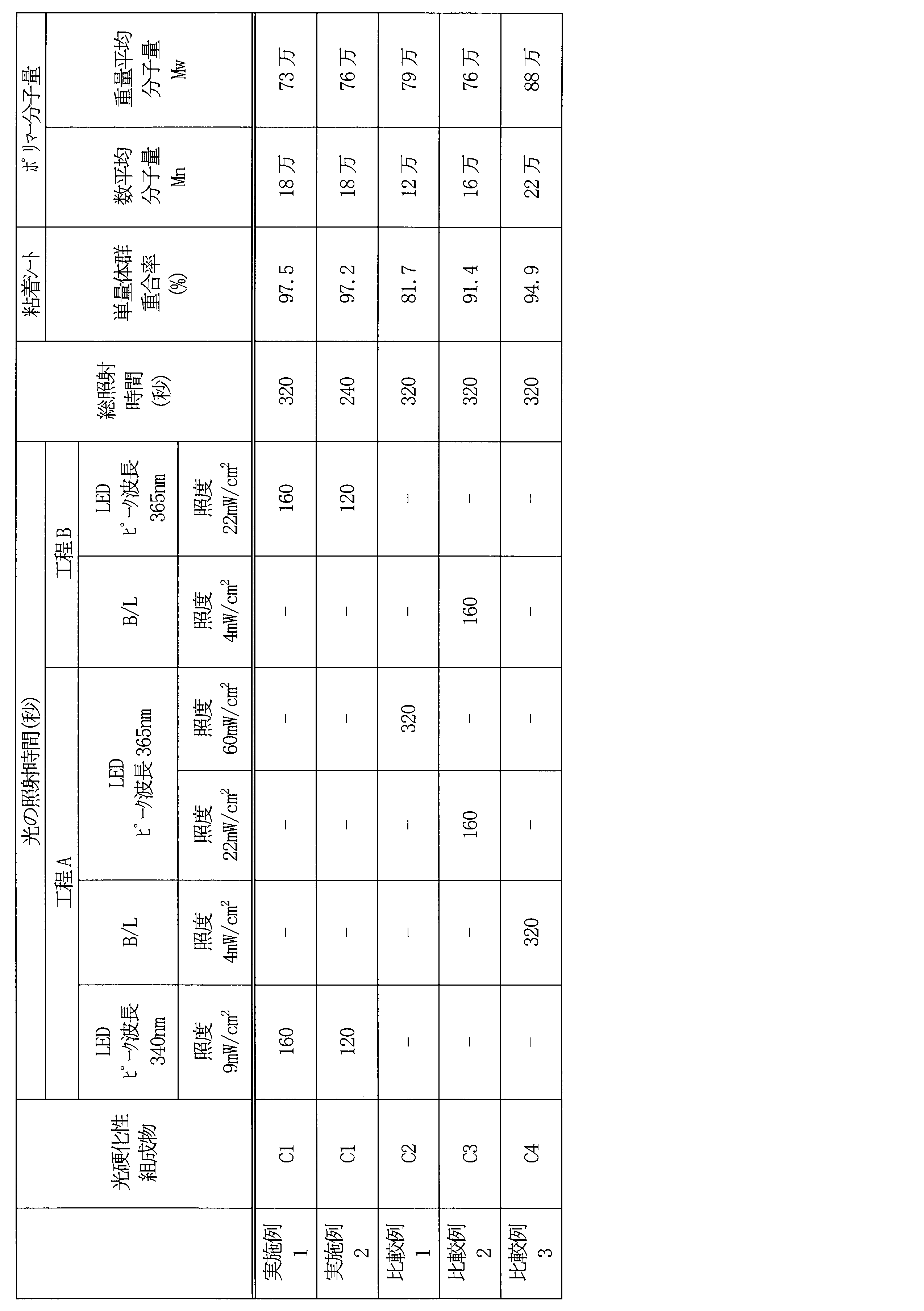
使用する光硬化性組成物、光源、及び、光の照射条件を表5に示すように変更したことを除き、実施例1と同じ方法によって、基材シート及びはく離ライナーに挟持された実施例3~13及び比較例4の粘着シートを得た。なお、実施例4~10では、工程Bの後に、第1の積層体における基材シートの側から、光Cを照射する工程Cをさらに行った。表5において、「B/L」は、ブラックライト光源を意味し、「MH/L」は、メタルハライドランプを意味する。
実施例3~13及び比較例4で作製した粘着シートについて、上述の方法によって、単量体群の重合率を算出した。
架橋剤を含まないことを除き、実施例3~13及び比較例4で用いた光硬化性組成物と同じ組成を有する試料を準備し、上述の方法によって、ポリマーの数平均分子量(Mn)及び重量平均分子量(Mw)を測定した。
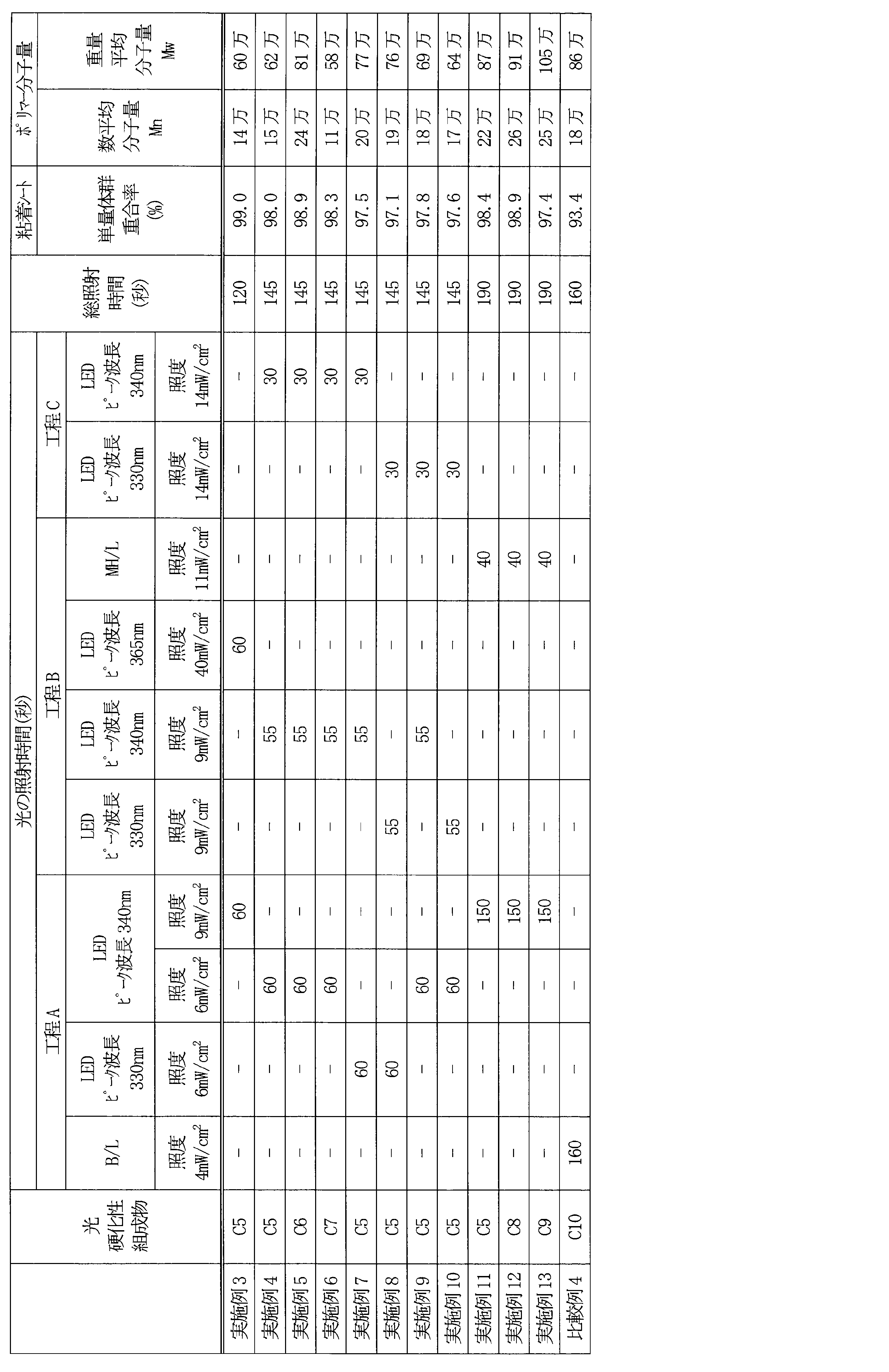
Claims (15)
- 光硬化性組成物を含む塗布層に対して、発光ダイオードからの光Aを照射する工程Aと、
前記工程Aの後に、前記塗布層に対して光Bを照射する工程Bと、
を含み、
前記光Aは、ピーク波長が325nm~350nmであり、
前記塗布層に照射される前記光Bの照度LBは、前記塗布層に照射される前記光Aの照度LAよりも大きい、粘着シートの製造方法。 - 前記ピーク波長が340±10nmである、請求項1に記載の製造方法。
- 前記工程Aにおいて、基材シート、前記塗布層、及びはく離ライナーをこの順に含む積層体に前記光Aを照射する、請求項1に記載の製造方法。
- 前記照度LAは、2.0~30mW/cm2である、請求項1に記載の製造方法。
- 前記照度LAに対する前記照度LBの比が1.2~10である、請求項1に記載の製造方法。
- 前記光Bの光源は、発光ダイオード、メタルハライドランプ及びブラックライト光源からなる群より選ばれる少なくとも1つである、請求項1に記載の製造方法。
- 前記工程Bの後に、前記塗布層に対して光Cを照射する工程Cをさらに含み、
前記塗布層に照射される前記光Cの照度LCは、前記照度LBよりも大きい、請求項1に記載の製造方法。 - 前記光硬化性組成物は、(メタ)アクリル系単量体を含む単量体群及び/又は前記単量体群の部分重合物を含む、請求項1に記載の製造方法。
- 前記工程Aが終了した時点での前記単量体群の重合率が50%以上である、請求項8に記載の製造方法。
- 前記粘着シートにおいて、前記単量体群の重合率が95%以上である、請求項8に記載の製造方法。
- 前記光硬化性組成物は、光重合開始剤を含み、
前記光重合開始剤の配合量が、前記単量体群及び前記部分重合物の合計100重量部に対して1.0重量部以下である、請求項8に記載の製造方法。 - 前記光硬化性組成物における溶剤の含有率が5重量%以下である、請求項1に記載の製造方法。
- 請求項1~12のいずれか1項に記載の製造方法によって形成された粘着シートの露出面に光学フィルムを配置して粘着シート付き光学フィルムを形成することを含む、粘着シート付き光学フィルムの製造方法。
- 前記光学フィルムが、偏光フィルム及び位相差フィルムからなる群より選ばれる少なくとも1つのフィルムを含む、請求項13に記載の製造方法。
- 請求項13に記載の製造方法によって形成された粘着シート付き光学フィルムと画像表示パネルとを接合して画像表示装置を形成することを含む、画像表示装置の製造方法。
Priority Applications (2)
| Application Number | Priority Date | Filing Date | Title |
|---|---|---|---|
| KR1020257035459A KR20250169227A (ko) | 2023-03-31 | 2024-03-13 | 점착 시트의 제조 방법, 점착 시트 구비 광학 필름의 제조 방법 및 화상 표시 장치의 제조 방법 |
| CN202480023300.3A CN120882825A (zh) | 2023-03-31 | 2024-03-13 | 粘合片的制造方法、带粘合片的光学膜的制造方法以及图像显示装置的制造方法 |
Applications Claiming Priority (2)
| Application Number | Priority Date | Filing Date | Title |
|---|---|---|---|
| JP2023059582 | 2023-03-31 | ||
| JP2023-059582 | 2023-03-31 |
Publications (1)
| Publication Number | Publication Date |
|---|---|
| WO2024203365A1 true WO2024203365A1 (ja) | 2024-10-03 |
Family
ID=92905874
Family Applications (1)
| Application Number | Title | Priority Date | Filing Date |
|---|---|---|---|
| PCT/JP2024/009901 Ceased WO2024203365A1 (ja) | 2023-03-31 | 2024-03-13 | 粘着シートの製造方法、粘着シート付き光学フィルムの製造方法及び画像表示装置の製造方法 |
Country Status (5)
| Country | Link |
|---|---|
| JP (2) | JP7620749B2 (ja) |
| KR (1) | KR20250169227A (ja) |
| CN (1) | CN120882825A (ja) |
| TW (1) | TW202513743A (ja) |
| WO (1) | WO2024203365A1 (ja) |
Citations (5)
| Publication number | Priority date | Publication date | Assignee | Title |
|---|---|---|---|---|
| JPH0753849B2 (ja) * | 1988-08-29 | 1995-06-07 | 積水化学工業株式会社 | アクリル系粘着テープもしくはシートの製造方法 |
| JPH07331198A (ja) * | 1994-05-31 | 1995-12-19 | Sony Chem Corp | 粘着テープ及びその製造方法 |
| JP2014111715A (ja) * | 2012-10-31 | 2014-06-19 | Nitto Denko Corp | 紫外線硬化型アクリル系粘着剤層を有する粘着シートの製造方法 |
| JP2021140160A (ja) * | 2020-02-13 | 2021-09-16 | 日東電工株式会社 | 両面粘着剤層付偏光フィルムおよび画像表示装置 |
| JP2023021976A (ja) * | 2019-07-05 | 2023-02-14 | 日東電工株式会社 | 粘着剤層付き偏光フィルム、及び画像表示装置 |
Family Cites Families (1)
| Publication number | Priority date | Publication date | Assignee | Title |
|---|---|---|---|---|
| JP6688054B2 (ja) | 2015-11-27 | 2020-04-28 | 三星エスディアイ株式会社Samsung SDI Co., Ltd. | 粘着剤組成物、光学部材および粘着シート |
-
2024
- 2024-03-13 JP JP2024039509A patent/JP7620749B2/ja active Active
- 2024-03-13 KR KR1020257035459A patent/KR20250169227A/ko active Pending
- 2024-03-13 CN CN202480023300.3A patent/CN120882825A/zh active Pending
- 2024-03-13 WO PCT/JP2024/009901 patent/WO2024203365A1/ja not_active Ceased
- 2024-03-20 TW TW113110284A patent/TW202513743A/zh unknown
-
2025
- 2025-01-10 JP JP2025004056A patent/JP2025039790A/ja active Pending
Patent Citations (5)
| Publication number | Priority date | Publication date | Assignee | Title |
|---|---|---|---|---|
| JPH0753849B2 (ja) * | 1988-08-29 | 1995-06-07 | 積水化学工業株式会社 | アクリル系粘着テープもしくはシートの製造方法 |
| JPH07331198A (ja) * | 1994-05-31 | 1995-12-19 | Sony Chem Corp | 粘着テープ及びその製造方法 |
| JP2014111715A (ja) * | 2012-10-31 | 2014-06-19 | Nitto Denko Corp | 紫外線硬化型アクリル系粘着剤層を有する粘着シートの製造方法 |
| JP2023021976A (ja) * | 2019-07-05 | 2023-02-14 | 日東電工株式会社 | 粘着剤層付き偏光フィルム、及び画像表示装置 |
| JP2021140160A (ja) * | 2020-02-13 | 2021-09-16 | 日東電工株式会社 | 両面粘着剤層付偏光フィルムおよび画像表示装置 |
Also Published As
| Publication number | Publication date |
|---|---|
| TW202513743A (zh) | 2025-04-01 |
| KR20250169227A (ko) | 2025-12-02 |
| CN120882825A (zh) | 2025-10-31 |
| JP7620749B2 (ja) | 2025-01-23 |
| JP2024146804A (ja) | 2024-10-15 |
| JP2025039790A (ja) | 2025-03-21 |
Similar Documents
| Publication | Publication Date | Title |
|---|---|---|
| WO2024019160A1 (ja) | 光学積層体及び画像表示装置 | |
| WO2024203364A1 (ja) | 粘着シートの製造方法、粘着シート付き光学フィルムの製造方法及び画像表示装置の製造方法 | |
| JP2025063955A (ja) | 粘着シートの製造方法及び粘着シート付き光学フィルムの製造方法 | |
| JP2025089324A (ja) | 粘着シート、粘着シート付き光学フィルム、並びに、粘着シート及び粘着シート付き光学フィルムの製造方法 | |
| JP2025063954A (ja) | 粘着シートの製造方法及び粘着シート付き光学フィルムの製造方法 | |
| JP7620749B2 (ja) | 粘着シートの製造方法、粘着シート付き光学フィルムの製造方法及び画像表示装置の製造方法 | |
| WO2024203366A1 (ja) | 粘着シート用光硬化性組成物、粘着シート、光学積層体及び画像表示装置 | |
| JP7688771B2 (ja) | 粘着シート、光学積層体、及び画像表示装置 | |
| WO2024203368A1 (ja) | 粘着シート付き偏光フィルム、光学積層体及び画像表示装置 | |
| WO2024203369A1 (ja) | 粘着シート付き偏光フィルム、光学積層体及び画像表示装置 | |
| WO2024203367A1 (ja) | 粘着シート用光硬化性組成物、粘着シート、光学積層体及び画像表示装置 | |
| JP7644735B2 (ja) | 粘着剤組成物、粘着シート、粘着シート付き光学フィルム、並びに、粘着シート及び粘着シート付き光学フィルムの製造方法 | |
| JP7723646B2 (ja) | 粘着シート及び光学積層体 | |
| WO2025041761A1 (ja) | 粘着シート用光硬化性組成物、粘着シート、光学積層体及び画像表示装置 | |
| WO2025154422A1 (ja) | 粘着剤組成物、粘着シート、光学積層体、及び画像表示装置 | |
| CN121889475A (zh) | 光学粘合片 | |
| WO2024019158A1 (ja) | 粘着シートの製造方法及び粘着シート付き光学フィルムの製造方法 |
Legal Events
| Date | Code | Title | Description |
|---|---|---|---|
| 121 | Ep: the epo has been informed by wipo that ep was designated in this application |
Ref document number: 24779494 Country of ref document: EP Kind code of ref document: A1 |
|
| WWE | Wipo information: entry into national phase |
Ref document number: CN2024800233003 Country of ref document: CN Ref document number: 202480023300.3 Country of ref document: CN |
|
| ENP | Entry into the national phase |
Ref document number: 1020257035459 Country of ref document: KR Free format text: ST27 STATUS EVENT CODE: A-0-1-A10-A15-NAP-PA0105 (AS PROVIDED BY THE NATIONAL OFFICE) |
|
| WWE | Wipo information: entry into national phase |
Ref document number: KR1020257035459 Country of ref document: KR |
|
| WWP | Wipo information: published in national office |
Ref document number: 202480023300.3 Country of ref document: CN |
|
| NENP | Non-entry into the national phase |
Ref country code: DE |
|
| 122 | Ep: pct application non-entry in european phase |
Ref document number: 24779494 Country of ref document: EP Kind code of ref document: A1 |