WO2024203294A1 - 通信及び無線電力伝送を行うシステム、無線処理装置及びアンテナシステム - Google Patents
通信及び無線電力伝送を行うシステム、無線処理装置及びアンテナシステム Download PDFInfo
- Publication number
- WO2024203294A1 WO2024203294A1 PCT/JP2024/009613 JP2024009613W WO2024203294A1 WO 2024203294 A1 WO2024203294 A1 WO 2024203294A1 JP 2024009613 W JP2024009613 W JP 2024009613W WO 2024203294 A1 WO2024203294 A1 WO 2024203294A1
- Authority
- WO
- WIPO (PCT)
- Prior art keywords
- signal
- communication
- power transmission
- wireless power
- antenna
- Prior art date
- Legal status (The legal status is an assumption and is not a legal conclusion. Google has not performed a legal analysis and makes no representation as to the accuracy of the status listed.)
- Ceased
Links
Images









Classifications
-
- H—ELECTRICITY
- H02—GENERATION; CONVERSION OR DISTRIBUTION OF ELECTRIC POWER
- H02J—ELECTRIC POWER NETWORKS; CIRCUIT ARRANGEMENTS OR SYSTEMS FOR SUPPLYING OR DISTRIBUTING ELECTRIC POWER; SYSTEMS FOR STORING ELECTRIC ENERGY
- H02J50/00—Circuit arrangements or systems for wireless supply or distribution of electric power
- H02J50/20—Circuit arrangements or systems for wireless supply or distribution of electric power using microwaves or radio frequency waves
- H02J50/23—Circuit arrangements or systems for wireless supply or distribution of electric power using microwaves or radio frequency waves characterised by the type of transmitting antennas, e.g. directional array antennas or Yagi antennas
-
- H—ELECTRICITY
- H02—GENERATION; CONVERSION OR DISTRIBUTION OF ELECTRIC POWER
- H02J—ELECTRIC POWER NETWORKS; CIRCUIT ARRANGEMENTS OR SYSTEMS FOR SUPPLYING OR DISTRIBUTING ELECTRIC POWER; SYSTEMS FOR STORING ELECTRIC ENERGY
- H02J50/00—Circuit arrangements or systems for wireless supply or distribution of electric power
- H02J50/40—Circuit arrangements or systems for wireless supply or distribution of electric power using two or more transmitting or receiving devices
-
- H—ELECTRICITY
- H02—GENERATION; CONVERSION OR DISTRIBUTION OF ELECTRIC POWER
- H02J—ELECTRIC POWER NETWORKS; CIRCUIT ARRANGEMENTS OR SYSTEMS FOR SUPPLYING OR DISTRIBUTING ELECTRIC POWER; SYSTEMS FOR STORING ELECTRIC ENERGY
- H02J50/00—Circuit arrangements or systems for wireless supply or distribution of electric power
- H02J50/80—Circuit arrangements or systems for wireless supply or distribution of electric power involving the exchange of data, concerning supply or distribution of electric power, between transmitting devices and receiving devices
-
- H—ELECTRICITY
- H04—ELECTRIC COMMUNICATION TECHNIQUE
- H04B—TRANSMISSION
- H04B7/00—Radio transmission systems, i.e. using radiation field
- H04B7/02—Diversity systems; Multi-antenna system, i.e. transmission or reception using multiple antennas
- H04B7/022—Site diversity; Macro-diversity
- H04B7/024—Co-operative use of antennas of several sites, e.g. in co-ordinated multipoint or co-operative multiple-input multiple-output [MIMO] systems
-
- H—ELECTRICITY
- H04—ELECTRIC COMMUNICATION TECHNIQUE
- H04W—WIRELESS COMMUNICATION NETWORKS
- H04W16/00—Network planning, e.g. coverage or traffic planning tools; Network deployment, e.g. resource partitioning or cells structures
- H04W16/24—Cell structures
- H04W16/28—Cell structures using beam steering
Definitions
- the present invention relates to a system, a wireless processing device, and an antenna system capable of performing communication and wireless power transmission (WPT).
- WPT wireless power transmission
- a communication system in which communication is performed between a base station and a terminal device using at least some of a plurality of radio resources set in a radio frame (see, for example, Patent Document 1).
- terminal devices that connect to base stations to communicate include portable terminal devices that mainly use power supplied from an internal battery. These terminal devices require the cumbersome task of charging the internal battery when the remaining charge is low. Furthermore, terminal devices that use power supplied from a wired power line rather than from an internal battery are limited to use in locations where such a power line is available. As such, there is no power supply infrastructure in place that can supply power to the various terminal devices that connect to base stations to communicate.
- next generation mobile communication systems a rapid increase in terminal devices (e.g., user equipment, IoT devices, etc.) that connect to base stations and communicate is expected, and progress is being made in developing a communications infrastructure that can handle the huge amount of traffic.
- terminal devices e.g., user equipment, IoT devices, etc.
- a power supply infrastructure capable of supplying power to the huge number of terminal devices that will be communicating as described above remains underdeveloped.
- a system that uses a mobile communication base station for wireless power transmission (WPT) is being considered as a power supply infrastructure for supplying power to the above-mentioned terminal devices.
- WPT wireless power transmission
- One of the issues with such a system is that, due to restrictions on the transmission power of radio waves sent from the base station during wireless power transmission, the wireless power transmission area in which the terminal device can receive the power of the radio waves from the base station is sometimes narrower than the communication area in which the base station can communicate with the terminal device.
- An antenna system is an antenna system that can be used for communication and wireless power transmission in a mobile communication system.
- This antenna system includes a first array antenna that is used for both communication and wireless power transmission, and a plurality of second array antennas dedicated to wireless power transmission that are distributed around the area around the first array antenna and spaced apart from the first array antenna.
- the antenna system may include a plurality of first radio signal processing units connected to each of the plurality of antenna elements of the first array antenna, amplifying a plurality of high-frequency signals corresponding to a dummy signal for downlink wireless power transmission, a downlink communication signal, and an uplink communication signal, using different amplifiers, and multiplexing and transmitting the plurality of high-frequency signals via the antenna elements; and a plurality of second radio signal processing units provided for each of the plurality of second array antennas, connected to each of the plurality of antenna elements of the second array antenna, amplifying a high-frequency signal corresponding to a dummy signal for downlink wireless power transmission, and transmitting the high-frequency signal via the antenna elements.
- each of the first wireless signal processing units may include a first phase shifter for controlling the phase of the dummy signal for wireless power transmission transmitted from the antenna element, a first amplifier for amplifying the dummy signal for wireless power transmission, a second phase shifter for controlling the phase of the downlink communication signal transmitted from the antenna element, a second amplifier for amplifying the downlink communication signal, a third amplifier for amplifying the uplink communication signal received via the antenna element, and a third phase shifter for controlling the phase of the uplink communication signal.
- the first amplifier may be a bias adjustment type high efficiency amplifier or a waveform processing type high efficiency amplifier
- the second amplifier may be an amplifier that improves efficiency in a linear region
- the third amplifier may be a low noise amplifier.
- each of the second wireless signal processing units may include a fourth phase shifter for controlling the phase of the dummy signal for wireless power transmission transmitted from the antenna element, and a fourth amplifier for amplifying the dummy signal for wireless power transmission.
- the fourth amplifier may be a bias adjustment type high efficiency amplifier or a waveform processing type high efficiency amplifier.
- each of the first wireless signal processing units may include a multiplexing processor that multiplexes the dummy signal for wireless power transmission, the downlink communication signal, and the uplink communication signal by a time division duplex (TDD) method.
- a frame for wireless power transmission used for the dummy signal for wireless power transmission, a frame for downlink communication used for the downlink communication signal, and a frame for uplink communication used for the uplink communication signal may be time-divided and assigned to a communication frame, and the multiplexing processor may switch the connection between the antenna element and each of the signal processing paths for the dummy signal for wireless power transmission, the downlink communication signal, and the uplink communication signal in synchronization with the frame for wireless power transmission, the frame for downlink communication, and the frame for uplink communication.
- each of the first wireless signal processing units may include a multiplexing processor that multiplexes the wireless power transmission dummy signal, the downlink communication signal, and the uplink communication signal by frequency division duplexing (FDD).
- the first array antenna may include a wireless power transmission array antenna used to transmit the wireless power transmission dummy signal, and a communication array antenna used to transmit the downlink communication signal and receive the uplink communication signal
- the first wireless signal processing units may include a plurality of wireless power transmission wireless signal processing units that are connected to each of the antenna elements of the wireless power transmission array antenna, amplify the high-frequency signal of the wireless power transmission dummy signal with a wireless power transmission amplifier, and transmit it via the antenna element, and a plurality of communication wireless signal processing units that are connected to each of the antenna elements of the communication array antenna, amplify the high-frequency signals of the downlink communication signal and the uplink communication signal with different amplifiers, and multiplex the high-frequency signals via the antenna elements to transmit and receive the multiple high-frequency signals.
- a radio processing device includes any one of the antenna systems and an input/output signal processing unit connected to the plurality of first radio signal processing units and connected to the plurality of second radio signal processing units via a signal transmission line.
- the input/output signal processing unit includes a signal separation unit that separates a downlink intermediate frequency signal including the dummy signal for wireless power transmission and the downlink communication signal into an intermediate frequency signal of the dummy signal for wireless power transmission and an intermediate frequency signal of the downlink communication signal, a first mixer that mixes the intermediate frequency signal of the dummy signal for wireless power transmission separated by the signal separation unit with a local oscillation signal of a predetermined frequency to generate a high frequency signal of the dummy signal for wireless power transmission, a second mixer that mixes the intermediate frequency signal of the downlink communication signal with the local oscillation signal to generate a high frequency signal of the downlink communication signal, and a third mixer that mixes the high frequency signal of the uplink communication signal with the local oscillation signal to generate an intermediate frequency signal of the uplink communication signal.
- a radio processing device comprises any one of the antenna systems and an input/output signal processing unit connected to the plurality of first radio signal processing units and connected to the plurality of second radio signal processing units via a signal transmission line.
- the input/output signal processing unit includes a signal separation unit that separates a first branch signal, obtained by branching a downlink intermediate frequency signal including the dummy signal for wireless power transmission and the downlink communication signal, into an intermediate frequency signal of the dummy signal for wireless power transmission and an intermediate frequency signal of the downlink communication signal; a first mixer that mixes the intermediate frequency signal of the dummy signal for wireless power transmission separated by the signal separation unit with a local oscillation signal of a predetermined frequency to generate a high frequency signal of the dummy signal for wireless power transmission; a termination unit that terminates the intermediate frequency signal of the downlink communication signal separated by the signal separation unit; a second mixer that mixes a second branch signal, obtained by branching a downlink intermediate frequency signal including the dummy signal for wireless power transmission and the downlink communication
- a system is a system for wireless power transmission to a terminal device of a mobile communication system.
- This system includes any one of the wireless processing devices described above, and a communication signal processing unit that generates a downlink intermediate frequency signal including a dummy signal for wireless power transmission and the downlink communication signal, and processes an uplink intermediate frequency signal including the uplink communication signal.
- the system may include a central station having the first array antenna, the plurality of first radio signal processing units, and the input/output signal processing unit, and a plurality of base stations connected to the input/output signal processing unit of the central station via the signal transmission line, each having the first array antenna and the plurality of first radio signal processing units.
- the multiple base stations may perform beamforming control independent of each other and perform wireless power transmission individually to each of the multiple terminal devices.
- the base station may acquire position information of terminal devices located in the vicinity, and perform beamforming control for the terminal devices based on the position information of the terminal devices.
- the base station may also capture images of the vicinity of the base station, and acquire position information of the terminal devices based on the captured images.
- the central station may include a remote radio head device having the first array antenna and the plurality of first radio signal processing units, and a baseband unit device having the communication signal processing unit, which is disposed at a position away from the remote radio head device and connected to the remote radio head device via a signal transmission line.
- the system may include a terminal device capable of wireless power transmission via the first array antenna or the second array antenna of the wireless processing device, and the terminal device may have a wireless processing unit that receives a transmission signal including a dummy signal for wireless power transmission transmitted from the wireless processing device, and a power output unit that outputs, as received power, the power of a received signal that receives the transmission signal including the dummy signal for wireless power transmission.
- the area in which wireless power can be transmitted from a base station can be expanded to approach the area in which communication is possible.
- FIG. 1 is an explanatory diagram illustrating an example of the overall configuration of a system according to an embodiment.
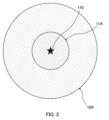
- FIG. 2 is an explanatory diagram showing an example of a communication area and a WPT area in a system according to a comparative reference example.
- FIG. 3 is an explanatory diagram showing an example of a communication area and a WPT area in the system according to the embodiment.
- FIG. 4 is a block diagram showing an example of the configuration of a base station (aggregate station), a base station, and a terminal device that constitute the system according to the embodiment.
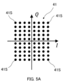
- FIG. 5A is an explanatory diagram showing an example of an arrangement of symbol points in primary modulation of the QAM method of a communication signal transmitted from a base station (aggregate station) according to the embodiment.
- FIG. 5B is an explanatory diagram showing an example of an arrangement of symbol points in modulation of a WPT dummy signal transmitted from a base station (aggregation station) according to the embodiment.
- FIG. 6 is a graph showing an example of input/output power characteristics and efficiency characteristics of the power amplifiers of the base station (aggregate station) and the base station according to the embodiment.
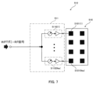
- FIG. 7 is a block diagram showing an example of the configuration of an antenna system applicable to the base station according to the embodiment.
- FIG. 8 is a block diagram showing an example of the configuration of an antenna system applicable to the base station (aggregation station) according to the embodiment.
- FIG. 9 is a block diagram showing an example of the configuration of a radio signal processing unit that constitutes the antenna system of FIG. FIG.
- FIG. 10 is an explanatory diagram showing an example of a frame configuration of a signal transmitted and received by the antenna system of FIG.
- FIG. 11 is a block diagram showing another example of the configuration of an antenna system applicable to the base station (aggregation station) according to the embodiment.
- 12 is a block diagram showing an example of the configuration of a radio signal processing unit that constitutes the antenna system of FIG. 11.
- FIG. 13 is a block diagram showing an example of the configuration of an antenna system having a separate antenna configuration applicable to the base station (aggregation station) according to the embodiment.
- FIG. 14A is a block diagram showing an example of the configuration of a wireless signal processing unit for wireless power transmission (WPT) that constitutes the antenna system of FIG. 13 .
- WPT wireless power transmission
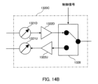
- FIG. 14B is a block diagram showing an example of the configuration of a wireless signal processing unit for communication that constitutes the antenna system of FIG. 13.
- FIG. 15 is a block diagram showing another example of the configuration of the wireless signal processing unit for communication that constitutes the antenna system of FIG.
- FIG. 16 is a block diagram showing an example of the overall configuration of a system including a base station (aggregate station) and a plurality of base stations according to the embodiment.
- FIG. 17 is a block diagram showing another example of the overall configuration of a system including a base station (aggregate station) and a plurality of base stations according to the embodiment.
- FIG. 18 is an explanatory diagram illustrating an example of power supply to each of a plurality of terminal devices by beamforming according to the embodiment.
- the system according to the embodiment described in this specification is a system capable of wireless power transmission (WPT) from a mobile communication base station to a terminal device (e.g., a mobile communication UE (mobile station) or an IoT device) to be powered.
- the system according to the embodiment is a system that effectively utilizes unused wireless resources (resource blocks) that are not used for communication among a plurality of wireless resources (resource blocks) set in a downlink wireless frame to a terminal device such as a UE, for wireless power transmission (WPT) to the terminal device.
- the system according to the embodiment may be a wireless communication system between a base station and a terminal device having a wireless power transmission (WPT) function from the base station to the terminal device.
- the system according to the embodiment may also be a wireless power transmission (WPT) system from a base station to a terminal device having a wireless communication function between the base station and the terminal device.
- WPT wireless power transmission
- the transmission signal for wireless power transmission sent from the base station is transmitted from the communication/WPT antenna (first array antenna) of the aggregation station, and can also be transmitted from WPT antennas (second array antennas) dedicated to wireless power transmission of multiple base stations that are distributed away from the communication/WPT antenna in an area centered on the communication/WPT antenna, so that the area where wireless power transmission from the base station is possible can be expanded so as to approach the area where communication is possible (hereinafter also referred to as the "communication area").
- FIG. 1 is an explanatory diagram showing an example of a schematic configuration of a system according to an embodiment.
- the system according to this embodiment has a cellular base station (hereinafter also referred to as an "aggregator station") 10 that forms a communication area (cell) 10A and a wireless power transmission area (hereinafter also referred to as a "WPT area”) 11A, and a number of base stations 50 connected to the base station (aggregator station) 10 via a signal transmission line 60.
- the system may also include a terminal device (hereinafter also referred to as a "UE" (user equipment)) 20 that is a power supply target and can connect to the base station 10 and wirelessly communicate with the base station 10 when present in the communication area 10A.
- UE user equipment
- UE20 may be a mobile station of a mobile communication system, or may be a combination of a communication device (e.g., a mobile communication module) and various devices. UE20 is equipped with, for example, an array antenna having multiple antenna elements. UE20 may be an IoT device (also called "IoT equipment").
- the base station 10 is equipped with multiple array antennas 110 having many antenna elements, and can communicate with multiple UEs 20 using a massive MIMO (hereinafter also referred to as "mMIMO") transmission method.
- mMIMO is a wireless transmission technology that achieves large-capacity, high-speed communication by transmitting and receiving data using the array antennas 110.
- the base station 10 can also communicate with multiple UEs 20 using a multi-user (MU)-MIMO transmission method, which performs beamforming to form beams 10B for each of the multiple UEs 20 in a time-division or simultaneous manner.
- MU multi-user
- the central part of communication area 10A centered on array antenna 110 as a first array antenna used for both communication and wireless power transmission of base station (aggregation station) 10, is WPT area 11A where wireless power transmission is performed directly from base station 10 to UE 20.
- WPT area 11A is narrower than communication area 10A as shown in the figure.
- array antennas 510(1) to 510(6) of multiple base stations 50(1) to 50(6) are provided as multiple second array antennas dedicated to wireless power transmission, which are distributed away from the array antenna 110 of the base station 10.
- the WPT area 11A of the base station 10 is substantially expanded to an area size equivalent to that of the communication area 10A. Note that, in the example of Fig. 3, the number of array antennas 510(1) to 510(6) of the base stations 50(1) to 50(6) is illustrated as six, but the number of base stations 50 and array antennas 510 may be two to five, or seven or more.
- unused radio resources are used as wireless power transmission blocks.
- the base station 10 generates a transmission signal in which a dummy signal for wireless power transmission (hereinafter also referred to as a "WPT dummy signal") is assigned to the wireless power transmission block (WPT block), which is an unused radio resource, in the downlink radio frame to the UE 20, and transmits the signal to the UE 20 in the WPT area 11A, and also transmits the signal to each of the base stations 50(1) to 50(6) via the signal transmission line 60.
- the base stations 50(1) to 50(6) each transmit the transmission signal received from the base station 10 to the UE 20 in the WPT area 51A.
- a technology called lean carrier has been proposed in which the minimum necessary reference signals (RS) and control signals are placed on only some of the subcarriers of a radio frame, and it is expected that the unused radio resources in the radio frame can be effectively utilized to transmit wireless power to UE 20.
- RS minimum necessary reference signals
- control signals are placed on only some of the subcarriers of a radio frame, and it is expected that the unused radio resources in the radio frame can be effectively utilized to transmit wireless power to UE 20.
- the radio waves of the communication signals transmitted and received between the base station 10 and the UE 20 and the radio waves of the transmission signals assigned with the WPT dummy signal transmitted from the base station 10 to the UE 20 are, for example, millimeter waves or microwaves.
- FIG. 4 is a block diagram showing an example of the main configuration of a base station (aggregation station) 10, a base station 50, and a terminal device (UE) 20 that constitute the system according to the embodiment.
- the base station 10 includes an antenna 110, a communication signal processing unit 120, and a radio processing device (radio processing unit) 130.
- the base station 10 in FIG. 4 may also include a remote radio head (RRH) having a radio processing device 130, and a baseband unit (BBU) having a communication signal processing unit 120.
- the baseband unit (BBU) is disposed at a location away from the remote radio head (RRH) and is connected to the remote radio head via a wired communication line (e.g., an optical line made of optical fiber).
- the antenna 110 is, for example, an array antenna having a large number of antenna elements as shown in FIG. 1. There may be a single antenna 110 or multiple antennas. For example, multiple antennas 110 may be arranged to correspond to multiple sector cells.
- the communication signal processing unit 120 is composed of, for example, an FPGA (Field Programmable Gate Array), and processes signals such as various user data and control information transmitted and received between the UE 20.
- FPGA Field Programmable Gate Array
- the communication signal processing unit 120 generates a downlink transmission signal including a WPT dummy signal using unused radio resources among the multiple radio resources during downlink communication with the UE 20.
- the WPT dummy signal can be generated by modulating it with a modulation method that has a smaller PAPR (peak-to-average power ratio) (also called "peak height ratio") than the communication signal.
- the WPT dummy signal may be a modulated signal modulated with a code of a Zadoff-Chu sequence, with a constant amplitude and a variable phase over time, or may be a signal modulated with multiple symbol points whose amplitude is maximum or near maximum among multiple symbol points of a digital modulation method.
- the generation of the transmission signal may include primary modulation such as QAM (quadrature amplitude modulation) for communication signals and modulation with a small PAPR for the WPT dummy signal, as well as secondary modulation such as OFDM (orthogonal frequency division multiplexing) modulation.
- primary modulation such as QAM (quadrature amplitude modulation) for communication signals and modulation with a small PAPR for the WPT dummy signal
- secondary modulation such as OFDM (orthogonal frequency division multiplexing) modulation.
- the wireless processing device 130 transmits the transmission signal generated by the communication signal processing unit 120 from the antenna 110 to the UE 20, outputs the reception signal received from the UE 20 via the antenna 110 to the communication signal processing unit 120, and transmits the high-frequency wireless signal (RF signal) of the WPT dummy signal to the base station 50.
- RF signal high-frequency wireless signal
- the process of including a WPT dummy signal using unused radio resources in the transmission signal for downlink communication to UE 20, and the generation of a control signal (trigger signal) used for signal separation and signal synthesis, etc., described below, may be performed based on subframes that constitute the radio frame of mobile communication.
- the process of including a WPT dummy signal using unused radio resources in a transmission signal for downlink communication to UE 20 may be performed autonomously by base station 10, or may be performed based on a request or instruction from UE 20 or a request or instruction from an external platform (e.g., a server, a cloud system).
- an external platform e.g., a server, a cloud system.
- the radio processing device 130 controls one or more beams formed by the array antenna 110 based on the BF control signal.
- the radio processing device 130 also transmits a downlink transmission signal including a WPT dummy signal generated by the communication signal processing unit 120 to the UE 20 via the antenna 110.
- the base station 10 may perform beamforming (BF) control to form an individual beam 10B for each UE 20 or for each UE group in a target area to which multiple UEs 20 belong during downlink communication with the UE 20, and may perform wireless power transmission for each UE 20 or for each UE group.
- the BF control for each UE 20 or for each UE group may be performed by digital BF control in the frequency domain in the communication signal processing unit 120, or may be performed by analog BF control in the radio processing device 130.
- the wireless processing device 130 includes an input/output signal processing unit 131, an antenna system 133 having a wireless signal processing unit (hereinafter also referred to as an "RF signal processing unit") 132 and an antenna 110, and a transmission signal conversion unit 134.
- the transmission signal conversion unit 134 converts the RF signal of the WPT dummy signal (WPT dummy RF signal) transmitted to the base station 50 into a transmission signal that can be transmitted through the signal transmission line 60.
- the transmission signal conversion unit 134 can use an E/O (electrical signal/optical signal) converter that converts the electrical signal of the WPT dummy RF signal into an optical signal (transmission signal).
- E/O electrical signal/optical signal
- the base station 50 includes an antenna system 512 having a radio signal processing unit (hereinafter also referred to as an "RF signal processing unit") 511 and an antenna 510, and a transmission signal conversion unit 513.
- the RF signal processing unit 511 controls the phase of the WPT dummy RF signal supplied to each antenna element of the antenna 510 to a predetermined phase, thereby performing beamforming control via the antenna 510 to transmit the WPT dummy RF signal.
- the transmission signal conversion unit 513 converts the transmission signal received from the base station (aggregation station) 10 via the signal transmission line 60 into a WPT dummy RF signal that can be processed by the RF signal processing unit 511.
- the transmission signal conversion unit 513 can use an O/E (optical signal/electrical signal) converter that converts an optical signal (transmission signal) into an electrical signal of the WPT dummy RF signal.
- O/E optical signal/electrical signal
- the UE 20 includes an antenna 210, a radio processing unit 220, a communication signal processing unit 230, a power output unit 240, and a battery 250.
- the antenna 210 is, for example, a small array antenna having multiple antenna elements.
- the radio processing unit 220 transmits transmission signals such as feedback information and user data generated by the communication signal processing unit 230 from the antenna 210 to the base station 10, and outputs received signals received from the base station 10 via the antenna 210 to the communication signal processing unit 230.
- the wireless processing unit 220 receives a transmission signal (WPT dummy RF signal) including a WPT dummy signal transmitted from the base station (aggregation station) 10 or the base station 50.
- the power output unit 240 has, for example, a rectifier, and outputs the power of the received signal that received the transmission signal (WPT dummy RF signal) including a WPT dummy signal from the base station (aggregation station) 10 or the base station 50 as received power for charging the battery.
- the battery 250 can be charged by the received power output from the power output unit 240.
- FIG. 5A is an explanatory diagram showing an example of the arrangement of symbol points 41 in the primary modulation of the QAM method of a communication signal transmitted from the base station 10 according to this embodiment.
- FIG. 5A is a constellation diagram showing the arrangement of multiple symbol points (64-value symbol points) in the case of the 64QAM method.
- FIG. 5B is an explanatory diagram showing an example of the arrangement of symbol points in the modulation of a WPT dummy signal transmitted from the base station 10 according to this embodiment.
- the horizontal axis indicates the in-phase channel component
- the vertical axis indicates the orthogonal channel component.
- an OFDM modulated signal with a lower PAPR (peak-to-average power ratio) than the communication signal is used as the WPT dummy signal.
- a WPT dummy signal may be used that is an OFDM modulated signal modulated only by the outermost or surrounding symbol points 41S with the largest amplitude among the multiple symbol points 41 of the QAM method for the communication signal.
- a WPT dummy signal may be used that is an OFDM modulated signal modulated at symbol point 42 where the phase changes with constant amplitude over time.
- the OFDM modulated signal at symbol point 42 in FIG. 5B can be generated using, for example, a code of the Zadoff-Chu sequence.
- FIG. 6 is a graph showing an example of the characteristics of the output power Pout [dBm] and the amplifier efficiency PAE [%] with respect to the input power Pin [dBm] of the amplifier of the base station 10 according to this embodiment.
- Curve A in the figure is a simulation calculation result of the input/output characteristics showing the AC output power Pout [dBm] with respect to the AC input power Pin [dBm] of the amplifier.
- dashed curves B, C, and D in the figure are respectively a simulation calculation result of the PAE (power added efficiency) [%], which is one of the index values of the efficiency with respect to the input power Pin [dBm] of the amplifier suitable for the uplink (UL) communication signal, the downlink (DL) communication signal, and the WPT dummy signal.
- the PAE [%] of the amplifier is defined as (Pout-Pin)/Pdc.
- Pdc is the DC power input (applied) to the amplifier.
- the region where the relationship between the input power Pin and the output power Pout is linear or nearly linear is suitable for low noise amplification of UL communication signals and power amplification of DL communication signals.
- the characteristics of an amplifier suitable for amplifying UL communication signals require, for example, a high PAPR (peak-to-average power ratio), high linearity, a wide dynamic range, and low noise.
- the characteristics of a power amplifier suitable for amplifying DL communication signals require, for example, a high PAPR, high linearity, and a wide dynamic range. Examples of such power amplifiers include amplifiers that improve efficiency in the linear region, such as Doherty amplifiers, envelope tracking amplifiers, and outphasing amplifiers. It is.
- the saturation region of the input/output characteristic A in FIG. 6 is a region where the output power Pout is saturated or nearly saturated with respect to an increase in the input power Pin.
- the peak of the power amplifier efficiency PAE is located in the region near the boundary between the linear region and the saturation region, and this region is suitable for high-output and high-efficiency power amplification of the WPT dummy signal.
- the characteristics of a power amplifier suitable for amplifying the WPT dummy signal require, for example, high efficiency, low PAPR, and large output power.
- Examples of such power amplifiers include high-efficiency amplifiers of bias adjustment type such as class A amplifiers, class B amplifiers, class C amplifiers, and class AB amplifiers, and high-efficiency amplifiers of waveform processing type such as class E amplifiers, class F amplifiers, and class J amplifiers.
- bias adjustment type such as class A amplifiers, class B amplifiers, class C amplifiers, and class AB amplifiers
- high-efficiency amplifiers of waveform processing type such as class E amplifiers, class F amplifiers, and class J amplifiers.
- PAPR peak-to-average power ratio
- the WPT dummy signal, DL communication signal, and UL communication signal may each be amplified by an amplifier suitable for each signal.
- the antenna system 133 of the base station (aggregator station) 10 or base station 50 multiple signal processing paths corresponding to the WPT dummy signal, DL communication signal, and UL communication signal, respectively, may be configured, and each of the multiple signal processing paths may be provided with an individual amplifier suitable for each signal.
- FIG. 7 is a block diagram showing an example of the configuration of an antenna system applicable to the base station 50 according to the embodiment.
- the antenna system 512 includes an array antenna (WPT array antenna) 510 for wireless power transmission (WPT) consisting of multiple (Nw) antenna elements 5101(1) to 5101(Nw), and an RF signal processing unit 511 for wireless power transmission (WPT) connected to the WPT array antenna 510.
- WPT array antenna for wireless power transmission
- Nw multiple
- WPT RF signal processing unit 511 for wireless power transmission
- the RF signal processing unit 511 for wireless power transmission has a plurality of (Nw) wireless signal processing units (hereinafter also referred to as "WPT dummy RF signal processing units") 5110(1) to 5110(Nw) that correspond one-to-one to the plurality of (Nw) antenna elements 5101(1) to 5101(Nw) of the array antenna 510.
- the plurality of WPT dummy RF signal processing units 5110(1) to 5110(Nw) are respectively connected to the corresponding antenna elements 5101(1) to 5101(Nw).
- the WPT dummy RF signal processing units 5110(1) to 5110(Nw) transmit the WPT dummy RF signal by controlling the phase of the WPT dummy RF signal to a predetermined phase and performing beamforming control via the antenna elements 5101(1) to 5101(Nw).
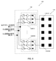
- FIG. 8 is a block diagram showing an example of the configuration of an antenna system 133 applicable to a base station (aggregator station) 10 according to an embodiment.
- the antenna system 133 includes an array antenna 110 consisting of multiple (N) antenna elements 1101(1) to 1101(N), and a TDD (time division duplex) RF signal processing unit 132 connected to the array antenna 110.
- N multiple antenna elements 1101(1) to 1101(N)
- TDD time division duplex
- the RF signal processing unit 132 has a plurality (N) of radio signal processing units (hereinafter also referred to as "RF signal processing units") 1320(1) to 1320(N) that correspond one-to-one to the plurality (N) of antenna elements 1101(1) to 1101(N) of the array antenna 110.
- RF signal processing units radio signal processing units
- the plurality of RF signal processing units 1320(1) to 1320(N) are respectively connected to the corresponding antenna elements 1101(1) to 1101(N) and amplify the WPT dummy RF signal, DL communication RF signal, and UL communication RF signal, which are high-frequency transmission signals of the downlink WPT dummy signal and DL communication signal, and the uplink UL communication signal, by a plurality of different amplifiers and multiplex them using the TDD (time division duplex) method.
- TDD time division duplex
- the RF signal processing units 1320(1) to 1320(N) each control the phase of the WPT dummy RF signal, DL communication RF signal, and UL communication RF signal to a predetermined phase, thereby performing beamforming control via the antenna elements 1101(1) to 1101(N) to transmit and receive each signal.
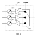
- FIG. 9 is a block diagram showing an example of the configuration of an RF signal processing unit 1320 constituting the antenna system 133 of FIG. 8. Note that since the multiple RF signal processing units 1320(1) to 1320(N) have similar configurations, FIG. 9 describes one RF signal processing unit 1320 with the identification number in parentheses omitted.
- the RF signal processing unit 1320 includes a first phase shifter 1321W for controlling the phase of the WPT dummy RF signal transmitted from the antenna element 1101, and a first amplifier (power amplifier) 1322W for amplifying the WPT dummy RF signal.
- the RF signal processing unit 1320 further includes a second phase shifter 1321D for controlling the phase of the DL communication RF signal transmitted from the antenna element 1101, a second amplifier (power amplifier) 1322D for amplifying the DL communication RF signal, a third amplifier (low noise amplifier) 1322U for amplifying the UL communication RF signal received via the antenna element 1101, and a third phase shifter 1321U for controlling the phase of the UL communication RF signal.
- the RF signal processing unit 1320 also includes a signal changeover switch 1323 as a multiplexing processing unit that multiplexes the WPT dummy RF signal, the DL communication RF signal, and the UL communication RF signal using a time division duplex (TDD) method.
- the signal changeover switch 1323 switches the connection between the antenna element 1101 and each of the signal processing paths for the WPT dummy RF signal, the DL communication RF signal, and the UL communication RF signal based on a predetermined control signal.
- the control signal may be generated, for example, in the communication signal processing unit 120 based on predetermined baseband scheduling information.
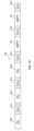
- FIG. 10 is an explanatory diagram showing an example of the frame configuration of a WPT dummy signal, DL communication signal, and UL communication signal transmitted and received by the antenna system 133 in FIG. 8.
- the periods marked with "WPT”, "DL”, and “UL” in FIG. 10 are respectively a WPT frame 32 for transmitting a WPT dummy signal, a DL communication frame 31D for transmitting a DL communication signal, and a UL communication frame 31U for receiving a UL communication signal, which are assigned to a frame 30 of wireless communication between the base station 10 and the terminal device 20.
- the hatched periods in FIG. 10 are guard periods during which no signals are transmitted or received.
- the signal changeover switch 1323 may switch the connection between the antenna element 1101 and three signal processing paths via amplifiers 1322W, 1322D, and 1322U for the WPT dummy RF signal, DL communication RF signal, and UL communication RF signal, respectively, in synchronization with the WPT frame 32, DL communication frame 31D, and UL communication frame 31U. For example, by switching the signal processing paths of the signal changeover switch 1323, the WPT dummy RF signal output from the first amplifier (power amplifier) 1322W during the period of the WPT frame 32 is supplied to the antenna element 1101.
- the DL communication RF signal output from the second amplifier (power amplifier) 1322D is supplied to the antenna element 1101, and during the UL communication frame 31U, the UL communication RF signal output from the antenna element 1101 is supplied to the third amplifier (low noise amplifier) 1322U.
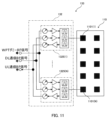
- FIG. 11 is a block diagram showing another example of the configuration of an antenna system 133 applicable to the base station (aggregation station) 10 according to the embodiment.
- the antenna system 133 includes an array antenna 110 consisting of multiple (N) antenna elements 1101(1) to 1101(N), and an RF signal processing unit 132 of the FDD (frequency division duplex) type connected to the array antenna 110.
- the RF signal processing unit 132 has a plurality (N) of radio signal processing units (RF signal processing units) 1325(1) to 1325(N) that correspond one-to-one to the plurality (N) of antenna elements 1101(1) to 1101(N) of the array antenna 110.
- the plurality of RF signal processing units 1325(1) to 1325(N) are respectively connected to the corresponding antenna elements 1101(1) to 1101(N), and amplify the WPT dummy RF signal, DL communication RF signal, and UL communication RF signal using a plurality of different amplifiers, and multiplex them using the FDD (frequency division duplex) method.
- FDD frequency division duplex
- the RF signal processing units 1325(1) to 1325(N) each control the phase of the WPT dummy RF signal, DL communication RF signal, and UL communication RF signal to a predetermined phase, thereby performing beamforming control via the antenna elements 1101(1) to 1101(N) to transmit and receive each signal.
- FIG. 12 is a block diagram showing an example of the configuration of an RF signal processing unit 1325 constituting the antenna system 133 of FIG. 11. Note that since the multiple RF signal processing units 1325(1) to 1325(N) have similar configurations, FIG. 12 describes one RF signal processing unit 1325 with the identification number in parentheses omitted.
- the RF signal processing unit 1325 includes a first phase shifter 1321W for controlling the phase of the WPT dummy RF signal transmitted from the antenna element 1101, and a first amplifier (power amplifier) 1322W for amplifying the WPT dummy RF signal.
- the RF signal processing unit 1325 further includes a second phase shifter 1321D for controlling the phase of the DL communication RF signal transmitted from the antenna element 1101, a second amplifier (power amplifier) 1322D for amplifying the DL communication RF signal, a third amplifier (low noise amplifier) 1322U for amplifying the UL communication RF signal received via the antenna element 1101, and a third phase shifter 1321U for controlling the phase of the UL communication RF signal.
- the RF signal processing unit 1325 also includes an antenna duplexer (DUP: Duplexer) 1326 as a multiplexing processing unit that multiplexes the WPT dummy RF signal, the DL communication RF signal, and the UL communication RF signal using the frequency division duplex (FDD) method.
- DUP Duplexer
- FDD frequency division duplex
- the antenna duplexer 1326 has, for example, a transmit filter 1327W connected to the output end of the first amplifier (power amplifier) 1322W, a transmit filter 1327D connected to the output end of the second amplifier (power amplifier) 1322D, and a receive filter 1327U connected to the input end of the third amplifier (low noise amplifier) 1322U.
- the transmit filter 1327W is a bandpass filter (BPF) that has the frequency Fw of the WPT dummy RF signal as its passband and the frequency Fu of the UL communication RF signal as its stopband.
- the transmit filter 1327D is a bandpass filter (BPF) that has the frequency Fd of the DL communication RF signal as its passband and the frequency Fu of the UL communication RF signal as its stopband.
- the receive filter 1327U is a bandpass filter (BPF) that has the frequency Fu of the UL communication RF signal as its passband and the frequencies Fw and Fd of the WPT dummy RF signal and the DL communication RF signal as its stopband.
- BPF bandpass filter
- the output terminals of the transmit filters 1327W and 1327D of the antenna duplexer 1326 and the input terminal of the receive filter 1327U are connected to the antenna element 1101 via a phase shifter.
- the WPT dummy RF signal of frequency Fw output from the first amplifier (power amplifier) 1322W and the DL communication RF signal of frequency Fd output from the second amplifier (power amplifier) 1322D are combined and supplied to the antenna element 1101.
- the UL communication RF signal of frequency Fu output from the antenna element 1101 is supplied to the third amplifier (low noise amplifier) 1322U.
- FIG. 13 is a block diagram showing an example of the configuration of an antenna system 133 with a separate antenna configuration applicable to the base station (aggregator) 10 according to the embodiment.
- the array antenna 110 described above is provided with an array antenna for wireless power transmission (WPT) (hereinafter also referred to as a "WPT array antenna”) 110W and an array antenna for communication (hereinafter also referred to as a "communication array antenna”) 110C separately.
- WPT wireless power transmission
- communication array antenna hereinafter also referred to as a "communication array antenna”
- the antenna system 133 includes a WPT array antenna 110W consisting of a plurality (Nw pieces) of antenna elements 1101W(1) to 1101W(Nw), an RF signal processor 132W for wireless power transmission (WPT) connected to the WPT array antenna 110W, a communication array antenna 110C consisting of a plurality (Nc pieces) of antenna elements 1101C(1) to 1101C(Nc), and an RF signal processor 132C for communication connected to the communication array antenna 110C.
- WPT wireless power transmission
- the RF signal processing unit 132W for wireless power transmission has a plurality (Nw) of wireless signal processing units (hereinafter also referred to as "WPT dummy RF signal processing units") 1320W(1) to 1320W(Nw) that correspond one-to-one to the plurality (Nw) of antenna elements 1101W(1) to 1101W(Nw) of the array antenna 110.
- the plurality of WPT dummy RF signal processing units 1320W(1) to 1320(Nw) are each connected to the corresponding antenna elements 1101W(1) to 1101W(Nw).
- the WPT dummy RF signal processing units 1320W(1) to 1320W(Nw) each control the phase of the WPT dummy RF signal to a predetermined phase, thereby performing beamforming control via the antenna elements 1101W(1) to 1101W(Nw) to transmit the WPT dummy RF signal.
- the communication RF signal processing unit 132C has a plurality (Nc) of radio signal processing units (hereinafter also referred to as "communication RF signal processing units") 1320C(1) to 1320C(Nc) that correspond one-to-one to the plurality (Nc) of antenna elements 1101C(1) to 1101C(Nc) of the communication array antenna 110C.
- Nc radio signal processing units
- the plurality of communication RF signal processing units 1320C(1) to 1320C(Nc) are respectively connected to the corresponding antenna elements 1101C(1) to 1101C(Nc), and amplify the downlink DL communication RF signal and the UL communication RF signal with a plurality of different amplifiers, and multiplex them using a TDD (time division duplex) system or an FDD (frequency division duplex) system.
- the communication RF signal processing units 1320C(1) to 1320C(Nc) each control the phase of the DL communication RF signal and the UL communication RF signal to a predetermined phase, thereby performing beamforming control via the antenna elements 1101C(1) to 1101C(Nc) to transmit and receive each signal.
- FIGS. 14A and 14B are block diagrams showing examples of the configuration of an RF signal processing unit 1320W for wireless power transmission (WPT) and an RF signal processing unit 1320C for communication, which constitute the antenna system 133 in FIG. 13. Note that since the multiple WPT dummy RF signal processing units 1320W and the communication RF signal processing unit 1320C each have a similar configuration, in FIGS. 14A and 14B, the RF signal processing units 1320W and 1320C will be described with the identification numbers in parentheses omitted.
- the WPT dummy RF signal processing unit 1320W includes a first phase shifter 1321W for controlling the phase of the WPT dummy RF signal transmitted from the antenna element 1101W of the WPT array antenna 110W, and a first amplifier (power amplifier) 1322W for amplifying the WPT dummy RF signal.
- the communication RF signal processing unit 1320C includes a second phase shifter 1321D for controlling the phase of the DL communication RF signal transmitted from the antenna element 1101C, a second amplifier (power amplifier) 1322D for amplifying the DL communication RF signal, a third amplifier (low noise amplifier) 1322U for amplifying the UL communication RF signal received via the antenna element 1101C, and a third phase shifter 1321U for controlling the phase of the UL communication RF signal.
- the communication RF signal processing unit 1320C also includes a signal changeover switch 1328 as a multiplexing processing unit that multiplexes the DL communication RF signal and the UL communication RF signal using a time division duplex (TDD) method.
- the signal changeover switch 1328 switches the connection between the signal processing paths for the DL communication RF signal and the UL communication RF signal and the antenna element 1101C based on a predetermined control signal.
- the control signal may be generated, for example, in the communication signal processing unit 120 based on predetermined baseband scheduling information.
- FIG. 15 is a block diagram showing another example of the configuration of the communication RF signal processing unit 1320C that constitutes the antenna system 133 of FIG. 13. Note that in FIG. 15, the communication RF signal processing unit 1320C is described with the identification numbers in parentheses omitted. Also, in FIG. 15, the description of the parts that are similar to the configuration of FIG. 9 described above is omitted.
- the communication RF signal processing unit 1320C includes a second phase shifter 1321D for controlling the phase of the DL communication RF signal transmitted from the antenna element 1101C, a second amplifier (power amplifier) 1322D for amplifying the DL communication RF signal, a third amplifier (low noise amplifier) 1322U for amplifying the UL communication RF signal received via the antenna element 1101C, and a third phase shifter 1321U for controlling the phase of the UL communication RF signal.
- the communication RF signal processing unit 1320C also includes an antenna duplexer (DUP) 1329 as a multiplexing processing unit that multiplexes the DL communication RF signal and the UL communication RF signal using the frequency division duplex (FDD) method.
- DUP antenna duplexer
- the DL communication RF signal with frequency Fd output from the second amplifier (power amplifier) 1322D is supplied to the antenna element 1101C
- the UL communication RF signal with frequency Fu output from the antenna element 1101C is supplied to the third amplifier (low noise amplifier) 1322U.
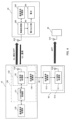
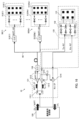
- FIG. 16 is a block diagram showing an example of the overall configuration of a system including a base station (aggregation station) 10 and multiple base stations 50(1) to 50(Nr) according to an embodiment.
- an input/output signal processing unit 131 constituting a wireless processing device (wireless processing unit) 130 of the base station (aggregation station) 10 includes a signal separation unit 1311, a first mixer 1312, a second mixer 1313, a third mixer 1314, and a local oscillator 1315.
- the signal separation unit 1311 separates the downlink intermediate frequency signal (baseband signal) output from the communication signal processing unit 120 into an intermediate frequency signal of the WPT dummy signal (WPT-IT) and an intermediate frequency signal of the DL communication signal (DL-IF).
- the first mixer 1312 generates a WPT dummy RF signal (WPT-RF) by mixing the intermediate frequency signal (WPT-IT) of the WPT dummy signal with a local oscillation signal (LO) of a predetermined frequency output from a local oscillator 1315.
- WPT-RF WPT dummy RF signal
- the WPT dummy RF signal (WPT-RF) is converted to an optical signal by a transmission signal conversion unit (E/O converter) 134 and transmitted to each of the multiple (Nr) base stations 50(1) to 50(Nr) via a signal transmission line (optical fiber) 60.
- the optical signal received via the signal transmission line (optical fiber) 60 is converted into an electrical WPT dummy RF signal (WPT-RF) by the transmission signal conversion unit (O/E converter) 513(1) to 513(Nr), and is then supplied to an antenna system 512(1) to 512(Nr) having an array antenna.
- WPT-RF transmission signal conversion unit
- the second mixer 1313 in the input/output signal processing unit 131 constituting the radio processing device (radio processing unit) 130 of the base station (aggregator) 10 mixes the intermediate frequency signal (DL-IF) of the DL communication signal with a local oscillation signal (LO) of a predetermined frequency output from the local oscillator 1315 to generate a DL communication RF signal (Tx-RF).
- the DL communication RF signal (Tx-RF) is supplied to the RF signal processing unit 132 provided in the antenna system 133 via an RF signal line.
- the third mixer 1314 in the input/output signal processing unit 131 mixes the UL communication RF signal (Rx-RF) input from the RF signal processing unit 132 of the antenna system 133 via the RF signal line with a local oscillation signal (LO) of a predetermined frequency output from the local oscillator 1315 to generate an intermediate frequency signal (UL-IF) of the UL communication signal, and outputs it to the communication signal processing unit 120.
- UL-RF UL communication RF signal
- LO local oscillation signal
- UL-IF intermediate frequency signal
- FIG. 17 is a block diagram showing another example of the overall configuration of a system including a base station (aggregation station) 10 and multiple base stations 50(1) to 50(Nr) according to an embodiment.
- an input/output signal processing unit 131 constituting a wireless processing device (wireless processing unit) 130 of the base station (aggregation station) 10 includes an isolator 1316, a signal separation unit 1311, a termination unit 1317, a first mixer 1312, a second mixer 1313, a third mixer 1314, and a local oscillator 1315.
- the signal separation unit 1311 separates the first branch signal, which is a downlink intermediate frequency signal (baseband signal) that is output from the communication signal processing unit 120, branched, and passed through the isolator 1316, into an intermediate frequency signal of a WPT dummy signal (WPT-IT) and an intermediate frequency signal of a DL communication signal (DL-IF).
- the intermediate frequency signal of the DL communication signal (DL-IF) is terminated in the termination unit 1317.
- the first mixer 1312 generates a WPT dummy RF signal (WPT-RF) by mixing the intermediate frequency signal (WPT-IT) of the WPT dummy signal with a local oscillation signal (LO) of a predetermined frequency output from a local oscillator 1315.
- WPT-RF WPT dummy RF signal
- the WPT dummy RF signal (WPT-RF) is converted to an optical signal by a transmission signal conversion unit (E/O converter) 134 and transmitted to each of the multiple (Nr) base stations 50(1) to 50(Nr) via a signal transmission line (optical fiber) 60.
- the optical signal received via the signal transmission line (optical fiber) 60 is converted into an electrical WPT dummy RF signal (WPT-RF) by the transmission signal conversion unit (O/E converter) 513(1) to 513(Nr), and is then supplied to an antenna system 512(1) to 512(Nr) having an array antenna.
- WPT-RF transmission signal conversion unit
- the second mixer 1313 in the input/output signal processing unit 131 constituting the radio processing device (radio processing unit) 130 of the base station (aggregator) 10 mixes a second branch signal (Tx-IF), which is a downlink intermediate frequency signal (baseband signal) output from the communication signal processing unit 120 and branched, with a local oscillation signal (LO) of a predetermined frequency output from a local oscillator 1315, to generate a DL communication RF signal (Tx-RF).
- Tx-IF is a downlink intermediate frequency signal (baseband signal) output from the communication signal processing unit 120 and branched
- LO local oscillation signal
- Tx-RF DL communication RF signal
- the DL communication RF signal (Tx-RF) is supplied to an RF signal processing unit 132 provided in an antenna system 133 via an RF signal line.
- the third mixer 1314 in the input/output signal processing unit 131 mixes the UL communication RF signal (Rx-RF) input from the RF signal processing unit 132 of the antenna system 133 via the RF signal line with a local oscillation signal (LO) of a specific frequency output from the local oscillator 1315 to generate an intermediate frequency signal (UL-IF) of the UL communication signal, and outputs it to the communication signal processing unit 120.
- UL-RF UL communication RF signal
- LO local oscillation signal
- UL-IF intermediate frequency signal
- wireless resources unused for communication can be effectively utilized as wireless power transmission blocks (WPT blocks), and wireless power transmission (WPT) can be performed from the base station (aggregation station) 10 and the base station 50 to the UE 20.
- WPT wireless power transmission blocks
- the WPT areas 11A, 51A where wireless power can be transmitted from the base station 10 can be expanded so as to approach the communication area 10A.
- each of the multiple base stations 50 may perform beamforming control independent of each other and perform wireless power transmission individually to each of the multiple UEs 20.
- the base station 50 may capture images of the surrounding area of the base station using an imaging device such as a camera, and obtain location information of the UEs 20 based on the captured images (still images or video images).
- FIG. 18 is an explanatory diagram showing an example of power supply to each UE by beamforming from the base station (aggregation station) 10 and base station 50 according to this embodiment to multiple UEs 20.
- the base station device 100 of the base station (aggregation station) 10 may supply power to each UE 20(1) to 20(3) via beams 10B(1) to 10B(3) formed for each UE.
- the beams 10B(1) to 10B(3) may be formed by switching in a time division manner, for example.
- base station 50 may supply power to each of UEs 20(4)-20(6) via beams 50B(1)-50B(3) formed for each UE.
- Beams 10B(1)-10B(3) may be formed by switching between them in a time-division manner, for example.
- the WPT areas 11A and 51A in which wireless power can be transmitted from the base station 10 can be expanded so as to approach the communication area 10A.
- the base station 10 can amplify the communication signal in a low output power range with a large margin so that spurious signals are not generated, and can achieve high output and high efficiency for the power amplifier when amplifying the WPT dummy signal.
- the present invention can provide a power supply infrastructure that can supply power to a large number of terminal devices 20 that can receive radio waves transmitted from a base station 10, thereby contributing to the achievement of Goal 9 of the Sustainable Development Goals (SDGs), which is to "build resilient infrastructure, promote inclusive and sustainable industrialization, and promote innovation and infrastructure.”
- SDGs Sustainable Development Goals
- processing steps described in this specification and the components of the system, radio processing device, terminal device (UE, IoT device), base station, aggregation station, base station, mobile station, relay device, and control device can be implemented by various means.
- these steps and components may be implemented by hardware, firmware, software, or a combination thereof.
- the processing units and other means used to realize the above steps and components in an entity may be implemented in one or more application specific integrated circuits (ASICs), digital signal processors (DSPs), digital signal processors (DSPDs), programmable logic devices (PLDs), field programmable gate arrays (FPGAs), processors, controllers, microcontrollers, microprocessors, electronic devices, other electronic units designed to perform the functions described herein, computers, or combinations thereof.
- ASICs application specific integrated circuits
- DSPs digital signal processors
- DSPDs digital signal processors
- PLDs programmable logic devices
- FPGAs field programmable gate arrays
- processors controllers, microcontrollers, microprocessors, electronic devices, other electronic units designed to perform the functions described herein, computers, or combinations thereof.
- the means such as processing units used to realize the above components may be implemented with programs (e.g., code such as procedures, functions, modules, instructions, etc.) that perform the functions described herein.
- programs e.g., code such as procedures, functions, modules, instructions, etc.
- any computer/processor readable medium tangibly embodying firmware and/or software code may be used to implement the means such as processing units used to realize the above steps and components described herein.
- the firmware and/or software code may be stored in a memory and executed by a computer or processor, for example in a control device.
- the memory may be implemented within the computer or processor or external to the processor.
- the firmware and/or software code may also be stored in a computer or processor readable medium, such as, for example, random access memory (RAM), read-only memory (ROM), non-volatile random access memory (NVRAM), programmable read-only memory (PROM), electrically erasable programmable read-only memory (EEPROM), flash memory, floppy disks, compact disks (CDs), digital versatile disks (DVDs), magnetic or optical data storage devices, etc.
- RAM random access memory
- ROM read-only memory
- NVRAM non-volatile random access memory
- PROM programmable read-only memory
- EEPROM electrically erasable programmable read-only memory
- flash memory floppy disks, compact disks (CDs), digital versatile disks (DVDs), magnetic or optical data storage devices, etc.
- CDs compact disks
- DVDs digital versatile disks
- magnetic or optical data storage devices etc.
- the code may be executed by one or more computers or processors and may cause the computers or processors to
- the medium may also be a non-transitory recording medium.
- the program code may be in any format as long as it can be read and executed by a computer, processor, or other device or machine, and the format is not limited to a specific format.
- the program code may be any of source code, object code, and binary code, or may be a mixture of two or more of these codes.
Landscapes
- Engineering & Computer Science (AREA)
- Computer Networks & Wireless Communication (AREA)
- Power Engineering (AREA)
- Signal Processing (AREA)
- Mobile Radio Communication Systems (AREA)
Abstract
基地局(10)からの無線電力伝送可能なエリアを通信可能エリアに近づけるように拡大することができるアンテナシステムを提供する。アンテナシステムは、通信及び無線電力伝送に兼用される第1アレーアンテナ(110)と、第1アレーアンテナを中心としたエリア(10A)に第1アレーアンテナから離して分散配置された複数の無線電力伝送専用の第2アレーアンテナ(510)と、を備える。前記アンテナシステムは、第1のアレーアンテナの複数のアンテナ素子(1101)のそれぞれに接続された複数の第1無線信号処理ユニット(1320)と、複数の第2アレーアンテナのそれぞれに対して設けられ、第2アレーアンテナの複数のアンテナ素子(5101)のそれぞれに接続された複数の第2無線信号処理ユニット(5110)と、を更に備えてもよい。
Description
本発明は、通信及び無線電力伝送(WPT)を行うことができるシステム、無線処理装置及びアンテナシステムに関するものである。
従来、無線フレームに設定された複数の無線リソースの少なくとも一部を用いて基地局と端末装置との間で通信を行う通信システムが知られている(例えば、特許文献1参照)。
従来の通信システムにおいて基地局に接続して通信する端末装置として、内蔵電池から供給される電力を主に利用する携帯型の端末装置がある。この端末装置では、内蔵電池の残量が少なくなったときに内蔵電池を充電する煩雑な作業が必要である。また、内蔵電池ではなく有線接続の電源ラインから供給される電力を利用する端末装置は、そのような電源ラインを利用可能な場所での使用に制限される。このように基地局に接続して通信を行う様々な端末装置への給電をまかなうことができるような給電インフラが未整備である。
第5世代及びその後の次世代の移動通信システムでは、基地局に接続して通信する端末装置(例えば、ユーザ装置、IoTデバイス等)が急増してくるのが予想され、膨大なトラフィックを捌く通信インフラの整備が進められている。しかしながら、上記通信を行う膨大な数の端末装置への給電をまかなうことができる給電インフラは未整備のままである。
上記端末装置へ給電する給電インフラとして、移動通信の基地局を用いて無線電力伝送(WPT)を行うシステムが検討されている。かかるシステムの課題の一つとして、無線電力伝送時に基地局から送信される電波の送信電力に制約があるため、基地局からの電波の電力を端末装置が受電できる無線電力伝送可能なエリアが、基地局が端末装置と通信することができる通信可能エリアよりも狭いことがある。
本発明の一態様に係るアンテナシステムは、移動通信システムの通信及び無線電力伝送に用いることができるアンテナシステムである。このアンテナシステムは、通信及び無線電力伝送に兼用される第1アレーアンテナと、前記第1アレーアンテナの周りのエリアに前記第1アレーアンテナから離して分散配置された複数の無線電力伝送専用の第2アレーアンテナと、を備える。
前記アンテナシステムにおいて、前記第1アレーアンテナの複数のアンテナ素子のそれぞれに接続され、下りリンクの無線電力伝送用のダミー信号、下りリンクの通信信号及び上りリンクの通信信号のそれぞれに対応する複数の高周波信号を互いに異なる増幅器で増幅し、前記アンテナ素子を介して、前記複数の高周波信号を多重化して送受信する複数の第1無線信号処理ユニットと、前記複数の第2アレーアンテナのそれぞれに対して設けられ、前記第2アレーアンテナの複数のアンテナ素子のそれぞれに接続され、下りリンクの無線電力伝送用のダミー信号に対応する高周波信号を増幅し、前記アンテナ素子を介して前記高周波信号を送信する複数の第2無線信号処理ユニットと、を備えてもよい。
前記アンテナシステムにおいて、前記複数の第1無線信号処理ユニットはそれぞれ、前記アンテナ素子から送信される前記無線電力伝送用のダミー信号の位相を制御するための第1移相器と、前記無線電力伝送用のダミー信号を増幅する第1増幅器と、前記アンテナ素子から送信される前記下りリンクの通信信号の位相を制御するための第2移相器と、前記下りリンクの通信信号を増幅する第2増幅器と、前記アンテナ素子を介して受信された前記上りリンクの通信信号を増幅する第3増幅器と、前記上りリンクの通信信号の位相を制御するための第3位相器と、を備えてもよい。ここで、前記第1増幅器は、バイアス調整型の高効率増幅器又は波形処理型の高効率増幅器であってもよく、前記第2増幅器は、線形領域での効率改善を行う増幅器であってもよく、前記第3増幅器は、低ノイズ増幅器であってもよい。
前記システムにおいて、前記複数の第2無線信号処理ユニットはそれぞれ、前記アンテナ素子から送信される前記無線電力伝送用のダミー信号の位相を制御するための第4移相器と、前記無線電力伝送用のダミー信号を増幅する第4増幅器と、を備えてもよい。ここで、前記第4増幅器は、バイアス調整型の高効率増幅器又は波形処理型の高効率増幅器であってもよい。
前記システムにおいて、前記複数の第1無線信号処理ユニットはそれぞれ、前記無線電力伝送用のダミー信号、前記下りリンクの通信信号及び前記上りリンクの通信信号を時分割複信(TDD)方式で多重化する多重化処理部を備えてもよい。ここで、前記無線電力伝送用のダミー信号に用いられる無線電力伝送用のフレーム、前記下りリンクの通信信号に用いられる下りリンク通信用のフレーム及び前記上りリンクの通信信号に用いられる上りリンク通信用のフレームが時分割されて通信フレームに割り当てられ、前記多重化処理部は、前記無線電力伝送用のフレーム、前記下りリンク通信用のフレーム及び前記上りリンク通信用のフレームに同期させて、前記無線電力伝送用のダミー信号、前記下りリンクの通信信号及び前記上りリンクの通信信号それぞれの信号処理経路と前記アンテナ素子との接続を切り替えてもよい。
前記システムにおいて、前記複数の第1無線信号処理ユニットはそれぞれ、前記無線電力伝送用のダミー信号、前記下りリンクの通信信号及び前記上りリンクの通信信号を周波数分割複信(FDD)方式で多重化する多重化処理部を備えてもよい。ここで、前記第1アレーアンテナは、前記無線電力伝送用のダミー信号の送信に用いられる無線電力伝送用のアレーアンテナと、前記下りリンクの通信信号の送信及び前記上りリンクの通信信号の受信に用いられる通信用のアレーアンテナと、を有し、前記複数の第1無線信号処理ユニットは、前記無線電力伝送用のアレーアンテナの複数のアンテナ素子のそれぞれに接続され、前記無線電力伝送用のダミー信号の高周波信号を無線電力伝送用の増幅器で増幅し、前記アンテナ素子を介して送信する複数の無線電力伝送用の無線信号処理ユニットと、前記通信用のアレーアンテナの複数のアンテナ素子のそれぞれに接続され、前記下りリンクの通信信号及び前記上りリンクの通信信号の複数の高周波信号を互いに異なる増幅器で増幅し、前記アンテナ素子を介して前記複数の高周波信号を多重化して送受信する複数の通信用の無線信号処理ユニットと、を有してもよい。
本発明の他の態様に係る無線処理装置は、前記いずれかのアンテナシステムと、前記複数の第1無線信号処理ユニットに接続され、信号伝送線を介して前記複数の第2無線信号処理ユニットに接続された入出力信号処理部と、を備える。前記入出力信号処理部は、前記無線電力伝送用のダミー信号及び前記下りリンクの通信信号を含む下りリンク中間周波信号を、前記無線電力伝送用のダミー信号の中間周波信号と前記下りリンクの通信信号の中間周波信号とに分離する信号分離部と、前記信号分離部で分離された前記無線電力伝送用のダミー信号の中間周波信号と所定周波数の局部発振信号とを混合して前記無線電力伝送用のダミー信号の高周波信号を生成する第1混合器と、前記下りリンクの通信信号の中間周波信号と前記局部発振信号とを混合して前記下りリンクの通信信号の高周波信号を生成する第2混合器と、前記上りリンクの通信信号の高周波信号と前記局部発振信号とを混合して前記上りリンクの通信信号の中間周波信号を生成する第3混合器と、を有する。
本発明の他の態様に係る無線処理装置は、前記いずれかのアンテナシステムと、前記複数の第1無線信号処理ユニットに接続され、信号伝送線を介して前記複数の第2無線信号処理ユニットに接続された入出力信号処理部と、を備える。前記入出力信号処理部は、前記無線電力伝送用のダミー信号及び前記下りリンクの通信信号を含む下りリンク中間周波信号を分岐した第1分岐信号を、前記無線電力伝送用のダミー信号の中間周波信号と前記下りリンクの通信信号の中間周波信号とに分離する信号分離部と、前記信号分離部で分離された前記無線電力伝送用のダミー信号の中間周波信号と所定周波数の局部発振信号とを混合して前記無線電力伝送用のダミー信号の高周波信号を生成する第1混合器と、前記信号分離部で分離された前記下りリンクの通信信号の中間周波信号を終端する終端部と、前記無線電力伝送用のダミー信号及び前記下りリンクの通信信号を含む下りリンク中間周波信号を分岐した第2分岐信号と、前記局部発振信号とを混合して前記下りリンクの通信信号の高周波信号を生成する第2混合器と、前記上りリンクの通信信号の高周波信号と前記局部発振信号とを混合して前記上りリンクの通信信号の中間周波信号を生成する第3混合器と、を有する。ここで、前記入出力信号処理部は、前記第1分岐信号を一方向に通過させて前記信号分離部に伝送するアイソレータを更に有してもよい。
本発明の更に他の態様に係るシステムは、移動通信システムの端末装置に無線電力伝送を行うシステムである。このシステムは、前記いずれかの無線処理装置と、前記無線電力伝送用のダミー信号及び前記下りリンクの通信信号を含む下りリンク中間周波信号を生成し、前記上りリンクの通信信号を含む上りリンク中間周波信号を処理する通信信号処理部と、を備える。
前記システムにおいて、前記第1アレーアンテナと前記複数の第1無線信号処理ユニットと前記入出力信号処理部とを有する集約局と、前記信号伝送線を介して前記集約局の前記入出力信号処理部に接続され、前記第1アレーアンテナと前記複数の第1無線信号処理ユニットとをそれぞれ有する複数の張出局と、を備えてもよい。
前記システムにおいて、前記複数の張出局は、互いに独立したビームフォーミング制御を行い、複数の端末装置のそれぞれに対して個別に無線電力伝送を行ってもよい。ここで、前記張出局は、周辺に位置する端末装置の位置情報を取得し、前記端末装置の位置情報に基づいて前記端末装置に対するビームフォーミング制御を行ってもよい。また、前記張出局は、自局の周辺を撮影し、撮影した画像に基づいて前記端末装置の位置情報を取得してもよい。
前記システムにおいて、前記集約局は、前記第1アレーアンテナと前記複数の第1無線信号処理ユニットとを有する遠隔無線ヘッド装置と、前記遠隔無線ヘッド装置から離れた位置に配置され、信号伝送線を介して前記遠隔無線ヘッド装置に接続された、前記通信信号処理部を有するベースバンドユニット装置と、を備えてよい。
前記システムにおいて、前記無線処理装置の前記第1アレーアンテナ又は前記第2アレーアンテナを介して無線電力伝送可能な端末装置を備え、前記端末装置は、前記無線処理装置から送信された前記無線電力伝送用のダミー信号を含む送信信号を受信する無線処理部と、前記無線電力伝送用のダミー信号を含む送信信号を受信した受信信号の電力を、受電電力として出力する電力出力部と、を有してもよい。
本発明によれば、基地局からの無線電力伝送可能なエリアを通信可能エリアに近づけるように拡大することができる。
以下、図面を参照して本発明の実施形態について説明する。
本書に記載された実施形態に係るシステムは、移動通信の基地局から給電対象の端末装置(例えば、移動通信のUE(移動局)やIoTデバイス)に対して無線電力伝送(WPT)することができるシステムである。実施形態のシステムは、例えば、UEなどの端末装置への下りリンクの無線フレームに設定された複数の無線リソース(リソースブロック)のうち通信に使用されていない通信未使用の無線リソース(リソースブロック)を端末装置への無線電力伝送(WPT)に有効活用したシステムである。実施形態のシステムは、基地局から端末装置への無線電力伝送(WPT)機能を有する、基地局と端末装置との間の無線通信システムであってもよい。また、実施形態のシステムは、基地局と端末装置との間の無線通信機能を有する、基地局から端末装置への無線電力伝送(WPT)システムであってもよい。
本書に記載された実施形態に係るシステムは、移動通信の基地局から給電対象の端末装置(例えば、移動通信のUE(移動局)やIoTデバイス)に対して無線電力伝送(WPT)することができるシステムである。実施形態のシステムは、例えば、UEなどの端末装置への下りリンクの無線フレームに設定された複数の無線リソース(リソースブロック)のうち通信に使用されていない通信未使用の無線リソース(リソースブロック)を端末装置への無線電力伝送(WPT)に有効活用したシステムである。実施形態のシステムは、基地局から端末装置への無線電力伝送(WPT)機能を有する、基地局と端末装置との間の無線通信システムであってもよい。また、実施形態のシステムは、基地局と端末装置との間の無線通信機能を有する、基地局から端末装置への無線電力伝送(WPT)システムであってもよい。
特に、本実施形態のシステムでは、基地局から送信する無線電力伝送用の送信信号を、集約局の通信・WPTアンテナ(第1アレーアンテナ)から送信するとともに、通信・WPTアンテナを中心としたエリアに通信・WPTアンテナから離して分散配置された複数の張出局の無線電力伝送専用のWPTアンテナ(第2アレーアンテナ)から送信できるため、基地局からの無線電力伝送可能なエリアを通信可能エリア(以下「通信エリア」ともいう。)に近づけるように拡大することができる。
図1は、実施形態に係るシステムの概略構成の一例を示す説明図である。本実施形態のシステムは、通信エリア(セル)10A及び無線電力伝送エリア(以下「WPTエリア」ともいう。)11Aを形成するセルラー方式の基地局(以下「集約局」ともいう。)10と、信号伝送線60を介して基地局(集約局)10に接続された複数の張出局50とを有する。システムは、通信エリア10Aに在圏しているときに基地局10に接続して基地局10と無線通信可能な給電対象の端末装置(以下「UE」(ユーザ装置)ともいう。)20、を含んでもよい。
UE20は、移動通信システムの移動局でもよいし、通信装置(例えば移動通信モジュール)と各種デバイスとを組み合わせたものであってもよい。UE20は、例えば複数のアンテナ素子を有するアレーアンテナを備える。UE20はIoTデバイス(「IoT機器」ともいう。)であってもよい。
図1において、基地局10は、多数のアンテナ素子を有する複数のアレーアンテナ110を備え、複数のUE20との間でmassive MIMO(以下「mMIMO」ともいう。)伝送方式の通信を行うことができる。mMIMOは、アレーアンテナ110を用いてデータ送受信を行うことにより大容量・高速通信を実現する無線伝送技術である。また、基地局10は、複数のUE20のそれぞれに対して時分割で又は同時にビーム10Bを形成するビームフォーミングを行うMU(Multi User)-MIMO伝送方式で通信を行うことができる。多素子のアレーアンテナを用いてMU-MIMO伝送を行うことにより、各UE20の通信環境に応じてUE20ごとに適切なビームを向けて通信できるため、セル全体の通信品質を改善できる。また、同一の無線リソース(時間・周波数リソース)を用いて複数のUE20との通信ができるため、システム容量を拡大することができる。
図2に示すように、基地局(集約局)10の通信及び無線電力伝送に兼用される第1アレーアンテナとしてのアレーアンテナ110を中心とした通信エリア10A内の中央部は、基地局10からUE20に向けて直接的に無線電力伝送を行うWPTエリア11Aになっている。しかしながら、法律などの規制により基地局10からの無線電力伝送時の電波の送信電力を十分に高めることができず、基地局10から離れた遠方では、基地局(集約局)10からの無線電力伝送の電波を受電することができないため、WPTエリア11Aは図示のように通信エリア10Aよりも狭いエリアである。
そこで、本実施形態のシステムでは、図3に示すように、通信エリア10Aのうち基地局(集約局)10のWPTエリア11Aでカバーしきれないエリアに、基地局10のアレーアンテナ110から離して分散配置された複数の無線電力伝送専用の第2アレーアンテナとしての複数の張出局50(1)~50(6)のアレーアンテナ510(1)~510(6)を備えている。
基地局10から信号伝送線60及び複数の張出局50(1)~50(6)のアレーアンテナ510(1)~510(6)を介してWPTエリア51A(1)~51A(6)を形成することにより、基地局10のWPTエリア11Aを、通信エリア10Aと同等なエリアサイズまで実質的に拡大させている。なお、図3の例では、張出局50(1)~50(6)のアレーアンテナ510(1)~510(6)の数が6の場合について例示しているが、張出局50及びアレーアンテナ510の数は2~5でもよいし、7以上であってもよい。
基地局10から信号伝送線60及び複数の張出局50(1)~50(6)のアレーアンテナ510(1)~510(6)を介してWPTエリア51A(1)~51A(6)を形成することにより、基地局10のWPTエリア11Aを、通信エリア10Aと同等なエリアサイズまで実質的に拡大させている。なお、図3の例では、張出局50(1)~50(6)のアレーアンテナ510(1)~510(6)の数が6の場合について例示しているが、張出局50及びアレーアンテナ510の数は2~5でもよいし、7以上であってもよい。
WPTエリア11A,51Aではそれぞれ、基地局10からの下りリンクの無線フレームを構成する複数の無線リソース(時間・周波数リソース)であるリソースブロックのうち通信に用いられていない通信未使用の無線リソース(リソースブロック)を無線電力伝送ブロックとして活用している。基地局10は、UE20への下りリンクの無線フレームにおいて、通信未使用の無線リソースである無線電力伝送ブロック(WPTブロック)に無線電力伝送用のダミー信号(以下「WPTダミー信号」ともいう。)を割り当てた送信信号を生成してWPTエリア11A内のUE20に送信するとともに、信号伝送線60を介して張出局50(1)~50(6)のそれぞれに送信する。張出局50(1)~50(6)はそれぞれ、基地局10から受信した送信信号をWPTエリア51A内のUE20に送信する。
特に、第5世代又はそれ以降の世代の移動通信システムにおいては、無線フレームの一部のサブキャリアのみに必要最小限の参照信号(RS)や制御信号を配置するリーンキャリアという技術が提案されており、無線フレームにおける通信未使用の無線リソースの部分を有効活用してUE20への無線電力伝送を行うことが期待される。
基地局10とUE20との間で送受信される通信の信号の電波及び基地局10からUE20に送信されるWPTダミー信号を割り当てた送信信号の電波は、例えば、ミリ波又はマイクロ波である。
図4は、実施形態に係るシステムを構成する基地局(集約局)10、張出局50及び端末装置(UE)20の主要構成の一例を示すブロック図である。基地局10は、アンテナ110と通信信号処理部120と無線処理装置(無線処理部)130とを備える。
なお、図4の基地局10において、無線処理装置130を有する遠隔無線ヘッド装置(RRH)と、通信信号処理部120を有するベースバンドユニット(BBU)装置と、を備えてもよい。ベースバンドユニット(BBU)装置は、遠隔無線ヘッド装置(RRH)から離れた位置に配置され、有線の通信回線(例えば光ファイバーからなる光回線)を介して遠隔無線ヘッド装置に接続される。
アンテナ110は、例えば、図1に示すように多数のアンテナ素子を有するアレーアンテナである。アンテナ110は単数でもよいし複数であってもよい。例えば、アンテナ110は複数のセクタセルに対応させて複数配置してもよい。
通信信号処理部120は、例えばFPGA(Field Programmable Gate Array)で構成され、UE20との間で送受信される各種のユーザデータや制御情報等の信号を処理する。
通信信号処理部120は、UE20に対する下りリンクの通信の際に、複数の無線リソースのうち通信に使用されていない通信未使用の無線リソースを用いたWPTダミー信号を含む下りリンクの送信信号を生成する。例えば、WPTダミー信号は、通信信号よりもPAPR(ピーク電力対平均電力比)(「波高比」ともいう。)が小さい変調方式で変調して生成することができる。例えば、WPTダミー信号は、Zadoff-Chu系列の符号を用いて変調され、時間に対して振幅が一定で位相が変化する変調信号であってもよく、また、デジタル変調方式の複数のシンボル点のうち振幅が最大又は最大近傍の複数のシンボル点で変調された信号であってもよい。また例えば、送信信号の生成は、通信信号用のQAM(直交振幅変調)やWPTダミー信号用のPAPRが小さい変調等の一次変調、並びに、OFDM(直交周波数多重)変調等の二次変調を含んでもよい。
無線処理装置130は、通信信号処理部120で生成した送信信号をアンテナ110からUE20に送信したり、UE20からアンテナ110を介して受信した受信信号を通信信号処理部120に出力したり、WPTダミー信号の高周波の無線信号(RF信号)を張出局50に送信したりする。
UE20に対する下りリンク通信の送信信号に通信未使用の無線リソースを用いたWPTダミー信号を含める処理や、後述の信号の分離や信号の合成等に用いる制御信号(トリガー信号)の生成は、移動通信の無線フレームを構成するサブフレームに基づいて行ってもよい。
また、UE20に対する下りリンク通信の送信信号に、通信未使用の無線リソースを用いたWPTダミー信号を含める処理は、基地局10が自律的に行ってもよいし、UE20からの要求若しくは指示又は外部プラットフォーム(例えば、サーバ、クラウドシステム)からの要求若しくは指示に基づいて行ってもよい。
また、本実施形態において、無線処理装置130は、BF制御信号に基づいてアレーアンテナ110で形成される一又は複数のビームを制御する。また、無線処理装置130は、通信信号処理部120で生成されたWPTダミー信号を含む下りリンクの送信信号を、アンテナ110を介してUE20に送信する。
基地局10は、UE20に対する下りリンクの通信の際に、UE20毎に又は複数のUE20が属するターゲットエリアのUEグループ毎に、個別のビーム10Bを形成するビームフォーミング(BF)制御を行い、UE20毎に又はUEグループ毎に無線電力伝送を行ってもよい。UE20毎又はUEグループ毎のBF制御は、通信信号処理部120における周波数領域のデジタルBF制御で行ってもよいし、無線処理装置130におけるアナログBF制御で行ってもよい。
図4において、無線処理装置130は、入出力信号処理部131と、無線信号処理部(以下、「RF信号処理部」ともいう。)132及びアンテナ110を有するアンテナシステム133と、伝送信号変換部134とを備える。伝送信号変換部134は、張出局50に向けて送信するWPTダミー信号のRF信号(WPTダミーRF信号)を、信号伝送線60で伝送可能な伝送信号に変換する。例えば、信号伝送線60として、RoF(Radio over Fiber)技術を適用可能な光ファイバーを用いる場合、伝送信号変換部134は、WPTダミーRF信号の電気信号を光信号(伝送信号)に変換するE/O(電気信号/光信号)変換器を用いることができる。
図4において、張出局50は、無線信号処理部(以下、「RF信号処理部」ともいう。)511及びアンテナ510を有するアンテナシステム512と、伝送信号変換部513とを備える。RF信号処理部511は、アンテナ510の各アンテナ素子に供給するWPTダミーRF信号の位相を所定の位相に制御することにより、アンテナ510を介したビームフォーミング制御を行ってWPTダミーRF信号を送信する。伝送信号変換部513は、信号伝送線60を介して基地局(集約局)10から受信した伝送信号を、RF信号処理部511で処理可能なWPTダミーRF信号に変換する。例えば、信号伝送線60として、RoF技術を適用可能な光ファイバーを用いる場合、伝送信号変換部513は、光信号(伝送信号)をWPTダミーRF信号の電気信号に変換するO/E(光信号/電気信号)変換器を用いることができる。
図4において、UE20は、アンテナ210と無線処理部220と通信信号処理部230と電力出力部240と電池250とを含む。アンテナ210は、例えば複数のアンテナ素子を有する小型のアレーアンテナである。無線処理部220は、通信信号処理部230で生成したフィードバック情報やユーザデータ等の送信信号をアンテナ210から基地局10に送信したり、基地局10からアンテナ210を介して受信した受信信号を通信信号処理部230に出力したりする。
本実施形態において、無線処理部220は、基地局(集約局)10又は張出局50から送信されたWPTダミー信号を含む送信信号(WPTダミーRF信号)を受信する。また、電力出力部240は、例えば整流器を有し、基地局(集約局)10又は張出局50からのWPTダミー信号を含む送信信号(WPTダミーRF信号)を受信した受信信号の電力を、電池充電用の受電電力として出力する。電力出力部240から出力された受電電力により、電池250を充電することができる。
図5Aは、本実施形態に係る基地局10から送信される通信信号のQAM方式の一次変調におけるシンボル点41の配置の一例を示す説明図である。図5Aは、64QAM方式の場合の複数のシンボル点(64値のシンボル点)の配置を示すコンスタレーションの図である。また、図5Bは、本実施形態に係る基地局10から送信されるWPTダミー信号の変調におけるシンボル点の配置の一例を示す説明図である。図5A及び図5Bにおいて、横軸は同相チャネル成分を示し,縦軸は直交チャネル成分を示している。
本実施形態では、WPTダミー信号として、PAPR(ピーク電力対平均電力比)が通信信号よりも低いOFDM変調信号を用いる。例えば、図5Aにおいて、通信信号用のQAM方式の複数のシンボル点41のうち、振幅が最大である最外周又は最外周周辺の複数のシンボル点41Sのみで変調されたOFDM変調信号からなるWPTダミー信号を用いてもよい。
また、図5Bのコンスタレーション図に示すように、時間に対して振幅が一定の条件で位相が変化するシンボル点42で変調されたOFDM変調信号からなるWPTダミー信号を用いてもよい。図5Bのシンボル点42でOFDM変調信号は、例えばZadoff-Chu系列の符号を用いて生成することができる。
図6は、本実施形態に係る基地局10の増幅器の入力電力Pin[dBm]に対する出力電力Pout[dBm]及びアンプ効率PAE[%]の特性の一例を示すグラフである。図中の曲線Aは、増幅器の交流の入力電力Pin[dBm]に対する交流の出力電力Pout[dBm]を示す入出力特性のシミュレーション計算結果である。また、図中の破線の曲線B,C,Dはそれぞれ、上りリンク(UL)通信信号、下りリンク(DL)通信信号及びWPTダミー信号に適した増幅器の入力電力Pin[dBm]に対する効率の指標値の一つであるPAE(電力付加効率)[%]のシミュレーション計算結果である。ここで、増幅器のPAE[%]は、(Pout-Pin)/Pdcで定義される。Pdcは増幅器に入力(印加)される直流電力である。
図6の入出力特性Aにおいて、入力電力Pinと出力電力Poutとの関係が線形又はほぼ線形の関係にある領域は、UL通信信号の低ノイズ増幅及びDL通信信号の電力増幅に適する。特に、UL通信信号の増幅に適する増幅器の特性としては、例えば、高PAPR(ピーク電力対平均電力比)、高リニアリティ、広ダナミックレンジ及び低ノイズが要求される。また、DL通信信号の増幅に適する電力増幅器の特性としては、例えば、高PAPR、高リニアリティ及び広ダナミックレンジが要求される。この電力増幅器としては、例えば、ドハティ増幅器、エンベロープトラッキング増幅器、アウトフェージング増幅器などの線形領域での効率改善を行う増幅器が挙げられる。
である。
である。
また、図6の入出力特性Aの飽和領域は、入力電力Pinの増加に対して出力電力Poutが飽和又はほぼ飽和している領域である。線形領域と飽和領域の境界の近傍の領域に、電力増幅器の効率PAEのピークが位置し、この領域は、WPTダミー信号の高出力及び高効率の電力増幅に適する。WPTダミー信号の増幅に適する電力増幅器の特性としては、例えば、高効率、低PAPR及び大出力電力が要求される。この電力増幅器としては、例えば、A級増幅器、B級増幅器、C級増幅器、AB級増幅器などのバイアス調整型の高効率増幅器、又は、E級増幅器、F級増幅器、J級増幅器などの波形処理型の高効率増幅器が挙げられる。WPTダミー信号として、PAPR(ピーク電力対平均電力比)が通信信号よりも低いOFDM変調信号を用いてもよい。
上記構成の基地局(集約局)10又は張出局50において、WPTダミー信号、DL通信信号及びUL通信信号をそれぞれ、各信号に適した増幅器で増幅してもよい。例えば、以下に例示するように、基地局(集約局)10又は張出局50のアンテナシステム133において、WPTダミー信号、DL通信信号及びUL通信信号それぞれに対応する複数の信号処理パスを構成し、複数の信号処理パスのそれぞれに各信号に適した個別の増幅器を設けてもよい。
図7は、実施形態に係る張出局50に適用可能なアンテナシステムの構成の一例を示すブロック図である。図7において、アンテナシステム512は、複数(Nw個)のアンテナ素子5101(1)~5101(Nw)からなる無線電力伝送(WPT)用のアレーアンテナ(WPTアレーアンテナ)510と、WPTアレーアンテナ510に接続された無線電力伝送(WPT)用のRF信号処理部511とを備える。
無線電力伝送(WPT)用のRF信号処理部511は、アレーアンテナ510の複数(Nw個)のアンテナ素子5101(1)~5101(Nw)に1対1で対応する複数(Nw個)の無線信号処理ユニット(以下「WPTダミーRF信号処理ユニット」ともいう。)5110(1)~5110(Nw)を有する。複数のWPTダミーRF信号処理ユニット5110(1)~5110(Nw)はそれぞれ、対応するアンテナ素子5101(1)~5101(Nw)に接続される。また、WPTダミーRF信号処理ユニット5110(1)~5110(Nw)はそれぞれ、WPTダミーRF信号の位相を所定の位相に制御することにより、アンテナ素子5101(1)~5101(Nw)を介したビームフォーミング制御を行ってWPTダミーRF信号を送信する。
図8は、実施形態に係る基地局(集約局)10に適用可能なアンテナシステム133の構成の一例を示すブロック図である。図8において、アンテナシステム133は、複数(N個)のアンテナ素子1101(1)~1101(N)からなるアレーアンテナ110と、アレーアンテナ110に接続されたTDD(時分割複信)方式のRF信号処理部132とを備える。
RF信号処理部132は、アレーアンテナ110の複数(N個)のアンテナ素子1101(1)~1101(N)に1対1で対応する複数(N個)の無線信号処理ユニット(以下「RF信号処理ユニット」ともいう。)1320(1)~1320(N)を有する。複数のRF信号処理ユニット1320(1)~1320(N)はそれぞれ、対応するアンテナ素子1101(1)~1101(N)に接続され、下りリンクのWPTダミー信号及びDL通信信号並びに上りリンクのUL通信信号の高周波の送信信号であるWPTダミーRF信号、DL通信RF信号及びUL通信RF信号を互いに異なる複数の増幅器で増幅し、TDD(時分割複信)方式で多重化する。また、RF信号処理ユニット1320(1)~1320(N)はそれぞれ、WPTダミーRF信号、DL通信RF信号及びUL通信RF信号の位相を所定の位相に制御することにより、アンテナ素子1101(1)~1101(N)を介したビームフォーミング制御を行って各信号を送受信する。
図9は、図8のアンテナシステム133を構成するRF信号処理ユニット1320の構成の一例を示すブロック図である。なお、複数のRF信号処理ユニット1320(1)~1320(N)は同様な構成を有するので、図9では、括弧書きの識別番号を省略した一つのRF信号処理ユニット1320について説明する。
図9において、RF信号処理ユニット1320は、アンテナ素子1101から送信されるWPTダミーRF信号の位相を制御するための第1移相器1321Wと、WPTダミーRF信号を増幅する第1増幅器(電力増幅器)1322Wとを備える。更に、RF信号処理ユニット1320は、アンテナ素子1101から送信されるDL通信RF信号の位相を制御するための第2移相器1321Dと、DL通信RF信号を増幅する第2増幅器(電力増幅器)1322Dと、アンテナ素子1101を介して受信されたUL通信RF信号を増幅する第3増幅器(低ノイズ増幅器)1322Uと、UL通信RF信号の位相を制御するための第3位相器1321Uと、を備える。
また、RF信号処理ユニット1320は、WPTダミーRF信号、DL通信RF信号及びUL通信RF信号を時分割複信(TDD)方式で多重化する多重化処理部としての信号切替スイッチ1323を備える。信号切替スイッチ1323は、所定の制御信号に基づいて、WPTダミーRF信号、DL通信RF信号及びUL通信RF信号それぞれの信号処理パスとアンテナ素子1101との接続を切り替える。制御信号は、例えば、通信信号処理部120において所定のベースバンドのスケジューリング情報に基づいて生成してもよい。
図10は、図8のアンテナシステム133で送受信されるWPTダミー信号、DL通信信号及びUL通信信号のフレーム構成の一例を示す説明図である。図10中の「WPT」、「DL」及び「UL」を付した期間はそれぞれ、基地局10と端末装置20との間の無線通信のフレーム30に割り当てられた、WPTダミー信号を送信するWPT用フレーム32、DL通信信号を送信するDL通信用フレーム31D及びUL通信信号を受信するUL通信用フレーム31Uである。また、図10中のハッチングを付した期間は、信号の送受信を行わないガード期間である。
信号切替スイッチ1323は、図10に示すように、WPT用フレーム32、DL通信用フレーム31D及びUL通信用フレーム31Uに同期させて、WPTダミーRF信号、DL通信RF信号及びUL通信RF信号それぞれの増幅器1322W、1322D、1322Uを介した3つの信号処理経路とアンテナ素子1101との接続を切り替えてもよい。例えば、信号切替スイッチ1323の信号処理経路の切替により、WPT用フレーム32の期間において第1増幅器(電力増幅器)1322Wから出力されたWPTダミーRF信号がアンテナ素子1101に供給される。また、DL通信用フレーム31Dの期間において第2増幅器(電力増幅器)1322Dから出力されたDL通信RF信号がアンテナ素子1101に供給され、UL通信用フレーム31Uの期間においてアンテナ素子1101から出力されたUL通信RF信号が第3増幅器(低ノイズ増幅器)1322Uに供給される。
図11は、実施形態に係る基地局(集約局)10に適用可能なアンテナシステム133の構成の他の例を示すブロック図である。図11において、アンテナシステム133は、複数(N個)のアンテナ素子1101(1)~1101(N)からなるアレーアンテナ110と、アレーアンテナ110に接続されたFDD(周波数分割複信)方式のRF信号処理部132とを備える。
RF信号処理部132は、アレーアンテナ110の複数(N個)のアンテナ素子1101(1)~1101(N)に1対1で対応する複数(N個)の無線信号処理ユニット(RF信号処理ユニット)1325(1)~1325(N)を有する。複数のRF信号処理ユニット1325(1)~1325(N)はそれぞれ、対応するアンテナ素子1101(1)~1101(N)に接続され、WPTダミーRF信号、DL通信RF信号及びUL通信RF信号を互いに異なる複数の増幅器で増幅し、FDD(周波数分割複信)方式で多重化する。また、RF信号処理ユニット1325(1)~1325(N)はそれぞれ、WPTダミーRF信号、DL通信RF信号及びUL通信RF信号の位相を所定の位相に制御することにより、アンテナ素子1101(1)~1101(N)を介したビームフォーミング制御を行って各信号を送受信する。
図12は、図11のアンテナシステム133を構成するRF信号処理ユニット1325の構成の一例を示すブロック図である。なお、複数のRF信号処理ユニット1325(1)~1325(N)は同様な構成を有するので、図12では、括弧書きの識別番号を省略した一つのRF信号処理ユニット1325について説明する。
図12において、RF信号処理ユニット1325は、アンテナ素子1101から送信されるWPTダミーRF信号の位相を制御するための第1移相器1321Wと、WPTダミーRF信号を増幅する第1増幅器(電力増幅器)1322Wとを備える。更に、RF信号処理ユニット1325は、アンテナ素子1101から送信されるDL通信RF信号の位相を制御するための第2移相器1321Dと、DL通信RF信号を増幅する第2増幅器(電力増幅器)1322Dと、アンテナ素子1101を介して受信されたUL通信RF信号を増幅する第3増幅器(低ノイズ増幅器)1322Uと、UL通信RF信号の位相を制御するための第3位相器1321Uと、を備える。
また、RF信号処理ユニット1325は、WPTダミーRF信号、DL通信RF信号及びUL通信RF信号を周波数分割複信(FDD)方式で多重化する多重化処理部としてのアンテナ共用器(DUP:Duplexer)1326を備える。
アンテナ共用器1326は、例えば、第1増幅器(電力増幅器)1322Wの出力端に接続される送信フィルタ1327Wと、第2増幅器(電力増幅器)1322Dの出力端に接続される送信フィルタ1327Dと、第3増幅器(低ノイズ増幅器)1322Uの入力端に接続される受信フィルタ1327Uとを有する。送信フィルタ1327Wは、WPTダミーRF信号の周波数Fwを通過域とし、UL通信RF信号の周波数Fuを阻止域とするバンドパスフィルタ(BPF)である。送信フィルタ1327Dは、DL通信RF信号の周波数Fdを通過域とし、UL通信RF信号の周波数Fuを阻止域とするバンドパスフィルタ(BPF)である。受信フィルタ1327Uは、UL通信RF信号の周波数Fuを通過域とし、WPTダミーRF信号及びDL通信RF信号の周波数Fw、Fdを阻止域とするバンドパスフィルタ(BPF)である。アンテナ共用器1326の送信フィルタ1327W、1327Dの出力端及び受信フィルタ1327Uの入力端が移相器を介してアンテナ素子1101に接続される。
アンテナ共用器1326において、第1増幅器(電力増幅器)1322Wから出力された周波数FwのWPTダミーRF信号と第2増幅器(電力増幅器)1322Dから出力された周波数FdのDL通信RF信号は合成されてアンテナ素子1101に供給される。また、アンテナ素子1101から出力された周波数FuのUL通信RF信号は、第3増幅器(低ノイズ増幅器)1322Uに供給される。
図13は、実施形態に係る基地局(集約局)10に適用可能なセパレートアンテナ構成のアンテナシステム133の構成の一例を示すブロック図である。図13の構成例では、前述のアレーアンテナ110として、無線電力伝送(WPT)用のアレーアンテナ(以下「WPTアレーアンテナ」ともいう。)110W及び通信用のアレーアンテナ(以下「通信アレーアンテナ」ともいう。)110Cを別々に備えている。アンテナシステム133は、複数(Nw個)のアンテナ素子1101W(1)~1101W(Nw)からなるWPTアレーアンテナ110Wと、WPTアレーアンテナ110Wに接続された無線電力伝送(WPT)用のRF信号処理部132Wと、複数(Nc個)のアンテナ素子1101C(1)~1101C(Nc)からなる通信アレーアンテナ110Cと、通信アレーアンテナ110Cに接続された通信用のRF信号処理部132Cとを備える。
無線電力伝送(WPT)用のRF信号処理部132Wは、アレーアンテナ110の複数(Nw個)のアンテナ素子1101W(1)~1101W(Nw)に1対1で対応する複数(Nw個)の無線信号処理ユニット(以下「WPTダミーRF信号処理ユニット」ともいう。)1320W(1)~1320W(Nw)を有する。複数のWPTダミーRF信号処理ユニット1320W(1)~1320(Nw)はそれぞれ、対応するアンテナ素子1101W(1)~1101W(Nw)に接続される。また、WPTダミーRF信号処理ユニット1320W(1)~1320W(Nw)はそれぞれ、WPTダミーRF信号の位相を所定の位相に制御することにより、アンテナ素子1101W(1)~1101W(Nw)を介したビームフォーミング制御を行ってWPTダミーRF信号を送信する。
通信用のRF信号処理部132Cは、通信アレーアンテナ110Cの複数(Nc個)のアンテナ素子1101C(1)~1101C(Nc)に1対1で対応する複数(Nc個)の無線信号処理ユニット(以下「通信RF信号処理ユニット」ともいう。)1320C(1)~1320C(Nc)を有する。複数の通信RF信号処理ユニット1320C(1)~1320C(Nc)はそれぞれ、対応するアンテナ素子1101C(1)~1101C(Nc)に接続され、下りリンクのDL通信RF信号及びUL通信RF信号を互いに異なる複数の増幅器で増幅し、TDD(時分割複信)方式又はFDD(周波数分割複信)方式で多重化する。また、通信RF信号処理ユニット1320C(1)~1320C(Nc)はそれぞれ、DL通信RF信号及びUL通信RF信号の位相を所定の位相に制御することにより、アンテナ素子1101C(1)~1101C(Nc)を介したビームフォーミング制御を行って各信号を送受信する。
図14A及び図14Bはそれぞれ、図13のアンテナシステム133を構成する無線電力伝送(WPT)用のRF信号処理ユニット1320W及び通信用のRF信号処理ユニット1320Cの構成の一例を示すブロック図である。なお、複数のWPTダミーRF信号処理ユニット1320W及び通信RF信号処理ユニット1320Cはそれぞれ同様な構成を有するので、図14A及び図14Bでは、括弧書きの識別番号を省略したRF信号処理ユニット1320W,1320Cについて説明する。
図14Aにおいて、WPTダミーRF信号処理ユニット1320Wは、WPTアレーアンテナ110Wのアンテナ素子1101Wから送信されるWPTダミーRF信号の位相を制御するための第1移相器1321Wと、WPTダミーRF信号を増幅する第1増幅器(電力増幅器)1322Wとを備える。
図14Bにおいて、通信RF信号処理ユニット1320Cは、アンテナ素子1101Cから送信されるDL通信RF信号の位相を制御するための第2移相器1321Dと、DL通信RF信号を増幅する第2増幅器(電力増幅器)1322Dと、アンテナ素子1101Cを介して受信されたUL通信RF信号を増幅する第3増幅器(低ノイズ増幅器)1322Uと、UL通信RF信号の位相を制御するための第3位相器1321Uと、を備える。
また、通信RF信号処理ユニット1320Cは、DL通信RF信号及びUL通信RF信号を時分割複信(TDD)方式で多重化する多重化処理部としての信号切替スイッチ1328を備える。信号切替スイッチ1328は、所定の制御信号に基づいて、DL通信RF信号及びUL通信RF信号それぞれの信号処理パスとアンテナ素子1101Cとの接続を切り替える。制御信号は、例えば、通信信号処理部120において所定のベースバンドのスケジューリング情報に基づいて生成してもよい。
図15は、図13のアンテナシステム133を構成する通信RF信号処理ユニット1320Cの構成の他の例を示すブロック図である。なお、図15では、括弧書きの識別番号を省略した通信RF信号処理ユニット1320Cについて説明する。また、図15において、前述の図9の構成と同様な部分については、説明を省略する。
図15において、通信RF信号処理ユニット1320Cは、アンテナ素子1101Cから送信されるDL通信RF信号の位相を制御するための第2移相器1321Dと、DL通信RF信号を増幅する第2増幅器(電力増幅器)1322Dと、アンテナ素子1101Cを介して受信されたUL通信RF信号を増幅する第3増幅器(低ノイズ増幅器)1322Uと、UL通信RF信号の位相を制御するための第3位相器1321Uと、を備える。
また、通信RF信号処理ユニット1320Cは、DL通信RF信号及びUL通信RF信号を周波数分割複信(FDD)方式で多重化する多重化処理部としてのアンテナ共用器(DUP)1329を備える。アンテナ共用器1329において、第2増幅器(電力増幅器)1322Dから出力された周波数FdのDL通信RF信号はアンテナ素子1101Cに供給され、アンテナ素子1101Cから出力された周波数FuのUL通信RF信号は、第3増幅器(低ノイズ増幅器)1322Uに供給される。
図16は、実施形態に係る基地局(集約局)10及び複数の張出局50(1)~50(Nr)を含むシステムの全体構成の一例を示すブロック図である。図16において、基地局(集約局)10の無線処理装置(無線処理部)130を構成する入出力信号処理部131は、信号分離部1311と第1混合器1312と第2混合器1313と第3混合器1314と局部発振器1315とを備える。
信号分離部1311は、通信信号処理部120から出力された下りリンクの中間周波信号(ベースバンド信号)を、WPTダミー信号の中間周波信号(WPT-IT)とDL通信信号の中間周波信号(DL-IF)とに分離する。
第1混合器1312は、WPTダミー信号の中間周波信号(WPT-IT)と局部発振器1315から出力された所定周波数の局部発振信号(LO)とを混合してWPTダミーRF信号(WPT-RF)を生成する。WPTダミーRF信号(WPT-RF)は、伝送信号変換部(E/O変換器)134で光信号に変換され、信号伝送線(光ファイバー)60を介して複数(Nr)の張出局50(1)~50(Nr)のそれぞれに送信される。
複数の張出局50(1)~50(Nr)のそれぞれにおいて、信号伝送線(光ファイバー)60を介して受信された光信号は、伝送信号変換部(O/E変換器)513(1)~513(Nr)で電気信号のWPTダミーRF信号(WPT-RF)に変換され、アレーアンテナを有するアンテナシステム512(1)~512(Nr)に供給される。
基地局(集約局)10の無線処理装置(無線処理部)130を構成する入出力信号処理部131における第2混合器1313は、DL通信信号の中間周波信号(DL-IF)と局部発振器1315から出力された所定周波数の局部発振信号(LO)とを混合してDL通信RF信号(Tx-RF)を生成する。DL通信RF信号(Tx-RF)は、RF信号線を介して、アンテナシステム133に設けられたRF信号処理部132に供給される。
入出力信号処理部131における第3混合器1314は、アンテナシステム133のRF信号処理部132からRF信号線を介して入力されたUL通信RF信号(Rx-RF)と局部発振器1315から出力された所定周波数の局部発振信号(LO)とを混合してUL通信信号の中間周波信号(UL-IF)を生成し、通信信号処理部120に出力する。
図17は、実施形態に係る基地局(集約局)10及び複数の張出局50(1)~50(Nr)を含むシステムの全体構成の他の例を示すブロック図である。図17において、基地局(集約局)10の無線処理装置(無線処理部)130を構成する入出力信号処理部131は、アイソレータ1316と信号分離部1311と終端部1317と第1混合器1312と第2混合器1313と第3混合器1314と局部発振器1315とを備える。
信号分離部1311は、通信信号処理部120から出力されて分岐され、アイソレータ1316を通過した下りリンクの中間周波信号(ベースバンド信号)である第1分岐信号を、WPTダミー信号の中間周波信号(WPT-IT)とDL通信信号の中間周波信号(DL-IF)とに分離する。DL通信信号の中間周波信号(DL-IF)は、終端部1317で終端される。
第1混合器1312は、WPTダミー信号の中間周波信号(WPT-IT)と局部発振器1315から出力された所定周波数の局部発振信号(LO)とを混合してWPTダミーRF信号(WPT-RF)を生成する。WPTダミーRF信号(WPT-RF)は、伝送信号変換部(E/O変換器)134で光信号に変換され、信号伝送線(光ファイバー)60を介して複数(Nr)の張出局50(1)~50(Nr)のそれぞれに送信される。
複数の張出局50(1)~50(Nr)のそれぞれにおいて、信号伝送線(光ファイバー)60を介して受信された光信号は、伝送信号変換部(O/E変換器)513(1)~513(Nr)で電気信号のWPTダミーRF信号(WPT-RF)に変換され、アレーアンテナを有するアンテナシステム512(1)~512(Nr)に供給される。
基地局(集約局)10の無線処理装置(無線処理部)130を構成する入出力信号処理部131における第2混合器1313は、通信信号処理部120から出力されて分岐された下りリンクの中間周波信号(ベースバンド信号)である第2分岐信号(Tx-IF)と局部発振器1315から出力された所定周波数の局部発振信号(LO)とを混合してDL通信RF信号(Tx-RF)を生成する。DL通信RF信号(Tx-RF)は、RF信号線を介して、アンテナシステム133に設けられたRF信号処理部132に供給される。
入出力信号処理部131における第3混合器1314は、アンテナシステム133のRF信号処理部132からRF信号線を介して入力されたUL通信RF信号(Rx-RF)と局部発振器1315から出力された所定周波数の局部発振信号(LO)とを混合してUL通信信号の中間周波信号(UL-IF)を生成し、通信信号処理部120に出力する。
上記構成の図1~図17のシステムによれば、基地局(集約局)10及び張出局50からUE20への下りリンク通信において、通信未使用の無線リソースを無線電力伝送ブロック(WPTブロック)として有効活用し、基地局(集約局)10及び張出局50からUE20への無線電力伝送(WPT)を行うことができる。また、基地局10からの無線電力伝送可能なWPTエリア11A,51Aを通信可能エリア10Aに近づけるように拡大することができる。
なお、上記構成の図1~図17のシステムにおいて、複数の張出局50はそれぞれ、互いに独立したビームフォーミング制御を行い、複数のUE20のそれぞれに対して個別に無線電力伝送を行ってもよい。この場合、張出局50は、カメラなどの撮像装置で自局の周辺を撮影し、撮影した画像(静止画又は動画)に基づいてUE20の位置情報を取得してもよい。
図18は、本実施形態に係る基地局(集約局)10及び張出局50から複数のUE20へのビームフォーミングによるUE毎の給電の一例を示す説明図である。本実施形態において、図18に示すように通信エリア10A内のWPTエリア11A(前述の図1参照)に複数のUE20(1)~20(3)が在圏している場合に、基地局(集約局)10の基地局装置100は、UE毎に形成したビーム10B(1)~10B(3)を介して各UE20(1)~20(3)に給電してもよい。ビーム10B(1)~10B(3)は、例えば時分割で切り替えて形成してもよい。
また、図18において、通信エリア10A内のWPTエリア51A(前述の図1参照)に複数のUE20(4)~20(6)が在圏している場合に、張出局50は、UE毎に形成したビーム50B(1)~50B(3)を介して各UE20(4)~20(6)に給電してもよい。ビーム10B(1)~10B(3)は、例えば時分割で切り替えて形成してもよい。
以上、本実施形態によれば、基地局10からの無線電力伝送可能なWPTエリア11A,51Aを通信可能エリア10Aに近づけるように拡大することができる。
また、本実施形態によれば、通信信号よりも低いPAPRを有するWPTダミー信号を用いることにより、基地局10において、通信信号についてはスプリアスが発生しないように高いマージンをとった低めの出力電力の範囲で増幅できるとともに、WPTダミー信号を増幅するときの電力増幅器の高出力化及び高効率化を図ることができる。
また、本実施形態によれば、基地局10と端末装置20との間の通信未使用の無線リソースを利用して端末装置20への給電を行うことができる。
また、本発明は、基地局10から送信された電波を受信可能な多数の端末装置20への給電をまかなうことができる給電インフラを提供できるため、持続可能な開発目標(SDGs)の目標9「産業と技術革新の基盤をつくろう」の達成に貢献できる。
なお、本明細書で説明された処理工程並びにシステム、無線処理装置、端末装置(UE、IoTデバイス)、基地局、集約局、張出局、移動局、中継装置及び制御装置の構成要素は、様々な手段によって実装することができる。例えば、これらの工程及び構成要素は、ハードウェア、ファームウェア、ソフトウェア、又は、それらの組み合わせで実装されてもよい。
ハードウェア実装については、実体(例えば、各種無線通信装置、基地局装置(Node B、Node G)、端末装置、ハードディスクドライブ装置、又は、光ディスクドライブ装置)において上記工程及び構成要素を実現するために用いられる処理ユニット等の手段は、1つ又は複数の、特定用途向けIC(ASIC)、デジタルシグナルプロセッサ(DSP)、デジタル信号処理装置(DSPD)、プログラマブル・ロジック・デバイス(PLD)、フィールド・プログラマブル・ゲート・アレイ(FPGA)、プロセッサ、コントローラ、マイクロコントローラ、マイクロプロセッサ、電子デバイス、本明細書で説明された機能を実行するようにデザインされた他の電子ユニット、コンピュータ、又は、それらの組み合わせの中に実装されてもよい。
また、ファームウェア及び/又はソフトウェア実装については、上記構成要素を実現するために用いられる処理ユニット等の手段は、本明細書で説明された機能を実行するプログラム(例えば、プロシージャ、関数、モジュール、インストラクション、などのコード)で実装されてもよい。一般に、ファームウェア及び/又はソフトウェアのコードを明確に具体化する任意のコンピュータ/プロセッサ読み取り可能な媒体が、本明細書で説明された上記工程及び構成要素を実現するために用いられる処理ユニット等の手段の実装に利用されてもよい。例えば、ファームウェア及び/又はソフトウェアコードは、例えば制御装置において、メモリに記憶され、コンピュータやプロセッサにより実行されてもよい。そのメモリは、コンピュータやプロセッサの内部に実装されてもよいし、又は、プロセッサの外部に実装されてもよい。また、ファームウェア及び/又はソフトウェアコードは、例えば、ランダムアクセスメモリ(RAM)、リードオンリーメモリ(ROM)、不揮発性ランダムアクセスメモリ(NVRAM)、プログラマブルリードオンリーメモリ(PROM)、電気的消去可能PROM(EEPROM)、フラッシュメモリ、フロッピー(登録商標)ディスク、コンパクトディスク(CD)、デジタルバーサタイルディスク(DVD)、磁気又は光データ記憶装置、などのような、コンピュータやプロセッサで読み取り可能な媒体に記憶されてもよい。そのコードは、1又は複数のコンピュータやプロセッサにより実行されてもよく、また、コンピュータやプロセッサに、本明細書で説明された機能性のある態様を実行させてもよい。
また、前記媒体は非一時的な記録媒体であってもよい。また、前記プログラムのコードは、コンピュータ、プロセッサ、又は他のデバイス若しくは装置機械で読み込んで実行可能であればよく、その形式は特定の形式に限定されない。例えば、前記プログラムのコードは、ソースコード、オブジェクトコード及びバイナリコードのいずれでもよく、また、それらのコードの2以上が混在したものであってもよい。
また、本明細書で開示された実施形態の説明は、当業者が本開示を製造又は使用するのを可能にするために提供される。本開示に対するさまざまな修正は当業者には容易に明白になり、本明細書で定義される一般的原理は、本開示の趣旨又は範囲から逸脱することなく、他のバリエーションに適用可能である。それゆえ、本開示は、本明細書で説明される例及びデザインに限定されるものではなく、本明細書で開示された原理及び新規な特徴に合致する最も広い範囲に認められるべきである。
10 :基地局
10A :通信エリア
10B :ビーム
11A :WPTエリア
20 :端末装置
30 :フレーム
31D :DL通信用フレーム
31U :UL通信用フレーム
32 :WPT用フレーム
50 :張出局
50B :ビーム
51A :WPTエリア
60 :信号伝送線
110 :アンテナ(アレーアンテナ)
110C :通信アレーアンテナ
110W :WPTアレーアンテナ
120 :通信信号処理部
130 :無線処理装置(無線処理部)
131 :入出力信号処理部
132 :RF信号処理部
132C :通信用のRF信号処理部
132W :無線電力伝送(WPT)用のRF信号処理部
133 :アンテナシステム
134 :伝送信号変換部
510 :アンテナ(アレーアンテナ)
511 :RF信号処理部
512 :アンテナシステム
513 :伝送信号変換部
1101 :アンテナ素子
1311 :信号分離部
1312 :第1混合器
1313 :第2混合器
1314 :第3混合器
1315 :局部発振器
1316 :アイソレータ
1317 :終端部
1320 :RF信号処理ユニット
1320C :通信RF信号処理ユニット
1320W :WPTダミーRF信号処理ユニット
1321D :第2移相器
1321U :第3位相器
1321W :第1移相器
1322D :第2増幅器(電力増幅器)
1322U :第3増幅器(低ノイズ増幅器)
1322W :第1増幅器(電力増幅器)
1323 :信号切替スイッチ
1325 :RF信号処理ユニット
1326 :アンテナ共用器
1327D :送信フィルタ
1327U :受信フィルタ
1327W :送信フィルタ
1328 :信号切替スイッチ
1329 :アンテナ共用器
5101 :アンテナ素子
5110 :WPTダミーRF信号処理ユニット
10A :通信エリア
10B :ビーム
11A :WPTエリア
20 :端末装置
30 :フレーム
31D :DL通信用フレーム
31U :UL通信用フレーム
32 :WPT用フレーム
50 :張出局
50B :ビーム
51A :WPTエリア
60 :信号伝送線
110 :アンテナ(アレーアンテナ)
110C :通信アレーアンテナ
110W :WPTアレーアンテナ
120 :通信信号処理部
130 :無線処理装置(無線処理部)
131 :入出力信号処理部
132 :RF信号処理部
132C :通信用のRF信号処理部
132W :無線電力伝送(WPT)用のRF信号処理部
133 :アンテナシステム
134 :伝送信号変換部
510 :アンテナ(アレーアンテナ)
511 :RF信号処理部
512 :アンテナシステム
513 :伝送信号変換部
1101 :アンテナ素子
1311 :信号分離部
1312 :第1混合器
1313 :第2混合器
1314 :第3混合器
1315 :局部発振器
1316 :アイソレータ
1317 :終端部
1320 :RF信号処理ユニット
1320C :通信RF信号処理ユニット
1320W :WPTダミーRF信号処理ユニット
1321D :第2移相器
1321U :第3位相器
1321W :第1移相器
1322D :第2増幅器(電力増幅器)
1322U :第3増幅器(低ノイズ増幅器)
1322W :第1増幅器(電力増幅器)
1323 :信号切替スイッチ
1325 :RF信号処理ユニット
1326 :アンテナ共用器
1327D :送信フィルタ
1327U :受信フィルタ
1327W :送信フィルタ
1328 :信号切替スイッチ
1329 :アンテナ共用器
5101 :アンテナ素子
5110 :WPTダミーRF信号処理ユニット
Claims (13)
- 移動通信システムの通信及び無線電力伝送に用いることができるアンテナシステムであって、
通信及び無線電力伝送に兼用される第1アレーアンテナと、
前記第1アレーアンテナの周りのエリアに前記第1アレーアンテナから離して分散配置された複数の無線電力伝送専用の第2アレーアンテナと、
を備える、ことを特徴とするシステム。 - 請求項1のシステムにおいて、
前記第1アレーアンテナの複数のアンテナ素子のそれぞれに接続され、下りリンクの無線電力伝送用のダミー信号、下りリンクの通信信号及び上りリンクの通信信号のそれぞれに対応する複数の高周波信号を互いに異なる増幅器で増幅し、前記アンテナ素子を介して、前記複数の高周波信号を多重化して送受信する複数の第1無線信号処理ユニットと、
前記複数の第2アレーアンテナのそれぞれに対して設けられ、前記第2アレーアンテナの複数のアンテナ素子のそれぞれに接続され、下りリンクの無線電力伝送用のダミー信号に対応する高周波信号を増幅し、前記アンテナ素子を介して前記高周波信号を送信する複数の第2無線信号処理ユニットと、
を備える、ことを特徴とするアンテナシステム。 - 請求項2のアンテナシステムにおいて、
前記複数の第1無線信号処理ユニットはそれぞれ、
前記アンテナ素子から送信される前記無線電力伝送用のダミー信号の位相を制御するための第1移相器と、
前記無線電力伝送用のダミー信号を増幅する第1増幅器と、
前記アンテナ素子から送信される前記下りリンクの通信信号の位相を制御するための第2移相器と、
前記下りリンクの通信信号を増幅する第2増幅器と、
前記アンテナ素子を介して受信された前記上りリンクの通信信号を増幅する第3増幅器と、
前記上りリンクの通信信号の位相を制御するための第3位相器と、
を備える、ことを特徴とするアンテナシステム。 - 請求項2のアンテナシステムにおいて、
前記複数の第2無線信号処理ユニットはそれぞれ、
前記アンテナ素子から送信される前記無線電力伝送用のダミー信号の位相を制御するための第4移相器と、
前記無線電力伝送用のダミー信号を増幅する第4増幅器と、
を備える、ことを特徴とするアンテナシステム。 - 請求項2のアンテナシステムにおいて、
前記複数の第1無線信号処理ユニットはそれぞれ、前記無線電力伝送用のダミー信号、前記下りリンクの通信信号及び前記上りリンクの通信信号を時分割複信(TDD)方式で多重化する多重化処理部を備える、ことを特徴とするアンテナシステム。 - 請求項5のアンテナシステムにおいて、
前記無線電力伝送用のダミー信号に用いられる無線電力伝送用のフレーム、前記下りリンクの通信信号に用いられる下りリンク通信用のフレーム及び前記上りリンクの通信信号に用いられる上りリンク通信用のフレームが時分割されて通信フレームに割り当てられ、
前記多重化処理部は、前記無線電力伝送用のフレーム、前記下りリンク通信用のフレーム及び前記上りリンク通信用のフレームに同期させて、前記無線電力伝送用のダミー信号、前記下りリンクの通信信号及び前記上りリンクの通信信号それぞれの信号処理経路と前記アンテナ素子との接続を切り替える、
ことを特徴とするアンテナシステム。 - 請求項2のアンテナシステムにおいて、
前記複数の第1無線信号処理ユニットはそれぞれ、前記無線電力伝送用のダミー信号、前記下りリンクの通信信号及び前記上りリンクの通信信号を周波数分割複信(FDD)方式で多重化する多重化処理部を備える、ことを特徴とするアンテナシステム。 - 請求項7のアンテナシステムにおいて、
前記第1アレーアンテナは、
前記無線電力伝送用のダミー信号の送信に用いられる無線電力伝送用のアレーアンテナと、
前記下りリンクの通信信号の送信及び前記上りリンクの通信信号の受信に用いられる通信用のアレーアンテナと、を有し、
前記複数の第1無線信号処理ユニットは、
前記無線電力伝送用のアレーアンテナの複数のアンテナ素子のそれぞれに接続され、前記無線電力伝送用のダミー信号の高周波信号を無線電力伝送用の増幅器で増幅し、前記アンテナ素子を介して送信する複数の無線電力伝送用の無線信号処理ユニットと、
前記通信用のアレーアンテナの複数のアンテナ素子のそれぞれに接続され、前記下りリンクの通信信号及び前記上りリンクの通信信号の複数の高周波信号を互いに異なる増幅器で増幅し、前記アンテナ素子を介して前記複数の高周波信号を多重化して送受信する複数の通信用の無線信号処理ユニットと、を有する、
ことを特徴とするアンテナシステム。 - 請求項2のアンテナシステムと、前記複数の第1無線信号処理ユニットに接続され、信号伝送線を介して前記複数の第2無線信号処理ユニットに接続された入出力信号処理部と、を備え、
前記入出力信号処理部は、
前記無線電力伝送用のダミー信号及び前記下りリンクの通信信号を含む下りリンク中間周波信号を、前記無線電力伝送用のダミー信号の中間周波信号と前記下りリンクの通信信号の中間周波信号とに分離する信号分離部と、
前記信号分離部で分離された前記無線電力伝送用のダミー信号の中間周波信号と所定周波数の局部発振信号とを混合して前記無線電力伝送用のダミー信号の高周波信号を生成する第1混合器と、
前記信号分離部で分離された前記下りリンクの通信信号の中間周波信号と前記局部発振信号とを混合して前記下りリンクの通信信号の高周波信号を生成する第2混合器と、
前記上りリンクの通信信号の高周波信号と前記局部発振信号とを混合して前記上りリンクの通信信号の中間周波信号を生成する第3混合器と、
を有する、ことを特徴とする無線処理装置。 - 請求項2のアンテナシステムと、前記複数の第1無線信号処理ユニットに接続され、信号伝送線を介して前記複数の第2無線信号処理ユニットに接続された入出力信号処理部と、を備え、
前記入出力信号処理部は、
前記無線電力伝送用のダミー信号及び前記下りリンクの通信信号を含む下りリンク中間周波信号を分岐した第1分岐信号を、前記無線電力伝送用のダミー信号の中間周波信号と前記下りリンクの通信信号の中間周波信号とに分離する信号分離部と、
前記信号分離部で分離された前記無線電力伝送用のダミー信号の中間周波信号と所定周波数の局部発振信号とを混合して前記無線電力伝送用のダミー信号の高周波信号を生成する第1混合器と、
前記信号分離部で分離された前記下りリンクの通信信号の中間周波信号を終端する終端部と、
前記無線電力伝送用のダミー信号及び前記下りリンクの通信信号を含む下りリンク中間周波信号を分岐した第2分岐信号と、前記局部発振信号とを混合して前記下りリンクの通信信号の高周波信号を生成する第2混合器と、
前記上りリンクの通信信号の高周波信号と前記局部発振信号とを混合して前記上りリンクの通信信号の中間周波信号を生成する第3混合器と、
を有する、ことを特徴とする無線処理装置。 - 移動通信システムの端末装置に無線電力伝送を行うシステムであって、
請求項9又は10の無線処理装置と、前記無線電力伝送用のダミー信号及び前記下りリンクの通信信号を含む下りリンク中間周波信号を生成し、前記上りリンクの通信信号を含む上りリンク中間周波信号を処理する通信信号処理部と、を備える、ことを特徴とするシステム。 - 請求項11のシステムにおいて、
前記第1アレーアンテナと前記複数の第1無線信号処理ユニットと前記入出力信号処理部とを有する集約局と、
前記信号伝送線を介して前記集約局の前記入出力信号処理部に接続され、前記第1アレーアンテナと前記複数の第1無線信号処理ユニットとをそれぞれ有する複数の張出局と、
を備える、ことを特徴とするシステム。 - 請求項12のシステムにおいて、
前記複数の張出局は、互いに独立したビームフォーミング制御を行い、複数の端末装置のそれぞれに対して個別に無線電力伝送を行う、ことを特徴とするシステム。
Applications Claiming Priority (2)
| Application Number | Priority Date | Filing Date | Title |
|---|---|---|---|
| JP2023048456A JP7600293B2 (ja) | 2023-03-24 | 2023-03-24 | 通信及び無線電力伝送を行うシステム、無線処理装置及びアンテナシステム |
| JP2023-048456 | 2023-03-24 |
Publications (1)
| Publication Number | Publication Date |
|---|---|
| WO2024203294A1 true WO2024203294A1 (ja) | 2024-10-03 |
Family
ID=92905742
Family Applications (1)
| Application Number | Title | Priority Date | Filing Date |
|---|---|---|---|
| PCT/JP2024/009613 Ceased WO2024203294A1 (ja) | 2023-03-24 | 2024-03-12 | 通信及び無線電力伝送を行うシステム、無線処理装置及びアンテナシステム |
Country Status (2)
| Country | Link |
|---|---|
| JP (1) | JP7600293B2 (ja) |
| WO (1) | WO2024203294A1 (ja) |
Families Citing this family (1)
| Publication number | Priority date | Publication date | Assignee | Title |
|---|---|---|---|---|
| JP7813492B1 (ja) * | 2025-03-19 | 2026-02-13 | エイターリンク株式会社 | 送信機及びシステム |
Citations (4)
| Publication number | Priority date | Publication date | Assignee | Title |
|---|---|---|---|---|
| JP2010288327A (ja) * | 2009-06-09 | 2010-12-24 | Nippon Telegr & Teleph Corp <Ntt> | 無線通信ネットワークの無線端末給電システムおよび無線端末給電方法 |
| JP2019097302A (ja) * | 2017-11-22 | 2019-06-20 | 株式会社東芝 | 無線給電装置、無線受電端末及び無線給電方法 |
| WO2020026412A1 (ja) * | 2018-08-02 | 2020-02-06 | マクセル株式会社 | 無線端末装置および無線給電装置 |
| JP2020167822A (ja) * | 2019-03-29 | 2020-10-08 | Tdk株式会社 | 無線受電装置、無線送電装置及び無線電力伝送システム |
Family Cites Families (5)
| Publication number | Priority date | Publication date | Assignee | Title |
|---|---|---|---|---|
| US9030161B2 (en) * | 2011-06-27 | 2015-05-12 | Board Of Regents, The University Of Texas System | Wireless power transmission |
| JP2014128064A (ja) * | 2012-12-25 | 2014-07-07 | Nippon Telegr & Teleph Corp <Ntt> | 無線通信システム |
| JP6645369B2 (ja) * | 2016-07-06 | 2020-02-14 | 富士通株式会社 | 無線通信システム、及び、基地局 |
| JP2022165729A (ja) * | 2021-04-20 | 2022-11-01 | ソフトバンク株式会社 | 通信中継装置、システム及びプログラム |
| JP7258987B1 (ja) * | 2021-11-09 | 2023-04-17 | ソフトバンク株式会社 | 無線送電装置、無線電力伝送システム、方法及びプログラム |
-
2023
- 2023-03-24 JP JP2023048456A patent/JP7600293B2/ja active Active
-
2024
- 2024-03-12 WO PCT/JP2024/009613 patent/WO2024203294A1/ja not_active Ceased
Patent Citations (4)
| Publication number | Priority date | Publication date | Assignee | Title |
|---|---|---|---|---|
| JP2010288327A (ja) * | 2009-06-09 | 2010-12-24 | Nippon Telegr & Teleph Corp <Ntt> | 無線通信ネットワークの無線端末給電システムおよび無線端末給電方法 |
| JP2019097302A (ja) * | 2017-11-22 | 2019-06-20 | 株式会社東芝 | 無線給電装置、無線受電端末及び無線給電方法 |
| WO2020026412A1 (ja) * | 2018-08-02 | 2020-02-06 | マクセル株式会社 | 無線端末装置および無線給電装置 |
| JP2020167822A (ja) * | 2019-03-29 | 2020-10-08 | Tdk株式会社 | 無線受電装置、無線送電装置及び無線電力伝送システム |
Also Published As
| Publication number | Publication date |
|---|---|
| JP2024137084A (ja) | 2024-10-07 |
| JP7600293B2 (ja) | 2024-12-16 |
Similar Documents
| Publication | Publication Date | Title |
|---|---|---|
| US10499324B2 (en) | Transmitter for transmitting discovery signals, a receiver and methods therein | |
| US11184066B2 (en) | Communications apparatus, method and mobile communications system | |
| JP7281592B1 (ja) | 通信及び無線電力伝送を行うシステム、基地局、無線処理装置及びアンテナシステム | |
| US20120003999A1 (en) | MIMO Communication System | |
| US11831587B2 (en) | 6G ORAN star array with simultaneous transmit and receive | |
| US11528180B2 (en) | System and method for hybrid transmitter | |
| CN102763446B (zh) | 接收和发送信号的方法、发射机、接收机及其系统 | |
| WO2017211406A1 (en) | Device and method for a wireless communication system | |
| JP7600293B2 (ja) | 通信及び無線電力伝送を行うシステム、無線処理装置及びアンテナシステム | |
| WO2024067426A1 (zh) | 一种信号转发方法及相关装置 | |
| JP7289006B1 (ja) | 無線電力伝送を行うシステム、基地局、方法及びプログラム | |
| JP7279249B1 (ja) | 無線電力伝送を行うシステム、基地局、方法及びプログラム | |
| KR101861270B1 (ko) | 빔포밍 제어 방법 및 이를 위한 장치 | |
| JP7650393B1 (ja) | 通信及び無線電力伝送を行うシステム、アンテナ回路及び端末装置 | |
| WO2022077398A1 (en) | High frequency beam switching | |
| WO2024060192A1 (en) | Supporting ue maximum output power declaration and capability reporting | |
| WO2024114570A1 (zh) | 一种切换信号处理模式的方法和装置 | |
| WO2024120246A1 (zh) | 参数配置方法、装置、设备及可读存储介质 | |
| CN117676937A (zh) | 一种基站系统、天线切换方法、装置和网络设备 |
Legal Events
| Date | Code | Title | Description |
|---|---|---|---|
| 121 | Ep: the epo has been informed by wipo that ep was designated in this application |
Ref document number: 24779424 Country of ref document: EP Kind code of ref document: A1 |
|
| NENP | Non-entry into the national phase |
Ref country code: DE |
|
| 122 | Ep: pct application non-entry in european phase |
Ref document number: 24779424 Country of ref document: EP Kind code of ref document: A1 |