WO2024203201A1 - 光応答性組成物 - Google Patents
光応答性組成物 Download PDFInfo
- Publication number
- WO2024203201A1 WO2024203201A1 PCT/JP2024/009260 JP2024009260W WO2024203201A1 WO 2024203201 A1 WO2024203201 A1 WO 2024203201A1 JP 2024009260 W JP2024009260 W JP 2024009260W WO 2024203201 A1 WO2024203201 A1 WO 2024203201A1
- Authority
- WO
- WIPO (PCT)
- Prior art keywords
- protective layer
- particles
- composition according
- nanoparticle
- nanoparticles
- Prior art date
- Legal status (The legal status is an assumption and is not a legal conclusion. Google has not performed a legal analysis and makes no representation as to the accuracy of the status listed.)
- Ceased
Links
Images




Classifications
-
- C—CHEMISTRY; METALLURGY
- C09—DYES; PAINTS; POLISHES; NATURAL RESINS; ADHESIVES; COMPOSITIONS NOT OTHERWISE PROVIDED FOR; APPLICATIONS OF MATERIALS NOT OTHERWISE PROVIDED FOR
- C09K—MATERIALS FOR MISCELLANEOUS APPLICATIONS, NOT PROVIDED FOR ELSEWHERE
- C09K11/00—Luminescent materials, e.g. electroluminescent or chemiluminescent
- C09K11/02—Use of particular materials as binders, particle coatings or suspension media therefor
- C09K11/025—Use of particular materials as binders, particle coatings or suspension media therefor non-luminescent particle coatings or suspension media
-
- C—CHEMISTRY; METALLURGY
- C09—DYES; PAINTS; POLISHES; NATURAL RESINS; ADHESIVES; COMPOSITIONS NOT OTHERWISE PROVIDED FOR; APPLICATIONS OF MATERIALS NOT OTHERWISE PROVIDED FOR
- C09K—MATERIALS FOR MISCELLANEOUS APPLICATIONS, NOT PROVIDED FOR ELSEWHERE
- C09K11/00—Luminescent materials, e.g. electroluminescent or chemiluminescent
- C09K11/02—Use of particular materials as binders, particle coatings or suspension media therefor
-
- C—CHEMISTRY; METALLURGY
- C08—ORGANIC MACROMOLECULAR COMPOUNDS; THEIR PREPARATION OR CHEMICAL WORKING-UP; COMPOSITIONS BASED THEREON
- C08K—Use of inorganic or non-macromolecular organic substances as compounding ingredients
- C08K9/00—Use of pretreated ingredients
- C08K9/08—Ingredients agglomerated by treatment with a binding agent
-
- C—CHEMISTRY; METALLURGY
- C09—DYES; PAINTS; POLISHES; NATURAL RESINS; ADHESIVES; COMPOSITIONS NOT OTHERWISE PROVIDED FOR; APPLICATIONS OF MATERIALS NOT OTHERWISE PROVIDED FOR
- C09K—MATERIALS FOR MISCELLANEOUS APPLICATIONS, NOT PROVIDED FOR ELSEWHERE
- C09K11/00—Luminescent materials, e.g. electroluminescent or chemiluminescent
- C09K11/08—Luminescent materials, e.g. electroluminescent or chemiluminescent containing inorganic luminescent materials
-
- C—CHEMISTRY; METALLURGY
- C09—DYES; PAINTS; POLISHES; NATURAL RESINS; ADHESIVES; COMPOSITIONS NOT OTHERWISE PROVIDED FOR; APPLICATIONS OF MATERIALS NOT OTHERWISE PROVIDED FOR
- C09K—MATERIALS FOR MISCELLANEOUS APPLICATIONS, NOT PROVIDED FOR ELSEWHERE
- C09K11/00—Luminescent materials, e.g. electroluminescent or chemiluminescent
- C09K11/08—Luminescent materials, e.g. electroluminescent or chemiluminescent containing inorganic luminescent materials
- C09K11/66—Luminescent materials, e.g. electroluminescent or chemiluminescent containing inorganic luminescent materials containing germanium, tin or lead
-
- C—CHEMISTRY; METALLURGY
- C09—DYES; PAINTS; POLISHES; NATURAL RESINS; ADHESIVES; COMPOSITIONS NOT OTHERWISE PROVIDED FOR; APPLICATIONS OF MATERIALS NOT OTHERWISE PROVIDED FOR
- C09K—MATERIALS FOR MISCELLANEOUS APPLICATIONS, NOT PROVIDED FOR ELSEWHERE
- C09K11/00—Luminescent materials, e.g. electroluminescent or chemiluminescent
- C09K11/08—Luminescent materials, e.g. electroluminescent or chemiluminescent containing inorganic luminescent materials
- C09K11/66—Luminescent materials, e.g. electroluminescent or chemiluminescent containing inorganic luminescent materials containing germanium, tin or lead
- C09K11/664—Halogenides
- C09K11/665—Halogenides with alkali or alkaline earth metals
-
- G—PHYSICS
- G02—OPTICS
- G02B—OPTICAL ELEMENTS, SYSTEMS OR APPARATUS
- G02B5/00—Optical elements other than lenses
- G02B5/20—Filters
-
- C—CHEMISTRY; METALLURGY
- C08—ORGANIC MACROMOLECULAR COMPOUNDS; THEIR PREPARATION OR CHEMICAL WORKING-UP; COMPOSITIONS BASED THEREON
- C08K—Use of inorganic or non-macromolecular organic substances as compounding ingredients
- C08K2201/00—Specific properties of additives
- C08K2201/011—Nanostructured additives
Definitions
- This disclosure relates to a photoresponsive composition that responds when irradiated with light.
- Quantum dots with a perovskite crystal structure are known to be used in organic electroluminescence materials and quantum dot light-emitting materials because they have a narrow full width at half maximum in their spectral sensitivity characteristics and exhibit high color purity. In addition, they have the advantage that it is easy to provide materials that respond to light in a wide wavelength range because the absorption and emission wavelengths can be controlled by the halogen composition.
- JP 2018-197782 A discloses a liquid crystal display device that includes quantum dots having a perovskite crystal structure that absorbs light from a light-emitting element and converts it into at least one of RGB light to emit light, and a light conversion layer that includes such quantum dots.
- JP2021-6900A discloses a liquid crystal display device that includes a backlight including a light-emitting element and a wavelength conversion layer including perovskite quantum dots of different compositions that convert the light from the light-emitting element into red light and green light.
- the liquid crystal display device described in JP2021-6900A enhances the color purity of the red and green colors contained in the light emitted by the backlight by including a wavelength conversion layer including perovskite quantum dots in the backlight.
- the liquid crystal display device described in JP2021-6900A includes a display device including a liquid crystal element and an optical filter that controls the transmittance of light from the wavelength conversion layer or the light-emitting element, thereby adjusting the intensity of the spectrally separated display color according to the light-emitting color of the pixel.
- JP 2018-197782 A reduces color mixing by providing perovskite quantum dots with different compositions each with a protective layer containing an organic group.
- JP 2021-6900 A does not directly mention color mixing, but avoids color mixing by using perovskite quantum dots as green emitters and non-perovskite quantum dots as red emitters, which have low reactivity with perovskite quantum dots.
- the composition changed over time, resulting in color mixing.
- the wavelength conversion layer described in JP 2018-197782 A has a protective layer provided for each quantum dot, there were concerns that the protective effect was not necessarily sufficient.
- non-perovskite quantum dots were used for the red of the quantum dots corresponding to green and red, which limited the wavelength selection characteristics such as light absorption and color purity.
- the present invention has been made in consideration of the above problems, and aims to provide a photoresponsive composition that contains perovskite quantum dots with different compositions supported by a common medium and that has reduced color mixing.
- the photoresponsive composition comprises a medium, a first nanoparticle having a photoresponsive perovskite-type crystal structure, a first protective layer having a first organic group and a first bonding portion coordinated to the first nanoparticle and protecting the first nanoparticle, and a third protective layer located between the medium and the first protective layer and protecting the first particle, the first nanoparticle being supported by the medium, and a second particle including a second nanoparticle having a perovskite-type crystal structure with a different composition from the first nanoparticle, and a second protective layer having a second organic group and a bonding portion coordinated to the second nanoparticle and protecting the second nanoparticle being supported by the medium.
- the present invention provides a photoresponsive composition that contains perovskite quantum dots that are supported by a common medium and have different compositions, and in which color mixing is reduced.
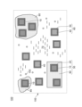
- FIG. 1 is a diagram showing a schematic structure of a light-responsive composition according to a first embodiment.
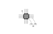
- FIG. 2 is a partial enlarged view showing a schematic configuration of a first particle according to the first embodiment.
- FIG. 2 is a partial enlarged view showing a schematic configuration of a first particle according to the first embodiment.
- FIG. 3 is a partial enlarged view showing a schematic configuration of a second particle according to the first embodiment.
- FIG. 3 is a partial enlarged view showing a schematic configuration of a second particle according to the first embodiment.
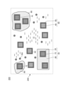
- FIG. 4 is a diagram showing a schematic structure of a light-responsive composition according to a second embodiment.
- FIG. 13 is a diagram showing a schematic structure of a light-responsive composition according to a third embodiment.
- FIG. 13 is a diagram showing a schematic structure of a wavelength conversion layer including a light-responsive composition according to a fourth embodiment.
- the photoresponsive composition 100 includes a medium 70.
- the photoresponsive composition 100 includes a first nanoparticle 10 having a photoresponsive perovskite-type crystal structure, a first protective layer 20 that protects the first nanoparticle 10, and a first particle 30 supported by the medium 70.
- the first protective layer 20 includes a first organic group 122 and a first bonding portion 110 that coordinates to the first nanoparticle 10, and is configured to protect the first nanoparticle 10.
- the first particle 30 is further configured to include a third protective layer 80 that is located between the medium 70 and the first protective layer 20 and protects the first particle.
- the photoresponsive composition 100 includes second nanoparticles 40 having a perovskite-type crystal structure with a different composition from the first nanoparticles 10, a second protective layer 50 that protects the second nanoparticles 40, and second particles 60 supported by a medium 70, as shown in FIG. 1.
- the second protective layer 50 is configured to have a second organic group 123 and a bonding portion 111 that coordinates to the second nanoparticles, as shown in FIGS. 2A to 2D.
- the first nanoparticles 10 and the second nanoparticles 40 are semiconductor nanocrystals having a perovskite crystal structure composed of an A site (monovalent cation), a B site (divalent cation), and an X site (monovalent anion including a halide anion).
- the perovskite crystal structure is alternatively referred to as a perovskite structure, an ABX3 crystal structure, or an ABX3 structure.
- the double perovskite crystal structure represented as A2B1B2X6 is also included in the perovskite crystal structure.
- At least one of the first nanoparticles 10 and the second nanoparticles 40 may be alternatively referred to as a luminescent nanoparticle, a luminescent nanocrystal, a photoresponsive nanocrystal, or a quantum dot.
- the average particle size of the nanoparticles is preferably 1 nm or more and 30 nm or less, and more preferably 2 nm or more and 25 nm or less. If the average particle size is less than 1 nm, the stability may be insufficient. If the average particle size is more than 30 nm, the dispersibility may be insufficient.
- a monovalent cation is adopted for the A site.
- the monovalent cation adopted for the A site include nitrogen-containing organic compound cations such as ammonium cation (NH 4 + ), alkylammonium cations having 6 or less carbon atoms, formamidinium cation (HC(NH 2 ) 2 + ), guanidinium cation (C(NH 2 ) 3 + ), imidazolium cation, pyridinium cation, and pyrrolidinium cation, and alkali metal cations such as lithium cation (Li + ), sodium cation (Na + ), potassium cation (K + ), rubidium cation (Rb + ), and cesium cation (Cs + ).
- nitrogen-containing organic compound cations such as ammonium cation (NH 4 + ), alkylammonium cations having 6 or less carbon atoms, formamidinium cation (HC(NH 2 ) 2 +
- These monovalent cations employed in the A site have small ionic diameters and are large enough to fit into the crystal lattice, allowing the perovskite compound to form stable three-dimensional crystals.
- alkylammonium cations having 6 or less carbon atoms include methylammonium cation (CH 3 NH 3 + ), ethylammonium cation (C 2 H 5 NH 3 + ), and propylammonium cation (C 3 H 7 NH 3 + ).
- At least one of methylammonium cation, formamidinium cation, and cesium cation is preferable to use at least one of methylammonium cation, formamidinium cation, and cesium cation as the A site, and from the viewpoint of suppressing color change, it is more preferable to use cesium cation as the A site.
- Two or more types of monovalent cations employed in these A sites may be used in combination.
- cesium salts can be used as raw materials in the synthesis of the first nanoparticle 10 and the second nanoparticle 40 of the luminescent nanocrystals described below.
- cesium salts cesium chloride, cesium bromide, cesium iodide, cesium hydroxide, cesium carbonate, cesium hydrogen carbonate, cesium bicarbonate, cesium formate, cesium acetate, cesium propionate, cesium pivalate, and cesium oxalate can be appropriately used.
- cesium salt candidates an appropriate one can be used depending on the synthesis method.
- a site is another alkali metal cation
- a salt in which the cesium element of the above cesium compound is replaced with another alkali metal cation element can be used as the raw material.
- a neutral compound other than a salt such as methylamine can be used as a raw material. Two or more of these raw materials may be used in combination.
- the B site of the perovskite crystal structure employs a divalent cation including a divalent transition metal cation or a divalent typical metal cation.
- divalent transition metal cation scandium cation (Sc 2+ ), titanium cation (Ti 2+ ), vanadium cation (V 2+ ), chromium cation (Cr 2+ ), manganese cation (Mn 2+ ), iron cation (Fe 2+ ), cobalt cation (Co 2+ ), nickel cation (Ni 2+ ), copper cation (Cu 2+ ), palladium cation (Pd 2+ ), europium cation (Eu 2+ ), and ytterbium cation (Yb 2+ ) are employed.
- divalent typical metal cations examples include magnesium cation (Mg 2+ ), calcium cation (Ca 2+ ), strontium cation (Sr 2+ ), barium cation (Ba 2+ ), zinc cation (Zn 2+ ), cadmium cation (Cd 2+ ), germanium cation (Ge 2+ ), tin cation (Sn 2+ ), and lead cation (Pb 2+ ).
- divalent typical metal cations are preferred in terms of growing stable three-dimensional crystals, tin cations or lead cations are more preferred, and lead cations are particularly preferred in terms of obtaining high luminescence intensity.
- Two or more of these divalent cations may be used in combination, and the perovskite crystal structure may be a so-called double perovskite type.
- the raw material for synthesizing the first nanoparticle 10 and the second nanoparticle 40 described below includes lead compounds, and an appropriate one can be used depending on the synthesis method.
- lead compounds that can be used include lead chloride, lead bromide, lead iodide, lead oxide, lead hydroxide, lead sulfide, lead carbonate, lead formate, lead acetate, lead 2-ethylhexanoate, lead oleate, lead stearate, lead naphthenate, lead citrate, lead maleate, and lead acetylacetonate.
- salts in which the lead element of the above-mentioned lead compounds is replaced with another divalent metal cation element can be used as the raw material. Two or more of these raw materials may be used in combination.
- a monovalent anion including a halide anion is adopted.
- the halide anion include fluoride anion (F - ), chloride anion (Cl - ), bromide anion (Br - ), and iodide anion (I - ).
- chloride anion, bromide anion, and iodide anion are preferred from the viewpoint of forming a stable three-dimensional crystal and exhibiting strong light emission in the visible light range.
- the light emission color is blue when chloride anion is used, green when bromide anion is used, and red when iodide anion is used.
- halide anions Two or more types may be used in combination.
- the emission wavelengths of the first nanoparticles 10 and the second nanoparticles 40 can be set to the desired wavelengths depending on the content ratio of the anion species.
- chloride anions, bromide anions, and iodide anions it is preferable because it is possible to obtain an emission spectrum that covers almost the entire range of visible light from blue to red while maintaining a narrow full width at half maximum depending on the content ratio of the anion species.
- the X site may contain a monovalent anion other than a halide anion.
- monovalent anions other than a halide anion include pseudohalide anions such as cyanide anion (CN-), thiocyanate anion (SCN-), and isothiocyanate anion (CNS-).
- CN- cyanide anion
- SCN- thiocyanate anion
- CNS- isothiocyanate anion
- appropriate ones can be selected according to the synthesis method from salts with counter cations at the A site and B site, such as cesium chloride and lead bromide, and salts with other cations.
- the first nanoparticles 10 and the second nanoparticles 40 in this embodiment can be manufactured by the following process.
- the hot injection method in which raw material liquids are mixed at high temperatures and then rapidly cooled after the generation of fine particles to obtain a stable product
- the ligand-assisted reprecipitation method in which fine particles are obtained by reprecipitation utilizing the difference in the miscibility of the product with the solvent, are used.
- a room temperature synthesis method is used in which a mixture of A-site raw materials and B-site raw materials, which are non-halogenated and do not contain X-site components, is mixed with a separately prepared X-site raw material liquid under mild conditions at around room temperature to obtain fine particles. Furthermore, this method is used in the mechanochemical method in which solid raw materials are reacted by mechanical mixing such as milling or ultrasonic treatment to obtain product fine particles, and in the in situ synthesis method in which crystals are grown directly after the raw material liquid is applied to a substrate to obtain the reactant.
- the first particles 30 described below contain a large amount of either bromine or iodine
- the second particles 60 contain a large amount of the other of either bromine or iodine.
- the first particles 30 in this embodiment include first nanoparticles 10 having a perovskite crystal structure, and a first protective layer 20 having a first organic group 122 and a first bonding portion 110 coordinated to the first nanoparticles 10 and protecting the first nanoparticles 10.
- the first particles 30 may be separated from each other, or a plurality of first particles 30 may be connected via the first protective layer 20 to form a secondary particle.
- the second particles 60 include second nanoparticles 40 having a perovskite crystal structure, and a second protective layer 50 having a second organic group 123 and a second bonding portion 111 coordinated to the second nanoparticles and protecting the second nanoparticles 40.
- the second particles 60 may be separated from each other, or a plurality of the second particles 60 may be connected to each other via the second protective layer 50 to form a secondary particle.
- the first particles 30 have a light-emitting characteristic of emitting more of either green or red
- the second particles 60 have a light-emitting characteristic of emitting more of the other of green or red.
- the first nanoparticle 10 is protected by a first protective layer 20 having organic groups 120, 122 and a bonding portion 110, and the second nanoparticle 40 is protected by a second protective layer 50 having organic groups 121, 123 and a bonding portion 111. It is presumed that the protective function is exhibited for the following two reasons. The first presumption is that the hydrophilic bonding portion is coordinated to the nanocrystal, completely or partially bonding with the halogen, which is also hydrophilic, making it difficult for the halogen to be detached from the nanocrystal.
- the protective layer may be composed of low molecular weight compounds or high molecular weight compounds. It may also contain both low molecular weight compounds and high molecular weight compounds. From the viewpoint of more effectively preventing color mixing, it is preferable for the protective layer to be composed mainly of high molecular weight compounds.
- polymer compound a copolymer (described below) obtained by polymerizing at least two types of monomers each containing the bonding portion and organic group listed below can be used.
- Examples of the first binding portion 110 and the second binding portion 111 include cationic groups, anionic groups, zwitterionic groups, and salts thereof.
- Examples of the anionic group include a carboxy group, a sulfo group, and a phosphoryl group.
- Examples of the cationic group include an amino group and a quaternary ammonium cation.
- Examples of the zwitterionic group include a carboxybetaine group, a phosphorylcholine group, and a sulfobetaine group.
- the first connecting portion 110 and the second connecting portion 111 may be the same connecting portion or different connecting portions.
- a linear, branched or cyclic alkyl group, a linear, branched or cyclic heteroalkyl group, an aryl group, a heteroaryl group, an aralkyl group or a heteroaralkyl group is adopted as the first organic group 120, 122 and the second organic group 121, 123. Any of the first organic group 120, 122 and the second organic group 121, 123 may have a substituent in a part of the organic group.
- the first organic groups 120 and 122 and the second organic groups 121 and 123 may be the same organic group or different organic groups.
- the content of the first protective layer 20 relative to the first nanoparticles 10 is preferably 1 part by mass to 1000 parts by mass, preferably 5 parts by mass to 500 parts by mass, more preferably 10 parts by mass to 300 parts by mass, with the content of the first nanoparticles 10 being 100 parts by mass. If it is less than 1 part by mass, the effect as a protective layer may not be fully exerted, and color mixing may not be prevented. If it is more than 1000 parts by mass, the solubility and dispersibility of the first protective layer 20 in the medium 70 may decrease, and color mixing may not be prevented.
- the content of the first protective layer 20 relative to the first nanoparticles 10 may be appropriately adjusted according to the type and application of the first nanoparticles 10 and the first protective layer 20.
- the content of the second protective layer 50 relative to the second nanoparticles 40 is preferably 1 part by mass to 1000 parts by mass, preferably 5 parts by mass to 500 parts by mass, and more preferably 10 parts by mass to 300 parts by mass, assuming that the content of the second nanoparticles 40 is 100 parts by mass. If it is less than 1 part by mass, the effect of the second protective layer 50 may not be fully exerted, and color mixing may not be prevented. If it is more than 1000 parts by mass, the solubility and dispersibility of the second protective layer 50 in the medium 70 may decrease, and color mixing may not be prevented.
- the content of the second protective layer 50 relative to the second nanoparticles 40 may be appropriately adjusted according to the type and application of the second nanoparticles 40 and the second protective layer 50.
- Methods for coordinating the first protective layer 20 on the surface of the first nanoparticle 10 include a method for applying the first protective layer 20 after the synthesis of the first nanoparticle 10, a method for allowing the first nanoparticle 10 and the first protective layer 20 to coexist during the synthesis of the first nanoparticle 10, etc.
- methods for coordinating the second protective layer 50 on the surface of the second nanoparticle 40 include a method for applying the second protective layer 50 after the synthesis of the second nanoparticle 40, a method for allowing the second nanoparticle 40 and the second protective layer 50 to coexist during the synthesis of the second nanoparticle 40, etc.
- Method for producing polymer compound A detailed description will be given below of a method for producing a polymer compound that can be used for the first protective layer 20 and the second protective layer 50.
- the method for producing the polymer compound is not particularly limited as long as it can produce the above-mentioned structure, but the polymer compound can be produced, for example, by the following method (i) or (ii).
- the method (i) for producing a polymer compound includes a method in which a monomer having a structural unit containing a bonding portion or an organic group is produced, and then the monomer is polymerized to produce the polymer compound. Furthermore, the method (ii) for producing a polymer compound includes a method in which a polymer main chain is synthesized, and then a bonding portion or an organic group is bonded to the polymer main chain.
- a vinyl ether derivative, an acrylate derivative, a methacrylate derivative, an ⁇ -olefin derivative, an aromatic vinyl derivative, etc. can be used as a monomer for introducing a bond into a polymer compound. From the viewpoint of ease of manufacturing the monomer, it is preferable to use an acrylate derivative or a methacrylate derivative as such a monomer.
- acrylate or methacrylate derivatives can be prepared by the methods described in the following documents. K. Ishihara and 2 others, "Polymer Journal” (Japan), The Society of Polymer Science, 1990, Vol. 22, p. 355-360
- the above monomers can be polymerized by radical polymerization or ionic polymerization. Living polymerization can also be used to control the molecular weight distribution or structure. From an industrial perspective, it is preferable to use radical polymerization.
- Radical polymerization can be carried out by using a radical polymerization initiator, by irradiating radiation or light such as laser light, by using a photopolymerization initiator in combination with light irradiation, by heating, etc.
- the radical polymerization initiator may be any that can generate radicals and initiate a polymerization reaction, and is selected from compounds that generate radicals by the action of heat, light, radiation, redox reactions, etc.
- azo compounds organic peroxides, inorganic peroxides, organometallic compounds, photopolymerization initiators, etc.
- examples of the initiator include azo compounds such as 2,2'-azobisisobutyronitrile (AIBN) and 2,2'-azobis(2,4-dimethylvaleronitrile); organic peroxides such as benzoyl peroxide (BPO), tert-butyl peroxypivalate, and tert-butylperoxyisopropyl carbonate; inorganic peroxides such as potassium persulfate and ammonium persulfate; and redox initiators such as hydrogen peroxide-iron(II) salt, BPO-dimethylaniline, and cerium(IV) salt-alcohol.
- Photopolymerization initiators include acetophenone, benzoin ether, and ketal types. Two or more of these radical polymerization initiators may be used in combination.
- the preferred polymerization temperature for the vinyl monomers varies depending on the type of polymerization initiator used, and is not particularly limited, but polymerization is generally carried out at temperatures between -30°C and 150°C, with a more preferred temperature range being between 40°C and 120°C.
- the amount of polymerization initiator used in this case is preferably 0.1 to 20 parts by mass per 100 parts by mass of the monomer, and the amount used is preferably adjusted so as to obtain a polymer compound with the desired molecular weight distribution.
- the polymerization method is not particularly limited and may be any method such as solution polymerization, suspension polymerization, emulsion polymerization, dispersion polymerization, precipitation polymerization, or bulk polymerization.
- the obtained polymer compound can be purified as necessary.
- purification method There are no particular limitations on the purification method, and methods such as reprecipitation, dialysis, and column chromatography can be used.
- the structure of the produced polymer compound can be identified using various instrumental analyses.
- Analytical instruments that can be used include nuclear magnetic resonance (NMR), gel permeation chromatography (GPC), and inductively coupled plasma atomic emission spectrometry (ICP-AES).
- the medium 70, 77 is selected from either a liquid (medium 70) or a solid (medium 77).
- a solvent or a polymerizable compound can be used. That is, the medium 70 can contain a polymerizable compound 150 or a solvent.
- a polymer matrix can be used.
- the medium 77 may contain a polymer matrix in which both the first particles 30 and the second particles 60 are dispersed.
- the polymer matrix can be a polymer obtained by crosslinking and polymerizing a polymerizable compound.
- the polymer matrix is in the form of a sheet having a sheet thickness that takes into consideration the purpose of ensuring the optical coupling surface of light reception and light emission, the deactivation depth (penetration depth) of the primary light, and the extraction efficiency of the secondary light.
- the solvent include alkanes such as pentane and hexane, cycloalkanes such as cyclopentane and cyclohexane, esters such as ethyl acetate, butyl acetate, and benzyl acetate, ethers such as diethyl ether and tetrahydrofuran, ketones such as cyclohexanone and acetone, and alcohols such as methanol, ethanol, isopropanol, butanol, and hexanol.
- monoacetate compounds such as diethylene glycol monoethyl ether acetate, ethylene glycol monoethyl ether acetate, diethylene glycol monobutyl ether acetate, and dipropylene glycol methyl ether acetate, diacetate compounds such as 1,4-butanediol diacetate and propylene glycol diacetate, and triacetate compounds such as glyceryl triacetate can also be used. Since the solvent is easily removed before the curing of the polymerizable compound, a solvent with a boiling point of 300° C. or less is adopted. The solvent may be referred to as a solvent in other words.
- Polymerizable compound Polymerization of the polymerizable compound 150 is accelerated by receiving energy such as light or heat, and the polymerizable compound 150 becomes a component that imparts viscosity to the photoresponsive composition and hardens it.
- the polymerizable compound may be a radically polymerizable compound or a cationic polymerizable compound. These may be used alone or in combination of two or more. In addition, either a photopolymerizable compound or a thermally polymerizable compound may be used.
- the form in which the polymerizable compound 150 is polymerized and the viscosity is increased may be referred to as a polymer 160.
- radically polymerizable compounds examples include monofunctional (meth)acrylate compounds, bifunctional (meth)acrylate compounds, trifunctional or higher (meth)acrylate compounds, hydroxyl group-containing (meth)acrylate compounds, carboxy group-containing (meth)acrylate compounds, and vinyl compounds.
- Examples of monofunctional (meth)acrylates include methyl (meth)acrylate, ethyl (meth)acrylate, propyl (meth)acrylate, isopropyl (meth)acrylate, butyl (meth)acrylate, hexyl (meth)acrylate, 2-ethylhexyl (meth)acrylate, cyclohexyl (meth)acrylate, dicyclopentenyl (meth)acrylate, dicyclopentenyloxyethyl (meth)acrylate, benzyl (meth)acrylate, and 3,3,5-trimethylcyclohexyl acrylate.
- tetrahydrofurfuryl (meth)acrylate phenoxyethyl (meth)acrylate, methoxyethyl (meth)acrylate, ethyl carbitol (meth)acrylate, isobornyl (meth)acrylate, methoxytriethylene glycol (meth)acrylate, (2-methyl-2-ethyl-1,3-dioxolan-4-yl)methyl (meth)acrylate, (3-ethyloxetan-3-yl)methyl (meth)acrylate, and cyclic trimethylolpropane formal (meth)acrylate can be used.
- bifunctional (meth)acrylate compounds include 1,4-butanediol di(meth)acrylate, 1,6-hexanediol di(meth)acrylate, 1,9-nonanediol di(meth)acrylate, ethylene glycol di(meth)acrylate, diethylene glycol di(meth)acrylate, triethylene glycol di(meth)acrylate, tetraethylene glycol di(meth)acrylate, polyethylene glycol 200 di(meth)acrylate, polyethylene glycol 300 di(meth)acrylate, polyethylene glycol 400 di(meth)acrylate, and polyethylene glycol 600.
- trifunctional or higher (meth)acrylate compounds examples include trimethylolpropane tri(meth)acrylate, trimethylolpropane EO-modified tri(meth)acrylate, trimethylolpropane PO-modified tri(meth)acrylate, glycerin propoxy tri(meth)acrylate, pentaerythritol tri(meth)acrylate, tris(acryloxyethyl)isocyanurate, and EO-modified pentaerythritol tetraacrylate.
- vinyl compounds examples include vinyl acetate, vinyl benzoate, vinyl pivalate, vinyl butyrate, vinyl methacrylate, and N-vinylpyrrolidone.
- cationic polymerizable compound either a photopolymerizable or thermally polymerizable compound can be used. These may be used alone or in combination of two or more types.
- Representative cationic polymerizable compounds include, for example, epoxy compounds, oxacene compounds, and vinyl ether compounds.
- the amount of the polymerizable compound, including the above radically polymerizable compound and cationic polymerizable compound, used is preferably 1 to 99 parts by mass, more preferably 3 to 90 parts by mass, and even more preferably 5 to 80 parts by mass, relative to the total parts by mass of the photoresponsive composition.
- the medium 70, 77 preferably has an organic group.
- the organic group at least one of a linear, branched, or cyclic alkyl group, a linear, branched, or cyclic heteroalkyl group, an aryl group, a heteroaryl group, an aralkyl group, or a heteroaralkyl group can be used.
- the substituents possessed by the medium 70, 77 may have a partially substituted substituent.
- the polymerization initiator is a compound that generates an active species that initiates a polymerization reaction by irradiation with active energy rays or heat, and a known polymerization initiator can be used.
- the main active species that initiate a polymerization reaction include a radical polymerization initiator that generates a radical and a cationic polymerization initiator that generates an acid, and these may be used in combination.
- acetophenones such as aminoketones, phosphines, and oxime ester compounds are preferred. These can be used alone or in combination depending on the properties desired for the cured product.
- the amount used is preferably 0.01 to 100 parts by mass, and more preferably 0.1 to 50 parts by mass, per 100 parts by mass of the total solid content in the composition.
- the third protective layer 80 is located between the medium 70, 77 and the first protective layer 20, and protects the first particles 30.
- the third protective layer 80 is located between the medium 70, 77 and the first protective layer 20, and in other words protects the first protective layer 20.
- the third protective layer 80 takes an embodiment containing a polymer compound having a third organic group in a side chain.
- the third protective layer 80 preferably has a lower absorbance (optical density) than the first nanoparticles in the first wavelength band including at least one of ultraviolet and blue and the second wavelength band related to the emission wavelength of the first nanoparticles.
- the third protective layer 80 containing the first particles 30 is preferably in the form of particles having a diameter of 10 nm to 10 ⁇ m.
- the third protective layer 80 preferably has a crosslinked structure.
- the third protective layer 80 is provided such that the first protective layer 20 is in contact with the third protective layer 80, and the second protective layer 50 is not in contact with the third protective layer 80.
- the third protective layer 80 is configured to encapsulate the first nanoparticles 10 but not the second nanoparticles 40.
- the third organic group at least one of a linear, branched or cyclic alkyl group, a linear, branched or cyclic heteroalkyl group, an aryl group, a heteroaryl group, an aralkyl group, or a heteroaralkyl group can be adopted.
- the third organic group may have a substituent group substituted on a part thereof.
- the method for forming the third protective layer 80 is not particularly limited, and examples thereof include a top-down method of microparticulating the bulk of the third protective layer 80 including the first particles 30, and a bottom-up method of microparticulating the bulk of the third protective layer 80 including the first particles 30. An appropriate method may be selected depending on the application.
- a bulk of the third protective layer 80 containing the first particles 30 is first formed.
- Methods for forming the bulk include polymerizing a mixture containing a polymerizable compound and the first particles 30, and mixing the first particles 30 with a polymer compound.
- Methods for microparticulating the bulk include dry grinding, wet grinding, freeze grinding, spray freeze drying, etc.
- Methods for microparticulating in a bottom-up manner include emulsion polymerization, suspension polymerization, dispersion polymerization, radical polymerization, emulsion polymerization, sol-gel, reprecipitation, microwave heating, etc.
- fine particles can be obtained by polymerizing styrene or methacrylic acid ester in an organic solvent using polydimethylsiloxane terminated with methacryloxypropyl groups as a stabilizer.
- the content of the third protective layer 80 relative to the first nanoparticles is preferably 1 part by mass to 1000 parts by mass, with the content of the first nanoparticles being 1 part by mass.
- the average surface distance of the first nanoparticles is 1 nm to 100 nm.
- the light-responsive composition may be used in combination with an oxygen remover, an antioxidant, a scattering agent such as titanium oxide, a surfactant, an anti-mold agent, a light stabilizer, or other additives that impart various properties, a diluting solvent, etc., as necessary.
- an oxygen remover an antioxidant
- a scattering agent such as titanium oxide, a surfactant, an anti-mold agent, a light stabilizer, or other additives that impart various properties, a diluting solvent, etc., as necessary.
- the light-responsive composition according to the second embodiment will be described with reference to Fig. 3.
- the light-responsive composition 200 according to the second embodiment differs from the light-responsive composition 100 according to the first embodiment in that the medium 77 contains a polymer 160 in which a polymerizable compound 150 is crosslinked to increase the viscosity.
- the light-responsive composition according to the third embodiment will be described with reference to Fig. 4.
- the light-responsive composition 300 according to the third embodiment differs from the light-responsive composition 100 according to the first embodiment and the light-responsive composition 200 according to the second embodiment in that the second particles 66 have a fourth protective layer 90.
- the fourth protective layer 90 is located between the medium 70, 77 and the second protective layer 50, and protects the second particles.
- the fourth protective layer 90 is located between the medium 70, 77 and the second protective layer 50, and protects the second protective layer 50.
- the fourth protective layer 90 preferably contains a polymer compound having a fourth organic group in a side chain.
- the fourth protective layer 90 preferably has a lower absorbance (optical density) than the second nanoparticles in the first wavelength band including at least one of ultraviolet and blue and the third band related to the emission wavelength of the second nanoparticles.
- the fourth protective layer 90 containing the second particles is preferably particulate with a diameter of 10 nm to 10 ⁇ m.
- the fourth protective layer 90 preferably has a crosslinked structure. Similarly to the third protective layer, the fourth protective layer 90 is provided such that the second protective layer 50 is in contact with the fourth protective layer 90 and the first protective layer 20 is not in contact with the fourth protective layer 90.
- the fourth protective layer 90 is configured to encapsulate the second nanoparticles 40 but not the first nanoparticles 10.
- the fourth organic group at least one of a linear, branched or cyclic alkyl group, a linear, branched or cyclic heteroalkyl group, an aryl group, a heteroaryl group, an aralkyl group, or a heteroaralkyl group can be adopted.
- the fourth organic group may have a substituent group substituted on a part thereof.
- the method for forming the fourth protective layer 90 is not particularly limited, and examples thereof include a top-down method of microparticulating the bulk of the fourth protective layer 90 containing the second particles, and a bottom-up method of microparticulating the bulk of the fourth protective layer 90 containing the second particles. An appropriate method may be selected depending on the application.
- a bulk of the fourth protective layer 90 containing the second particles is first formed.
- Methods for forming the bulk include polymerizing a mixture containing a polymerizable compound and the second particles, and mixing the second particles with a polymer compound.
- Methods for microparticulating the bulk include dry grinding, wet grinding, freeze grinding, and spray freeze drying.
- Methods for microparticulating in a bottom-up manner include emulsion polymerization, suspension polymerization, dispersion polymerization, radical polymerization, emulsion polymerization, sol-gel, reprecipitation, and microwave heating.
- fine particles can be obtained by polymerizing styrene or methacrylic acid ester in an organic solvent using polydimethylsiloxane terminated with methacryloxypropyl groups as a stabilizer.
- the content of the second nanoparticles in the fourth protective layer 90 is preferably 1 part by mass to 1000 parts by mass, with the content of the second nanoparticles being 1 part by mass.
- the average surface distance of the second nanoparticles is 1 nm to 100 nm.
- the light-responsive composition 100, 200, 300 having fluidity exhibits the effect of the present invention of reducing halogen exchange and stabilizing the composition even in the form of the light-responsive composition 100, 200, 300 cured on a substrate.
- the light-responsive composition 200 (100, 300) may be referred to as a wavelength conversion layer because it is in the form of a layer supported by another member.
- the support form includes a laminated form and a dispersed form dispersed in a matrix material.
- the wavelength conversion layer may be a film or sheet or a patterned pixel formed by applying the light-responsive composition onto a support member (substrate) and curing it.
- FIG. 5 shows the cross-sectional structure of a display element 400 according to the fourth embodiment.
- the display element 400 has a light-emitting layer 410, a dielectric multilayer film 417, and a wavelength conversion layer 420 stacked in a stacking direction D1.
- the downstream side in the stacking direction D1 corresponds to the side where a user who views the image drawn on the display element is located.
- the wavelength conversion layer 420 is separated from the wavelength conversion layer corresponding to the adjacent element by a black matrix BM that separates the pixels.
- the photoresponsive composition 200 is hardened together with the polymerizable compound 150 by carrying out a polymerization process such as photopolymerization.
- a polymerization process such as photopolymerization.
- the photoresponsive composition 200 is hardened, it becomes a solid photoresponsive composition 426 supported by the dielectric multilayer film 417.
- the photoresponsive composition 426 is configured to meet a predetermined dimension and constitutes the wavelength conversion layer 420 of the display element 400.
- the wavelength conversion layer 420 is a layer that is solidified by hardening the entire photoresponsive composition 200 together with the polymerizable compound 150.
- the light-emitting layer 410 corresponds to a light source that emits light L1 of a first wavelength ⁇ 1.
- the wavelength conversion layer 420 has an optical coupling surface 422 that is optically coupled to the light-emitting layer 410 on the side of the light-emitting layer 410, and an extraction surface 424 on the opposite side of the light-emitting layer 410 that is converted by the wavelength conversion layer 420 and extracts the secondary light L2.
- the wavelength conversion layer 420 of this embodiment receives primary light L1 of wavelength ⁇ 1 propagating through the dielectric multilayer film 417.
- the dielectric multilayer film 417 provides the display element 400 with the spectral transmission characteristics of the primary light from the light emitting layer 410 and the spectral reflection characteristics of secondary light L2 of wavelength ⁇ 2 emitted in the wavelength conversion layer 420.
- the wavelength ⁇ 2 of the secondary light L2 is longer than the wavelength ⁇ 1 of the primary light L1.
- the dielectric multilayer film 417 can be replaced with another optical member that is optically transparent to the first wavelength ⁇ 1 emitted by the light-emitting layer 410.
- another optical member (not shown) can be disposed in front of the extraction surface 424 (opposite the light-emitting layer 410).
- the method for forming the wavelength conversion layer is not particularly limited, and examples thereof include a method in which a photoresponsive composition is applied onto a substrate, and then pre-dried as necessary, and further, if necessary, heated or irradiated with active energy rays to cure the film.
- the thickness of the cured wavelength conversion layer is preferably 0.1 to 200 ⁇ m, more preferably 1 to 100 ⁇ m.
- the active energy rays in the active energy ray irradiation are appropriately selected from electromagnetic waves such as heat rays, ultraviolet rays, visible light, near infrared rays, and electron beams that reduce fluidity and promote curing through polymerization, crosslinking, drying, etc.
- Light sources that have a dominant wavelength of emission in the wavelength range of 100 to 450 nm are preferred as light sources for applying active energy rays.
- Examples of such light sources include ultra-high pressure mercury lamps, high pressure mercury lamps, medium pressure mercury lamps, mercury xenon lamps, metal halide lamps, high power metal halide lamps, xenon lamps, pulsed xenon lamps, deuterium lamps, fluorescent lamps, ND-YAG triple harmonic lasers, HE-CD lasers, nitrogen lasers, XE-Cl excimer lasers, XE-F excimer lasers, semiconductor pumped solid state lasers, and LED lamp light sources with emission wavelengths of 365 nm, 375 nm, 385 nm, 395 nm, and 405 nm.
- the molecular weight distribution of the polymer compound in the first and second protective layers can be calculated in terms of monodisperse polymethyl methacrylate by gel permeation chromatography (GPC).
- GPC gel permeation chromatography
- the molecular weight can be measured by GPC, for example, as follows: This can be done as shown.
- the sample is added to the eluent described below so that the sample concentration becomes 1% by mass, and the solution is allowed to stand at room temperature for 24 hours to dissolve.
- the solution is filtered through a solvent-resistant membrane filter having a pore size of 0.45 ⁇ m to obtain a sample solution, which is then measured under the following conditions.
- Apparatus Agilent 1260 infinity system (Agilent Technologies) Column: PFG analytical linear M columns (PSS) Eluent: 2,2,2-trifluoroethanol Flow rate: 0.2 ml/min Oven temperature: 40°C Sample injection volume: 20 ⁇ L
- composition of the first and second protective layers can be analyzed by nuclear magnetic resonance (NMR).
- NMR nuclear magnetic resonance
- 1H-NMR and 13C-NMR spectrum measurements are performed using an ECA-600 (600 MHz) manufactured by JEOL Ltd. The measurements are performed at 25°C in a deuterated solvent containing tetramethylsilane as an internal standard.
- the chemical shift value is read as a ppm shift value ( ⁇ value) with the internal standard tetramethylsilane set to 0.
- Crystal structure analysis The crystal structure analysis and composition analysis of the first nanoparticles and the second nanoparticles can be performed using X-ray diffraction (XRD).
- XRD X-ray diffraction
- RINT 2100 manufactured by Rigaku Corporation
- ED electron diffraction
- compositional analysis of the first nanoparticles and the second nanoparticles can also be performed using XPS and ICP emission spectroscopy.
- the molar ratio of A and B can be measured from the signal intensity of XPS, and the concentration of X can be measured from the emission intensity of ICP emission spectroscopy (e.g., CIROS CCD (manufactured by SPECTRO)).
- the amount of the first nanoparticles 10 or the second nanoparticles 40 contained in the light-responsive composition 100 can be measured using ICP emission spectroscopy.
- the amount of Pb can be measured from the emission intensity of ICP emission spectroscopy, and compared with the composition information of the first nanoparticles 10 and the second nanoparticles 40 obtained by the above method, thereby calculating the amount of the first nanoparticles 10 and the second nanoparticles 40.
- the amounts of the first and second protective layers on the first and second nanoparticles can be determined by TG-DTA measurement. They can also be determined from the integrated intensity of NMR of the first particle 30 or the second particle 40.
- composition analysis can be performed using NMR and mass spectrometry, and when the medium 77 is in a solid (cured) form, composition analysis can be performed using pyrolysis gas chromatography.
- the amount of the first nanoparticles 10 contained in the first particles 30 can be measured using ICP emission spectrometry.
- a mixture containing the third protective layer 80, the first nanoparticles 10, and the first protective layer 20 may be decomposed with an acid and analyzed by ICP emission spectrometry.
- the amount of the second particles 40 contained in the second particles 60 may be determined in the same manner.
- the particle size of the first particle 30 including the third protective layer 80 can be calculated by TEM observation.
- the average inter-surface distance of the first nanoparticles 10 contained in the first particle 30 can be calculated by TEM observation.
- the resulting reaction mixture was heated at 70°C for 8 hours under a nitrogen atmosphere to complete the polymerization reaction. After cooling the reaction solution to room temperature, 300 parts of water was added to precipitate the product. After centrifugation, the supernatant was removed. The solvent was removed by distillation under reduced pressure, and the polymer compound a was obtained by drying under reduced pressure at 50°C and 0.1 kPa or less. NMR measurement confirmed that the ratio of units containing sulfobetaine groups in the polymer was 18 mol%.
- Polymer compound b was produced in the same manner as polymer compound a, except that the amount of 3-[[2-(methacryloyloxy)ethyl]dimethylammonio]propane-1-sulfonic acid was changed from 26.5 parts to 10.2 parts, and the amount of hexyl methacrylate was changed from 42.3 parts to 45.4 parts in the production of polymer compound a. It was confirmed by NMR measurement that the ratio of units containing sulfobetaine groups in the polymer was 12 mol%.
- Polymer compound c was produced in the same manner as polymer compound a, except that 25.4 parts of 3-[[2-(methacryloyloxy)ethyl]dimethylammonio]propane-1-sulfonic acid was replaced with 4.7 parts of methacrylic acid and 42.3 parts of hexyl methacrylate, instead of 45.4 parts. NMR measurement confirmed that the ratio of units containing a carboxyl group in the polymer was 18 mol%.
- Toluene solution of polymer compound b A toluene solution of polymer compound b was prepared in the same manner as the toluene solution of polymer compound a, except that polymer compound b was used instead of polymer compound a.
- Toluene solution of polymer compound c A toluene solution of polymer compound c was prepared in the same manner as the toluene solution of polymer compound a, except that polymer compound c was used instead of polymer compound a.
- a second nanoparticle dispersion b having a perovskite crystal structure of CsPb(Br/I) 3 was obtained in the same manner as in the luminescent nanocrystal dispersion a, except that 3.2 parts of lead(II) bromide and 9.3 parts of lead(II) iodide were used instead of 10 parts of lead(II) bromide.
- Example 1 [Preparation of first particles 30-1] 10 parts of the first nanoparticle dispersion a was placed in a container, and the solvent was distilled off under reduced pressure. 10 parts of a toluene solution of polymer compound a was added thereto, and the mixture was stirred for 1 hour, and the solvent was distilled off under reduced pressure. 10 parts of hexane was added to obtain a hexane dispersion of first particles 30-1.
- particle 1 including third protective layer 80 and first particle 30 parts of the hexane dispersion of the first particles 30-1, 200 parts of hexane, 5 parts of polydimethylsiloxane terminated with methacryloxypropyl groups (manufactured by Gelest, product name DMS-R22), 30 parts of methyl methacrylate, 3 parts of trimethylolpropane trimethacrylate, and 2 parts of 2,2′-azobis(4-methoxy-2,4-dimethylvaleronitrile) were mixed and reacted at 40° C. for 2 hours.
- methacryloxypropyl groups manufactured by Gelest, product name DMS-R22
- first particles 30-1 including a third protective layer 80, first nanoparticles 10, and a first protective layer 20.
- a second particle 60-1 including a fourth protective layer 90, a second particle 40, and a second protective layer 50 was obtained in the same manner as the first particle 30-1 including a third protective layer 80, a first nanoparticle 10, and a first protective layer 20, except that a second particle 60-1 was used instead of the first particle 30-1.
- a photoresponsive composition 1 was obtained by mixing 10 parts of the first particle 30-1 including the third protective layer 80, the first nanoparticle 10, and the first protective layer 20, 10 parts of the particle 1 including the fourth protective layer 90, the second particle 40, and the second protective layer 50, 75 parts of butyl acrylate, and 5 parts of 2,4,6-trimethylbenzoyl-diphenyl-phosphine oxide (manufactured by IGM Resins, product name OmniradTPO).
- Example 2 [Preparation of first particles 30-2] A hexane dispersion of the first particles 30-2 was obtained in the same manner as the hexane dispersion of the first particles 30-1, except that the polymer compound a was changed to the polymer compound c.
- first particle 30-2 including third protective layer 80, first nanoparticle 10, and first protective layer 20 A first particle 30-2 including a third protective layer 80, a first nanoparticle 10, and a first protective layer 20 was obtained in the same manner as the first particle 30-1 including a third protective layer 80, a first nanoparticle 10, and a first protective layer 20, except that the first particle 30-2 was used instead of the first particle 30-1.
- a second particle 60-2 including a fourth protective layer 90, a second nanoparticle 40, and a second protective layer 50 was obtained in the same manner as the first particle 30-1 including a fourth protective layer 90, a second nanoparticle 40, and a second protective layer 50, except that the first particle 30-2 was used instead of the first particle 30-1.
- a light-responsive composition 2 was obtained in the same manner as the light-responsive composition 1, except that the first particles 30-2 were used instead of the first particles 30-1, and the second particles 60-2 were used instead of the second particles 60-1.
- Example 3 [Preparation of Photoresponsive Composition 3] 10 parts of the hexane dispersion of the second particles 60-1 were placed in a container and the solvent was distilled off under reduced pressure. Thereto, 10 parts of the first particles 30-1 including the third protective layer 80 and the first nanoparticles 10, 75 parts of butyl acrylate, and 5 parts of 2,4,6-trimethylbenzoyl-diphenyl-phosphine oxide (manufactured by IGM Resins, product name OmniradTPO) were mixed to obtain a photoresponsive composition 3.
- IGM Resins product name OmniradTPO
- composition of each photoresponsive composition is shown in Table 1.
- Measurement equipment Absolute PL quantum yield measurement equipment C9920-03 (manufactured by Hamamatsu Photonics)
- Excitation light wavelength 460 nm
- Excitation light integration range Excitation light wavelength ⁇ 10 nm
- Emission integral range (excitation light wavelength + 20) nm to 770 nm
- ⁇ Evaluation criteria> The absolute value of the difference in wavelength at which the emission was maximum in the range of 500 nm to 600 nm was calculated immediately after preparation and 5 minutes later, and evaluation was performed according to the following criteria.
- photoresponsive compositions 1 to 3 according to Examples 1 to 3 have reduced color mixing compared to photoresponsive composition 4 according to Comparative Example 1. This is presumably because the two types of nanoparticles with perovskite structures are protected by multiple protective layers with specific structures.
- the photoresponsive composition according to each embodiment described in this specification corresponds to at least one of the following configurations 1 to 18.
- Configuration 1 The media, a first nanoparticle having a photoresponsive perovskite-type crystal structure; a first protective layer having a first organic group and a first bonding portion coordinated to the first nanoparticle, and protecting the first nanoparticle; and a third protective layer located between the medium and the first protective layer, and protecting the first particle; and a first particle supported by the medium; a second nanoparticle having a perovskite-type crystal structure with a different composition from that of the first nanoparticle; and a second protective layer having a second organic group and a binding portion coordinated to the second nanoparticle and protecting the second nanoparticle, the second particle being supported by the medium;
- a light-responsive composition comprising:
- Configuration 2 The photoresponsive composition according to configuration 1, wherein the third protective layer contains a polymer having a third organic group in a side chain.
- Configuration 3 The light-responsive composition according to configuration 1 or 2, wherein the first protective layer is in contact with the third protective layer, and the second protective layer is not in contact with the third protective layer.
- Configuration 4 The light-responsive composition according to configuration 1 or 2, wherein the first protective layer is protected by the third protective layer.
- Configuration 5 The light-responsive composition according to any one of configurations 1 to 4, wherein the third protective layer encapsulates the first particles but does not encapsulate the second particles.
- Configuration 6 The photoresponsive composition according to any one of configurations 1 to 5, wherein the third protective layer has lower absorbance than the first nanoparticles in a first wavelength band including at least one of ultraviolet and blue and in a second wavelength band related to an emission wavelength of the first nanoparticles.
- Configuration 7 The photoresponsive composition according to any one of configurations 1 to 6, wherein the medium comprises a polymerizable compound.
- Configuration 8 8. The light-responsive composition according to claim 7, wherein the medium comprises a solvent.
- Configuration 9 The photoresponsive composition according to any of configurations 1 to 8, wherein said medium comprises a polymer matrix in which said first particles and said second particles are each dispersed.
- Configuration 10 10. The light-responsive composition according to claim 9, wherein the medium is a sheet-like solid.
- Configuration 11 The light-responsive composition according to embodiment 1, wherein the second particles are located between the medium and the second protective layer, and further comprises a fourth protective layer that protects the second particles.
- Configuration 12 12. The photoresponsive composition according to claim 11, wherein the fourth protective layer contains a polymer having a fourth organic group in a side chain.
- Configuration 13 The light-responsive composition according to embodiment 11 or 12, wherein the second protective layer is in contact with the fourth protective layer, and the first protective layer is not in contact with the fourth protective layer.
- Configuration 14 The light-responsive composition according to any one of configurations 11 to 13, wherein the second protective layer is protected by the fourth protective layer.
- Configuration 15 The light-responsive composition according to any one of claims 11 to 14, wherein the fourth protective layer encapsulates the second particles but does not encapsulate the first particles.
- Configuration 16 The photoresponsive composition according to any one of configurations 11 to 15, wherein the fourth protective layer has lower absorbance than the first nanoparticles in a first wavelength band including at least one of ultraviolet and blue and in a third wavelength band related to the emission wavelength of the second nanoparticles.
- Configuration 17 The photoresponsive composition according to any one of structures 1 to 16, wherein the first particles exhibit a light-emitting characteristic of emitting more of either green or red, and the second particles exhibit a light-emitting characteristic of emitting more of the other of green or red.
- Configuration 18 18. The photoresponsive composition according to any one of configurations 1 to 17, wherein the first particles contain either bromine or iodine in a large amount, and the second particles contain either the other of bromine or iodine in a large amount.
Landscapes
- Chemical & Material Sciences (AREA)
- Organic Chemistry (AREA)
- Engineering & Computer Science (AREA)
- Materials Engineering (AREA)
- Inorganic Chemistry (AREA)
- Physics & Mathematics (AREA)
- General Physics & Mathematics (AREA)
- Optics & Photonics (AREA)
- Chemical Kinetics & Catalysis (AREA)
- Medicinal Chemistry (AREA)
- Polymers & Plastics (AREA)
- Health & Medical Sciences (AREA)
- Luminescent Compositions (AREA)
- Optical Filters (AREA)
Abstract
Description
図1、図2A~図2Dを用いて、第1の実施形態に係る光応答性組成物について説明する。
本実施形態における第1のナノ粒子10、第2のナノ粒子40は、Aサイト(1価のカチオン)、Bサイト(2価のカチオン)及び、Xサイト(ハロゲン化物アニオンを含む1価のアニオン)を構成成分とするペロブスカイト型結晶構造を有する半導体のナノ結晶が採用される。ペロブスカイト型結晶構造は、ペロブスカイト型構造、ABX3型結晶構造、ABX3型構造と換言される。また、A2B1B2X6と表されるダブルペロブスカイト型結晶構造もペロブスカイト型結晶構造に含まれる。本願明細書において、第1のナノ粒子10、第2のナノ粒子40の少なくともいずれか一方を、発光性ナノ粒子、発光性ナノ結晶、光応答性ナノ結晶、量子ドットをと換言する場合がある。
Aサイトは、1価のカチオンが採用される。Aサイトに採用される1価のカチオンは、アンモニウムカチオン(NH4 +)、及び炭素数6以下のアルキルアンモニウムカチオン、ホルムアミジニウムカチオン(HC(NH2)2 +)、グアニジニウムカチオン(C(NH2)3 +)、イミダゾリウムカチオン、ピリジニウムカチオン、ピロリジニウムカチオン等の含窒素有機化合物カチオンが挙げられ、リチウムカチオン(Li+)、ナトリウムカチオン(Na+)、カリウムカチオン(K+)、ルビジウムカチオン(Rb+)、及びセシウムカチオン(Cs+)等のアルカリ金属カチオンが挙げられる。
ペロブスカイト型結晶構造のBサイトは、2価の遷移金属カチオンまたは2価の典型金属カチオンを含む2価のカチオンが採用される。
ペロブスカイト型結晶構造のXは、ハロゲン化物アニオンを含む1価のアニオンが採用される。ハロゲン化物アニオンとしては、フッ化物アニオン(F-)、塩化物アニオン(Cl-)、臭化物アニオン(Br-)、ヨウ化物アニオン(I-)等が挙げられる。中でも、塩化物アニオン、臭化物アニオン又はヨウ化物アニオンが、安定な3次元結晶を形成し、可視光域に強い発光を示す観点から好ましい。発光色は、塩化物アニオンを用いると青、臭化物アニオンを用いると緑、ヨウ化物アニオンを用いると赤となる。
本実施形態において第1の粒子30は、図1に示すように、ペロブスカイト型結晶構造を有する第1のナノ粒子10と、第1の有機基122と第1のナノ粒子10に配位する第1の結合部110とを有し第1のナノ粒子10を保護する第1の保護層20と、を含む。第1の粒子30は、1粒1粒が離間していても、第1の保護層20を介して、複数の第1の粒子30が繋がって二次粒子を構成していてもよい。
第2の粒子60は、ペロブスカイト型結晶構造を有する第2のナノ粒子40と、第2の有機基123と第2のナノ粒子に配位する第2の結合部111とを有し第2のナノ粒子40を保護する第2の保護層50と、を含む。第2の粒子60は、1粒1粒が離間していても、第2の保護層50を介して、複数の第2の粒子60が繋がって二次粒子を構成していてもよい。
第1のナノ粒子10は、有機基120、122と結合部110を有する第1の保護層20によって、第2のナノ粒子40は、有機基121、123と結合部111を有する第2の保護層50によってそれぞれ保護されている。保護機能が発現するのは、以下の2つの理由によると推定される。1つ目の推定は、親水性を有する結合部がナノ結晶に配位することで、同じく親水性であるハロゲンと、完全にあるいは部分的に結合を作り、ハロゲンがナノ結晶から脱離しにくくなることが推定された。
第1の結合部110、第2の結合部111としては、カチオン性基、アニオン性基、双性イオン性基、それらの塩が挙げられる。アニオン性基としては、例えば、カルボキシ基、スルホ基、ホスホリル基、カチオン性基としては、例えば、アミノ基、4級アンモニウムカチオン、双性イオン性基としては、例えばカルボキシベタイン基、ホスホリルコリン基、スルホベタイン基などが挙げられる。
第1の有機基120、122、第2の有機基121、123は、直鎖状、分岐状若しくは環状のアルキル基、直鎖状、分岐状若しくは環状のヘテロアルキル基、アリール基、ヘテロアリール基、アラルキル基、又は、ヘテロアラルキル基、が採用される。第1の有機基120、122、第2の有機基121、123のいずれも、その有機基の一部に置換基を有していても良い。
第1の保護層20の第1のナノ粒子10に対する含有量は、好ましくは第1のナノ粒子10の含有量を100質量部として、1質量部~1000質量部、好ましくは5質量部~500質量部、より好ましくは10質量部~300質量部である。1質量部未満の場合、保護層としての効果が十分に発揮されず、混色を防止できない場合がある。1000質量部より多い場合、第1の保護層20の媒体70に対する溶解性、分散性が低下し、混色を防止できない場合がある。第1の保護層20の第1のナノ粒子10に占める含有量は、第1のナノ粒子10、第1の保護層20の種類や用途に合わせて適宜調整すればよい。
以下に、第1の保護層20、第2の保護層50に用いることのできる高分子化合物の製造方法について詳細に説明する。高分子化合物の製造方法は、上記の構造のものが得られれば特に限定されるものではないが、例えば以下のような方法(i)または(ii)で製造することができる。
K.Ishihara、他2名、「Polymer Journal」、(日本)、高分子学会、1990年、第22巻、p.355-360
媒体70、77は、図1、図3に示す通り、液体(媒体70)、固体(媒体77)のいずれかから選択される。液体としては、溶媒、重合性化合物を用いることができる。すなわち、媒体70は、重合性化合物150、あるいは、溶媒、を含むことができる。固体としては、ポリマーマトリクスを用いることができる。媒体77は、第1の粒子30,第2の粒子60のいずれをも分散するポリマーマトリクスを含む場合がある。ポリマーマトリクスは重合性化合物を架橋して重合化した重合体を採用することが可能である。ポリマーマトリクスは、受光、発光の光学的な結合面を担保する目的、一次光の失活深さ(侵入深さ)、二次光の取り出し効率、が考慮されたシート厚のシート形態が採用される。溶媒としては、例えば、ペンタン、ヘキサンなどのアルカン類、シクロペンタン、シクロヘキサンなどのシクロアルカン類、酢酸エチル、酢酸ブチル、酢酸ベンジルなどのエステル類、ジエチルエーテル、テトラヒドロフランなどのエーテル類、シクロヘキサノン、アセトンなどのケトン類、メタノール、エタノール、イソプロパノール、ブタノール、ヘキサノールなどのアルコール類を用いることができる。また、ジエチレングリコールモノエチルエーテルアセテート、エチレングリコールモノエチルエーテルアセテート、ジエチレングリコールモノブチルエーテルアセテート、ジプロピレングリコールメチルエーテルアセテート等のモノアセテート化合物、1,4-ブタンジオールジアセテート、プロピレングリコールジアセテート等のジアセテート化合物、グリセリルトリアセテート等のトリアセテート化合物も用いることができる。重合性化合物の硬化前に溶媒を除去しやすいことから、溶媒の沸点は300℃以下が採用される。溶媒は、溶剤と換言される場合がある。
重合性化合物150は、光、熱等のエネルギーを受けて重合が促進され、光応答性組成物に粘性を付与し硬化させる成分となる。重合性化合物は、ラジカル重合性化合物又はカチオン重合性化合物を使用することができる。これらは、1種類を単独で使用しても、2種類以上を組み合わせて使用してもよい。また、光重合性化合物又は熱重合性化合物のいずれも使用することができる。本願明細書において、重合性化合物150を重合し粘度を増大した形態を重合体160と換言する場合がある。
重合反応では、一般的に重合開始剤と重合性化合物とを併用する。重合開始剤としては、活性エネルギー線照射や熱により、重合反応を開始する活性種を発生させる化合物であり、公知の重合開始剤を用いることが可能である。重合反応を開始させる主な活性種としては、ラジカルを発生させるラジカル重合開始剤と酸を発生させるカチオン重合開始剤とが挙げられ、これらを併用してもよい。活性エネルギー線によりラジカルを発生させる光ラジカル重合開始剤としては、例えば、ジエトキシアセトフェノン、2-ヒドロキシ-2-メチル-1-フェニルプロパン-1-オン、ベンジルメチルケタール、4-(2-ヒドロキシエトキシ)フェニル-(2-ヒドロキシ-2-プロピル)ケトン、1-ヒドロキシシクロヘキシルフェニルケトン、2-メチル-1-[4-(メチルチオ)フェニル]-2-モルホリノプロパン-1-オン、2-ベンジル-2-ジメチルアミノ-1-(4-モルホリノフェニル)ブタン、オリゴ[2-ヒドロキシ-2-メチル-1-[4-(1-メチルビニル)フェニル]プロパノン]、2-ヒドロキシ-1-[4-[4-(2-ヒドロキシ-2-メチルプロピオニル)ベンジル]フェニル]-2-メチルプロパン-1-オン等のアセトフェノン類;ベンゾイン、ベンゾインメチルエーテル、ベンゾインエチルエーテル、ベンゾインイソプロピルエーテル、ベンゾインイソブチルエーテル等のベンゾイン類;2,4,6-トリメチルベンゾイル-ジフェニル-ホスフィンオキサイド、ビス(2,4,6-トリメチルベンゾイル)-フェニルホスフィンオキサイド等のホスフィン類;その他フェニルグリオキシリックメチルエステルが挙げられる。
第3の保護層80は、媒体70、77と第1の保護層20との間に位置し、第1の粒子30を保護する。第3の保護層80は、媒体70、77と第1の保護層20との間に位置し、第1の保護層20を保護すると換言される。第3の保護層80は、第3の有機基を側鎖に有する高分子化合物を含有する態様をとる。また、第3の保護層80は、紫外および青色の少なくともいずれかを含む第1の波長帯域と第1のナノ粒子の発光波長に係る第2の波長帯域と、において、それぞれ、第1のナノ粒子より低い吸光度(光学密度)を有することが好ましい。第1の粒子30を含有する第3の保護層80は、直径10nm~10μmの粒子状であることが好ましい。第3の保護層80は、架橋構造を有することが好ましい。また、第3の保護層80は、第1の保護層20が第3の保護層80に接し、第2の保護層50は第3の保護層80に接しないように設けられる。また、第3の保護層80は、第1のナノ粒子10を内包する一方で、第2のナノ粒子40を内包しないように構成される。このように第3の保護層80を設けることで、第1のナノ粒子10、第2のナノ粒子40のそれぞれに由来するハロゲンの媒体70、77を介した交換がより一層制限される。
第3の有機基としては、直鎖状、分岐状若しくは環状のアルキル基、直鎖状、分岐状若しくは環状のヘテロアルキル基、アリール基、ヘテロアリール基、アラルキル基、又は、ヘテロアラルキル基の少なくともいずれかを採用することができる。第3の有機基は、その一部が置換された置換基を有していても良い。
第3の保護層80を形成する手法としては、特に制限されず、第1の粒子30を含む第3の保護層80のバルク体を、トップダウン的に微粒子化する手法、ボトムアップ的に微粒子化する手法が挙げられる。用途に応じて、適宜手法を選択すればよい。
本実施形態において、光応答性組成物は、必要に応じて、酸素除去剤、酸化防止剤、酸化チタン等の散乱剤、界面活性剤、防カビ剤、光安定化剤やその他種々の特性を付与する添加剤、希釈溶剤等と混合して使用してもよい。
図3を用いて、第2の実施形態に係る光応答性組成物について説明する。第2の実施形態に係る光応答性組成物200は、重合性化合物150が架橋され粘度を増加させた重合体160を媒体77が含有する点において、第1の実施形態に係る光応答性組成物100と相違する。
図4を用いて、第3の実施形態に係る光応答性組成物について説明する。第3の実施形態に係る光応答性組成物300は、第2の粒子66が第4の保護層90を有する点において、第1の実施形態に係る光応答性組成物100、第2の実施形態に係る200と相違する。
第4の保護層90は、媒体70、77と第2の保護層50との間に位置し、第2の粒子を保護する。第4の保護層90は、媒体70、77と第2の保護層50との間に位置し、第2の保護層50を保護すると換言される。第4の保護層90は、第4の有機基を側鎖に有する高分子化合物を含有することが好ましい。また、第4の保護層90は、紫外および青色の少なくともいずれかを含む第1の波長帯域と第2のナノ粒子の発光波長に係る第3の帯域と、において、それぞれ、第2のナノ粒子より低い吸光度(光学密度)を有することが好ましい。第2の粒子を含有する第4の保護層90は、直径10nm~10μmの粒子状であることが好ましい。第4の保護層90は、架橋構造を有することが好ましい。また、第4の保護層90は、第3の保護層と同様にして、第2の保護層50が第4の保護層90に接し、第1の保護層20は第4の保護層90に接しないように設けられる。また、第4の保護層90は、第2のナノ粒子40を内包する一方で、第1のナノ粒子10を内包しないように構成される。このように第4の保護層90を設けることで、第1のナノ粒子10、第2のナノ粒子40のそれぞれに由来するハロゲンの媒体70、77を介した交換がより一層制限される。
第4の有機基としては、直鎖状、分岐状若しくは環状のアルキル基、直鎖状、分岐状若しくは環状のヘテロアルキル基、アリール基、ヘテロアリール基、アラルキル基、又は、ヘテロアラルキル基の少なくともいずれかを採用することができる。第4の有機基は、その一部が置換された置換基を有していても良い。
第4の保護層90を形成する手法としては、特に制限されず、第2の粒子を含む第4の保護層90のバルク体を、トップダウン的に微粒子化する手法、ボトムアップ的に微粒子化する手法が挙げられる。用途に応じて、適宜手法を選択すればよい。
流動性を有する光応答性組成物100、200、300は、基材上で、光応答性組成物100、200、300を硬化させた形態においても、ハロゲン交換を低減し組成を安定化する本発明の効果が発現する。光応答性組成物200(100、300)は、他の部材に支持された層形態をとるため波長変換層と換言される場合がある。支持形態には、積層形態、マトリクス材料に分散された分散形態が含まれる。波長変換層は、光応答性組成物を、支持部材(基材)上に塗工し硬化させて、フィルム又はシートまたはパターニングされた画素としたものが挙げられる。
波長変換層の形成方法は、特に制限されず、例えば、基材上に光応答性組成物を塗工した後、必要に応じてプレ乾燥を行い、さらに必要に応じて、加熱処理や活性エネルギー線照射を行うことで、膜を硬化させる方法が挙げられる。硬化後の波長変換層の厚みは、好ましくは0.1~200μm、より好ましくは1~100μmである。
各種物性測定は、以下のようにして行うことができる。
第1、2の保護層中の高分子化合物の分子量分布は、ゲル浸透クロマトグラフィー(GPC)によって、単分散ポリメタクリル酸メチル換算で算出することができる。GPCによる分子量の測定は、例えば以下に示すように行うことができる。
装置:Agilent 1260 infinity system(アジレント・テクノロジーズ社製)
カラム:PFG analytical linear M columns(PSS社製)
溶離液:2,2,2-トリフルオロエタノール
流速:0.2ml/min
オーブン温度:40℃
試料注入量:20μL
第1、2の保護層の組成分析は、核磁気共鳴(NMR)を用いて行うことができる。例えば、日本電子(株)製ECA-600(600MHz)を用い、1H-NMR、及び、13C-NMRのスペクトル測定を行う。その際、内部標準物質としてテトラメチルシランを含む重水素化溶剤中、25℃で測定を行う。化学シフト値は内部標準物質であるテトラメチルシランを0としたppmシフト値(δ値)を読み取る。
第1のナノ粒子、第2のナノ粒子の結晶構造解析、及び組成分析は、X線回折(XRD)を用いて行うことができる。例えば、RINT 2100(リガク製)を用いてX線回折パターンを測定することにより、結晶構造、及び組成を解析できる。分析検体の形態、サイズによっては、断面TEMに付帯する電子線回折(ED)が採用される場合がある。
第1のナノ粒子、第2のナノ粒子のそれぞれの組成分析は、XPSとICP発光分光分析を用いて行うこともできる。XPSの信号強度からA及びBのモル比を、ICP発光分光分析(例えば、CIROS CCD(SPECTRO社製))の発光強度からXの濃度を測定することができる。
光応答性組成物100に含有される第1のナノ粒子10あるいは第2のナノ粒子40の量は、ICP発光分光分析を用いて測定することができる。例えば、ICP発光分光分析の発光強度からPbの量を測定し、上記方法で求めた第1のナノ粒子10、第2のナノ粒子40の組成情報と比較することで、第1のナノ粒子10、第2のナノ粒子40の量を算出することができる。
第1、第2のナノ粒子のそれぞれに対する第1、2の保護層の量は、TG-DTA測定によって求めることができる。第1の粒子30または第2の粒子40のNMRの積分強度から求めることもできる。
媒体70が液体、流動性を有する形態の場合、NMRと質量分析を用いて組成分析を行うことができる。媒体77が固体(硬化物)の場合、熱分解ガスクロマトグラフィーを用いて組成分析を行うことができる。
光応答性組成物100,300(媒体70)が液体の場合、遠心分離により光応答性組成物100,300から媒体70と第3の保護層80を含む第1の粒子30を分離することで、確認できる。光応答性組成物200(媒体77)が固体の場合、TEM観察により行うことができる。第3の保護層80が存在しない場合、第1の粒子30が媒体全体に均一に広がって観察されるが、第3の保護層80が存在する場合、分布に偏りが観察される。
第1の粒子30に含有される第1のナノ粒子10の量は、ICP発光分光分析を用いて測定することができる。第3の保護層80、第1のナノ粒子10、第1の保護層20を含む混合物を酸分解し、ICP発光分光分析すればよい。第2の粒子60に含有される第2の粒子40の量も同様にして求めることができる。
第3の保護層80を含む第1の粒子30の粒径の算出はTEM観察により行うことができる。
第1の粒子30に含有される第1のナノ粒子10の平均表面間距離の算出はTEM観察により行うことができる。
冷却管、撹拌機、温度計及び窒素導入管を取り付けた反応容器を用意した。かかる反応容器に3-[[2-(メタクリロイルオキシ)エチル]ジメチルアンモニオ]プロパン-1-スルホン酸26.5部、メタクリル酸ヘキシル42.3部、アゾビスイソブチロニトリル3.9部、及び2,2,2-トリフルオロエタノール900部を仕込んだ。さらに、かかる反応容器に対して30分間窒素バブリングを行った。
高分子化合物aの製造において、3-[[2-(メタクリロイルオキシ)エチル]ジメチルアンモニオ]プロパン-1-スルホン酸を26.5部から10.2部に、メタクリル酸ヘキシルを42.3部から45.4部に変更した以外は、高分子化合物aの製造と同様にして、高分子化合物bを製造した。NMR測定により、ポリマー中のスルホベタイン基を含むユニットの比率は12mol%であることを確認した。
高分子化合物aの製造において、3-[[2-(メタクリロイルオキシ)エチル]ジメチルアンモニオ]プロパン-1-スルホン酸25.4部を、メタクリル酸4.7部に、メタクリル酸ヘキシルを45.4部から42.3部に変更した以外は、高分子化合物aの製造と同様にして、高分子化合物cを製造した。NMR測定により、ポリマー中のカルボキシ基を含むユニットの比率は18mol%であることを確認した。
(高分子化合物aのトルエン溶液)
攪拌機、温度計、還流冷却器を備えた反応容器に、高分子化合物a 1部、トルエン99部を仕込み、110℃に昇温し、そのまま5分間加熱した。高分子化合物aが完全に溶解したことを確認した後、室温まで冷却し、高分子化合物aのトルエン溶液を得た。
高分子化合物aの代わりに高分子化合物bを用いた以外は、高分子化合物aのトルエン溶液と同様にして高分子化合物bのトルエン溶液を調製した。
高分子化合物aの代わりに高分子化合物cを用いた以外は、高分子化合物aのトルエン溶液と同様にして高分子化合物cのトルエン溶液を調製した。
炭酸セシウム10部、オレイン酸27部、1-オクタデセン385部をフラスコに入れ、液温を120℃に加熱し真空ポンプで30分脱気した。さらに乾燥窒素気流下で液温150℃に加熱し30分保持し、カチオン原料液を得た。
臭化鉛(II)10部の代わりに臭化鉛(II)3.2部、ヨウ化鉛(II)9.3部を用いること以外、発光性ナノ結晶分散液aと同様にして、CsPb(Br/I)3のペロブスカイト型結晶構造を有する第2のナノ粒子の分散液bを得た。
[第1の粒子30-1の調製]
上記第1のナノ粒子分散液a 10部を容器に収容し、溶媒を減圧留去した。そこに、高分子化合物aのトルエン溶液10部を加え、1時間攪拌し、溶媒を減圧留去した。ヘキサン10部を加え、第1の粒子30-1のヘキサン分散液を得た。
第1のナノ粒子分散液aの代わりに第2のナノ粒子分散液bを用いた以外は、第1の粒子30-1と同様にして、第2の粒子60-1のヘキサン分散液を得た。
上記第1の粒子30-1のヘキサン分散液30部、ヘキサン200部、メタクリロキシプロピル基により終端したポリジメチルシロキサン(Gelest社製、商品名DMS-R22)5部、メタクリル酸メチル30部、トリメチロールプロパントリメタクリレート3部、2,2‘-アゾビス(4-メトキシ-2,4-ジメチルバレロニトリル)2部を混合し、40℃で2時間反応させた。
第1の粒子30-1の代わりに第2の粒子60-1を用いた以外は、第3の保護層80、第1のナノ粒子10、第1の保護層20を含む第1の粒子30-1と同様にして、第4の保護層90、第2の粒子40、第2の保護層50を含む第2の粒子60-1を得た。
第3の保護層80、第1のナノ粒子10、第1の保護層20を含む第1の粒子30-1 10部、第4の保護層90、第2の粒子40、第2の保護層50を含む粒子1 10部、アクリル酸ブチル75部、2,4,6-トリメチルベンゾイル-ジフェニル-ホスフィンオキサイド(IGM Resins社製、商品名OmniradTPO)5部を混合し、光応答性組成物1を得た。
[第1の粒子30-2の調製]
高分子化合物aを高分子化合物cに変更した以外は、第1の粒子30-1のヘキサン分散液と同様にして、第1の粒子30-2のヘキサン分散液を得た。
高分子化合物bを高分子化合物cに変更した以外は、第2の粒子60-1のヘキサン分散液と同様にして、第2の粒子60-2のヘキサン分散液を得た。
第1の粒子30-1の代わりに第1の粒子30-2を用いた以外は、第3の保護層80、第1のナノ粒子10、第1の保護層20を含む第1の粒子30-1と同様にして、第3の保護層80、第1のナノ粒子10、第1の保護層20を含む第1の粒子30-2を得た。
第1の粒子30-1の代わりに第1の粒子30-2を用いた以外は、第4の保護層90、第2のナノ粒子40、第2の保護層50を含む第1の粒子30-1と同様にして、第4の保護層90、第2のナノ粒子40、第2の保護層50を含む第2の粒子60-2を得た。
第1の粒子30-1の代わりに第1の粒子30-2を、第2の粒子60-1の代わりに第2の粒子60-2を用いた以外は、光応答性組成物1と同様にして光応答性組成物2を得た。
[光応答性組成物3の製造]
第2の粒子60-1のヘキサン分散液10部を容器に入れて溶媒を減圧留去し、そこに、第3の保護層80と第1のナノ粒子10を含む第1の粒子30-1 10部、アクリル酸ブチル75部、2,4,6-トリメチルベンゾイル-ジフェニル-ホスフィンオキサイド(IGM Resins社製、商品名OmniradTPO)5部を混合し、光応答性組成物3を得た。
第1の粒子30-1のヘキサン分散液10部、第2の粒子60-1のヘキサン分散液10部を容器に入れて溶媒を減圧留去し、そこにアクリル酸ブチル75部、2,4,6-トリメチルベンゾイル-ジフェニル-ホスフィンオキサイド(IGM Resins社製、商品名OmniradTPO)5部を混合し、光応答性組成物4を得た。

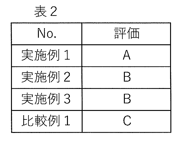
得られた光応答性組成物について、以下の評価を行った。結果を表2に示す。
各光応答性組成物について、作成直後と5分後に発光ピーク波長を測定した。測定条件と評価基準を以下に示す。
測定装置:絶対PL量子収率測定装置C9920-03(浜松ホトニクス社製)
励起光波長:460nm
励起光積分範囲:励起光波長±10nm
発光積分範囲:(励起光波長+20)nm~770nm
作成直後と5分後で、500nm~600nmの範囲において発光が最大値となる波長の差の絶対値を算出し、以下の基準により評価した。
A:上記波長の差の絶対値が0nm以上20nm未満
B:上記波長の差の絶対値が20nm以上50nm未満
C:上記波長の差の絶対値が50nm以上
媒体と、
光応答性を有するペロブスカイト型の結晶構造を有する第1のナノ粒子と、第1の有機基と前記第1のナノ粒子に配位する第1の結合部とを有し前記第1のナノ粒子を保護する第1の保護層と、前記媒体と前記第1の保護層との間に位置し前記第1の粒子を保護する第3の保護層と、を含み前記媒体に支持される第1の粒子と、
前記第1のナノ粒子と異なる組成を有するペロブスカイト型の結晶構造を有する第2のナノ粒子と、第2の有機基と前記第2のナノ粒子に配位する結合部とを有し前記第2のナノ粒子を保護する第2の保護層と、を含み前記媒体に支持される第2の粒子と、
を備える光応答性組成物。
前記第3の保護層は、第3の有機基を側鎖に有する高分子を含有する構成1に関わる光応答性組成物。
前記第1の保護層は前記第3の保護層に接し、前記第2の保護層は前記第3の保護層に接しない構成1または2に関わる光応答性組成物。
前記第1の保護層は、前記第3の保護層により保護される構成1または2に関わる光応答性組成物。
前記第3の保護層は、前記第1の粒子を内包する一方で、前記第2の粒子を内包しない構成1~4のいずれかに関わる光応答性組成物。
前記第3の保護層は、紫外および青色の少なくともいずれかを含む第1の波長帯域と前記第1のナノ粒子の発光波長に係る第2の波長帯域と、において、それぞれ、前記第1のナノ粒子より低い吸光度を有する構成1~5のいずれかに関わる光応答性組成物。
前記媒体は、重合性化合物を含む構成1~6のいずれかに関わる光応答性組成物。
前記媒体は、溶媒を含む構成7に関わる光応答性組成物。
前記媒体は、前記第1の粒子と前記第2の粒子とがそれぞれ分散されるポリマーマトリクスを含む構成1~8のいずれかに関わる光応答性組成物。
前記媒体は、シート状の固体である構成9に関わる光応答性組成物。
前記第2の粒子は、前記媒体と前記第2の保護層との間に位置し、前記第2の粒子を保護する第4の保護層を備える構成1に関わる光応答性組成物。
前記第4の保護層は、第4の有機基を側鎖に有する高分子を含有する構成11に関わる光応答性組成物。
前記第2の保護層は前記第4の保護層に接し、前記第1の保護層は前記第4の保護層に接しない構成11または12に関わる光応答性組成物。
前記第2の保護層は、前記第4の保護層により保護される構成11~13のいずれかに関わる光応答性組成物。
前記第4の保護層は、前記第2の粒子を内包する一方で、前記第1の粒子を内包しない請求項11~14のいずれかに関わる光応答性組成物。
前記第4の保護層は、紫外および青色の少なくともいずれかを含む第1の波長帯域と前記第2のナノ粒子の発光波長に係る第3の波長帯域と、において、それぞれ、前記第1のナノ粒子より低い吸光度を有する構成11~15のいずれかに関わる光応答性組成物。
前記第1の粒子は、緑色および赤色のうちいずれか一方を多く発光する発光特性を呈し、前記第2の粒子は、緑色および赤色のうちいずれか他方を多く発光する発光特性を呈する構成1~16のいずれかに関わる光応答性組成物。
前記第1の粒子は、臭素およびヨウ素のうちいずれか一方を多く含有し、前記第2の粒子は、臭素およびヨウ素のうちいずれか他方を多く含有する構成1~17のいずれかに関わる光応答性組成物。
20 第1の保護層
30 第1粒子
40 第2のナノ粒子
50 第2の保護層
60 第2粒子
70 媒体
80 第3の保護層
90 第4の保護層
110 第1の結合部
120 第1の有機基
150 重合性化合物
160 重合体
100、200、300 光応答性組成物
Claims (18)
- 媒体と、
光応答性を有するペロブスカイト型の結晶構造を有する第1のナノ粒子と、第1の有機基と前記第1のナノ粒子に配位する第1の結合部とを有し前記第1のナノ粒子を保護する第1の保護層と、前記媒体と前記第1の保護層との間に位置し前記第1の粒子を保護する第3の保護層と、を含み前記媒体に支持される第1の粒子と、
前記第1のナノ粒子と異なる組成を有するペロブスカイト型の結晶構造を有する第2のナノ粒子と、第2の有機基と前記第2のナノ粒子に配位する結合部とを有し前記第2のナノ粒子を保護する第2の保護層と、を含み前記媒体に支持される第2の粒子と、
を備える光応答性組成物。 - 前記第3の保護層は、第3の有機基を側鎖に有する高分子を含有する請求項1に記載の光応答性組成物。
- 前記第1の保護層は前記第3の保護層に接し、前記第2の保護層は前記第3の保護層に接しない請求項1または2に記載の光応答性組成物。
- 前記第1の保護層は、前記第3の保護層により保護される請求項1または2に記載の光応答性組成物。
- 前記第3の保護層は、前記第1の粒子を内包する一方で、前記第2の粒子を内包しない請求項1または2に記載の光応答性組成物。
- 前記第3の保護層は、紫外および青色の少なくともいずれかを含む第1の波長帯域と前記第1のナノ粒子の発光波長に係る第2の波長帯域と、において、それぞれ、前記第1のナノ粒子より低い吸光度を有する請求項1または2に記載の光応答性組成物。
- 前記媒体は、重合性化合物を含む請求項1または2に記載の光応答性組成物。
- 前記媒体は、溶媒を含む請求項7に記載の光応答性組成物。
- 前記媒体は、前記第1の粒子と前記第2の粒子とがそれぞれ分散されるポリマーマトリクスを含む請求項1または2に記載の光応答性組成物。
- 前記媒体は、シート状の固体である請求項9に記載の光応答性組成物。
- 前記第2の粒子は、前記媒体と前記第2の保護層との間に位置し、前記第2の粒子を保護する第4の保護層を備える請求項1に記載の光応答性組成物。
- 前記第4の保護層は、第4の有機基を側鎖に有する高分子を含有する請求項11に記載の光応答性組成物。
- 前記第2の保護層は前記第4の保護層に接し、前記第1の保護層は前記第4の保護層に接しない請求項11または12に記載の光応答性組成物。
- 前記第2の保護層は、前記第4の保護層により保護される請求項11または12に記載の光応答性組成物。
- 前記第4の保護層は、前記第2の粒子を内包する一方で、前記第1の粒子を内包しない請求項1または2に記載の光応答性組成物。
- 前記第4の保護層は、紫外および青色の少なくともいずれかを含む第1の波長帯域と前記第2のナノ粒子の発光波長に係る第3の波長帯域と、において、それぞれ、前記第1のナノ粒子より低い吸光度を有する請求項11または12に記載の光応答性組成物。
- 前記第1の粒子は、緑色および赤色のうちいずれか一方を多く発光する発光特性を呈し、前記第2の粒子は、緑色および赤色のうちいずれか他方を多く発光する発光特性を呈する請求項1または2に記載の光応答性組成物。
- 前記第1の粒子は、臭素およびヨウ素のうちいずれか一方を多く含有し、前記第2の粒子は、臭素およびヨウ素のうちいずれか他方を多く含有する請求項1または2に記載の光応答性組成物。
Priority Applications (3)
| Application Number | Priority Date | Filing Date | Title |
|---|---|---|---|
| KR1020257034746A KR20250163950A (ko) | 2023-03-28 | 2024-03-11 | 광 응답성 조성물 |
| CN202480021437.5A CN121002143A (zh) | 2023-03-28 | 2024-03-11 | 光响应性组合物 |
| US19/337,635 US20260015542A1 (en) | 2023-03-28 | 2025-09-23 | Photoresponsive composition |
Applications Claiming Priority (2)
| Application Number | Priority Date | Filing Date | Title |
|---|---|---|---|
| JP2023052461A JP2024141032A (ja) | 2023-03-28 | 2023-03-28 | 光応答性組成物 |
| JP2023-052461 | 2023-03-28 |
Related Child Applications (1)
| Application Number | Title | Priority Date | Filing Date |
|---|---|---|---|
| US19/337,635 Continuation US20260015542A1 (en) | 2023-03-28 | 2025-09-23 | Photoresponsive composition |
Publications (1)
| Publication Number | Publication Date |
|---|---|
| WO2024203201A1 true WO2024203201A1 (ja) | 2024-10-03 |
Family
ID=92904324
Family Applications (1)
| Application Number | Title | Priority Date | Filing Date |
|---|---|---|---|
| PCT/JP2024/009260 Ceased WO2024203201A1 (ja) | 2023-03-28 | 2024-03-11 | 光応答性組成物 |
Country Status (5)
| Country | Link |
|---|---|
| US (1) | US20260015542A1 (ja) |
| JP (1) | JP2024141032A (ja) |
| KR (1) | KR20250163950A (ja) |
| CN (1) | CN121002143A (ja) |
| WO (1) | WO2024203201A1 (ja) |
Citations (3)
| Publication number | Priority date | Publication date | Assignee | Title |
|---|---|---|---|---|
| WO2020235420A1 (ja) * | 2019-05-21 | 2020-11-26 | Dic株式会社 | 発光粒子の製造方法、発光粒子、発光粒子分散体、インク組成物および発光素子 |
| JP2021091870A (ja) * | 2019-11-29 | 2021-06-17 | 東洋インキScホールディングス株式会社 | 発光材料、発光材料組成物、発光変換部材、バックライトユニット、及び液晶表示装置 |
| WO2023100937A1 (ja) * | 2021-11-30 | 2023-06-08 | キヤノン株式会社 | 光応答性材料および光応答性組成物 |
Family Cites Families (2)
| Publication number | Priority date | Publication date | Assignee | Title |
|---|---|---|---|---|
| JP2018197782A (ja) | 2017-05-23 | 2018-12-13 | Dic株式会社 | 光変換フィルムおよびそれを用いた液晶表示素子 |
| EP3753994B1 (en) | 2019-06-17 | 2021-06-23 | Avantama AG | Luminescent component |
-
2023
- 2023-03-28 JP JP2023052461A patent/JP2024141032A/ja active Pending
-
2024
- 2024-03-11 WO PCT/JP2024/009260 patent/WO2024203201A1/ja not_active Ceased
- 2024-03-11 KR KR1020257034746A patent/KR20250163950A/ko active Pending
- 2024-03-11 CN CN202480021437.5A patent/CN121002143A/zh active Pending
-
2025
- 2025-09-23 US US19/337,635 patent/US20260015542A1/en active Pending
Patent Citations (3)
| Publication number | Priority date | Publication date | Assignee | Title |
|---|---|---|---|---|
| WO2020235420A1 (ja) * | 2019-05-21 | 2020-11-26 | Dic株式会社 | 発光粒子の製造方法、発光粒子、発光粒子分散体、インク組成物および発光素子 |
| JP2021091870A (ja) * | 2019-11-29 | 2021-06-17 | 東洋インキScホールディングス株式会社 | 発光材料、発光材料組成物、発光変換部材、バックライトユニット、及び液晶表示装置 |
| WO2023100937A1 (ja) * | 2021-11-30 | 2023-06-08 | キヤノン株式会社 | 光応答性材料および光応答性組成物 |
Also Published As
| Publication number | Publication date |
|---|---|
| KR20250163950A (ko) | 2025-11-21 |
| CN121002143A (zh) | 2025-11-21 |
| JP2024141032A (ja) | 2024-10-10 |
| US20260015542A1 (en) | 2026-01-15 |
Similar Documents
| Publication | Publication Date | Title |
|---|---|---|
| JP7631287B2 (ja) | インク組成物 | |
| JP2025100589A (ja) | 光応答性材料および光応答性組成物 | |
| KR102713384B1 (ko) | 양자점 집단과 이를 포함하는 조성물 | |
| KR101900056B1 (ko) | 양자점 폴리머 필름 제조 방법 | |
| JP7574889B2 (ja) | 半導体ナノ粒子複合体、半導体ナノ粒子複合体分散液、半導体ナノ粒子複合体組成物および半導体ナノ粒子複合体硬化膜 | |
| JP2021091870A (ja) | 発光材料、発光材料組成物、発光変換部材、バックライトユニット、及び液晶表示装置 | |
| JP2025032158A (ja) | 半導体ナノ粒子複合体、半導体ナノ粒子複合体分散液、半導体ナノ粒子複合体組成物、半導体ナノ粒子複合体硬化膜、および半導体ナノ粒子複合体パターニング膜 | |
| KR20220020279A (ko) | 반도체 나노 입자 복합체, 반도체 나노 입자 복합체 분산액, 반도체 나노 입자 복합체 조성물 및 반도체 나노 입자 복합체 경화막 | |
| JP7327151B2 (ja) | 発光材料、発光材料組成物、発光変換部材、バックライトユニット、及び液晶表示装置 | |
| WO2024203201A1 (ja) | 光応答性組成物 | |
| KR102558920B1 (ko) | 페로브스카이트 나노입자-고분자 복합체의 제조방법 및 이를 통하여 제조된 페로브스카이트 나노입자-고분자 복합체 | |
| WO2024241904A1 (ja) | ナノ粒子の精製方法、ナノ粒子組成物、および、ナノ粒子組成物の製造方法 | |
| JP6973469B2 (ja) | 半導体ナノ粒子集合体、半導体ナノ粒子集合体分散液、半導体ナノ粒子集合体組成物及び半導体ナノ粒子集合体硬化膜 | |
| JP6973470B2 (ja) | 半導体ナノ粒子集合体、半導体ナノ粒子集合体分散液、半導体ナノ粒子集合体組成物及び半導体ナノ粒子集合体硬化膜 | |
| JP2024166934A (ja) | エネルギー応答性組成物の製造方法、エネルギー応答性組成物 | |
| CN117642472A (zh) | Ksf-油墨 | |
| CN118647688A (zh) | 光响应性材料和光响应性组合物 |
Legal Events
| Date | Code | Title | Description |
|---|---|---|---|
| 121 | Ep: the epo has been informed by wipo that ep was designated in this application |
Ref document number: 24779332 Country of ref document: EP Kind code of ref document: A1 |
|
| WWE | Wipo information: entry into national phase |
Ref document number: CN2024800214375 Country of ref document: CN |
|
| ENP | Entry into the national phase |
Ref document number: 1020257034746 Country of ref document: KR Free format text: ST27 STATUS EVENT CODE: A-0-1-A10-A15-NAP-PA0105 (AS PROVIDED BY THE NATIONAL OFFICE) |
|
| WWE | Wipo information: entry into national phase |
Ref document number: KR1020257034746 Country of ref document: KR Ref document number: 1020257034746 Country of ref document: KR |
|
| NENP | Non-entry into the national phase |
Ref country code: DE |
|
| 122 | Ep: pct application non-entry in european phase |
Ref document number: 24779332 Country of ref document: EP Kind code of ref document: A1 |