WO2024202193A1 - 生体情報計測装置、及び生体情報計測システム - Google Patents
生体情報計測装置、及び生体情報計測システム Download PDFInfo
- Publication number
- WO2024202193A1 WO2024202193A1 PCT/JP2023/040736 JP2023040736W WO2024202193A1 WO 2024202193 A1 WO2024202193 A1 WO 2024202193A1 JP 2023040736 W JP2023040736 W JP 2023040736W WO 2024202193 A1 WO2024202193 A1 WO 2024202193A1
- Authority
- WO
- WIPO (PCT)
- Prior art keywords
- electrode
- contact
- biological information
- contact state
- display
- Prior art date
- Legal status (The legal status is an assumption and is not a legal conclusion. Google has not performed a legal analysis and makes no representation as to the accuracy of the status listed.)
- Ceased
Links
Images


Classifications
-
- A—HUMAN NECESSITIES
- A61—MEDICAL OR VETERINARY SCIENCE; HYGIENE
- A61B—DIAGNOSIS; SURGERY; IDENTIFICATION
- A61B5/00—Measuring for diagnostic purposes; Identification of persons
- A61B5/68—Arrangements of detecting, measuring or recording means, e.g. sensors, in relation to patient
- A61B5/6801—Arrangements of detecting, measuring or recording means, e.g. sensors, in relation to patient specially adapted to be attached to or worn on the body surface
- A61B5/6843—Monitoring or controlling sensor contact pressure
-
- G—PHYSICS
- G01—MEASURING; TESTING
- G01N—INVESTIGATING OR ANALYSING MATERIALS BY DETERMINING THEIR CHEMICAL OR PHYSICAL PROPERTIES
- G01N27/00—Investigating or analysing materials by the use of electric, electrochemical, or magnetic means
- G01N27/26—Investigating or analysing materials by the use of electric, electrochemical, or magnetic means by investigating electrochemical variables; by using electrolysis or electrophoresis
- G01N27/28—Electrolytic cell components
- G01N27/30—Electrodes, e.g. test electrodes; Half-cells
- G01N27/327—Biochemical electrodes, e.g. electrical or mechanical details for in vitro measurements
-
- A—HUMAN NECESSITIES
- A61—MEDICAL OR VETERINARY SCIENCE; HYGIENE
- A61B—DIAGNOSIS; SURGERY; IDENTIFICATION
- A61B5/00—Measuring for diagnostic purposes; Identification of persons
- A61B5/0002—Remote monitoring of patients using telemetry, e.g. transmission of vital signals via a communication network
- A61B5/0015—Remote monitoring of patients using telemetry, e.g. transmission of vital signals via a communication network characterised by features of the telemetry system
- A61B5/002—Monitoring the patient using a local or closed circuit, e.g. in a room or building
-
- A—HUMAN NECESSITIES
- A61—MEDICAL OR VETERINARY SCIENCE; HYGIENE
- A61B—DIAGNOSIS; SURGERY; IDENTIFICATION
- A61B5/00—Measuring for diagnostic purposes; Identification of persons
- A61B5/24—Detecting, measuring or recording bioelectric or biomagnetic signals of the body or parts thereof
- A61B5/25—Bioelectric electrodes therefor
- A61B5/26—Bioelectric electrodes therefor maintaining contact between the body and the electrodes by the action of the subjects, e.g. by placing the body on the electrodes or by grasping the electrodes
-
- A—HUMAN NECESSITIES
- A61—MEDICAL OR VETERINARY SCIENCE; HYGIENE
- A61B—DIAGNOSIS; SURGERY; IDENTIFICATION
- A61B5/00—Measuring for diagnostic purposes; Identification of persons
- A61B5/72—Signal processing specially adapted for physiological signals or for diagnostic purposes
- A61B5/7235—Details of waveform analysis
- A61B5/7264—Classification of physiological signals or data, e.g. using neural networks, statistical classifiers, expert systems or fuzzy systems
-
- G—PHYSICS
- G01—MEASURING; TESTING
- G01N—INVESTIGATING OR ANALYSING MATERIALS BY DETERMINING THEIR CHEMICAL OR PHYSICAL PROPERTIES
- G01N27/00—Investigating or analysing materials by the use of electric, electrochemical, or magnetic means
- G01N27/26—Investigating or analysing materials by the use of electric, electrochemical, or magnetic means by investigating electrochemical variables; by using electrolysis or electrophoresis
- G01N27/28—Electrolytic cell components
- G01N27/30—Electrodes, e.g. test electrodes; Half-cells
- G01N27/301—Reference electrodes
-
- A—HUMAN NECESSITIES
- A61—MEDICAL OR VETERINARY SCIENCE; HYGIENE
- A61B—DIAGNOSIS; SURGERY; IDENTIFICATION
- A61B5/00—Measuring for diagnostic purposes; Identification of persons
- A61B5/0002—Remote monitoring of patients using telemetry, e.g. transmission of vital signals via a communication network
- A61B5/0004—Remote monitoring of patients using telemetry, e.g. transmission of vital signals via a communication network characterised by the type of physiological signal transmitted
- A61B5/0006—ECG or EEG signals
-
- A—HUMAN NECESSITIES
- A61—MEDICAL OR VETERINARY SCIENCE; HYGIENE
- A61B—DIAGNOSIS; SURGERY; IDENTIFICATION
- A61B5/00—Measuring for diagnostic purposes; Identification of persons
- A61B5/24—Detecting, measuring or recording bioelectric or biomagnetic signals of the body or parts thereof
- A61B5/25—Bioelectric electrodes therefor
- A61B5/276—Protection against electrode failure
-
- A—HUMAN NECESSITIES
- A61—MEDICAL OR VETERINARY SCIENCE; HYGIENE
- A61B—DIAGNOSIS; SURGERY; IDENTIFICATION
- A61B5/00—Measuring for diagnostic purposes; Identification of persons
- A61B5/24—Detecting, measuring or recording bioelectric or biomagnetic signals of the body or parts thereof
- A61B5/316—Modalities, i.e. specific diagnostic methods
- A61B5/318—Heart-related electrical modalities, e.g. electrocardiography [ECG]
- A61B5/332—Portable devices specially adapted therefor
Definitions
- the present invention belongs to the field of healthcare-related technology, and in particular relates to bioinformation measuring devices and bioinformation measuring systems.
- biometric information blood pressure and electrocardiogram waveforms
- a portable electrocardiogram measuring device e.g., Patent Document 1
- Patent Document 1 a portable electrocardiogram measuring device that immediately measures electrocardiogram waveforms when abnormalities such as chest pain or palpitations occur in daily life, and is expected to contribute to the early detection of heart disease and appropriate treatment.
- Patent Document 1 discloses that in a portable electrocardiogram recording device that measures and records electrocardiogram waveforms using a pair of electrodes that are placed in contact with the skin of the right hand and chest, an electrical circuit detects whether the contact resistance between the skin and the electrodes is sufficiently small, and if the contact resistance is not sufficiently small, the person being measured is notified of poor contact by a display, sound, etc.
- the person taking the measurement can be notified of this condition, and the person taking the measurement can take measures such as repositioning the electrodes or applying water, and then a normal electrocardiogram can be recorded.
- the present invention aims to provide a technique that can notify the contact state between the electrodes and the measurement subject in three or more levels when measuring bioinformation using a bioinformation measuring device equipped with electrodes.
- a biological information measuring device comprising a first electrode, a second electrode, and a third electrode, the biological information measuring device measuring biological information of a measurement target based on a potential difference between the first electrode and the second electrode, the potential of the third electrode being set as a reference potential, a first contact signal output means for outputting a signal related to a contact state of the first electrode with the measurement target based on a potential of the first electrode that varies depending on a contact state of the first electrode with the measurement target; a second contact signal output means for outputting a signal related to a contact state of the second electrode with the measurement target based on a potential of the second electrode that varies depending on a contact state of the second electrode with the measurement target; a contact state classification means for classifying the levels of the contact states of the first electrodes and the second electrodes with respect to the measurement target into at least three levels based on the signals output by the first contact detection means and the second contact detection means; a notification means
- the contact state between the first electrode and the second electrode and the contact object can be displayed in three or more levels, and the user can intuitively grasp how much pressure to use to adjust the contact state between each electrode and the skin depending on the current level of the electrode contact state.
- the notification means may also include audio output means and may be configured to notify by audio.
- the notification means may also include vibration means and may be configured to notify by vibration.
- the notification means may also include display means and may be configured to notify by display. Depending on the environment in which the device is used, the characteristics of the user, and the timing of the notification, there are various ways in which the contact state information should be perceived, and it is desirable to be able to notify by various output methods.
- the notification means may indicate the level by at least one of the following on the display means: a numerical value, a number of display segments whose display is activated, a size of an area whose display is activated, or differences in color and transparency of the display area. This allows the user to easily grasp the level of contact between each electrode and the skin.
- the notification means may also notify the contact state of each of the first electrode and the second electrode with respect to the measurement subject before and/or during the measurement process of the biological information.
- the notification means may also notify the contact state of each of the first electrode and the second electrode with respect to the measurement subject before and/or during the measurement process of the biological information.
- the present invention can also be understood as a biological information measuring system as follows.
- a bioinformation measuring system including a bioinformation measuring device including a first electrode, a second electrode, and a third electrode, the bioinformation measuring device measuring bioinformation of a measurement target based on a potential difference between the first electrode and the second electrode with a potential of the third electrode as a reference potential, and an information processing terminal communicating with the bioinformation measuring device
- the biological information measuring device includes: A control means for executing a process of measuring the biological information; a first contact detection means for outputting a signal related to a contact state of the first electrode with the measurement target based on a potential of the first electrode that varies depending on a contact state of the first electrode with the measurement target; a second contact detection means for outputting a signal relating to a contact state of the second electrode with the measurement target based on a potential of the second electrode that varies depending on a contact state of the second electrode with the measurement target; At least one of the bioinformation measuring device and the information processing terminal, a contact state
- the degree of freedom in the manner of notification can be increased, making it possible to provide notifications with higher usability.
- the notification means may include a display means and may provide notification by display.
- the notification means may indicate the level by at least one of the following: a numerical value displayed on the display means, a number of display segments whose display is activated, a size of an area whose display is activated, or differences in color and transparency of a display area.
- the notification means may also provide notification of the contact state of each of the first electrode and the second electrode with respect to the measurement target before and/or during the measurement process of the bioinformation.
- the contact state between the electrodes and the measurement subject can be notified in three or more levels.
- FIG. 1 is a schematic diagram illustrating an overview of a biological information measuring system according to a first embodiment.
- Fig. 2A is a front view showing the configuration of the portable electrocardiograph according to embodiment 1.
- Fig. 2B is a rear view showing the configuration of the portable electrocardiograph according to embodiment 1.
- Fig. 2C is a left side view showing the configuration of the portable electrocardiograph according to embodiment 1.
- Fig. 2D is a right side view showing the configuration of the portable electrocardiograph according to embodiment 1.
- Fig. 2E is a plan view showing the configuration of the portable electrocardiograph according to embodiment 1.
- Fig. 2F is a bottom view showing the configuration of the portable electrocardiograph according to embodiment 1.
- FIG. 2A is a front view showing the configuration of the portable electrocardiograph according to embodiment 1.
- Fig. 2B is a rear view showing the configuration of the portable electrocardiograph according to embodiment 1.
- Fig. 2C is a left side view showing the configuration of the portable electrocardiograph according to embodiment 1.
- FIG. 3 is a circuit diagram showing an outline of an electric circuit including each electrode of the portable electrocardiograph according to the first embodiment.
- FIG. 4 is a flowchart showing a part of the flow of each process when the portable electrocardiograph and the smartphone are communicatively connected in the biological information measuring system according to the first embodiment.
- FIG. 5 is a flowchart showing a part of the flow of each process when the portable electrocardiograph and the smartphone are communicatively connected in the biological information measuring system according to the first embodiment.
- FIG. 6 is a flowchart showing a part of the flow of each process when the portable electrocardiograph and the smartphone are communicatively connected in the biological information measuring system according to the first embodiment.
- FIG. 4 is a flowchart showing a part of the flow of each process when the portable electrocardiograph and the smartphone are communicatively connected in the biological information measuring system according to the first embodiment.
- FIG. 5 is a flowchart showing a part of the flow of each process when the portable electrocardiograph and the smartphone are commun
- FIG. 7 is a flowchart showing a subroutine of processing when the portable electrocardiograph according to the first embodiment performs BLE communication.
- Fig. 8A is a first diagram showing an example of a display of an electrode contact level in the biological information measuring system according to embodiment 1.
- Fig. 8B is a second diagram showing an example of a display of an electrode contact level in the biological information measuring system according to embodiment 1.
- Fig. 8C is a third diagram showing an example of a display of an electrode contact level in the biological information measuring system according to embodiment 1.
- Fig. 9A is a first diagram showing an example of a screen displayed on a smartphone during electrocardiogram measurement in the bioinformation measurement system according to embodiment 1.
- Fig. 9A is a first diagram showing an example of a screen displayed on a smartphone during electrocardiogram measurement in the bioinformation measurement system according to embodiment 1.
- Fig. 9A is a first diagram showing an example of a screen displayed on a smartphone during electrocardiogram measurement in the bioinformation measurement system according to embodiment 1.
- FIG. 9B is a second diagram showing an example of a screen displayed on a smartphone during electrocardiogram measurement in the bioinformation measurement system according to embodiment 1.
- Fig. 9C is a third diagram showing an example of a screen displayed on a smartphone during electrocardiogram measurement in the bioinformation measurement system according to embodiment 1.
- Fig. 9D is a fourth diagram showing an example of a screen displayed on a smartphone during electrocardiogram measurement in the bioinformation measurement system according to embodiment 1.
- Fig. 10A is a first diagram showing a modified example of the display of the electrode contact level in the bioinformation measuring system according to embodiment 1.
- Fig. 10B is a second diagram showing a modified example of the display of the electrode contact level in the bioinformation measuring system according to embodiment 1.
- FIG. 10C is a third diagram showing a modified example of the display of the electrode contact level in the bioinformation measuring system according to embodiment 1.
- Fig. 11A is a front view showing the configuration of the portable electrocardiograph according to embodiment 2.
- Fig. 11B is a rear view showing the configuration of the portable electrocardiograph according to embodiment 2.
- Fig. 11C is a left side view showing the configuration of the portable electrocardiograph according to embodiment 2.
- Fig. 11D is a right side view showing the configuration of the portable electrocardiograph according to embodiment 2.
- Fig. 11E is a plan view showing the configuration of the portable electrocardiograph according to embodiment 2.
- Fig. 11F is a bottom view showing the configuration of the portable electrocardiograph according to embodiment 2.
- FIG. 12 is a block diagram showing the functional configuration of the portable electrocardiograph according to the second embodiment.
- FIG. 13 is a flowchart showing the flow of electrocardiogram waveform measurement processing in the portable electrocardiograph according to the second embodiment.
- FIG. 1 is a schematic diagram showing an example of the configuration of a bioinformation measuring system 1 according to the present embodiment.
- the bioinformation measuring system 1 includes a portable electrocardiograph 10 as an example of a bioinformation measuring device, and a smartphone 20 as an example of an information processing terminal, which are configured to be communicatively connected to each other.
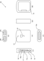
- FIG. 2 is a diagram showing the configuration of the portable electrocardiograph 10 in this embodiment.
- Fig. 2A is a front view showing the front of the main body
- Fig. 2B is a rear view
- Fig. 2C is a left side view
- Fig. 2D is a right side view
- Fig. 2E is a plan view
- Fig. 2F is a bottom view.
- the bottom surface of the portable electrocardiograph 10 is provided with a left-side electrode 12a that is brought into contact with the left side of the body during electrocardiogram measurement, and on the upper surface of the opposite side, a first right-side electrode 12b that is brought into contact with the middle joint of the index finger of the right hand, and a second right-side electrode 12c that is brought into contact with the proximal joint of the index finger of the right hand are similarly provided.
- the first right-side electrode 12b is an electrode that functions as a GND electrode.
- the user When measuring electrocardiograms, the user holds the portable electrocardiograph 10 in his right hand and places the index finger of his right hand on the top surface of the portable electrocardiograph 10 so that it properly contacts the first right-side electrode 12b and the second right-side electrode 12c.
- the left-side electrode 12a is then brought into contact with the skin at a position corresponding to the desired measurement method.
- the left-side electrode 12a when measuring with the so-called I lead, the left-side electrode 12a is placed on the palm of the left hand and brought into contact, and when measuring with the so-called V4 lead, the left-side electrode 12a is brought into contact with the skin slightly to the left of the epigastric region of the left chest and below the nipple.
- the portable electrocardiograph 10 Various operating sections and indicators are arranged on the left side of the portable electrocardiograph 10. Specifically, it is equipped with a power switch 16, a power LED 16a, a BLE (Bluetooth (registered trademark) Low Energy) communication button 17, a BLE communication LED 17a, a remaining memory display LED 18, a battery replacement LED 19, etc.
- a power switch 16 a power LED 16a
- BLE communication LED 17a a BLE communication LED 17a
- remaining memory display LED 18 a battery replacement LED 19, etc.
- a measurement status notification LED 13 and an analysis result notification LED 14 are provided on the front of the portable electrocardiograph 10, and a battery storage port and a battery cover 15 are located on the back of the portable electrocardiograph 10.
- FIG. 1 also shows a block diagram showing the functional configuration of the portable electrocardiograph 10.
- the portable electrocardiograph 10 is configured to include the following functional units: a control unit 101, an electrode unit 12, an amplifier unit 102, an A/D (Analog to Digital) conversion unit 103, a timer unit 104, a memory unit 105, a display unit 106, an operation unit 107, a power supply unit 108, a communication unit 109, a contact detection unit 111, and an A/D conversion unit 112.
- the control unit 101 is a means for controlling the portable electrocardiograph 10, and is configured to include, for example, a CPU (Central Processing Unit).
- a CPU Central Processing Unit
- the control unit 101 receives a user's operation via the operation unit 107, it controls each component of the portable electrocardiograph 10 to execute various processes such as electrocardiogram measurement and information communication according to a predetermined program.
- the predetermined program is stored in the memory unit 105, which will be described later, and is read from there.
- the control unit 101 also includes, as functional modules, an analysis unit 110 that analyzes electrocardiogram waveforms, and a contact state classification unit 113.
- the analysis unit 110 analyzes the measured electrocardiogram waveform for the presence or absence of waveform disturbances, and outputs a result indicating whether or not the electrocardiogram waveform at least at the time of measurement is normal.
- the contact state classification unit 113 also classifies the level of the contact state of the left electrode 12a and the first right electrode 12b detected by the contact detection unit 111 into four levels. The detection of the contact state and its level classification will be described later.
- the electrode unit 12 is composed of a left electrode 12a, a first right electrode 12b, and a second right electrode 12c, and functions as a sensor that detects an electrocardiogram waveform.
- the second right electrode 12c is used as a ground (GND) electrode, and the potential difference between the potential of the left electrode 12a and the potential of the first right electrode 12b relative to the reference potential is continuously measured to obtain an electrocardiogram waveform.
- GND ground
- the amplifier unit 102 has a function of amplifying a signal indicating an electrocardiogram waveform output from the electrode unit 12 as described below.
- the A/D conversion unit 103 has a function of converting the analog signal amplified by the amplifier unit 102 into a digital signal and transmitting it to the control unit 101.
- the timer unit 104 has a function of measuring time by referring to an RTC (Real Time Clock). For example, as described below, when performing electrode contact detection processing, it counts the time that all of the left electrode 12a, the first right electrode 12b, and the second right electrode 12c are in contact with the body. It may also count the time until the measurement is completed during electrocardiogram measurement and output this.
- RTC Real Time Clock
- the storage unit 105 includes a main storage device such as a RAM (Random Access Memory) or a ROM (Read Only Memory), and stores various information such as application programs, measured electrocardiogram waveforms, and analysis results.
- a main storage device such as a RAM (Random Access Memory) or a ROM (Read Only Memory)
- various information such as application programs, measured electrocardiogram waveforms, and analysis results.
- the storage unit 105 also includes a long-term storage medium such as a flash memory.
- the display unit 106 includes a measurement status notification LED 13, an analysis result notification LED 14, a power supply LED 16a, a BLE communication LED 17a, a remaining memory indication LED 18, a battery replacement LED 19, etc., and communicates the device status to the user by turning on or blinking the LEDs.
- the operation unit 107 includes a power supply switch 16, a communication button 17, etc., and has the function of accepting input operations from the user and causing the control unit 101 to execute processing according to the operation.
- the power supply unit 108 includes a battery that supplies the power necessary to operate the device.
- the battery may be a secondary battery such as a lithium ion battery, or a primary battery.
- the communication unit 109 includes an antenna for wireless communication, and has a function of communicating with other devices such as an information processing terminal (described later) at least via BLE communication. It may also be provided with a terminal for wired communication.
- the contact detection unit 111 includes an electrical circuit connected to the left electrode 12a and the first right electrode 12b, detects the contact state between the left electrode 12a and the first right electrode 12b and the skin surface of the measurement target, and outputs a signal according to the level of the contact state.
- the A/D conversion unit 112 converts the analog signal output by the contact detection unit 111 into a digital signal and transmits it to the control unit 101.
- Fig. 3 is a circuit diagram showing an outline of an electric circuit including each electrode of the portable electrocardiograph 10.
- the second right-side electrode 12c is connected to the reference potential GND and functions as a ground electrode.
- the first right-side electrode 12b is connected to the power supply potential V1 via a right-side pull-up resistor 911.
- the left-side electrode 12a is connected to the power supply potential V1 via a left-side pull-up resistor 921.
- the power supply potential V1 is set to a potential (e.g., 4 V) that is higher than the reference potential GND and ensures a sufficient bias.
- the circuit shown by the dashed line in Figure 3 indicates the path of the current via the impedance of the human body.
- the right pull-up resistor 911 and the left pull-up resistor 921 are set to a sufficiently high resistance value (e.g., 200 M ⁇ , preferably 300 M ⁇ or more) to ensure the accuracy of the detected electrocardiogram waveform.
- a sufficiently high resistance value e.g. 200 M ⁇ , preferably 300 M ⁇ or more
- the circuit shown in FIG. 3 also includes five amplifiers: a right non-inverting amplifier 912, a right buffer amplifier 913, a left non-inverting amplifier 922, a left buffer amplifier 923, and a differential amplifier 94.
- the potential of the first right-side electrode 12b is input to the + input terminal of the right-side non-inverting amplifier 912.
- the right-side amplified signal amplified by an amplification factor defined by the first amplification factor determining resistor 931 and the third amplification factor determining resistor 933 is output from the output terminal of the right-side non-inverting amplifier 912 and input to the - terminal of the differential amplifier 94.
- a signal of the same potential as that input to the + input terminal of the right-side non-inverting amplifier 912 is input to the + input terminal of the right-side buffer amplifier 913 via the right-side non-inverting amplifier 912.
- the right-side non-inverting amplifier 912 functions as a normal amplifier (signal amplifier) and also as a buffer (voltage follower).
- the right buffer amplifier 913 functions as a buffer, and outputs from its output terminal a signal with the same potential as the potential input to the + input terminal.
- the output signal is input to the A/D conversion unit 112 as the right contact state signal 915, converted into a digital signal, and transmitted to the control unit 101.
- the potential of the left electrode 12a is input to the + input terminal of the left non-inverting amplifier 922.
- the left amplified signal amplified by the amplification factor defined by the second amplification factor determining resistor 932 and the third amplification factor determining resistor 933 is output from the output terminal of the left non-inverting amplifier 922 and input to the + terminal of the differential amplifier 94.
- a signal of the same potential as that input to the + input terminal of the left non-inverting amplifier 922 is input to the + input terminal of the left buffer amplifier 923 via the left non-inverting amplifier 922.
- the left non-inverting amplifier 922 also functions as a normal amplifier and also as a buffer.
- the resistance values of the first amplification factor determining resistor 931 and the second amplification factor determining resistor 932 are set to the same value.
- the left buffer amplifier 923 functions as a buffer, and a signal with the same potential as the potential input to the + input terminal is output from the output terminal.
- the output signal is input to the A/D conversion unit 112 as the left contact state signal 925, converted into a digital signal, and transmitted to the control unit 101.
- the contact state classification unit 113 which is a functional module of the control unit 101, classifies the level of the contact state with the skin of each of the first right electrode 12b and the left electrode 12a into four levels: "good contact”, “slightly poor contact”, “poor contact”, and “no contact”, using the right contact state signal 915 and the left contact state signal 925 digitally converted by the A/D conversion unit 112.
- the threshold value for classifying the digitized signal can be set appropriately by the user based on the contact resistance and the quality of the electrocardiogram recording.
- the classified contact state level is stored in the memory unit 105. If the right contact state signal 915 and the left contact state signal 925 change over time, the classification of the contact state may change to reflect this, so information indicating the classified contact state level is recorded in the memory unit 105 as time-series data.
- the differential amplifier 94 is a differential amplifier that amplifies and outputs the difference between the potential of the first right electrode 12b, which is amplified and output by the right non-inverting amplifier 912 input to the - input terminal, and the potential of the left electrode 12a, which is amplified and output by the left non-inverting amplifier 922 input to the + input terminal.
- the differential amplifier 94 is included in the amplifier unit 102, and the signal output from the differential amplifier 94 is the electrocardiogram signal to be measured.
- the electrocardiogram signal is further input to the A/D conversion unit 103, and the digitally converted signal is transmitted to the control unit 101, which records it as an electrocardiogram waveform in the memory unit 105.
- the information processing terminal may be, for example, a smartphone 20 equipped with a touch panel display 23.
- the smartphone 20 includes functional units, such as a control unit 21, a communication unit 22, a display unit 231, an operation unit 232, a storage unit 24, an audio output unit 25, and a vibration unit 26.
- the control unit 21 is a means for controlling the smartphone 20, and is configured to include, for example, a CPU, and performs the corresponding functions by executing various programs stored in the memory unit 24.
- the communication unit 22 includes an antenna for wireless communication, and has the function of communicating with other devices such as the portable electrocardiograph 10 and wireless base stations. It may also be equipped with a terminal for wired communication.
- the display unit 231 includes the touch panel display 23 and displays various information.
- the classified contact state level and the like transmitted from the portable electrocardiograph 10 can be displayed on the touch panel display 23.
- the operation unit 232 includes the touch panel display 23 and accepts various inputs from the user via input images.
- the storage unit 24 includes a main storage device such as RAM as well as a long-term storage medium such as a flash memory, and stores various information such as application programs, measured electrocardiogram waveforms, and analysis results.
- the audio output unit 25 includes a speaker (not shown), and when a communication connection with the portable electrocardiograph 10 is established as described below, it can also notify the classified contact condition level sent from the portable electrocardiograph 10 by voice.
- the vibration unit 26 includes a vibrator (not shown), and when a communication connection with the portable electrocardiograph 10 is established as described below, it can also notify the classified contact state level sent from the portable electrocardiograph 10 by vibration (by its pattern).
- the portable electrocardiograph 10 can perform electrocardiogram measurement, analysis of measurement data, and display of analysis results by itself, it can be more convenient to use the portable electrocardiograph 10 by connecting it to an information processing terminal for communication. The following describes the case where the portable electrocardiograph 10 is used by connecting it to a smartphone 20 for communication.
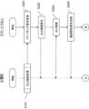
- Figures 4, 5, and 6 are diagrams showing the process flow for electrocardiogram measurement when the portable electrocardiograph 10 and the smartphone 20 are linked via BLE communication, and the timing of information transmission between the devices.
- FIG. 7 is a flowchart showing the flow of the process of the subroutine.
- the control unit 101 of the portable electrocardiograph 10 transmits an advertisement signal for BLE communication from the communication unit 109 (S901).
- the control unit 101 determines whether or not a connection request for BLE communication has been received from another information processing terminal (S902).
- step S903 a BLE connection is made with the device that sent the connection request.
- the control unit 101 ends the subroutine. Note that the trigger for starting this subroutine is not limited to power-on, but may also be, for example, operation of the BLE communication button 17.
- the user sets the smartphone 20 to a state in which BLE communication with the portable electrocardiograph 10 is possible.
- the user operates the touch panel display 23 to turn on the BLE connection setting from a setting menu or the like.
- the BLE connection setting may be turned on by starting up a dedicated application program for linking with the portable electrocardiograph 10.
- the control unit 21 of the smartphone 20 receives an advertising signal for BLE communication via the communication unit 22 (S201) and transmits a BLE connection request to the portable electrocardiograph 10 (S202). Then, the control unit 21 establishes a BLE connection with the portable electrocardiograph 10 (S203, corresponding to S903 above) and transmits a communication start request (S204).
- step S104 If it is determined that a BLE connection has been established, information indicating the level of the electrode contact state (classified) is transmitted to the smartphone 20 (S104), and the smartphone 20 receives the information (S205). If the portable electrocardiograph 10 determines in step S103 that a BLE connection is not established, it skips step S104 and proceeds to step S105, where it performs a process to determine whether the electrode contact state is "good.”
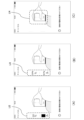
- FIG. 8A to 8C show examples of displays on the touch panel display 23 including information indicating the level of the electrode contact state.
- an image simulating a user undergoing electrocardiogram measurement using the IV lead method with the portable electrocardiograph 10 is displayed on the screen, and an electrode contact level display LI, which is an area indicating the level of the electrode contact state, is displayed on the left side of the screen.
- the electrode contact level display LI is configured such that three display segments indicating the contact level of the first right electrode 12b are displayed on the upper side, and three display segments indicating the contact level of the left electrode 12a are displayed on the lower side.
- the level of contact for each electrode is indicated by the number of activated display segments out of the three. When there are zero activated segments, it means “no contact,” and when all three are activated, it means “good.” When there is only one activated segment, it means “poor contact,” and when there are two, it means “slightly poor contact.”
- the electrode contact level display LI indicates the contact level of each of the first right electrode 12b and the left electrode 12a individually.
- the contact level of the first right electrode 12b indicates “poor contact”
- the contact level of the left electrode 12a indicates “good.”
- the contact level of both electrodes is indicated as "good.”
- the touch panel display 23 may also display information that gives the user advice on how to maintain (or keep) the contact state in a "good” state. For example, as shown in FIG. 8B, when the first right electrode 12b is in a "slightly poor contact” state, the display may read “Please keep the electrode on the finger in close contact,” and as shown in FIG. 8C, when the contact state of all electrodes is "good,” the display may read "Please maintain the current state.”
- the portable electrocardiograph 10 performs a process of determining whether the contact state of both the first right electrode 12b and the left electrode 12a is "good” (S105). If it is determined that the contact state of at least one of the electrodes is not "good”, the process proceeds to step S106, where it is determined whether a predetermined time has elapsed in that state (S106). The predetermined time here is set to an appropriate time (e.g., 5 seconds) to wait for the user to bring the electrode contact state to a "good” state. If the portable electrocardiograph 10 determines in step S106 that the predetermined time has not elapsed, the process returns to step S102 and repeats the subsequent processes. On the other hand, if it is determined in step S106 that the predetermined time has elapsed, the portable electrocardiograph 10 proceeds to step S108.
- the portable electrocardiograph 10 determines in step S105 that the contact state of all electrodes is "good,” it performs processing to determine whether a predetermined time has elapsed in that state (S107).
- the predetermined time here is set to a time (e.g., 3 seconds) appropriate for determining whether the state in which all electrodes are in "good" contact is not transient but is stable. If the portable electrocardiograph 10 determines in step S107 that the predetermined time has not elapsed, it returns to step S102 and repeats the subsequent processing. On the other hand, if it determines in step S107 that the predetermined time has elapsed, it proceeds to step S108.
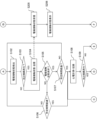
- step S108 the portable electrocardiograph 10 executes electrocardiogram measurement processing and measures and records the electrocardiogram waveform (S108). Specifically, the electrocardiogram signal output from the differential amplifier 94 and input to the control unit 101 via the A/D conversion unit 103 is stored in the storage unit 105 as needed. In addition, following step S108 (actually in parallel), the portable electrocardiograph 10 again executes processing to determine whether or not a BLE connection has been established (S109). If it is determined that a BLE connection has been established, as shown in FIG.
- step S110 information related to electrocardiogram measurement, such as the measured electrocardiogram waveform, the electrode contact state, and the elapsed time from the start of measurement (or the remaining time until the end of measurement), is transmitted to the smartphone 20 (S110), and the information is received by the smartphone 20 (S207).
- the portable electrocardiograph 10 executes processing to determine whether or not a predetermined time (e.g., 30 seconds) for electrocardiogram measurement has elapsed (S111). If the portable electrocardiograph 10 determines in step S109 that a BLE connection is not established, it skips step S110 and proceeds to step S111.
- a predetermined time e.g. 30 seconds
- the smartphone 20 that has received the information related to electrocardiogram measurement displays the information on the touch panel display 23 (S208).
- 9A to 9D show an example of a screen displayed on the touch panel display 23 during the electrocardiogram measurement process.
- the touch panel display displays a number indicating the remaining measurement time (seconds), an electrocardiogram waveform, and an electrode contact level display LI indicating the level of the electrode contact state.
- the seconds are counted down as the measurement time elapses, and the display segments arranged in a circle around the seconds are gradually deactivated.
- the electrode contact level display LI also shows the contact state between the electrodes and the skin in real time, and as shown in FIG.
- step S111 the portable electrocardiograph 10 determines whether a predetermined time for electrocardiographic measurement has elapsed, and if it determines that the time has not elapsed, it returns to step S108 and repeats the subsequent processes. On the other hand, if it determines in step S111 that the predetermined measurement time has elapsed, it executes a process of determining whether a BLE connection has been established (S112). If the portable electrocardiograph 10 determines in step S112 that a BLE connection has not been established, it ends the series of processes. On the other hand, if it determines in step S112 that a BLE connection has been established, the portable electrocardiograph 10 sends a notification to the smartphone 20 that measurement has been completed (S113).
- the smartphone 20 which has received the measurement end notification, sends a BLE communication end request to the portable electrocardiograph 10 (S209), disconnects the BLE connection (S210), and ends the series of processes on the smartphone 20 side.
- various information received by the smartphone 20, such as the electrode contact state and electrocardiogram waveform data can be stored in the storage unit 24 and used as appropriate.
- the portable electrocardiograph 10 and bioinformation measuring system 1 described in this embodiment can automatically detect the contact state between the first right electrode 12b and the left electrode 12a and the skin, and can classify the level of the contact state into stages and show it to the user before and during electrocardiogram measurement.
- an information processing terminal such as a smartphone 20
- the data received by the smartphone 20 can be saved and effectively used using an application program, etc.
- the portable electrocardiograph 10 is capable of measuring and storing electrocardiogram waveforms, detecting, classifying and storing electrode contact levels, analyzing electrocardiogram waveform data, and displaying and storing the analysis results, independent of the smartphone 20, so it is possible to measure electrocardiograms at the desired timing even if communication connection with the smartphone 20 cannot be established.
- the contact level between the skin and each electrode is classified into four stages, but the contact state classification unit 113 may classify the electrode contact level more finely, or may classify into three stages, which is less than four stages.
- the electrode contact level display LI is not limited to activation of the display areas of a plurality of (divided) display segments, and various display modes can be adopted.
- Figures 10A to 10C show modified examples of such an electrode contact level display LI.
- the electrode contact level display LI2 shown in Figure 10A shows the electrode contact level for each of the first right electrode 12b and the left electrode 12a by the size of the area where the display of the continuous bar-like display area is activated.
- the electrode contact level display LI3 shown in FIG. 10B is an example showing the degree of contact for each of the first right electrode 12b and the left electrode 12a as a numerical value (percentage).
- the electrode contact level display LI4 shown in FIG. 10C is an example showing the electrode contact state for each of the first right electrode 12b and the left electrode 12a by color and its transparency.
- the display can be such that the transparency decreases and the color becomes darker when the contact level is high, or the display can be such that the transparency decreases and the color becomes darker as the same contact level continues, and the level of contact is definitively shown when the transparency reaches 0.
- information such as the electrode contact state and electrocardiogram measurement time may be transmitted and received using a transmission/reception method different from that of the electrocardiogram signal (waveform data).
- information such as the electrode contact state and electrocardiogram measurement time which have a relatively small data capacity, may be transmitted and received in a streaming format, and electrocardiogram waveform data, which have a large data capacity, may be transmitted and received using high-speed data communication.
- Figs. 11A to 11F are diagrams showing the configuration of a portable electrocardiograph 30 according to this embodiment.
- Fig. 11A is a front view showing the front of the main body
- Fig. 11B is a rear view
- Fig. 11C is a left side view
- Fig. 11D is a right side view
- Fig. 11E is a plan view
- Fig. 11F is a bottom view.
- Fig. 12 is a block diagram showing the functional configuration of the portable electrocardiograph 30.
- the portable electrocardiograph 30 according to this embodiment has a configuration similar to that of the portable electrocardiograph 10 according to the first embodiment, and therefore the same components are denoted by the same reference numerals and will not be described again.
- the portable electrocardiograph 30 is configured on the premise that it does not communicate with other devices, and in this respect, it has a different configuration from the portable electrocardiograph 10. Specifically, as shown in Fig. 11C, the left side surface of the portable electrocardiograph 30 does not have the BLE communication button 17 and the BLE communication LED 17a, but has an analysis result notification LED 14. Furthermore, as shown in Fig. 11A, in addition to the measurement state notification LED 13, a left electrode contact level display LED 31a and a right electrode contact level display LED 31b are arranged on the front surface of the portable electrocardiograph 30. Each of these has three LED indicator lights, and the level of the contact state of each electrode can be indicated to the user depending on the number of the lit LED indicator lights.
- the portable electrocardiograph 30 does not have the communication unit 109 as compared to the portable electrocardiograph 10, but has the functional units of an audio output unit 131 and a vibration unit 132.
- the audio output unit 131 is configured to include a speaker (not shown) and can notify information such as the contact state level classified by the contact state classification unit 113 by voice.
- the vibration unit 132 is configured to include a vibrator (not shown) and can notify information such as the contact state level classified by the contact state classification unit 113 by vibration (by its pattern). In other respects, including the electrical circuit configuration for detecting the potential difference between the electrodes, it is the same as the portable electrocardiograph 10.
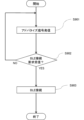
- Fig. 13 is a flowchart showing an example of a process flow related to electrocardiogram measurement performed by the portable electrocardiograph 30.
- the control unit 101 detects the contact state between each electrode and the skin via the contact detection unit 111 and the A/D conversion unit 112 (S1101).
- the control unit 101 (contact state classification unit 113) then classifies the detected contact state into four levels: "good,” “slightly poor contact,” “poor contact,” and “no contact,” and notifies the user of the contact level after classification (S1102).
- the contact state of the left electrode 12a and the first right electrode 12b is indicated by the number of lit LED indicator lights of the left electrode contact level display LED 31a and the right electrode contact level display LED 31b.
- the number of lit indicator lights can be 0 for "no contact,” 1 for "poor contact,” 2 for "slightly poor contact,” and 3 for "good.”
- control unit 101 performs a process to determine whether the contact state of both the first right electrode 12b and the left electrode 12a is "good” (S1103). If it is determined that the contact state of at least either electrode is not "good”, the process proceeds to step S1104, where it determines whether a predetermined time has elapsed in that state (S1104).
- the predetermined time here is set to an appropriate time (e.g., 5 seconds) to wait for the user to bring the electrode contact state into "good” state.
- step S1104 If it is determined in step S1104 that the predetermined time has not elapsed, the control unit 101 returns to step S1011 and repeats the subsequent processes. On the other hand, if it is determined in step S1104 that the predetermined time has elapsed, the control unit 101 proceeds to step S1106.
- control unit 101 determines in step S1103 that the contact state of all electrodes is "good,” it performs processing to determine whether a predetermined time has elapsed in that state (S1105).
- the predetermined time is set to a time (e.g., 3 seconds) appropriate for determining whether the state in which all electrodes are in "good” contact is not temporary but is stable. If the control unit 101 determines in step S1105 that the predetermined time has not elapsed, it returns to step S1101 and repeats the subsequent processing. On the other hand, if it determines in step S1105 that the predetermined time has elapsed, it proceeds to step S1106.
- the control unit 101 When performing electrocardiogram measurement, the control unit 101 indicates that electrocardiogram measurement is in progress by blinking the measurement status notification LED 13 on the front of the main unit at a predetermined rhythm (S1106), and also stores the electrocardiogram signal output from the differential amplifier 94 and acquired via the A/D conversion unit 103 in the memory unit 105 as needed (S1107). Note that the classified electrode contact status level is also stored in the memory unit together with the electrocardiogram signal. The stored information on the electrocardiogram signal and the electrode contact status level is linked to the information on the time when each information was acquired and stored in the memory unit 105.
- step S1108 the control unit 101 executes a process to determine whether or not a predetermined time (e.g., 30 seconds) for electrocardiogram measurement has elapsed (S1108). If it is determined that the predetermined time has not elapsed, the process returns to step S1107 and repeats the subsequent processes. On the other hand, if it is determined in step S1108 that the predetermined measurement time has elapsed, the measurement status notification LED 13 is turned off and notification of the electrode contact level is terminated (S1109), and the series of processes related to electrocardiogram measurement is terminated.
- a predetermined time e.g. 30 seconds
- the portable electrocardiograph 30 can, even when used alone, notify the user of the electrode contact level in stages, execute electrocardiogram measurement processing, and record electrocardiogram waveform data.
- the classified contact level is also saved along with the electrocardiogram waveform data, when the stored electrocardiogram waveform is later checked, for example by displaying it on a display, the contact level of the first right electrode 12b and the left electrode 12a at the time the waveform was detected can be checked together with the electrocardiogram waveform.
- a portable electrocardiograph can be used to display various information using a display means such as a liquid crystal display.
- the electrode contact level can be notified in the display manner shown in the first embodiment and its modified examples.
- the portable electrocardiograph shown in the second embodiment may be provided with a communication unit so as to be capable of communicating with an information processing terminal.
- the electrocardiograph alone can notify the user of the contact level, and by linking with the information processing terminal, the contact level can be notified in a manner with higher usability.
- the communication unit is not limited to one for performing BLE communication, but may be an antenna capable of performing other wireless communication such as Wi-Fi (registered trademark) or infrared communication. It may also be connected to another information processing terminal via a wired connection.
- Wi-Fi registered trademark
- infrared communication may also be connected to another information processing terminal via a wired connection.
- present invention has been applied to a portable electrocardiograph in the above, the present invention can also be applied to non-portable electrocardiographs, and can also be applied to bioinformation measuring devices other than electrocardiographs.
- the information processing terminal is not limited to a smartphone, but may be another mobile information processing terminal such as a tablet terminal, or may be a stationary terminal.
Landscapes
- Health & Medical Sciences (AREA)
- Life Sciences & Earth Sciences (AREA)
- Physics & Mathematics (AREA)
- Engineering & Computer Science (AREA)
- Pathology (AREA)
- General Health & Medical Sciences (AREA)
- Molecular Biology (AREA)
- Chemical & Material Sciences (AREA)
- Public Health (AREA)
- Veterinary Medicine (AREA)
- Animal Behavior & Ethology (AREA)
- Surgery (AREA)
- Medical Informatics (AREA)
- Biomedical Technology (AREA)
- Heart & Thoracic Surgery (AREA)
- Biophysics (AREA)
- Biochemistry (AREA)
- Chemical Kinetics & Catalysis (AREA)
- Immunology (AREA)
- General Physics & Mathematics (AREA)
- Analytical Chemistry (AREA)
- Electrochemistry (AREA)
- Artificial Intelligence (AREA)
- Computer Networks & Wireless Communication (AREA)
- Evolutionary Computation (AREA)
- Fuzzy Systems (AREA)
- Mathematical Physics (AREA)
- Computer Vision & Pattern Recognition (AREA)
- Physiology (AREA)
- Psychiatry (AREA)
- Signal Processing (AREA)
- Measurement And Recording Of Electrical Phenomena And Electrical Characteristics Of The Living Body (AREA)
Priority Applications (3)
| Application Number | Priority Date | Filing Date | Title |
|---|---|---|---|
| DE112023005203.4T DE112023005203T5 (de) | 2023-03-30 | 2023-11-13 | Vorrichtung zur Messung biologischer Informationen und ein System zur Messung biologischer Informationen |
| CN202380093325.6A CN120641045A (zh) | 2023-03-30 | 2023-11-13 | 生物体信息计测装置和生物体信息计测系统 |
| US19/305,319 US20250389686A1 (en) | 2023-03-30 | 2025-08-20 | Biological information measurement device and biological information measurement system |
Applications Claiming Priority (2)
| Application Number | Priority Date | Filing Date | Title |
|---|---|---|---|
| JP2023056661A JP2024143784A (ja) | 2023-03-30 | 2023-03-30 | 生体情報計測装置、及び生体情報計測システム |
| JP2023-056661 | 2023-03-30 |
Related Child Applications (1)
| Application Number | Title | Priority Date | Filing Date |
|---|---|---|---|
| US19/305,319 Continuation US20250389686A1 (en) | 2023-03-30 | 2025-08-20 | Biological information measurement device and biological information measurement system |
Publications (1)
| Publication Number | Publication Date |
|---|---|
| WO2024202193A1 true WO2024202193A1 (ja) | 2024-10-03 |
Family
ID=92903747
Family Applications (1)
| Application Number | Title | Priority Date | Filing Date |
|---|---|---|---|
| PCT/JP2023/040736 Ceased WO2024202193A1 (ja) | 2023-03-30 | 2023-11-13 | 生体情報計測装置、及び生体情報計測システム |
Country Status (5)
| Country | Link |
|---|---|
| US (1) | US20250389686A1 (https=) |
| JP (1) | JP2024143784A (https=) |
| CN (1) | CN120641045A (https=) |
| DE (1) | DE112023005203T5 (https=) |
| WO (1) | WO2024202193A1 (https=) |
Citations (3)
| Publication number | Priority date | Publication date | Assignee | Title |
|---|---|---|---|---|
| JP2009118999A (ja) * | 2007-11-14 | 2009-06-04 | Omron Healthcare Co Ltd | 携帯型心電計および心電波形表示システム |
| JP2018099283A (ja) * | 2016-12-20 | 2018-06-28 | パナソニックIpマネジメント株式会社 | 電子機器、情報処理装置、情報処理方法およびプログラム |
| JP2019013409A (ja) * | 2017-07-06 | 2019-01-31 | オムロンヘルスケア株式会社 | 電気治療器、電気治療器のパッドおよびその製造方法 |
-
2023
- 2023-03-30 JP JP2023056661A patent/JP2024143784A/ja active Pending
- 2023-11-13 CN CN202380093325.6A patent/CN120641045A/zh active Pending
- 2023-11-13 WO PCT/JP2023/040736 patent/WO2024202193A1/ja not_active Ceased
- 2023-11-13 DE DE112023005203.4T patent/DE112023005203T5/de active Pending
-
2025
- 2025-08-20 US US19/305,319 patent/US20250389686A1/en active Pending
Patent Citations (3)
| Publication number | Priority date | Publication date | Assignee | Title |
|---|---|---|---|---|
| JP2009118999A (ja) * | 2007-11-14 | 2009-06-04 | Omron Healthcare Co Ltd | 携帯型心電計および心電波形表示システム |
| JP2018099283A (ja) * | 2016-12-20 | 2018-06-28 | パナソニックIpマネジメント株式会社 | 電子機器、情報処理装置、情報処理方法およびプログラム |
| JP2019013409A (ja) * | 2017-07-06 | 2019-01-31 | オムロンヘルスケア株式会社 | 電気治療器、電気治療器のパッドおよびその製造方法 |
Also Published As
| Publication number | Publication date |
|---|---|
| US20250389686A1 (en) | 2025-12-25 |
| JP2024143784A (ja) | 2024-10-11 |
| CN120641045A (zh) | 2025-09-12 |
| DE112023005203T5 (de) | 2025-10-09 |
Similar Documents
| Publication | Publication Date | Title |
|---|---|---|
| KR20190065102A (ko) | 심전도 측정 장치 | |
| KR102173725B1 (ko) | 생체 신호를 측정하는 방법 및 장치 | |
| KR102518671B1 (ko) | 전자장치 및 그 제어방법 | |
| JP6710636B2 (ja) | 生体信号の局所的収集、生体電気信号に基づく発話補助インターフェース内のカーソル制御、および生体電気信号に基づく覚醒検出 | |
| US20230000418A1 (en) | Portable electrocardiograph, electrocardiograph system, and non-transitory recording medium having program recorded therein | |
| JP7388198B2 (ja) | 生体情報計測装置 | |
| JP7484250B2 (ja) | 携帯型心電装置及び心電測定システム | |
| CN215503016U (zh) | 生物信息电检测装置和可穿戴健康设备 | |
| KR20170143083A (ko) | 휴대용 복합 생체신호 측정장치 | |
| WO2024202193A1 (ja) | 生体情報計測装置、及び生体情報計測システム | |
| CN114650770A (zh) | 心电波形测量装置、信息管理系统、心电波形测量装置的控制方法以及程序 | |
| US20220346654A1 (en) | Portable electrocardiographic device | |
| KR20200000406A (ko) | 심전도 측정 장치 | |
| KR102269411B1 (ko) | 심전도 측정 장치 | |
| CN204679967U (zh) | 一种具有鼠标垫的鼠标系统 | |
| JP7424036B2 (ja) | 携帯型心電波形計測装置、情報管理システム、携帯型心電波形計測装置の制御方法、及び、プログラム | |
| US20250387062A1 (en) | Biological information measuring device | |
| KR20050008972A (ko) | 생체측정계를 구비하는 휴대기기 | |
| US20240081718A1 (en) | Biological information measurement device | |
| CN205107667U (zh) | 基于小波分析远程心电监护与预警系统 | |
| CN114554960B (zh) | 心电测量装置 | |
| JPWO2014002519A1 (ja) | 生体情報記録装置 | |
| TWI466069B (zh) | Ethnic physiological information detection device and cardiovascular disease prevention and treatment of wireless care methods | |
| CN121647692A (zh) | 手机壳及其心电采集方法 | |
| CN116327201A (zh) | 体表信号采集系统及方法 |
Legal Events
| Date | Code | Title | Description |
|---|---|---|---|
| 121 | Ep: the epo has been informed by wipo that ep was designated in this application |
Ref document number: 23930822 Country of ref document: EP Kind code of ref document: A1 |
|
| DPE2 | Request for preliminary examination filed before expiration of 19th month from priority date (pct application filed from 20040101) | ||
| WWE | Wipo information: entry into national phase |
Ref document number: 202517072756 Country of ref document: IN |
|
| WWE | Wipo information: entry into national phase |
Ref document number: 202380093325.6 Country of ref document: CN |
|
| WWE | Wipo information: entry into national phase |
Ref document number: 112023005203 Country of ref document: DE |
|
| WWP | Wipo information: published in national office |
Ref document number: 202517072756 Country of ref document: IN |
|
| WWP | Wipo information: published in national office |
Ref document number: 202380093325.6 Country of ref document: CN |
|
| WWP | Wipo information: published in national office |
Ref document number: 112023005203 Country of ref document: DE |
|
| 122 | Ep: pct application non-entry in european phase |
Ref document number: 23930822 Country of ref document: EP Kind code of ref document: A1 |