WO2024202095A1 - 移載システム - Google Patents
移載システム Download PDFInfo
- Publication number
- WO2024202095A1 WO2024202095A1 PCT/JP2023/028570 JP2023028570W WO2024202095A1 WO 2024202095 A1 WO2024202095 A1 WO 2024202095A1 JP 2023028570 W JP2023028570 W JP 2023028570W WO 2024202095 A1 WO2024202095 A1 WO 2024202095A1
- Authority
- WO
- WIPO (PCT)
- Prior art keywords
- rotation
- hoist
- transfer system
- angle
- force
- Prior art date
- Legal status (The legal status is an assumption and is not a legal conclusion. Google has not performed a legal analysis and makes no representation as to the accuracy of the status listed.)
- Ceased
Links
Images



Classifications
-
- B—PERFORMING OPERATIONS; TRANSPORTING
- B25—HAND TOOLS; PORTABLE POWER-DRIVEN TOOLS; MANIPULATORS
- B25J—MANIPULATORS; CHAMBERS PROVIDED WITH MANIPULATION DEVICES
- B25J13/00—Controls for manipulators
-
- B—PERFORMING OPERATIONS; TRANSPORTING
- B66—HOISTING; LIFTING; HAULING
- B66F—HOISTING, LIFTING, HAULING OR PUSHING, NOT OTHERWISE PROVIDED FOR, e.g. DEVICES WHICH APPLY A LIFTING OR PUSHING FORCE DIRECTLY TO THE SURFACE OF A LOAD
- B66F19/00—Hoisting, lifting, hauling or pushing, not otherwise provided for
Definitions
- the present invention relates to a transfer system. Specifically, the present invention relates to a transfer system that includes a balancer that assists in the lifting of a hoist from which a load is suspended.
- Balancers that support the transportation of cargo (heavy objects) are known.
- the balancer generates a force (lifting support force) that lifts a rod that extends vertically and has a sling that suspends the cargo at its lower end.
- the balancer is equipped with a load sensor that detects the weight of the cargo, and adjusts the lifting support force based on the detection value of the load sensor (see, for example, JP 2018-150173 A).
- the cargo to be transported is stacked on the bucket.
- each cargo may be tilted at a different angle. Therefore, when lifting a new cargo with a hoist, it may be necessary to adjust the angle of the hoist depending on the inclination angle of the cargo.
- the balancer described above did not take into consideration adjusting the angle of the hoist depending on the cargo.
- the present invention was devised in light of these points, and aims to provide a transfer system that can adjust the angle of the hoisting device according to the cargo being handled, and can transport the cargo using the lifting support force generated by the balancer.
- the transfer system of the present invention comprises a hoist from which a cargo is suspended, a balancer that holds the hoist so that it can be displaced and generates an upward support force that raises the hoist, a rotation mechanism that is interposed between the balancer and the hoist and rotatably holds the hoist so that the inclination angle of the hoist can be changed, a robot arm that controls the rotation angle of the rotation mechanism to generate a hoist rotation force that rotates the hoist, and a control unit that generates a hoist rotation force in the robot arm to adjust the rotation angle when the cargo is suspended from the hoist.
- the tilt angle of the swivel mechanism is adjusted (i.e., changed or maintained) by the robot arm according to the tilt angle of the cargo.
- the hoist is lifted together with the swivel mechanism using the lifting support force of the balancer.
- the tilt angle of the hoist is adjusted according to each of the cargo objects having different tilt angles, making it possible to transport these cargo objects.
- the lifting device rotation force generated by the robot arm may be smaller than the force required to adjust the rotation angle when the load is suspended.
- the robot arm of this transfer system can change the inclination angle of the hoist when no load is suspended, but cannot change the inclination angle of the hoist when the load is suspended.
- the load suspended from the hoist can be transported using the lifting support force of the balancer. In other words, even a robot arm that cannot generate a large force (specifically, a rotational force of the hoist) can be applied to this transfer system.
- the center of gravity of the total weight of the swivel mechanism and the lifting device is located near the vertical rotation axis of the lifting device.
- the inclination angle of the hoist will approach a specific angle due to gravity, at least when the load is not suspended from the hoist and the robot arm is not generating a hoist rotation force.
- the robot arm needs to generate a relatively large hoist rotation force to change the hoist tilt angle.
- the hoist tilt angle can be maintained at a small value even if the robot arm does not generate a large hoist rotation force. This allows the robot arm to easily adjust the hoist rotation angle.
- the center of gravity of the total weight may be approximately coincident with the center of rotation of the sling.
- the moment of inertia of the rotation mechanism and the hoisting device is small, so the robot arm can easily adjust the inclination angle of the hoisting device.
- the rotation mechanism and the lifting device may be configured so that the center of gravity of the total weight of the rotation mechanism and the lifting device is located near the rotation center point of the lifting device, so that when the robot arm is not connected to the rotation mechanism and an object is not suspended from the lifting device and the rotation angle is changed, the rotation angle does not return to a specific angle due to gravity.
- the robot arm can change the hoist's rotation angle without generating a large hoist rotation force.
- the robot arm may be configured to be able to adjust the rotation angle when no load is being suspended, due to the center of gravity of the total weight of the swivel mechanism and the hoist being near the vertical rotation axis of the hoist.
- the robot arm can easily adjust the rotation angle of the hoist when the load is suspended from the hoist.
- At least one of the swivel mechanism and the hoist may include a balance weight to move the center of gravity of the total weight closer to the center of rotation.
- a balance weight may be provided on the swivel mechanism and/or the hoist to bring the total weight center of gravity closer to the rotation center of the hoist.
- the position where the balance weight is provided and the weight of the balance weight can be adjusted appropriately depending on the shape of the swivel mechanism and the hoist, and the positional relationship of the hoist to the swivel mechanism, etc.
- the swivel mechanism includes a load sensor that detects a force acting on the hoist in a specific direction determined according to the inclination angle, and the balancer generates a lifting support force according to the force detected by the load sensor.
- control unit may be configured to generate an arm lifting force in the robot arm that lifts the rotation mechanism after the cargo is suspended from the hoist, and to lift the cargo using the combined force of the lifting support force and the arm lifting force.
- the specific direction in the second aspect is, for example, the vertical direction when the swivel mechanism is not tilted.
- the weight of the cargo detected by the load sensor is smaller than the actual value. Therefore, the lifting support force generated by the balancer is smaller than when the specific direction is parallel to the vertical direction. In other words, the lifting support force is insufficient.
- the transfer system according to the present invention includes a robot arm, and the robot arm compensates for the lack of thrust (lifting operation force) required to continue and complete weight assistance in the following manner, making it possible to transport the cargo with less force.
- the lifting support force of the balancer causes the angle of the load sensor (i.e., the specific direction) to approach the vertical direction, and in the process, the weight of the cargo detected by the load sensor gradually approaches the actual value.
- the specific direction becomes parallel to the vertical direction, and the weight of the cargo detected by the load sensor becomes equal to the actual value.
- the rotation mechanism includes a Z rotating body rotatably connected to the balancer around a vertical rotation axis, an X rotating body rotatably connected to the Z rotating body around a horizontal first rotation axis, and a Y rotating body rotatably connected to the X rotating body around a horizontal second rotation axis and connected to the lifting device.
- the intersections of the vertical rotation axis, the first horizontal rotation axis, and the second horizontal rotation axis become the rotation center of the swivel mechanism. Therefore, according to the third aspect, a universal joint can be formed in which the swivel mechanism is rotatably connected to the end of the balancer.
- the Z joint that rotatably holds the Z rotating body relative to the balancer may be located above the first horizontal rotation axis and the second horizontal rotation axis.
- the Z rotating body is a balancer rod whose upper end is connected to a balancer and extends vertically, and the X rotating body and the Y rotating body are connected to the lower end of the balancer rod.
- the Z joint is a rotary joint that rotatably holds the balancer rod, and the first horizontal rotation axis and the second horizontal rotation axis are located below this rotary joint.
- the X rotating body and the Y rotating body are located below the Z joint. This makes it possible to avoid a complex structure for the rotation mechanism.
- the hoist is configured so that when the robot arm is not generating a rotational force on the hoist and an object is suspended from the hoist, the center of gravity of the suspended object is located vertically below the center of rotation of the hoist.
- the inclination angle of the hoisting tool is reduced by the force of gravity acting on the load suspended from the hoisting tool. This reduces the force required for the robot arm to rotate the load together with the hoisting tool around the vertical axis of rotation.
- the sling may include a holding portion having a through hole through which the end of the cargo is inserted.
- the inclination angle of the sling is adjusted according to the inclination angle of the end of the load. Then, when the sling rises, the center of gravity of the load is vertically below the rotation center point of the sling, so the inclination angle of the sling and the load changes significantly, reducing the possibility of the load falling off the sling.
- the cargo may be a crankshaft, which is a part of an internal combustion engine.
- the crankshaft of an internal combustion engine i.e., the cargo
- the crankshaft of an internal combustion engine has a complex shape, so when multiple crankshafts are loaded, there is a high possibility that the inclination angles will differ from one another.
- the inclination angle of the hoist is adjusted according to the inclination angle of the crankshaft, and one end of the crankshaft is inserted into the through hole of the hoist. Therefore, according to this aspect, it is possible to transport the crankshafts one by one.
- FIG. 1 is a schematic diagram of a transfer system according to an embodiment.
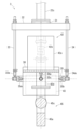
- 1 is a side view showing a rotation mechanism connected to a balancer and a robot arm, and a workpiece suspended by a hoist of the rotation mechanism.
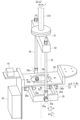
- FIG. FIG. 2 is a perspective view of a rotation mechanism from which the robot arm and the operation box are omitted.
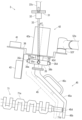
- FIG. FIG. 2 is a schematic diagram of a robot arm.
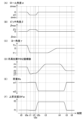
- 6 is a time chart showing the height of the hoisting device, the rotation angle of the swivel mechanism, the detection value of the load sensor, and the lifting support force of the balancer, which change under the control of the control device.
- 13 is a diagram showing how a workpiece is hung from a hoist of a rotated swivel mechanism.
- FIG. 1 is a side view showing a rotation mechanism connected to a balancer and a robot arm, and a workpiece suspended by a hoist of the rotation mechanism.
- FIG. FIG. 2 is a perspective view
- Figure 1 shows a transfer system 1 according to an embodiment.
- the transfer system 1 lifts a work 71 (the cargo to be transported, which in this embodiment is a crankshaft of a multi-cylinder engine) from a portable bucket 81, and then places it on a belt conveyor 82.
- the transfer system 1 includes a balancer 2, a turning mechanism 3, a robot 5, and control devices 61, 62.
- the balancer 2 is a loading device (weight auxiliary device, transport auxiliary device) that generates a force to lift the workpiece 71 vertically upward.
- the balancer 2 includes a base 21, a first rod 22a to a third rod 22c, a parallel rod 23, a joint 24, and a piston 25.
- the base 21 is installed on the upper end of a support 91 that extends upward from the floor surface.
- One end of the first rod 22a is supported (held) rotatably (pivotally) relative to the base 21. That is, the first rod 22a is connected to the base 21 via a rotary joint.
- the rotation axis of this rotary joint extends horizontally and is perpendicular to the axis of the first rod 22a. Therefore, when the first rod 22a rotates, the vertical position of the other end of the first rod 22a changes.
- the parallel rod 23 has one end rotatably supported relative to the base 21 and extends parallel to the first rod 22a.
- a parallel link (parallelogram link) is formed by the first rod 22a and the parallel rod 23, as well as the base 21 and the joint 24 that rotatably support the first rod 22a and the parallel rod 23. Therefore, even if the vertical position of the joint 24 changes with the rotation of the first rod 22a, the inclination angle of the joint 24 does not change.
- One end of the second rod 22b is supported rotatably relative to the joint 24. That is, the second rod 22b is connected to the joint 24 via a rotary joint (whose tilt angle does not change).
- the rotation axis of this rotary joint extends in the up-down direction (vertical direction) and is perpendicular to the axis of the second rod 22b. Therefore, even if the second rod 22b rotates relative to the joint 24, the up-down position of the other end of the second rod 22b does not change.
- One end (upper end) of the third rod 22c is rotatably supported relative to the other end of the second rod 22b. Specifically, one end of the third rod 22c is inserted into a bearing 22b1 (see FIG. 1) provided on the second rod 22b and is rotatably held by the bearing 22b1. That is, the third rod 22c is connected to the second rod 22b via a rotary joint (also called a "yaw joint” or “Z joint”). The rotation axis of this rotary joint extends in the vertical direction and coincides with the axis of the third rod 22c. That is, the third rod 22c extends in the vertical direction.
- the other end (lower end) of the third rod 22c is fastened to the rotating mechanism 3.
- the rotation angle of the third rod 22c is also called (written as) the "rotation angle" or yaw angle ⁇ .
- the rotating mechanism 3 rotates around the axis of the third rod 22c as the yaw angle ⁇ changes.
- the base 21 incorporates an air cylinder to which compressed air is supplied from a compressor (both not shown).
- the piston 25 expands and contracts according to the pressure of the compressed air supplied to the air cylinder, and as a result, the rotation angle of the first rod 22a is controlled.
- the vertical positions of the second rod 22b and the third rod 22c (and thus the swivel mechanism 3) change according to the rotation angle of the first rod 22a.
- the force that the balancer 2 generates by extending and retracting the piston 25 to lift the third rod 22c is also called the lifting support force Fw.
- the balancer 2 executes "auto-balance control" that causes the lifting support force Fw to follow the load Ws detected by the load sensor 42e described below.
- the balancer 2 does not generate a force that moves the third rod 22c horizontally and does not hinder the horizontal movement of the third rod 22c.
- the swivel mechanism 3 includes a fastening portion 31, a horizontal frame 32, a pair of vertical frames 33, 34, a rotating frame 35, a base 36, a balance weight 41, an operation box 42, a camera 43, and a hoist 45.
- the hoist 45 included in the swivel mechanism 3 is held displaceably by the third rod 22c of the balancer 2 (i.e., the end of the balancer 2).
- the third rod 22c may be treated as part of the swivel mechanism 3.
- the fastening portion 31 has a roughly disk shape and is fastened to the lower end of the third rod 22c of the balancer 2.
- the central portion of the upper surface of the horizontal frame 32 is joined to the lower surface of the fastening portion 31.
- the horizontal frame 32 has a roughly rectangular parallelepiped shape and extends in the horizontal direction.
- the vertical frames 33, 34 are fastened near the upper ends to the portions near one and the other ends of the horizontal frame 32.
- the vertical frames 33, 34 have a roughly cylindrical shape and extend in the up-down direction.
- Bearing portions 33a, 34a having through holes (bearings) are fastened to the lower ends of the vertical frames 33, 34, respectively.
- the rotating frame 35 is a frame material having a rectangular shape and a rectangular cross section.
- a pair of rotating shafts 35a, 35b and a pair of rotating shafts 35c, 35d extend perpendicularly (to the outer peripheral surface of the rotating frame 35) from the outer surface of the rotating frame 35.
- Each of the rotating shafts 35a to 35d has a protruding portion that is approximately cylindrical.
- the rotating shafts 35a, 35b and the bearings 33a, 34a each constitute a rotating joint (also called a "roll joint"). That is, the protruding portions of the rotating shafts 35a, 35b are inserted into the through holes of the bearings 33a, 34a, so that the rotating frame 35 is supported rotatably relative to the vertical frames 33, 34.
- the rotation angle of the rotating frame 35 relative to the vertical frames 33, 34 is also called the roll angle ⁇ .
- the rotating shafts 35c, 35d each form a rotating joint (also called a "pitch joint") together with a pair of bearings 36a, 36b extending downward from the underside of the base 36.
- a through hole is provided at the lower end of each of the bearings 36a, 36b, and the protruding portions of the rotating shafts 35c, 35d are inserted into these through holes.
- the base 36 is supported rotatably relative to the rotating frame 35.
- the rotation angle of the base 36 relative to the rotating frame 35 is also called the pitch angle ⁇ .
- the attitude of the swivel mechanism 3 relative to the third rod 22c (also called the "tilt angle”) changes with the change in the roll angle ⁇ and/or the pitch angle ⁇ .
- the rotation axes of the yaw joint, pitch joint, and roll joint are mutually perpendicular at the center of rotation Gc (see Figure 3).
- the base 36 of the rotation mechanism 3 is connected to the third rod 22c by a universal joint that rotates about the center of rotation Gc. Therefore, the combination of the roll angle ⁇ , pitch angle ⁇ , and yaw angle ⁇ ( ⁇ , ⁇ , ⁇ ) represents the rotation angle of the rotation mechanism 3 (specifically, the base 36) in a relative coordinate system with the center of rotation Gc as the origin.
- the vertical frames 33, 34 rotatably connected together with the third rod 22c to the second rod 22b around the Z axis are also referred to as the "Z rotating body” for convenience.
- the rotating frame 35 rotatably connected to the vertical frames 33, 34 around the rotation axis of the roll joint (first horizontal rotation axis) is also referred to as the "X rotating body” for convenience.
- the base 36 rotatably connected to the rotating frame 35 around the rotation axis of the pitch joint (second horizontal rotation axis) is also referred to as the "Y rotating body” for convenience.
- the roll angle ⁇ and pitch angle ⁇ each become 0° when the vertical direction relative to the main body 42a of the operation box 42 described below is parallel to the extension direction of the vertical frames 33, 34.
- the vertical direction relative to the main body 42a is also called the "specific direction.”
- the specific direction is parallel to the vertical direction.
- the specific direction is a direction determined according to the tilt angle.
- the yaw angle ⁇ becomes 0° when the workpiece 71 suspended from the hoist 45 is placed on the belt conveyor 82.
- the roll angle ⁇ increases when rotating in the direction indicated by the arrow A1 in FIG. 3.
- the pitch angle ⁇ increases when rotating in the direction indicated by the arrow A2.
- the yaw angle ⁇ increases when rotating in the direction indicated by the arrow A3.
- a balance weight 41, an operation box 42, a camera 43, and a hoist 45 are fastened to the base 36.
- the center of gravity of the rotation mechanism 3 (more specifically, the rotation frame 35 and the base 36 including the balance weight 41, the operation box 42, the camera 43, and the hoist 45) coincides with the center of rotation Gc.
- the operation box 42 is an operation terminal for the balancer 2, and includes a main body 42a, a display 42b, an operation unit 42c, a cylindrical portion 42d, and a load sensor 42e.
- the bottom surface of the main body 42a is fastened to the base 36.
- the display 42b is a liquid crystal display device, and displays the operating status of the balancer 2 (see FIG. 1).
- the operation unit 42c includes multiple push buttons, and is operated by the operator to change the operating status of the balancer 2. In this embodiment, the operator operates the operation unit 42c to start auto-balance control by the balancer 2 prior to the transport of the workpiece 71 by the transfer system 1.
- the cylindrical portion 42d has an approximately cylindrical shape and extends downward (i.e., in a specific direction) from the bottom surface of the main body portion 42a through a through hole 36c (see FIG. 3) formed in the base 36.
- the load sensor 42e is a well-known one-axis force sensor built into the main body portion 42a (see FIG. 4).
- the load sensor 42e detects a load Ws acting on the cylindrical portion 42d in a specific direction and transmits a signal representing the load Ws to the control unit (not shown) of the balancer 2.
- the control unit of the balancer 2 controls the lifting support force Fw based on the load Ws when performing auto-balance control.
- a hoist 45 used to hoist the workpiece 71 is fastened to the lower end of the cylindrical portion 42d.
- a swivel mechanism 3 is interposed between the balancer 2 and the hoist 45.
- the center of rotation Gc is also the center of rotation of the hoist 45.
- the rotation angles ( ⁇ , ⁇ , ⁇ ) of the above-mentioned rotating mechanism 3 are also the rotation angles of the hoist 45.
- the workpiece 71 includes a main body portion 71a and a tip portion 71b (see FIG. 2).
- the main body portion 71a has a plurality of crank pins to which connecting rods corresponding to each cylinder of the engine are connected.
- the tip portion 71b has a generally cylindrical shape and extends coaxially from the main body portion 71a.
- the hoist 45 includes a main shaft portion 45a, a holding portion 45b, and a handle portion 45c (see FIG. 2).
- One end of the main shaft portion 45a is fixed (fastened) to the cylindrical portion 42d of the operation box 42.
- the holding portion 45b is connected to the other end of the main shaft portion 45a.
- the holding portion 45b is a plate-shaped member, and has a through hole 45d formed therein through which the tip portion 71b of the workpiece 71 is inserted.
- the handle 45c is a rod-shaped member that is held by the worker, and the gripping portion of the handle 45c extends parallel to the main shaft 45a.
- the handle 45c may be omitted.
- Camera 43 is a well-known stereo camera device incorporating a pair of optical cameras (not shown). Camera 43 captures a pair of forward images in response to instructions (requests) from control device 61. Camera 43 then acquires point cloud data representing the three-dimensional shape of the area contained in the forward image based on the distance (i.e., baseline length) between the forward image and the optical cameras. Furthermore, camera 43 transmits an electronic file in PLY (Polygon File Format) format representing the point cloud data to control device 61.
- PLY Polygon File Format
- the control device 61 is a general-purpose microcomputer equipped with a CPU, RAM, and non-volatile memory, and is connected to the camera 43 and the control device 62 so that data can be communicated therewith.
- the CPU reads data, performs numerical calculations, and outputs the results of calculations by sequentially executing specified programs (routines).
- the RAM temporarily stores data referenced by the CPU.
- the non-volatile memory is composed of ROM and rewritable flash memory, etc., and stores the programs (applications) executed by the CPU and data files referenced when the programs are executed.
- the robot 5 is a multi-joint robot arm (manipulator) including a base 51 and a first arm 52a to a sixth arm 52f.
- the base 51 is installed at the upper end of a support 92 that extends upward from the floor surface (see FIG. 1).
- the base 51 and the first arm 52a to the sixth arm 52f are each connected to each other by six rotational joints.
- the robot 5 is a six-axis (six degrees of freedom) robot arm.
- the circular surface 53 (see FIG. 5) at the tip of the sixth arm 52f is fastened to the pedestal 36 (see FIG. 2).
- the combination of the rotation angles (joint displacements) of the rotary joints of the robot 5 is also referred to as the arm displacement angles Ra ( ⁇ 1, ⁇ 2, ⁇ 3, ⁇ 4, ⁇ 5, ⁇ 6).
- the robot 5 has built-in electric motors (not shown) corresponding to each of the six rotary joints, and the rotation amount of each of the electric motors (i.e., the arm displacement angles Ra) is controlled by the control device 62.
- the position and orientation (i.e., the tilt angle and rotation angle) of the tip of the sixth arm 52f i.e., the circular surface 53
- the position and orientation (i.e., the tilt angle and rotation angle) of the tip of the sixth arm 52f can be obtained (calculated) by a well-known robot forward kinematics method based on the shapes (including the lengths) and arm displacement angles Ra of each of the first arm 52a to the sixth arm 52f.
- the control device 62 controls the robot 5 to transport the workpieces 71 loaded in the transport bucket 81 one by one onto the belt conveyor 82.
- the control device 62 is a general-purpose microcomputer having a similar structure to the control device 61. That is, the control device 62 includes a CPU, RAM, and non-volatile memory, and the non-volatile memory stores a control program for the robot 5 that is executed by the CPU.
- an absolute coordinate system (absolute coordinate values) is used.
- the origin O of the absolute coordinate system is the intersection of the upper end surface of the base 51 and the rotation axis of the rotation joint of the base 51 and the first arm 52a (see FIG. 1).
- the X-axis, Y-axis, and Z-axis of the absolute coordinate system are mutually perpendicular and form a left-handed system.
- the Z-axis is vertically upward.
- the X-axis is the direction of movement of the workpiece 71 transported by the belt conveyor 82.
- the control device 62 controls the position and attitude (angle) of the hoist 45, represented as the hoist position P (x, y, z, xr, yr, zr), in order to transport the workpiece 71.
- the hoist position P is a combination of the hoist coordinate value Pp (x, y, z) and the hoist angle value Pr (xr, yr, zr).
- the hoist coordinate value Pp is the absolute coordinate value of the center of the through hole 45d and the center position in the thickness direction of the holding portion 45b (tool center point Pt in this embodiment, see Figure 2).
- the hoist angle value Pr is a combination of the rotation amounts for each of the X-axis, Y-axis, and Z-axis, and corresponds to the extension direction of the axis of the workpiece 71 (specifically, the tip portion 71b) suspended by the hoist 45.
- control device 62 calculates the target value of the arm displacement angle Ra corresponding to the target value of the position and orientation of the tool center point Pt, and controls the electric motors for the first arm 52a to the sixth arm 52f based on the target value of the arm displacement angle Ra.
- the lifting tool position P is controlled by the control device 62.
- the control device 62 controls the hoist position P so that the axis of the workpiece 71 (specifically, the tip 71b) on the belt conveyor 82 extends in the Y-axis direction, and then places the workpiece 71 on the belt conveyor 82.
- the hoist position P when the workpiece 71 is placed on the belt conveyor 82 i.e., when the bottom surface of the workpiece 71 contacts the belt conveyor 82
- the hoist coordinate value Pp of the placement position P5 is (xb, yb, zb).
- the roll angle ⁇ , pitch angle ⁇ , and yaw angle ⁇ are each approximately 0° (i.e., ⁇ 0, ⁇ 0°, and ⁇ 0°).
- the reason why the roll angle ⁇ and pitch angle ⁇ are approximately 0° i.e., the specific direction is approximately parallel to the vertical direction) will be explained.
- the center of gravity of the turning mechanism 3 not including the workpiece 71 coincides with the rotation center Gc.
- the center of gravity Gw of the workpiece 71 suspended by the hoist 45 is located directly below the third rod 22c (see FIG. 2).
- the control device 62 sends a request to the control device 61 to obtain the position and axis extension direction of the next workpiece 71 to be transported.
- the control device 61 causes the camera 43 to transmit a PLY file and obtains the position and angle of the next workpiece 71 to be transported based on the PLY file received from the camera 43. More specifically, the control device 61 extracts the shape of the workpiece 71 included in the PLY file using template data that reflects the three-dimensional shape of the workpiece 71. That is, the control device 61 extracts each of the workpieces 71 included in the PLY file by well-known pattern matching processing.
- control device 61 selects one of the workpieces 71 that is located higher than the other workpieces 71 and that is unlikely to cause the remaining workpieces 71 to move when that workpiece 71 is lifted (i.e., there is a low risk that the stacked assembly of workpieces 71 will collapse). Furthermore, the control device 61 obtains the position of the tip 71b of the selected workpiece 71 and the extension direction of the axis, and transmits this as a response to the control device 62.
- the control device 62 When the control device 62 receives a response from the control device 61, it acquires the insertion start position P1 and insertion completion position P2, which are the hoisting tool position P for the workpiece 71 to be transported next.
- the hoisting tool position P When the hoisting tool position P is at the insertion start position P1, the through hole 45d of the hoisting tool 45 reaches the tip 71b, and the surface of the holding part 45b of the hoisting tool 45 on the spindle part 45a side (i.e., the surface on the left side of the holding part 45b in FIG. 2) is perpendicular to the axis of the tip 71b.
- the tip 71b is fully inserted into the through hole 45d. Therefore, if the hoisting tool position P is at the insertion completion position P2, there is an extremely low possibility that the workpiece 71 will fall off the hoisting tool 45 even if the hoisting tool 45 subsequently rises.
- the hoisting tool position P moves from the insertion start position P1 to the insertion completion position P2, the tool center point Pt moves on the axis of the tip 71b.
- the control device 62 moves the hoist position P through the insertion start position P1 to the insertion completion position P2, and then raises the hoist 45. That is, the hoist 45 is used to hoist the workpiece 71.
- the control device 62 then moves the workpiece 71 above the belt conveyor 82, and then lowers the hoist 45 to place the workpiece 71 on the belt conveyor 82. Note that the belt conveyor 82 is stopped when the workpiece 71 is placed.
- the robot 5 is able to move the hoist position P from the insertion start position P1 to the insertion completion position P2.
- each of the workpieces 71 moved sequentially by the transfer system 1 is loaded onto the portable bucket 81, and so there is a high possibility that they are tilted at different angles. Therefore, when inserting the tip 71b through the through hole 45d, it is necessary to adjust the roll angle ⁇ and pitch angle ⁇ according to the inclination of the workpiece 71.
- the robot 5 needs to generate a force that rotates (swings) the swivel mechanism 3 including the hoist 45 (also referred to as the "hoist rotation force").
- the center of gravity of the rotation mechanism 3 coincides with the center of rotation Gc, so the moment of inertia of the rotation mechanism 3 is relatively small. Therefore, the robot 5 can rotate the rotation mechanism 3 with a relatively weak force.
- the center of gravity of the rotation mechanism 3 is located below the center of rotation Gc, the moment of inertia of the rotation mechanism 3 increases and the roll angle ⁇ and pitch angle ⁇ tend to return to 0° due to gravity acting on the hoist 45. This increases the force required to rotate the rotation mechanism 3. In other words, a stronger robot arm is required for the robot 5.
- the base 36 is fixed to the operation box 42 together with the camera 43 and the hoist 45, and the operation box 42 is connected to the lower end of the third rod 22c via a universal joint, the center of gravity of the rotation mechanism 3 will be located below the center of rotation Gc (located above the operation box 42).
- the center of gravity of the turning mechanism 3 coincides with the center of rotation Gc, so even though the force that the robot 5 can generate is relatively small, the robot 5 can rotate the turning mechanism 3.
- the robot 5 can control the lifting tool position P according to the insertion start position P1 and insertion completion position P2 obtained based on the inclination.
- the robot 5 can change the roll angle ⁇ and pitch angle ⁇ based on the inclination of the workpiece 71.
- each of the workpieces 71 loaded on the portable bucket 81 can be lifted by the lifting device 45.
- the swivel mechanism 3 can change (rotate, pivot) the roll angle ⁇ in the range of angle ⁇ min to angle ⁇ max (where ⁇ min ⁇ -15° and 15° ⁇ max).
- the swivel mechanism 3 can change the pitch angle ⁇ in the range of angle ⁇ min to angle ⁇ max (where ⁇ min ⁇ -15° and 15° ⁇ max).
- the total weight of the swivel mechanism 3, including the hoist 45 and the operation box 42, is approximately 13 kg, and the weight of the workpiece 71 is approximately 26 kg.
- the load capacity of the robot 5 is 12.5 kg. Therefore, the swivel mechanism 3 and the workpiece 71 cannot be transported by the force generated by the robot 5 alone. Therefore, in the transfer system 1, the control device 62 controls the robot 5 to control the position of the swivel mechanism 3 (and therefore the position of the workpiece 71) while the balancer 2 is generating an upward support force Fw corresponding to the load Ws.
- the robot 5 When the robot 5 moves the swivel mechanism 3 in the vertical direction, it generates a force of approximately 40 N upward or downward, regardless of whether the workpiece 71 is suspended by the hoist 45 or not.
- the force generated by the robot 5 to raise the swivel mechanism 3 is also called the "arm raising force.”
- control device 62 transports the workpieces 71 loaded on the portable bucket 81 one by one onto the belt conveyor 82. Specifically, the control device 62 controls the robot 5 so that the hoist position P repeatedly moves in the order of search position Ps ⁇ insertion start position P1 ⁇ insertion completion position P2 ⁇ rise completion position P3 ⁇ descent start position P4 ⁇ placement position P5 ⁇ insertion release position P6 ⁇ search position Ps. Note that the search position Ps, rise completion position P3, descent start position P4, and insertion release position P6 will be described in order.
- the control device 62 acquires the insertion start position P1 and the insertion completion position P2. More specifically, the control device 62 requests the control device 61 to transmit the position and angle (direction of extension of the axis) of the workpiece 71 to be transported next. In response, the control device 61 controls the camera 43 to transmit the PLY file. In addition, the control device 61 selects the next workpiece 71 to be transported based on the PLY file received from the camera 43. Furthermore, the control device 61 acquires the position and orientation of the tip 71b of the selected workpiece 71 and transmits it as a response to the control device 62. The control device 62 acquires the insertion start position P1 and the insertion completion position P2 based on the response received from the control device 61.
- the search position Ps is pre-adapted so that the workpiece 71 loaded in the portable bucket 81 is included in the shooting range of the camera 43 (i.e., the area included in the forward image).
- the Z coordinate value of the search position Ps is the coordinate value zs.
- the search position Ps is a fixed value, but the control device 62 may change the search position Ps depending on the position of the portable bucket 81 and the state of the workpiece 71 loaded in the portable bucket 81, etc.
- the control device 62 sends an information acquisition request to the control device 61 at time t0, and then acquires (calculates) the insertion start position P1 and the insertion completion position P2 based on the response received from the control device 61.
- the control device 62 moves the sling position P through the insertion start position P1 to the insertion completion position P2.
- the sling position P starts moving to the insertion start position P1 at time t0a, and reaches the insertion start position P1 at time t1. Furthermore, the sling position P reaches the insertion completion position P2 at time t2.
- the roll angle ⁇ and pitch angle ⁇ for the search position Ps are 0° and the yaw angle ⁇ is angle ⁇ s (where ⁇ s>0).
- the roll angle ⁇ , pitch angle ⁇ and yaw angle ⁇ for the insertion start position P1 and the insertion completion position P2 are angles ⁇ 1, ⁇ 1 and ⁇ 1, respectively (where ⁇ 1 ⁇ 0, ⁇ 1>0 and ⁇ 1 ⁇ 0).
- the Z coordinate values for the insertion start position P1 and the insertion completion position P2 are coordinate value z1 and coordinate value z2, respectively (where z1 ⁇ z2).
- the tip 71b of the workpiece 71 being transported is inclined so that the base portion (i.e., the boundary portion with the main body portion 71a) is higher than the tip portion (i.e., the portion opposite the main body portion 71a). Therefore, when the control device 62 moves the hoist position P to the insertion start position P1, it rotates the turning mechanism 3 so that the roll angle ⁇ becomes a negative value (specifically, angle ⁇ 1). In addition, when the control device 62 inserts the tip 71b into the through hole 45d of the hoist 45 (i.e., when the hoist position P is moved from the insertion start position P1 to the insertion completion position P2), it maintains the roll angle ⁇ at angle ⁇ 1.
- the hoist 45 and work 71 are shown by solid lines when the hoist position P is at the insertion start position P1.
- the hoist 45 is shown by a two-dot chain line when the hoist position P is at the insertion completion position P2.
- Figure 7 shows the swivel mechanism 3 and work 71 as viewed from a direction parallel to the rotation axis of the roll joint.
- the pitch angle ⁇ and yaw angle ⁇ are also controlled by the control device 62. That is, the control device 62 controls the lifting tool position P (i.e., controls the robot 5) based on the insertion start position P1 and insertion completion position P2 obtained according to the posture (tilt) of the workpiece 71 being transported, and as a result, the pitch angle ⁇ and yaw angle ⁇ of the rotation mechanism 3 are also controlled.
- the lifting completion position P3 is a hoisting position P that is above the insertion completion position P2.
- the workpiece 71 suspended by the hoisting device 45 is lifted up at time t2b. Accordingly, the roll angle ⁇ and pitch angle ⁇ become 0°.
- the workpiece 71 loaded on the portable bucket 81 is suspended by the hoisting device 45 at time t2b, and as a result, the axis of the workpiece 71 extends horizontally (as shown in FIG. 2).
- the specific direction i.e., the direction in which the load sensor 42e detects the load Ws
- the load Ws detected by the load sensor 42e is smaller than the actual total weight of the hoist 45, workpiece 71, etc.
- the lifting support force Fw generated by the balancer 2 is smaller than when the roll angle ⁇ and pitch angle ⁇ are both 0°.
- the specific direction is parallel to the vertical upward direction (i.e., the roll angle ⁇ and pitch angle ⁇ are both 0°), so the load Ws is a load w1 that corresponds to the total weight of the cylindrical portion 42d, which is located below the load sensor 42e, and the hoist 45. Therefore, the balancer 2 generates a force f1 of a magnitude equal to the weight of the swivel mechanism 3 including the hoist 45 as an ascent support force Fw.
- the magnitude of the load Ws is slightly smaller than the load w2 corresponding to the total weight of the cylindrical portion 42d, the hoist 45, and the workpiece 71. Therefore, the lifting support force Fw is slightly smaller than the force f2 equal to the total weight of the swivel mechanism 3 and the workpiece 71.
- the robot 5 cannot generate the force required to rotate the turning mechanism 3 including the workpiece 71 (i.e., the force required to control the roll angle ⁇ and/or the pitch angle ⁇ ).
- the control device 62 can control the roll angle ⁇ and/or the pitch angle ⁇ via the robot 5 only when the workpiece 71 is not suspended by the hoist 45.
- control device 62 moves the hoisting device position P through the ascent completion position P3 to the descent start position P4.
- the hoisting device position P reaches the ascent completion position P3 at time t3, and reaches the descent start position P4 at time t4.
- the descent start position P4 is the hoist position P that is above the placement position P5.
- the Z coordinate values of the ascent completion position P3 and the descent start position P4 are both Z coordinate value zu (fixed value).
- the Z coordinate value zu is pre-adjusted so that the hoist 45 and the workpiece 71 do not collide with the portable bucket 81 and the pillars 91, 92, etc., when they move.
- the yaw angle ⁇ approaches 0°. That is, the posture of the workpiece 71 suspended by the hoist 45 (specifically, the axial direction of the workpiece 71 projected onto the XY plane) approaches the placement position P5.
- the magnitude of the load Ws detected by the load sensor 42e begins to decrease.
- the control device 62 moves the hoist position P through the placement position P5 to the insertion release position P6.
- the hoist position P reaches the placement position P5 at time t5, and reaches the insertion release position P6 at time t6.
- the hoist position P moves from the placement position P5 to the insertion release position P6, the state in which the tip 71b of the workpiece 71 placed on the belt conveyor 82 is inserted through the through hole 45d of the hoist 45 is eliminated.
- the hoist 45 moves upward after the hoist position P reaches the insertion release position P6, the hoist 45 does not come into contact (collide) with the workpiece 71 on the belt conveyor 82.
- the control device 62 maintains the roll angle ⁇ at 0° until the hoist 45 separates from the workpiece 71.
- the control device 62 moves the hoisting tool position P to the search position Ps via a path adapted to prevent the hoisting tool 45 from colliding with the portable bucket 81 and the pillars 91, 92, etc.
- FIG. 6 the illustration of the period during which the hoisting tool position P moves from the insertion release position P6 to the search position Ps is omitted.
- the belt conveyor 82 is operated and the workpiece 71 on the belt conveyor 82 moves a predetermined distance (length).
- the rotation angle (i.e., roll angle ⁇ , pitch angle ⁇ , and yaw angle ⁇ ) of the swivel mechanism 3 is controlled according to the position and posture (rotation angle including the tilt angle) of the work 71 (i.e., the cargo).
- the robot 5 controlled by the control device 62 only needs to generate a force strong enough to control the rotation angle of the swivel mechanism 3 including the hoist 45 that is not suspending the work 71.
- the robot 5 does not need to control the tilt angle of the swivel mechanism 3 including the hoist 45 that is suspending the work 71. Therefore, the hoist rotation force that the robot 5 can generate (specifically, the force that adjusts the tilt angle of the swivel mechanism 3) is smaller than the force required to change the tilt angle of the swivel mechanism 3 including the hoist 45 that is suspending the work 71.
- the robot 5 can control the roll angle ⁇ and pitch angle ⁇ when the workpiece 71 is suspended by a relatively weak force. That is, the robot 5 can adjust the rotation angle of the turning mechanism 3 when the workpiece 71 is not suspended by the hoist 45. Therefore, the control device 62 can control the robot 5 to rotate the turning mechanism 3 according to the insertion start position P1 and move the hoist position P from the insertion start position P1 to the insertion completion position P2 while maintaining the rotation angle of the turning mechanism 3.
- the rotation center Gc is close to the center of gravity of the turning mechanism 3, when the robot 5 is not connected to the turning mechanism 3 and the workpiece 71 is not suspended from the hoist 45, if an operator touches the turning mechanism 3 to change the rotation angle, the rotation angle of the turning mechanism 3 does not change even if the operator releases his/her hands from the turning mechanism 3. If the rotation center Gc is away from the center of gravity of the turning mechanism 3, when the operator releases his/her hands from the turning mechanism 3, the turning mechanism 3 rotates so that the center of gravity of the turning mechanism 3 is vertically below the rotation center Gc. In other words, when the operator releases his/her hands from the turning mechanism 3, the rotation angle of the turning mechanism 3 returns to a specific angle.
- the balancer 2 since the balancer 2 generates an upward support force Fw based on the load Ws in a specific direction detected by the load sensor 42e, the upward support force Fw may be insufficient depending on the angle between the specific direction and the vertical direction. However, the insufficiency of the upward support force Fw is compensated for by the arm upward force generated by the robot 5. In other words, the balancer 2 does not need to be equipped with a three-axis force sensor that can detect the load of the hoist 45, workpiece 71, etc., regardless of the rotation angle of the swivel mechanism 3.
- the swivel mechanism 3 including the X, Y and Z rotors makes it possible to rotatably connect the swivel mechanism 3 including the hoist 45 to the end of the balancer 2 (i.e., the lower end of the third rod 22c) with the center of rotation Gc located below the operation box 42 (specifically, the main body 42a). Therefore, the main body 42a is located above the center of rotation Gc and the hoist 45 is located below the center of rotation Gc, and the center of gravity of the swivel mechanism 3 can be aligned with the center of rotation Gc by the relatively light balance weight 41. In other words, the structure of the swivel mechanism 3 in which the center of rotation Gc is located below the main body 42a contributes to reducing the moment of inertia of the swivel mechanism 3.
- the work 71 (cargo) is suspended by inserting the tip 71b (i.e., the cylindrical portion) of the work 71 through the through hole 45d formed in the hoist 45.
- the cargo may be suspended by inserting the cylindrical portion of the hoist through a through hole formed in the cargo.
- the cargo may be suspended by the lower end of the hoist adsorbing to the cargo.
- the shape of the hoist may be adapted so that the center of gravity of the suspended cargo is vertically below (including close to) the center of rotation Gc.
- the work 71 (i.e., the load) was the crankshaft of an internal combustion engine.
- a load other than a crankshaft may be transported by the transfer system 1.
- the load transported by the transfer system 1 may be, for example, a cylinder block or cylinder head, which is a part of an internal combustion engine and has a complex shape.
- the load may be a heavy object other than an internal combustion engine part (e.g., a mold).
- the rotation angle of the hoist i.e., the tilt angle and the swivel angle of the swivel mechanism 3
- the tilt angle of the hoist i.e., the tilt angle and the swivel angle of the swivel mechanism 3
- the center of gravity of the load may be separated from the geometric center point of the shape of the load, and even in this case, the shape of the hoist can be adapted so that the center of gravity of the suspended load is located vertically below (including near the vertically below) the center of rotation of the hoist.
- the position of the center of gravity of the swivel mechanism 3 including the hoist 45 coincided with the center of rotation Gc.
- the position of the center of gravity of the swivel mechanism 3 may be spaced apart from the center of rotation Gc within a range in which the roll angle ⁇ and pitch angle ⁇ of the swivel mechanism 3 including the hoist 45 without the workpiece 71 suspended therefrom can be controlled by the robot 5.
- the position of the center of gravity of the swivel mechanism 3 including the hoist 45 without the workpiece 71 suspended therefrom may be located near the axis of the third rod 22c (i.e., the vertical rotation axis).
- the position of the center of gravity of the swivel mechanism 3 including the hoist 45 without the workpiece 71 suspended therefrom may be located vertically below (including near the vertically below) the center of rotation Gc when the workpiece 71 is not suspended from the hoist 45 and the roll angle ⁇ and pitch angle ⁇ are both 0°.
- the yaw joint of the swivel mechanism 3 (i.e., the Z joint, more specifically, the bearing 22b1) was located above the pitch joint and roll joint (i.e., the rotating frame 35).
- the swivel mechanism that rotatably holds the sling 45 may be configured using a ball joint.
- the ball joint that rotatably holds the sling 45 is configured, for example, by a spherical portion disposed at the lower end of the balancer rod that extends downward from the tip of the second rod 22b, and a recess that protrudes upward from the top surface of the operation box 42, covers the spherical portion of the balancer rod, and holds the spherical portion.
- the yaw joint, pitch joint, and roll joint are each in the same position as each other.
- the balance weight 41 was fastened to the base 36.
- the balance weight may be fixed to the hoist 45.
- the fixed position and weight of the balance weight can be adapted so that the center of gravity of the swivel mechanism 3 including the hoist 45 approaches the center of rotation Gc.
- the balance weight 41 may be omitted as long as the center of gravity of the swivel mechanism 3 including the hoist 45 is near the center of rotation Gc.
- the camera 43 was fixed to the swivel mechanism 3. Alternatively, the camera 43 may be fixed to the floor surface.
- each of the control devices 61 and 62 may be performed by a single control device (control unit).
- one or both of the control devices 61 and 62 may be configured by a dedicated controller rather than a general-purpose microcomputer.
- the balancer 2 performs auto-balance control to make the upward support force Fw follow the load Ws detected by the load sensor 42e.
- the balancer 2 may generate an upward support force Fw of a magnitude determined without relying on the detection value of the load sensor 42e. For example, when the workpiece 71 is suspended from the hoist 45 (in the period from time t2a to time t5 in FIG. 6), the control device 62 may control the balancer 2 so that the magnitude of the upward support force Fw becomes force f2. Similarly, when the workpiece 71 is not suspended from the hoist 45, the control device 62 may control the balancer 2 so that the magnitude of the upward support force Fw becomes force f1.
Landscapes
- Engineering & Computer Science (AREA)
- Mechanical Engineering (AREA)
- Life Sciences & Earth Sciences (AREA)
- Geology (AREA)
- Structural Engineering (AREA)
- Robotics (AREA)
- Manipulator (AREA)
Abstract
本願に係る移載システムは、荷役物が吊り下げられた吊具を上昇させる力を発生させるバランサを利用し、且つ吊り下げられる荷役物の傾斜角度に応じて吊具の角度を調整することができる。この移載システムは、バランサと吊具との間に介装され、吊具の傾斜角度が変更可能となるように吊具を回転可能に保持する旋回機構と、旋回機構の回転角度を制御して吊具を回転させる吊具回転力を発生させるロボットアームと、吊具に荷役物が吊り下げられる際にロボットアームに吊具回転力を発生させて回転角度を調整する制御部と、を有している。
Description
本発明は、移載システムに関する。具体的には、荷役物が吊り下げられた吊具の上昇を支援するバランサを含む移載システムに関する。
荷役物(重量物)の運搬を支援するバランサ(荷役装置)が知られている。バランサは、例えば、荷役物を吊り下げる吊具が下端に接続され且つ上下方向に延在するロッドを上昇させる力(上昇支援力)を発生させる。加えて、バランサは、荷役物の重量を検出する荷重センサを備え、荷重センサの検出値に基づいて上昇支援力を調整する(例えば、特開2018-150173号公報を参照)。
ところで、運搬される荷役物がバケット上に積み重ねられている場合がある。この場合、荷役物のそれぞれが異なる角度で傾斜している可能性がある。そのため、吊具により荷役物を新たに吊り上げる際、荷役物の傾斜角度に応じて吊具の角度を調整する必要があり得る。しかしながら、上述したバランサにおいては荷役物に応じて吊具の角度を調整することは考慮されていなかった。
本発明は、このような点に鑑みて創案されたものであり、荷役物に応じて吊具の角度を調整することが可能であり且つバランサが発生させる上昇支援力を用いて荷役物を運搬することができる移載システムを提供することを目的とする。
上記課題を解決するため、本発明に係る移載システムは、荷役物が吊り下げられる吊具と、吊具を変位可能に保持し且つ吊具を上昇させる上昇支援力を発生させるバランサと、バランサと吊具との間に介装され、吊具の傾斜角度が変更可能となるように吊具を回転可能に保持する旋回機構と、旋回機構の回転角度を制御して吊具を回転させる吊具回転力を発生させるロボットアームと、吊具に荷役物が吊り下げられる際にロボットアームに吊具回転力を発生させて回転角度を調整する制御部と、を有する。
本移載システムによれば、吊具が荷役物に吊り下げられる際、荷役物の傾斜角度に応じて旋回機構の傾斜角度がロボットアームによって調整(即ち、変更又は維持)される。吊具が荷役物に吊り下げられると、バランサの上昇支援力を用いて吊具が旋回機構と共に持ち上げられる。従って、傾斜角度が互いに異なる荷役物のそれぞれに応じて吊具の傾斜角度が調整され、以て、これらの荷役物を運搬することが可能となる。
本移載システムにおいて、ロボットアームが発生させられる吊具回転力は、荷役物が吊り下げられている状態において回転角度を調整するのに必要な力よりも小さくても良い。
この場合、本移載システムに係るロボットアームは、荷役物が吊り下げられていない状態において吊具の傾斜角度を変更できるが、荷役物が吊り下げられている状態においては吊具の傾斜角度を変更できない。一方、荷役物が吊り下げられている状態においてはバランサの上昇支援力を用いて吊具に吊り下げられた荷役物を運搬することができる。即ち、大きな力(具体的には、吊具回転力)を発生させることができないロボットアームであっても本移載システムに適用できる。
本移載システムの一態様(第1態様)において、旋回機構及び吊具の総重量の重心は、吊具の垂直回転軸の近傍にある。
仮に、旋回機構及び吊具の総重量の重心(総重量重心)から吊具の垂直回転軸までの距離が比較的大きければ、少なくとも荷役物が吊具に吊り下げられておらず且つロボットアームが吊具回転力を発生させていない状態において、吊具の傾斜角度が重力によって特定の角度に近づくこととなる。換言すれば、この場合、吊具の傾斜角度を変更するためにはロボットアームが比較的大きな吊具回転力を発生させる必要がある。一方、第1態様によれば、ロボットアームが大きな吊具回転力を発生させなくても吊具の傾斜角度が小さい状態に維持され得る。そのため、ロボットアームは吊具の旋回角度を容易に調整することが可能となる。
第1態様において、総重量の重心は、吊具の回転中心点と略一致していても良い。
この場合、旋回機構及び吊具の慣性モーメントが小さくなるので、ロボットアームは、吊具の傾斜角度を容易に調整することができる。
更に、本移載システムにおいて、旋回機構及び吊具は、旋回機構及び吊具の総重量の重心が吊具の回転中心点の近傍に位置しており、そのためにロボットアームが旋回機構に連結されておらず且つ吊具に荷役物が吊り下げられていない状態において回転角度が変更された場合には回転角度が重力によって特定の角度に戻らない、ように構成されても良い。
上述したように、総重量重心から吊具の回転中心点までの距離が比較的大きいと、吊具の回転角度が重力によって特定の回転角度に近づこうとする。一方、総重量重心から吊具の回転中心点までの距離が充分に小さければ、例えば、作業者によって吊具の回転角度が変更されたとき、吊具は特定の回転角度に戻らない。旋回機構及び吊具がこのように構成されている場合、ロボットアームは大きな吊具回転力を発生させなくても吊具の回転角度を変更することが可能となる。
更に、本移載システムにおいて、ロボットアームは、旋回機構及び吊具の総重量の重心が吊具の垂直回転軸の近傍にあることに起因して、荷役物が吊り下げられていない状態において回転角度を調整することができるように構成されても良い。
この場合、ロボットアームは、吊具に荷役物が吊り下げられる際に吊具の回転角度を容易に調整することが可能となる。
上記第1態様において、旋回機構及び吊具の少なくとも一方は、総重量の重心を回転中心点に近づけるためのバランスウェイトを含んでいても良い。
即ち、総重量重心を吊具の回転中心点に近づけるため、旋回機構及び/又は吊具にバランスウェイトが配設されていても良い。バランスウェイトが配設される位置及びバランスウェイトの重量は、旋回機構及び吊具の形状及び旋回機構に対する吊具の位置関係等に応じて適宜調整され得る。
本移載システムの他の態様(第2態様)において、旋回機構は、吊具に作用する、傾斜角度に応じて定まる特定方向の力を検出する荷重センサを含み、バランサは、荷重センサが検出した力に応じて上昇支援力を発生させる。
第2態様において、制御部は、荷役物が吊具に吊り下げられた後、ロボットアームに旋回機構を上昇させるアーム上昇力を発生させ、上昇支援力及びアーム上昇力の合力により荷役物を上昇させる、ように構成されても良い。
第2態様における特定方向は、例えば、旋回機構が傾斜していないときの鉛直方向である。この場合、旋回機構が傾斜しているとき(即ち、特定方向が鉛直方向に対して平行でないとき)、荷重センサによって検出される荷役物の重量は実際の値と比較して小さくなる。そのため、バランサが発生させる上昇支援力は、特定方向が鉛直方向に対して平行である場合と比較して小さくなる。即ち、上昇支援力が不足する。しかし、本発明に係る移載システムはロボットアームを含んでおり、ロボットアームが以下の要領で重量補助が継続、完結されるのに必要な推力(上昇操作力)の不足を補うことによって、より少ない力で荷役物の運搬が可能となる。即ち、バランサの上昇支援力により荷重センサの角度(即ち、特定方向)が鉛直方向に近づいていき、その過程で荷重センサによって検出される荷役物の重量が徐々に実際の値に近づいていく。最終的には特定方向が鉛直方向に対して平行となり荷重センサによって検出される荷役物の重量は実際の値と等しくなる。
本移載システムの他の態様(第3態様)において、旋回機構は、バランサに対して垂直回転軸周りに回転可能に連結されるZ回転体と、Z回転体に水平第1回転軸周りに回転可能に連結されるX回転体と、X回転体に水平第2回転軸周りに回転可能に連結され且つ吊具に対して連結されるY回転体と、を含む。
第3態様では、垂直回転軸、水平第1回転軸及び水平第2回転軸のそれぞれの交点が旋回機構の回転中心となる。従って、第3態様によれば、旋回機構がバランサの端部に対して回転可能に連結される自在継手を構成することができる。
第3態様において、Z回転体をバランサに対して回転可能に保持するZ関節は、水平第1回転軸及び水平第2回転軸よりも上方にあっても良い。
例えば、Z回転体は、上端がバランサに連結され且つ垂直に延びるバランサロッドであり、X回転体及びY回転体は、バランサロッドの下端に対して連結される。この場合、Z関節は、バランサロッドを回転可能に保持する回転関節であり、水平第1回転軸及び水平第2回転軸は、この回転関節よりも下方に位置する。即ち、X回転体及びY回転体がZ関節よりも下方に位置する。そのため、旋回機構の構造が複雑になることが回避され得る。
本移載システムの他の態様(第4態様)において、吊具は、ロボットアームが吊具回転力を発生させておらず且つ吊具に荷役物が吊り下げられているとき、吊り下げられた荷役物の重心が吊具の回転中心点の鉛直下方に位置するように構成される。
第4態様によれば、吊具に吊り下げられた荷役物に作用する重力によって吊具の傾斜角度が小さくなる。そのため、ロボットアームが荷役物を吊具と共に垂直回転軸周りに旋回させるために必要な力を低減することができる。
第4態様において、吊具は、荷役物の端部が挿入される貫通孔が形成された保持部を含んでいても良い。
この場合、吊具に荷役物が吊り下げられるとき、荷役物の端部の傾斜角度に応じて吊具の傾斜角度が調整される。次いで、吊具が上昇するとき、荷役物の重心が吊具の回転中心点の鉛直下方にあるので、吊具及び荷役物の傾斜角度が大きく変化して吊具から荷役物が脱落する可能性が低くなる。
更に、第4態様において、荷役物は、内燃機関の部品であるクランクシャフトであっても良い。
一般に、内燃機関のクランクシャフト(即ち、荷役物)は複雑な形状を有しているため、複数のクランクシャフトが積載された場合に傾斜角度が互いに異なる可能性が高い。第4態様では、クランクシャフトが吊具に吊り下げられとき、クランクシャフトの傾斜角度に応じて吊具の傾斜角度が調整され且つ吊具の貫通孔にクランクシャフトの一端が挿入される。従って、この態様によれば、クランクシャフトを1つずつ運搬することが可能となる。
本発明の実施形態を図1~7を参照しながら説明する。説明中の同じ符号(参照番号)は、重複する説明をしないが同じ機能を有する同じ要素を意味する。図1に実施形態に係る移載システム1が示される。移載システム1は、ワーク71(運搬される荷役物であり、本実施形態において、多気筒エンジンのクランクシャフト)を可搬バケット81から吊り上げ、次いで、ベルトコンベア82上に載置する。移載システム1は、バランサ2、旋回機構3、ロボット5及び制御装置61、62を含んでいる。
バランサ2は、ワーク71を鉛直上方に持ち上げる力を発生させる荷役装置(重量補助装置、運搬補助装置)である。バランサ2は、基部21、第1ロッド22a~第3ロッド22c、並行ロッド23、関節部24及びピストン25を含んでいる。
基部21は、床面から上方へ延在する支柱91の上端部に設置されている。第1ロッド22aの一端は、基部21に対して回転可能(回動可能)に支持(保持)されている。即ち、第1ロッド22aは、回転関節を介して基部21に接続されている。この回転関節の回転軸は、水平方向に延在し且つ第1ロッド22aの軸線と直交している。従って、第1ロッド22aが回転すると、第1ロッド22aの他端の上下位置が変化する。並行ロッド23は、一端が基部21に対して回転可能に支持され且つ第1ロッド22aに並行して延在している。
第1ロッド22aの他端及び並行ロッド23の他端は、関節部24によって回転可能に支持されている。第1ロッド22a及び並行ロッド23、並びに、第1ロッド22aと並行ロッド23とを回転可能に支持する基部21及び関節部24によって平行リンク(平行四辺形リンク)が構成されている。そのため、第1ロッド22aの回転に伴って関節部24の上下位置が変化しても、関節部24の傾斜角度は変化しない。
第2ロッド22bの一端は、関節部24に対して回転可能に支持されている。即ち、第2ロッド22bは、回転関節を介して(傾斜角度が変化しない)関節部24に接続されている。この回転関節の回転軸は、上下方向(鉛直方向)に延在し且つ第2ロッド22bの軸線と直交している。従って、第2ロッド22bが関節部24に対して回転しても、第2ロッド22bの他端の上下位置は変化しない。
第3ロッド22cの一端(上端)は、第2ロッド22bの他端に対して回転可能に支持されている。具体的には、第3ロッド22cの一端は、第2ロッド22bに設けられた軸受22b1(図1を参照)に挿入され且つ軸受22b1によって回転可能に保持されている。即ち、第3ロッド22cは、回転関節(「ヨー関節」又は「Z関節」とも称呼される)を介して第2ロッド22bに接続されている。この回転関節の回転軸は、上下方向に延在し且つ第3ロッド22cの軸線と一致している。即ち、第3ロッド22cは、上下方向に延在している。
第3ロッド22cの他端(下端)には、旋回機構3が締結されている。第3ロッド22cの回転角度は、「旋回角度」又はヨー角度γとも称呼(表記)される。換言すれば、ヨー角度γの変化に伴って旋回機構3が第3ロッド22cの軸線を中心に回転する。
基部21は、圧縮機から圧縮空気が供給されるエアシリンダを内蔵している(何れも不図示)。エアシリンダに供給される圧縮空気の圧力に応じてピストン25が伸縮し、その結果として第1ロッド22aの回転角度が制御される。第1ロッド22aの回転角度に応じて第2ロッド22b及び第3ロッド22c(ひいては、旋回機構3)の上下位置が変化する。
ピストン25が伸縮することによってバランサ2が発生させる第3ロッド22cを上昇させる力は、上昇支援力Fwとも称呼される。バランサ2は、後述される荷重センサ42eによって検出された荷重Wsに上昇支援力Fwを追随させる「オートバランス制御」を実行する。その反面、バランサ2は、第3ロッド22cを水平方向に移動させる力は発生させず且つ第3ロッド22cの水平方向における移動を妨げない。
図1~4に示されるように、旋回機構3は、締結部31、横枠32、一対の縦枠33、34、回転枠35、台座36、バランスウェイト41、操作ボックス42、カメラ43及び吊具45を含んでいる。換言すれば、旋回機構3に含まれる吊具45は、バランサ2の第3ロッド22c(即ち、バランサ2の端部)によって変位可能に保持されている。なお、第3ロッド22cは、旋回機構3の一部として扱われても良い。
締結部31は、略円盤形状を有し、バランサ2の第3ロッド22cの下端に締結されている。締結部31の下面には、横枠32の上面中央部が接合されている。横枠32は、略直方体形状を有し、水平方向に延在している。横枠32の一端及び他端の近傍部には、縦枠33、34の上端近傍部が締結されている。縦枠33、34は、略円柱形状を有し、上下方向に延在している。縦枠33、34の下端には、貫通孔(軸受け)を有する軸受部33a、34aがそれぞれ締結されている。
回転枠35は、四角形形状を有し且つ四角形断面を有する枠材である。回転枠35の外側面からは、一対の回転軸35a、35b及び一対の回転軸35c、35dが(回転枠35の外周面に対して)垂直に延出している。回転軸35a~回転軸35dのそれぞれは、略円筒形状の突出部を有している。
回転軸35a、35b及び軸受部33a、34aは、回転関節(「ロール関節」とも称呼される)をそれぞれ構成している。即ち、回転軸35a、35bの突出部が軸受部33a、34aの貫通孔に挿通されることによって、回転枠35が縦枠33、34に対して回転可能に支持されている。回転枠35の縦枠33、34に対する回転角度は、ロール角度αとも称呼される。
一方、回転軸35c、35dは、台座36の下面から下方へ延出した一対の軸受部36a、36bと共に回転関節(「ピッチ関節」とも称呼される)をそれぞれ構成している。具体的には、軸受部36a、36bのそれぞれの下端には貫通孔が設けられており、且つこれらの貫通孔に回転軸35c、35dのそれぞれの突出部が挿通されている。即ち、台座36は、回転枠35に対して回転可能に支持されている。台座36の回転枠35に対する回転角度は、ピッチ角度βとも称呼される。ロール角度α及び/又はピッチ角度βの変化に伴って旋回機構3の第3ロッド22cに対する姿勢(「傾斜角度」とも称呼される)が変化する。
ヨー関節、ピッチ関節及びロール関節のそれぞれの回転軸は、回転中心Gcにて互いに直交している(図3を参照)。換言すれば、旋回機構3の台座36は、回転中心Gcに対して回転する自在継手(ユニバーサルジョイント)によって第3ロッド22cに連結されている。従って、ロール角度α、ピッチ角度β及びヨー角度γの組合せ(α,β,γ)は、回転中心Gcを原点とする相対座標系における旋回機構3(具体的には、台座36)の回転角度を表している。
第2ロッド22bに対してZ軸(垂直回転軸、即ち、ヨー関節の回転軸)周りに第3ロッド22cと共に回転可能に連結された縦枠33、34は、便宜上、「Z回転体」とも称呼される。縦枠33、34に対してロール関節の回転軸(水平第1回転軸)周りに回転可能に連結された回転枠35は、便宜上、「X回転体」とも称呼される。回転枠35に対してピッチ関節の回転軸(水平第2回転軸)周りに回転可能に連結された台座36は、便宜上、「Y回転体」とも称呼される。
ロール角度α及びピッチ角度βのそれぞれは、後述される操作ボックス42の本体部42aに対する上下方向が、縦枠33、34の延在方向に対して平行であるときに0°となる。本体部42aに対する上下方向は、「特定方向」とも称呼される。ロール角度α及びピッチ角度βが0°であるとき、特定方向は、鉛直方向に対して平行となる。換言すれば、特定方向は、傾斜角度に応じて定まる方向である。一方、ヨー角度γは、吊具45に吊り下げられたワーク71がベルトコンベア82上に載置されるときに0°となる。
ロール角度αは、図3の矢印A1によって示される方向に回転したときに増加する。ピッチ角度βは、矢印A2によって示される方向に回転したときに増加する。ヨー角度γは、矢印A3によって示される方向に回転したときに増加する。
台座36には、バランスウェイト41、操作ボックス42、カメラ43及び吊具45が締結されている。バランスウェイト41の重さ及び台座36における位置が調整された結果として、旋回機構3(より具体的には、回転枠35、及び、バランスウェイト41、操作ボックス42、カメラ43及び吊具45を含む台座36)の重心は、回転中心Gcに一致している。
操作ボックス42は、バランサ2の操作端末であり、本体部42a、ディスプレイ42b、操作部42c、円柱部42d及び荷重センサ42eを含んでいる。本体部42aの下面が台座36に締結されている。ディスプレイ42bは、液晶ディスプレイ装置であり、バランサ2の作動状況が表示される(図1を参照)。操作部42cは、複数の押しボタンを含んでおり、バランサ2の作動状況を変更するために作業者によって操作される。本実施形態において、作業者は、移載システム1によるワーク71の運搬に先立ち、操作部42cを操作してバランサ2によるオートバランス制御を開始させる。
円柱部42dは、略円柱形状を有し、本体部42aの下面から、台座36に形成された貫通孔36c(図3を参照)を貫通して下方(即ち、特定方向)に延在している。荷重センサ42eは、本体部42aに内蔵された周知の1軸力覚センサである(図4を参照)。荷重センサ42eは、円柱部42dに対して特定方向に作用する荷重Wsを検出し、荷重Wsを表す信号をバランサ2の制御部(不図示)へ送信する。バランサ2の制御部は、オートバランス制御の実行時、荷重Wsに基づいて上昇支援力Fwを制御する。円柱部42dの下端には、ワーク71を吊り上げるために用いられる吊具45が締結されている。即ち、バランサ2と吊具45との間に旋回機構3が介装されている。換言すれば、回転中心Gcは、吊具45の回転中心でもある。加えて、上述した旋回機構3の回転角度(α,β,γ)は、吊具45の回転角度でもある。
本実施形態におけるワーク71は、本体部71a及び先端部71bを含んでいる(図2を参照)。本体部71aには、エンジンの各気筒に対応するコンロッドが連結される複数のクランクピンが形成されている。先端部71bは、略円柱形状を有し、本体部71aから同軸状に延在している。
一方、吊具45は、主軸部45a、保持部45b及びハンドル部45cを含んでいる(図2を参照)。主軸部45aの一端が操作ボックス42の円柱部42dに固定(締結)されている。主軸部45aの他端には、保持部45bが連結されている。保持部45bは、板状部材であり、ワーク71の先端部71bが挿通される貫通孔45dが形成されている。
先端部71bが貫通孔45dに挿通された状態にて吊具45が上昇すると、ワーク71も上昇する。即ち、ワーク71が吊具45によって吊り下げられた状態となる。ハンドル部45cは作業者によって把持される棒状部材であり、ハンドル部45cの把持部が主軸部45aに並行して延在している。なお、ハンドル部45cは、省略されても良い。
カメラ43は、一対の光学カメラ(不図示)を内蔵した周知のステレオカメラ装置である。カメラ43は、制御装置61からの指示(要求)に応じて一対の前方画像を撮影する。次いで、カメラ43は、前方画像及び光学カメラ間の距離(即ち、基線長)に基づいて、前方画像に含まれる領域の立体形状を表す点群データを取得する。更に、カメラ43は、点群データを表すPLY(Polygon File Format)形式の電子ファイルを制御装置61へ送信する。
制御装置61は、CPU、RAM及び不揮発性メモリを備えた汎用マイクロコンピュータであり、カメラ43及び制御装置62とデータ通信可能に接続されている。CPUは、所定のプログラム(ルーチン)を逐次実行することによってデータの読み込み、数値演算、及び演算結果の出力等を行う。RAMは、CPUによって参照されるデータを一時的に記憶する。不揮発性メモリは、ROM、及びデータの書き換え可能なフラッシュメモリ等により構成され、CPUが実行するプログラム(アプリケーション)及びプログラムの実行時に参照されるデータファイル等を記憶している。
図5に示されるように、ロボット5は、基部51及び第1アーム52a~第6アーム52fを含む多関節ロボットアーム(マニプレータ)である。基部51は、床面から上方へ延在する支柱92の上端部に設置されている(図1を参照)。基部51及び第1アーム52a~第6アーム52fのそれぞれは、6つの回転関節によって互いに連結されている。即ち、ロボット5は、6軸(6自由度)ロボットアームである。第6アーム52fの先端にある円形面53(図5を参照)は、台座36に締結されている(図2を参照)。
ロボット5が備える回転関節のそれぞれの回転角度(関節変位)の組合せは、アーム変位角度Ra(θ1,θ2,θ3,θ4,θ5,θ6)とも称呼される。ロボット5は6つの回転関節のそれぞれに対応する電動機(不図示)を内蔵しており、電動機のそれぞれの回転量(即ち、アーム変位角度Ra)は制御装置62によって制御される。第6アーム52fの先端部(即ち、円形面53)の位置及び姿勢(即ち、傾斜角度及び旋回角度)は、第1アーム52a~第6アーム52fのそれぞれの(長さを含む)形状及びアーム変位角度Raに基づく周知のロボット順運動学の手法により取得(算出)することができる。
(制御装置によるロボットアームの制御)
制御装置62(制御部)は、ロボット5を制御して、可搬バケット81に積載されたワーク71を1つずつベルトコンベア82上に運搬する。制御装置62は、制御装置61と同様の構造を有する汎用マイクロコンピュータである。即ち、制御装置62はCPU、RAM及び不揮発性メモリを備え、不揮発性メモリはCPUが実行するロボット5の制御プログラムを記憶している。
制御装置62(制御部)は、ロボット5を制御して、可搬バケット81に積載されたワーク71を1つずつベルトコンベア82上に運搬する。制御装置62は、制御装置61と同様の構造を有する汎用マイクロコンピュータである。即ち、制御装置62はCPU、RAM及び不揮発性メモリを備え、不揮発性メモリはCPUが実行するロボット5の制御プログラムを記憶している。
以下の説明において、絶対座標系(絶対座標値)が用いられる。絶対座標系の原点Oは、基部51の上端面と、基部51及び第1アーム52aの回転関節の回転軸と、の交点である(図1を参照)。絶対座標系のX軸、Y軸及びZ軸は、互いに直交し且つ左手系を構成する。Z軸は、鉛直上方である。X軸は、ベルトコンベア82によって運搬されるワーク71の移動方向である。
制御装置62は、ワーク71を運搬するため、吊具位置P(x,y,z,xr,yr,zr)として表される吊具45の位置及び姿勢(角度)を制御する。吊具位置Pは、吊具座標値Pp(x,y,z)と吊具角度値Pr(xr,yr,zr)との組合せである。吊具座標値Ppは、貫通孔45dの中心であり且つ保持部45bの厚さ方向の中心の位置(本実施形態におけるツールセンターポイントPt、図2を参照)の絶対座標値である。吊具角度値Prは、X軸、Y軸及びZ軸のそれぞれに対する回転量の組合せであり、吊具45によって吊り下げられたワーク71(具体的には、先端部71b)の軸線の延在方向に対応している。
即ち、制御装置62は、ツールセンターポイントPtの位置及び姿勢の目標値に対応するアーム変位角度Raの目標値を算出し、且つアーム変位角度Raの目標値に基づいて第1アーム52a~第6アーム52fに係る電動機を制御する。その結果、制御装置62によって吊具位置Pが制御される。
制御装置62は、ベルトコンベア82上のワーク71(具体的には、先端部71b)の軸線がY軸方向に延在するように吊具位置Pを制御した後、ワーク71をベルトコンベア82に載置する。ワーク71がベルトコンベア82に載置されるとき(即ち、ワーク71の下面がベルトコンベア82接触するとき)の吊具位置Pは、載置位置P5とも称呼される。載置位置P5の吊具座標値Ppは(xb,yb,zb)である。
このとき、ロール角度α、ピッチ角度β及びヨー角度γのそれぞれは略0°となる(即ち、α≒0、β≒0°且つγ≒0°)。ロール角度α及びピッチ角度βが略0°となる(即ち、特定方向が鉛直方向に対して略平行となる)理由について説明する。上述したようにワーク71を含まない旋回機構3の重心は回転中心Gcに一致している。加えて、吊具45に吊り下げられたワーク71の重心Gwは、第3ロッド22cの直下に位置している(図2を参照)。そのため、吊具45によってワーク71が吊り下げられているとき、旋回機構3及びワーク71の総重量の重心は、第3ロッド22cの直下にあり、その結果、ロール角度α及びピッチ角度βが略0°となる。
制御装置62は、次に運搬するワーク71の位置及び軸線の延在方向を取得するように要求(リクエスト)を制御装置61へ送信する。この場合、制御装置61は、カメラ43にPLYファイルを送信させ且つカメラ43から受信したPLYファイルに基づいて次に運搬するワーク71の位置及び角度を取得する。より具体的に述べると、制御装置61は、ワーク71の立体形状が反映されたテンプレートデータを用いてPLYファイルに含まれるワーク71の形状を抽出する。即ち、制御装置61は、周知のパターンマッチング処理によってPLYファイルに含まれるワーク71のそれぞれを抽出する。
次いで、制御装置61は、他のワーク71よりも高い位置にあり且つそのワーク71を吊り上げたことによって残りのワーク71が移動してしまう可能性(即ち、積載されて形成されたワーク71の集合体が崩れてしまう危険性)が低いワーク71の1つを選択する。更に、制御装置61は、選択されたワーク71に係る先端部71bの位置及び軸線の延在方向を取得して制御装置62へ応答(レスポンス)として送信する。
制御装置62は、制御装置61から応答を受信すると、次に運搬するワーク71に係る吊具位置Pである挿通開始位置P1及び挿通完了位置P2を取得する。吊具位置Pが挿通開始位置P1にあるとき、吊具45の貫通孔45dが先端部71bに到達し且つ吊具45の保持部45bにおける主軸部45a側の表面(即ち、図2における保持部45bの左側の表面)が先端部71bの軸線と直交している。
吊具位置Pが挿通完了位置P2にあるとき、貫通孔45dに先端部71bが充分に挿し込まれている。そのため、吊具位置Pが挿通完了位置P2にあれば、その後、吊具45が上昇しても、ワーク71が吊具45から脱落する可能性は非常に低い。吊具位置Pが挿通開始位置P1から挿通完了位置P2まで移動すると、ツールセンターポイントPtが先端部71bの軸線上を移動する。
制御装置62は、吊具位置Pを、挿通開始位置P1を経て挿通完了位置P2に移動させた後、吊具45を上昇させる。即ち、吊具45を用いてワーク71を吊り上げる。その後、制御装置62は、ワーク71をベルトコンベア82の上方に移動させてから、吊具45を下降させてワーク71をベルトコンベア82に載置する。なお、ベルトコンベア82は、ワーク71が載置されるときには停止している。
ここで、ロボット5によって吊具位置Pを挿通開始位置P1から挿通完了位置P2まで移動させることが可能である理由について説明する。上述したように、移載システム1によって順次移動させられるワーク71のそれぞれは可搬バケット81に積載されているので、互いに異なる角度にて傾斜している可能性が高い。そのため、貫通孔45dに先端部71bを挿通させるとき、ワーク71の傾斜に応じてロール角度α及びピッチ角度βを調整する必要がある。即ち、吊具45を含む旋回機構3を回転(揺動)させる力(「吊具回転力」とも称呼される)をロボット5が発生させる必要がある。
上述したように、本実施形態においては旋回機構3の重心位置が回転中心Gcと一致しているので、旋回機構3の慣性モーメントが比較的小さくなっている。そのため、ロボット5は、旋回機構3を比較的弱い力によって回転させることができる。
仮に、旋回機構3の重心位置が回転中心Gcよりも下方にあると、旋回機構3の慣性モーメントが増加し且つ吊具45に作用する重力によってロール角度α及びピッチ角度βが0°に戻ろうとする。そのため、旋回機構3を回転させるために必要となる力が大きくなる。即ち、ロボット5として、より強力なロボットアームが必要となる。例えば、操作ボックス42に対して台座36がカメラ43及び吊具45等と共に固定され且つ第3ロッド22cの下端に自在継手を介して操作ボックス42が接続されると、旋回機構3の重心位置が(操作ボックス42の上方にある)回転中心Gcよりも下方となる。
要約すれば、移載システム1においては旋回機構3の重心位置が回転中心Gcと一致しているので、ロボット5が発生可能な力が比較的小さいにも拘らず、ロボット5は旋回機構3を回転させることができる。その結果、運搬される前のワーク71が傾斜していても、ロボット5は、その傾斜に基づいて取得された挿通開始位置P1及び挿通完了位置P2に応じて吊具位置Pを制御することができる。換言すれば、ロボット5は、ワーク71の傾斜に基づいてロール角度α及びピッチ角度βを変更することができる。
本実施形態においてはロール角度α及びピッチ角度βのそれぞれを-15°から15°までの範囲で調整することによって、可搬バケット81に積載されたワーク71のそれぞれを吊具45によって吊り上げることができる。旋回機構3は、ロール角度αを角度αminから角度αmaxまでの範囲で変化(回転、回動)させることができる(ただし、αmin<-15°且つ15°<αmax)。同様に、旋回機構3は、ピッチ角度βを角度βminから角度βmaxまでの範囲で変化させることができる(ただし、βmin<-15°且つ15°<βmax)。
吊具45及び操作ボックス42等を含む旋回機構3の合計重量は約13kgであり、ワーク71の重量は約26kgである。一方、ロボット5の可搬重量は12.5kgである。従って、ロボット5が発生させる力のみによっては旋回機構3及びワーク71を運搬することができない。そのため、移載システム1においては荷重Wsに対応する上昇支援力Fwをバランサ2が発生させている状態にて制御装置62がロボット5を制御して旋回機構3の位置(ひいては、ワーク71の位置)を制御する。なお、ロボット5は、旋回機構3を上下方向に移動させるとき、吊具45によってワーク71が吊り下げられているか否かに依らず、約40Nの力を上方又は下方へ発生させる。ロボット5が発生させる、旋回機構3を上昇させる力は、「アーム上昇力」とも称呼される。
(制御装置の具体的作動)
制御装置61、62の具体的作動について図6のタイムチャートを参照しながら説明する。上述したように、制御装置62は、可搬バケット81に積載されたワーク71をベルトコンベア82上へ1つずつ運搬する。具体的には、制御装置62は、吊具位置Pが、探索位置Ps→挿通開始位置P1→挿通完了位置P2→上昇完了位置P3→下降開始位置P4→載置位置P5→挿通解放位置P6→探索位置Psの順に繰り返し移動するようにロボット5を制御する。なお、探索位置Ps、上昇完了位置P3、下降開始位置P4及び挿通解放位置P6については順を追って説明される。
制御装置61、62の具体的作動について図6のタイムチャートを参照しながら説明する。上述したように、制御装置62は、可搬バケット81に積載されたワーク71をベルトコンベア82上へ1つずつ運搬する。具体的には、制御装置62は、吊具位置Pが、探索位置Ps→挿通開始位置P1→挿通完了位置P2→上昇完了位置P3→下降開始位置P4→載置位置P5→挿通解放位置P6→探索位置Psの順に繰り返し移動するようにロボット5を制御する。なお、探索位置Ps、上昇完了位置P3、下降開始位置P4及び挿通解放位置P6については順を追って説明される。
吊具位置Pが探索位置Psにあるとき、制御装置62は、挿通開始位置P1及び挿通完了位置P2を取得する。より具体的に述べると、制御装置62は、制御装置61に対して次に運搬するワーク71の位置及び角度(軸線の延在方向)の送信を要求する。これを受けて制御装置61は、カメラ43を制御してPLYファイルを送信させる。加えて、制御装置61は、カメラ43から受信したPLYファイルに基づいて次に運搬するワーク71を選択する。更に、制御装置61は、選択されたワーク71の先端部71bの位置及び姿勢を取得して制御装置62へ応答として送信する。制御装置62は、制御装置61から受信した応答に基づいて挿通開始位置P1及び挿通完了位置P2を取得する。
そのため、探索位置Psは、可搬バケット81に積載されたワーク71がカメラ43の撮影範囲(即ち、前方画像に含まれる領域)に含まれるように予め適合されている。探索位置PsのZ座標値は座標値zsである。本実施形態における探索位置Psは固定値であるが、制御装置62は、可搬バケット81の位置及び可搬バケット81に積載されたワーク71の状態等に応じて探索位置Psを変化させても良い。本例において、制御装置62は、時刻t0にて制御装置61に対して情報取得の要求を送信し、その後、制御装置61から受信した応答に基づいて挿通開始位置P1及び挿通完了位置P2を取得(算出)している。
次いで、制御装置62は、吊具位置Pを、挿通開始位置P1を経て挿通完了位置P2まで移動させる。本例において、時刻t0aにて吊具位置Pが挿通開始位置P1への移動を開始し、時刻t1にて吊具位置Pが挿通開始位置P1に到達している。更に、時刻t2にて吊具位置Pが挿通完了位置P2に到達している。
本例において、探索位置Psに係るロール角度α及びピッチ角度βは0°であり且つヨー角度γは角度γsである(ただし、γs>0)。挿通開始位置P1及び挿通完了位置P2に係るロール角度α、ピッチ角度β及びヨー角度γのそれぞれは、角度α1、角度β1及び角度γ1である(ただし、α1<0、角度β1>0且つ角度γ1<0)。加えて、挿通開始位置P1及び挿通完了位置P2のそれぞれに係るZ座標値は、座標値z1及び座標値z2である(ただし、z1<z2)。
換言すれば、図7に示されるように、運搬されるワーク71の先端部71bは、根元部分(即ち、本体部71aとの境界部分)が先端部分(即ち、本体部71aとは反対側の部分)よりも上方となるように傾斜している。そのため、制御装置62は、吊具位置Pを挿通開始位置P1まで移動させるとき、ロール角度αが負の値(具体的には、角度α1)となるように旋回機構3を回転させる。加えて、制御装置62は、吊具45の貫通孔45dに先端部71bを挿通するとき(即ち、吊具位置Pを挿通開始位置P1から挿通完了位置P2まで移動させるとき)、ロール角度αを角度α1に維持する。
図7では、吊具位置Pが挿通開始位置P1にあるときの吊具45及びワーク71等が実線により示されている。加えて、吊具位置Pが挿通完了位置P2にあるときの吊具45が二点鎖線により示されている。なお、図7には、ロール関節の回転軸に対して平行な方向から見た旋回機構3及びワーク71等が示されている。
ピッチ角度β及びヨー角度γも同様に、制御装置62によって制御される。即ち、制御装置62は、運搬されるワーク71の姿勢(傾斜)に応じて取得された挿通開始位置P1及び挿通完了位置P2に基づいて吊具位置Pを制御し(即ち、ロボット5を制御し)、その結果、旋回機構3のピッチ角度β及びヨー角度γも制御される。
上昇完了位置P3は、挿通完了位置P2に対して上方にある吊具位置Pである。時刻t2aにて吊具位置Pの挿通完了位置P2から上昇完了位置P3への移動が開始された後、時刻t2bにて吊具45に吊り下げられたワーク71が浮き上がっている。それに伴って、ロール角度α及びピッチ角度βが0°となっている。即ち、可搬バケット81に積まれていたワーク71が時刻t2bにて吊具45によって吊り下げられた状態となり、その結果、(図2に示されるように)ワーク71の軸線が水平方向に延在する状態となっている。
ロール角度α及びピッチ角度βが共に0°ではない場合、特定方向(即ち、荷重センサ42eが荷重Wsを検出する方向)が鉛直上方に対して平行となっていない。そのため、荷重センサ42eによって検出される荷重Wsは、吊具45及びワーク71等の実際の総重量よりも小さくなる。その結果、バランサ2が発生させる上昇支援力Fwは、ロール角度α及びピッチ角度βが共に0°である場合と比較して小さくなる。
具体的には、時刻t0から時刻t0aまでの期間においては特定方向が鉛直上方と平行であるので(即ち、ロール角度α及びピッチ角度βが共に0°であるので)、荷重Wsは、荷重センサ42eよりも下位にある円柱部42d及び吊具45の合計重量に対応する荷重w1となっている。そのため、バランサ2は、吊具45を含む旋回機構3の重量と等しい大きさの力f1を上昇支援力Fwとして発生させる。
一方、時刻t0aから時刻t2aまでの期間においては特定方向が鉛直上方に対して平行となっていないので、荷重Wsの大きさは、荷重w1よりも僅かに小さくなる。即ち、図6における荷重Wsの変化を示す実線は、荷重w1を表す位置よりも上側に現れる。その結果、上昇支援力Fwの大きさは、力f1よりも僅かに小さくなる。このとき、吊具位置PのZ座標値を維持するために必要な力の不足分(即ち、力f1と、実際の上昇支援力Fwと、の差分)はロボット5が発生させるアーム上昇力によって補われる。
同様に、時刻t2a以降(吊具45に吊り下げられたワーク71がベルトコンベア82に載置されるまで)、荷重Wsの大きさは、円柱部42d、吊具45及びワーク71の合計重量に対応する荷重w2よりも若干小さくなっている。そのため、上昇支援力Fwは、旋回機構3及びワーク71の合計重量に等しい力f2よりも若干小さくなる。
このとき(即ち、ワーク71が吊具45によって吊り下げられているとき)、ロボット5は、ワーク71を含む旋回機構3を回転させるために必要な力(即ち、ロール角度α及び/又はピッチ角度βを制御するために必要な力)を発生させることができない。換言すれば、制御装置62は、ワーク71が吊具45によって吊り下げられていない場合に限り、ロボット5を介してロール角度α及び/又はピッチ角度βを制御することができる。
次いで、制御装置62は、吊具位置Pを、上昇完了位置P3を経て下降開始位置P4まで移動させる。本例において、時刻t3にて吊具位置Pが上昇完了位置P3に到達し、時刻t4にて吊具位置Pが下降開始位置P4に到達している。
下降開始位置P4は、載置位置P5に対して上方にある吊具位置Pである。上昇完了位置P3及び下降開始位置P4のZ座標値は、何れもZ座標値zu(固定値)である。換言すれば、吊具位置Pが上昇完了位置P3から下降開始位置P4へ移動するとき、吊具45及び吊具45に吊り下げられたワーク71は、水平方向に移動する。そのため、Z座標値zuは、吊具45及びワーク71が移動時に可搬バケット81及び支柱91、92等に衝突しないように予め適合されている。
加えて、吊具位置Pが下降開始位置P4に接近するに従って、ヨー角度γが0°に近づいている。即ち、吊具45によって吊り下げられたワーク71の姿勢(具体的には、XY平面に投影されたワーク71の軸線方向)が載置位置P5に近づいている。吊具位置Pが載置位置P5に近づいた結果としてワーク71の下面がベルトコンベア82に接するようになると、荷重センサ42eによって検出される荷重Wsの大きさが減少し始める。
次いで、制御装置62は、吊具位置Pを、載置位置P5を経て挿通解放位置P6まで移動させる。本例において、時刻t5にて吊具位置Pが載置位置P5に到達し、時刻t6にて吊具位置Pが挿通解放位置P6に到達している。吊具位置Pが載置位置P5から挿通解放位置P6に移動すると、ベルトコンベア82に載置されたワーク71の先端部71bが吊具45の貫通孔45dに挿通された状態が解消される。即ち、吊具位置Pが挿通解放位置P6に到達した後、吊具45が上方へ移動しても、吊具45はベルトコンベア82上のワーク71とは接触(衝突)しない。
加えて、時刻t5以降の期間においてはワーク71がベルトコンベア82に載置されているので、吊具45にワーク71が吊り下げられた状態が解消している。そのため、荷重Wsの大きさが既に小さくなっている。その結果、バランサ2が発生させる上昇支援力Fwの大きさも減少している。なお、吊具位置Pが載置位置P5から挿通解放位置P6まで移動するときに吊具45の貫通孔45dの内周面がワーク71の先端部71bと衝突することを回避するため、制御装置62は、吊具45がワーク71から離間するまでの期間においてロール角度αを0°に維持する。
その後、制御装置62は、吊具45が可搬バケット81及び支柱91、92等に衝突しないように適合された経路を経て吊具位置Pを探索位置Psまで移動させる。図6では、吊具位置Pが挿通解放位置P6から探索位置Psまで移動する期間に係る図示が省略されている。上述したように、ワーク71がベルトコンベア82に載置されるとき、ベルトコンベア82の作動は停止している。吊具位置Pが挿通解放位置P6まで移動した後、ベルトコンベア82が作動してベルトコンベア82上のワーク71が所定の距離(長さ)だけ移動する。
以上、説明したように、移載システム1によれば、ワーク71(即ち、荷役物)の位置及び姿勢(傾斜角度を含む回転角度)に応じて旋回機構3の回転角度(即ち、ロール角度α、ピッチ角度β及びヨー角度γ)が制御される。その結果、種々の姿勢にて載置されていたワーク71を吊具45によって吊り下げることが可能となる。可搬バケット81に積載されたワーク71が吊り下げられる際に制御装置62によって制御されるロボット5は、ワーク71を吊り下げていない吊具45を含む旋回機構3の回転角度を制御できる程度に強い力を発生させられれば良い。換言すれば、ロボット5は、ワーク71を吊り下げている吊具45を含む旋回機構3の傾斜角度を制御する必要は無い。そのため、ロボット5が発生させることができる吊具回転力(具体的には、旋回機構3の傾斜角度を調整する力)は、ワーク71を吊り下げている吊具45を含む旋回機構3の傾斜角度を変更するために必要となる力よりも小さい。
更に、旋回機構3の回転中心Gcは、(ワーク71を吊り下げていない)吊具45を含む旋回機構3の重心位置と一致しているので、旋回機構3の慣性モーメントが小さくなっている。そのため、ロボット5は、比較的弱い力によってワーク71が吊り下げられる際にロール角度α及びピッチ角度βを制御することができる。即ち、ロボット5は、ワーク71が吊具45に吊り下げられていない状態において、旋回機構3の回転角度を調整することができる。従って、制御装置62は、ロボット5を制御して旋回機構3を挿通開始位置P1に応じて回転させ且つ旋回機構3の回転角度を維持しながら吊具位置Pを挿通開始位置P1から挿通完了位置P2まで移動させることができる。
別の観点から述べると、回転中心Gcが旋回機構3の重心位置に近接しているので、ロボット5が旋回機構3に連結されておらず且つ吊具45にワーク71が吊り下げられていない状態において作業者が旋回機構3に触れて回転角度を変更させると、作業者が旋回機構3から手を放しても旋回機構3の回転角度が変化しない。仮に、回転中心Gcが旋回機構3の重心位置から離間していれば、作業者が旋回機構3から手を離すと、旋回機構3の重心位置が回転中心Gcの鉛直下方となるように旋回機構3が回転する。即ち、作業者が旋回機構3から手を放すと、旋回機構3の回転角度が特定の角度に戻る。
加えて、バランサ2は荷重センサ42eによって検出された特定方向の荷重Wsに基づいて上昇支援力Fwを発生させるため、特定方向と鉛直方法とのなす角度に応じて上昇支援力Fwが不足する場合がある。しかし、上昇支援力Fwの不足は、ロボット5が発生させるアーム上昇力によって補われる。換言すれば、バランサ2は、旋回機構3の回転角度に依らずに吊具45及びワーク71等の荷重を検出することを可能とする3軸力覚センサを備えていなくても良い。
更に、X回転体、Y回転体及びZ回転体を含む旋回機構3によれば、回転中心Gcが操作ボックス42(具体的には、本体部42a)の下方に位置した状態にて吊具45を含む旋回機構3をバランサ2の端部(即ち、第3ロッド22cの下端)に回転可能に連結することが可能となる。そのため、本体部42aが回転中心Gcよりも上方に位置し且つ吊具45が回転中心Gcよりも下方に位置することとなり、比較的軽量なバランスウェイト41によって旋回機構3の重心位置を回転中心Gcに一致させることが可能となる。換言すれば、回転中心Gcが本体部42aの下方に位置する旋回機構3の構造は、旋回機構3の慣性モーメントをより小さくすることに寄与している。
以上、本発明の実施形態を上記の構造を参照して説明したが、本発明の目的を逸脱せずに多くの交代、改良、変更が可能である。従って本発明の形態は、添付された請求項の精神と目的を逸脱しない全ての交代、改良、変更を含み得る。本発明の形態は、前記特別な構造に限定されず、例えば下記のような変更が可能である。
移載システム1において、吊具45に形成された貫通孔45dにワーク71(荷役物)の先端部71b(即ち、円筒部)を挿通することによってワーク71が吊り下げられていた。これに代わり、荷役物に形成された貫通孔に吊具が有する円筒部を挿通することによって荷役物が吊り下げられても良い。或いは、吊具の下端部が荷役物に吸着することによって、荷役物が吊り下げられても良い。何れの場合であっても、吊具の形状は、吊り下げられた荷役物の重心が回転中心Gcの鉛直下方(鉛直下方の近傍を含む)となるように適合されても良い。
ワーク71(即ち、荷役物)は、内燃機関のクランクシャフトであった。これに代わり、クランクシャフトとは異なる荷役物が移載システム1によって運搬されても良い。移載システム1によって運搬される荷役物は、例えば、内燃機関の部品であって複雑な形状を有するシリンダブロック及びシリンダヘッド等であっても良い。或いは、荷役物は、内燃機関の部品とは異なる重量物(例えば、金型)であっても良い。荷役物の形状に依らず、荷役物が吊具によって吊り下げられるとき、荷役物の傾斜角度に応じて吊具の回転角度(即ち、旋回機構3の傾斜角度及び旋回角度)が調整され得る。加えて、荷役物の重心が荷役物の形状の幾何学的中心点から離間していても良く、この場合であっても、吊り下げられた荷役物の重心が吊具の回転中心の鉛直下方(鉛直下方の近傍を含む)に位置するように吊具の形状が適合され得る。
吊具45を含む旋回機構3の重心位置は、回転中心Gcと一致していた。これに代わり、旋回機構3の重心位置は、ワーク71が吊り下げられていない吊具45を含む旋回機構3のロール角度α及びピッチ角度βをロボット5によって制御可能な範囲において、回転中心Gcから離間していても良い。例えば、ワーク71が吊り下げられていない吊具45を含む旋回機構3の重心位置は、第3ロッド22cの軸線(即ち、垂直回転軸)の近傍にあっても良い。或いは、吊具45にワーク71が吊り下げられておらず且つロール角度α及びピッチ角度βが共に0°である場合における吊具45を含む旋回機構3の重心位置は、回転中心Gcよりも鉛直下方(鉛直下方の近傍を含む)に位置していても良い。
旋回機構3のヨー関節(即ち、Z関節、より具体的には、軸受22b1)は、ピッチ関節及びロール関節(即ち、回転枠35)よりも上方にあった。これに代わり、吊具45を回転可能に保持する旋回機構は、ボールジョイントを用いて構成されても良い。吊具45を回転可能に保持するボールジョイントは、例えば、第2ロッド22bの先端から下方に延在するバランサロッドの下端に配設された球状部と、操作ボックス42の上面から上方へ突出し且つバランサロッドの球状部を覆い且つ球状部を保持する凹部と、によって構成される。この場合、ヨー関節、ピッチ関節及びロール関節のそれぞれが互いに同じ位置にあるともいえる。
バランスウェイト41は、台座36に締結されていた。これに代わり、吊具45にバランスウェイトが固定されても良い。この場合であっても、吊具45を含む旋回機構3の重心位置が回転中心Gcに近づくようにバランスウェイトの固定位置及び重量が適合され得る。或いは、バランスウェイト41が固定されていない場合であっても吊具45を含む旋回機構3の重心位置が回転中心Gcの近傍にあれば、バランスウェイト41は割愛されても良い。
カメラ43は、旋回機構3に対して固定されていた。これに代わり、カメラ43は、床面に対して固定されていても良い。
制御装置61、62のそれぞれによって実行されていた処理は、単一の制御装置(制御部)によって実行されても良い。加えて、制御装置61、62の両方又は一方は、汎用マイクロコンピュータではなく、専用のコントローラによって構成されても良い。
バランサ2は、荷重センサ42eによって検出された荷重Wsに上昇支援力Fwを追随させるオートバランス制御を実行していた。これに代わり、バランサ2は、荷重センサ42eの検出値に依らずに決定された大きさの上昇支援力Fwを発生させても良い。例えば、制御装置62が、ワーク71が吊具45に吊り下げられているとき(図6における時刻t2aから時刻t5までの期間において)、上昇支援力Fwの大きさが力f2となるようにバランサ2を制御しても良い。同様に、ワーク71が吊具45に吊り下げられていないとき、上昇支援力Fwの大きさが力f1となるように制御装置62がバランサ2を制御しても良い。
Claims (14)
- 移載システムであって、
荷役物が吊り下げられる吊具と、
前記吊具を変位可能に保持し且つ前記吊具を上昇させる上昇支援力を発生させるバランサと、
前記バランサと前記吊具との間に介装され、前記吊具の傾斜角度が変更可能となるように前記吊具を回転可能に保持する旋回機構と、
前記旋回機構の回転角度を制御して前記吊具を回転させる吊具回転力を発生させるロボットアームと、
前記吊具に前記荷役物が吊り下げられる際に前記ロボットアームに前記吊具回転力を発生させて前記回転角度を調整する制御部と、を有する移載システム。 - 請求項1に記載の移載システムであって、
前記ロボットアームが発生させられる前記吊具回転力は、
前記荷役物が吊り下げられている状態において前記回転角度を調整するのに必要な力よりも小さい、移載システム。 - 請求項1又は請求項2に記載の移載システムであって、
前記旋回機構及び前記吊具の総重量の重心が、前記吊具の垂直回転軸の近傍にある、移載システム。 - 請求項3に記載の移載システムであって、
前記総重量の重心が、前記吊具の回転中心点と略一致している、移載システム。 - 請求項1又は請求項2に記載の移載システムであって、
前記旋回機構及び前記吊具は、
前記旋回機構及び前記吊具の総重量の重心が前記吊具の回転中心点の近傍に位置しており、そのために前記ロボットアームが前記旋回機構に連結されておらず且つ前記吊具に前記荷役物が吊り下げられていない状態において前記回転角度が変更された場合には前記回転角度が重力によって特定の角度に戻らない、ように構成された移載システム。 - 請求項2に記載の移載システムであって、
前記ロボットアームは、
前記旋回機構及び前記吊具の総重量の重心が前記吊具の垂直回転軸の近傍にあることに起因して、前記荷役物が吊り下げられていない状態において前記回転角度を調整することができる、移載システム。 - 請求項4に記載の移載システムであって、
前記旋回機構及び前記吊具の少なくとも一方は、
前記総重量の重心を前記回転中心点に近づけるためのバランスウェイトを含む、移載システム。 - 請求項1に記載の移載システムであって、
前記旋回機構は、前記吊具に作用する、前記傾斜角度に応じて定まる特定方向の力を検出する荷重センサを含み、
前記バランサは、前記荷重センサが検出した力に応じて前記上昇支援力を発生させる、移載システム。 - 請求項8に記載の移載システムであって、
前記制御部は、
前記荷役物が前記吊具に吊り下げられた後、前記ロボットアームに前記旋回機構を上昇させるアーム上昇力を発生させ、前記上昇支援力及び前記アーム上昇力の合力により前記荷役物を上昇させる、移載システム。 - 請求項1に記載の移載システムであって、
前記旋回機構は、
前記バランサに対して垂直回転軸周りに回転可能に連結されるZ回転体と、
前記Z回転体に水平第1回転軸周りに回転可能に連結されるX回転体と、
前記X回転体に水平第2回転軸周りに回転可能に連結され且つ前記吊具に対して連結されるY回転体と、を含む移載システム。 - 請求項10に記載の移載システムであって、
前記Z回転体を前記バランサに対して回転可能に保持するZ関節は、
前記水平第1回転軸及び前記水平第2回転軸よりも上方にある、移載システム。 - 請求項1に記載の移載システムであって、
前記吊具は、
前記ロボットアームが前記吊具回転力を発生させておらず且つ前記吊具に前記荷役物が吊り下げられているとき、前記吊り下げられた前記荷役物の重心が前記吊具の回転中心点の鉛直下方に位置するように構成された移載システム。 - 請求項12に記載の移載システムであって、
前記吊具は、
前記荷役物の端部が挿入される貫通孔が形成された保持部を含む、移載システム。 - 請求項13に記載の移載システムであって、
前記荷役物は、
内燃機関の部品であるクランクシャフトである、移載システム。
Priority Applications (1)
| Application Number | Priority Date | Filing Date | Title |
|---|---|---|---|
| JP2023547805A JP7405314B1 (ja) | 2023-03-31 | 2023-08-04 | 移載システム |
Applications Claiming Priority (2)
| Application Number | Priority Date | Filing Date | Title |
|---|---|---|---|
| JP2023-057650 | 2023-03-31 | ||
| JP2023057650 | 2023-03-31 |
Publications (1)
| Publication Number | Publication Date |
|---|---|
| WO2024202095A1 true WO2024202095A1 (ja) | 2024-10-03 |
Family
ID=92904639
Family Applications (1)
| Application Number | Title | Priority Date | Filing Date |
|---|---|---|---|
| PCT/JP2023/028570 Ceased WO2024202095A1 (ja) | 2023-03-31 | 2023-08-04 | 移載システム |
Country Status (1)
| Country | Link |
|---|---|
| WO (1) | WO2024202095A1 (ja) |
Citations (8)
| Publication number | Priority date | Publication date | Assignee | Title |
|---|---|---|---|---|
| JPH03113400U (ja) * | 1990-03-06 | 1991-11-19 | ||
| JPH08282998A (ja) * | 1995-04-14 | 1996-10-29 | Sanyo Mach Works Ltd | バランサ |
| JPH091492A (ja) * | 1995-06-19 | 1997-01-07 | Yaskawa Electric Corp | 重量ワークを搬送する方法 |
| JP2006213440A (ja) * | 2005-02-02 | 2006-08-17 | Honda Motor Co Ltd | ワーク取扱用アシスト装置 |
| JP2009262302A (ja) * | 2008-04-28 | 2009-11-12 | Nachi Fujikoshi Corp | 荷役物搬送装置 |
| US20130013109A1 (en) * | 2011-04-07 | 2013-01-10 | Kuka Roboter Gmbh | Method And Handling System For Automatically Moving A Gravity-Compensated Load Body |
| JP2019172443A (ja) * | 2018-03-29 | 2019-10-10 | 新明和工業株式会社 | パワーアシスト型昇降装置およびその使用方法 |
| JP2022135491A (ja) * | 2021-03-05 | 2022-09-15 | 住友重機械工業株式会社 | 搬送システム及びその動作方法 |
-
2023
- 2023-08-04 WO PCT/JP2023/028570 patent/WO2024202095A1/ja not_active Ceased
Patent Citations (8)
| Publication number | Priority date | Publication date | Assignee | Title |
|---|---|---|---|---|
| JPH03113400U (ja) * | 1990-03-06 | 1991-11-19 | ||
| JPH08282998A (ja) * | 1995-04-14 | 1996-10-29 | Sanyo Mach Works Ltd | バランサ |
| JPH091492A (ja) * | 1995-06-19 | 1997-01-07 | Yaskawa Electric Corp | 重量ワークを搬送する方法 |
| JP2006213440A (ja) * | 2005-02-02 | 2006-08-17 | Honda Motor Co Ltd | ワーク取扱用アシスト装置 |
| JP2009262302A (ja) * | 2008-04-28 | 2009-11-12 | Nachi Fujikoshi Corp | 荷役物搬送装置 |
| US20130013109A1 (en) * | 2011-04-07 | 2013-01-10 | Kuka Roboter Gmbh | Method And Handling System For Automatically Moving A Gravity-Compensated Load Body |
| JP2019172443A (ja) * | 2018-03-29 | 2019-10-10 | 新明和工業株式会社 | パワーアシスト型昇降装置およびその使用方法 |
| JP2022135491A (ja) * | 2021-03-05 | 2022-09-15 | 住友重機械工業株式会社 | 搬送システム及びその動作方法 |
Similar Documents
| Publication | Publication Date | Title |
|---|---|---|
| CN104507646B (zh) | 搬运系统及搬运系统的搬运方法 | |
| JP2011000685A (ja) | ビンピッキングシステム | |
| JP6122065B2 (ja) | 搬送物を吊り下げて搬送するロボットシステム | |
| CN110545962A (zh) | 线缆驱动式并联操纵器 | |
| JP2013132726A (ja) | ロボットの制御方法、及びロボット | |
| US7406362B2 (en) | Workpiece regrasping system for robot | |
| TWI709467B (zh) | 搬送系統及其運轉方法 | |
| JP6404957B2 (ja) | 加工機にワークを搬送するロボットを備える加工システム | |
| JP7358095B2 (ja) | 荷役装置、荷役システムおよびプログラム | |
| WO2022234752A1 (ja) | ピッキングシステム | |
| JP2013099807A (ja) | ロボット及びロボットの制御方法 | |
| CN110549329A (zh) | 控制装置及机器人系统 | |
| WO2024202095A1 (ja) | 移載システム | |
| JP7405314B1 (ja) | 移載システム | |
| CN101602205A (zh) | 并联机构 | |
| CN107428012A (zh) | 机械手、机械手的控制方法、工件的安装方法以及工件的搬运方法 | |
| CN208744820U (zh) | 一种码垛机器人 | |
| KR101480346B1 (ko) | 평행링크 구조를 갖는 수직 다관절 로봇의 중력 보상 장치 | |
| CN112809664A (zh) | 机器人系统的控制方法 | |
| JP4791168B2 (ja) | 位置決めロボット | |
| JPH08224623A (ja) | ロボットのワーク把持動作制御装置 | |
| JPH04372389A (ja) | ワーク取上げハンド | |
| JP2022062385A (ja) | ロボット装置、及び制御方法 | |
| JP6908238B2 (ja) | バランサー制御装置 | |
| JP7548063B2 (ja) | ロボットハンドの制御装置、及び物品取出システム |
Legal Events
| Date | Code | Title | Description |
|---|---|---|---|
| WWE | Wipo information: entry into national phase |
Ref document number: 2023547805 Country of ref document: JP |
|
| 121 | Ep: the epo has been informed by wipo that ep was designated in this application |
Ref document number: 23930727 Country of ref document: EP Kind code of ref document: A1 |
|
| NENP | Non-entry into the national phase |
Ref country code: DE |
|
| 122 | Ep: pct application non-entry in european phase |
Ref document number: 23930727 Country of ref document: EP Kind code of ref document: A1 |