WO2024201947A1 - 可変ノズル装置の設計方法、および可変ノズル装置 - Google Patents
可変ノズル装置の設計方法、および可変ノズル装置 Download PDFInfo
- Publication number
- WO2024201947A1 WO2024201947A1 PCT/JP2023/013367 JP2023013367W WO2024201947A1 WO 2024201947 A1 WO2024201947 A1 WO 2024201947A1 JP 2023013367 W JP2023013367 W JP 2023013367W WO 2024201947 A1 WO2024201947 A1 WO 2024201947A1
- Authority
- WO
- WIPO (PCT)
- Prior art keywords
- nozzle
- vane
- mount
- shaft
- hole
- Prior art date
- Legal status (The legal status is an assumption and is not a legal conclusion. Google has not performed a legal analysis and makes no representation as to the accuracy of the status listed.)
- Ceased
Links
Images



Classifications
-
- F—MECHANICAL ENGINEERING; LIGHTING; HEATING; WEAPONS; BLASTING
- F02—COMBUSTION ENGINES; HOT-GAS OR COMBUSTION-PRODUCT ENGINE PLANTS
- F02B—INTERNAL-COMBUSTION PISTON ENGINES; COMBUSTION ENGINES IN GENERAL
- F02B37/00—Engines characterised by provision of pumps driven at least for part of the time by exhaust
- F02B37/12—Control of the pumps
- F02B37/24—Control of the pumps by using pumps or turbines with adjustable guide vanes
-
- F—MECHANICAL ENGINEERING; LIGHTING; HEATING; WEAPONS; BLASTING
- F01—MACHINES OR ENGINES IN GENERAL; ENGINE PLANTS IN GENERAL; STEAM ENGINES
- F01D—NON-POSITIVE DISPLACEMENT MACHINES OR ENGINES, e.g. STEAM TURBINES
- F01D17/00—Regulating or controlling by varying flow
- F01D17/10—Final actuators
- F01D17/12—Final actuators arranged in stator parts
- F01D17/14—Final actuators arranged in stator parts varying effective cross-sectional area of nozzles or guide conduits
- F01D17/16—Final actuators arranged in stator parts varying effective cross-sectional area of nozzles or guide conduits by means of nozzle vanes
- F01D17/165—Final actuators arranged in stator parts varying effective cross-sectional area of nozzles or guide conduits by means of nozzle vanes for radial flow, i.e. the vanes turning around axes which are essentially parallel to the rotor centre line
-
- F—MECHANICAL ENGINEERING; LIGHTING; HEATING; WEAPONS; BLASTING
- F05—INDEXING SCHEMES RELATING TO ENGINES OR PUMPS IN VARIOUS SUBCLASSES OF CLASSES F01-F04
- F05D—INDEXING SCHEME FOR ASPECTS RELATING TO NON-POSITIVE-DISPLACEMENT MACHINES OR ENGINES, GAS-TURBINES OR JET-PROPULSION PLANTS
- F05D2220/00—Application
- F05D2220/40—Application in turbochargers
-
- Y—GENERAL TAGGING OF NEW TECHNOLOGICAL DEVELOPMENTS; GENERAL TAGGING OF CROSS-SECTIONAL TECHNOLOGIES SPANNING OVER SEVERAL SECTIONS OF THE IPC; TECHNICAL SUBJECTS COVERED BY FORMER USPC CROSS-REFERENCE ART COLLECTIONS [XRACs] AND DIGESTS
- Y02—TECHNOLOGIES OR APPLICATIONS FOR MITIGATION OR ADAPTATION AGAINST CLIMATE CHANGE
- Y02T—CLIMATE CHANGE MITIGATION TECHNOLOGIES RELATED TO TRANSPORTATION
- Y02T10/00—Road transport of goods or passengers
- Y02T10/10—Internal combustion engine [ICE] based vehicles
- Y02T10/12—Improving ICE efficiencies
Definitions
- This disclosure relates to a method for designing a variable nozzle device and a variable nozzle device.
- variable displacement exhaust turbochargers have been known as exhaust turbochargers that use the energy of the engine's exhaust gas to supercharge the engine's intake air (see, for example, Patent Document 1).
- Variable displacement exhaust turbochargers use a variable nozzle device to adjust the cross-sectional area of the nozzle flow passage that sends exhaust gas from the scroll flow passage of the turbine housing to the turbine wheel, thereby changing the flow speed and pressure of the exhaust gas sent to the turbine wheel and enhancing the supercharging effect.
- variable nozzle device is capable of adjusting the cross-sectional area of the nozzle flow passage by changing the opening of the nozzle vanes arranged in the nozzle flow passage from the outside using an actuator.
- the nozzle vane is designed to have a rotational moment on the side that opens due to the fluid force acting on the nozzle vane. If this rotational moment is greater than the friction torque that occurs between the nozzle vane and the support member (nozzle mount) that rotatably supports the nozzle vane, no backlash will occur in the link system that links each other to transmit the actuator's drive to the nozzle vane, whether the nozzle vane is open or closed (for example, the contact position between the vane lever and drive ring will not change).
- the present disclosure has been made in consideration of the above-mentioned problems, and aims to provide a variable nozzle device and a method for designing a variable nozzle device that can improve the controllability of the nozzle vane opening.
- a design method of a variable nozzle device is a design method of a variable nozzle device including a nozzle mount, and a nozzle vane rotatably supported by the nozzle mount, the nozzle vane having a vane shaft inserted into a hole formed in the nozzle mount, and a vane blade arranged in a nozzle flow path through which a fluid flows, the design method comprising: a setting step of setting a fluid force acting on the vane blade by the fluid, a rotational moment generated around a rotation axis of the nozzle vane due to the fluid force, a length of the hole, a diameter of the vane shaft, a height of the vane blade, and a friction coefficient of the vane shaft with respect to the hole; and a determination step of determining the shapes of the nozzle mount and the nozzle vane so as to satisfy the following formula (1), where Fv is the fluid force set in the setting step, Tv is the rotational moment,
- a design method of a variable nozzle device is a design method of a variable nozzle device including a nozzle mount, a nozzle plate defining a nozzle flow path through which a fluid flows between the nozzle mount and the nozzle plate, and a nozzle vane rotatably supported by each of the nozzle mount and the nozzle plate, the nozzle vane having a first vane shaft inserted into a first hole formed in the nozzle mount, a second vane shaft inserted into a second hole formed in the nozzle plate, and a vane blade arranged in the nozzle flow path, the design method including calculating a fluid force acting on the vane blade, a flow force generated around a rotation axis of the nozzle vane, and a flow rate of the flow ...
- a variable nozzle device includes a nozzle mount, and a nozzle vane rotatably supported by the nozzle mount, the nozzle vane including a vane shaft inserted into a hole formed in the nozzle mount and a vane blade arranged in a nozzle flow path through which a fluid flows, wherein, assuming that a fluid force acting on the vane blade by the fluid is Fv, a rotational moment caused by the fluid force generated around a rotation axis of the nozzle vane is Tv, a length of the hole is tm, a diameter of the vane shaft is dm, a height of the vane blade is hv, and a friction coefficient of the vane shaft with respect to the hole is ⁇ , then: The relationship Tv> ⁇ dm/2 ⁇ Fv(1+hv/tm) is satisfied.
- a variable nozzle device includes a nozzle mount, a nozzle plate which defines a nozzle flow path through which a fluid flows between the nozzle mount and the nozzle plate, and a nozzle vane rotatably supported by each of the nozzle mount and the nozzle plate, the nozzle vane including a first vane shaft which is inserted into a first hole formed in the nozzle mount, a second vane shaft which is inserted into a second hole formed in the nozzle plate, and a vane blade disposed in the nozzle flow path, wherein, assuming that a fluid force acting on the vane blade by the fluid is Fv, a rotational moment due to the fluid force generated around a rotation axis of the nozzle vane is Tv, a diameter of the first vane shaft is dm1, a diameter of the second vane shaft is dm2, a first friction coefficient of the first vane shaft relative to the first hole is ⁇ 1, and a second friction coefficient of the second van
- variable nozzle device design method and variable nozzle device disclosed herein can improve the controllability of the nozzle vane opening.
- FIG. 1 is a diagram illustrating a schematic configuration of a turbocharger including a variable nozzle device according to some embodiments.
- FIG. 2 is a vertical cross-sectional view showing an example of a configuration of a turbine side of a turbocharger.
- 10A and 10B are diagrams illustrating a state of a variable nozzle device according to an embodiment when exhaust gas flows through a nozzle flow path.
- 13 is a diagram illustrating a schematic state of a variable nozzle device according to another embodiment when exhaust gas flows through a nozzle flow path.
- FIG. 4 is a flowchart illustrating a method for designing a variable nozzle device according to an embodiment. 4 is a graph showing the relationship between the friction coefficient and the opening degree of the nozzle vane.
- 11 is a graph showing the relationship between the nozzle vane opening and Tv/Fv obtained by CFD analysis.
- 10 is a flowchart showing a method for designing a variable nozzle device according to another embodiment.
- variable nozzle device and a method for designing a variable nozzle device according to an embodiment of the present disclosure will be described with reference to the drawings.
- This embodiment shows one aspect of the present disclosure and does not limit the disclosure, and can be modified as desired within the scope of the technical concept of the present disclosure.
- FIG. 1 is a diagram that shows a schematic configuration of a turbocharger 100 equipped with a variable nozzle device 1 according to some embodiments.
- the turbocharger 100 includes a turbine 102, a compressor 104, a rotating shaft 106 that connects the turbine 102 and the compressor 104, and the variable nozzle device 1.
- the turbine 102 is driven to rotate by, for example, exhaust gas G discharged from the engine 200.
- the power of the turbine 102 is transmitted to the compressor 104 via a rotating shaft 106, and the compressor 104 compresses the intake air A supplied to the engine 200.
- the turbine 102 is provided with a variable nozzle device 1 for changing the flow speed and pressure of the exhaust gas G supplied to the turbine 102.
- Such a supercharger 100 is a so-called variable capacity exhaust turbocharger.
- the supercharger 100 is mounted, for example, on a passenger car.
- Figure 2 is a vertical cross-sectional view showing an example of the configuration of the turbine 102 side of the turbocharger 100.
- the turbine 102 includes a turbine rotor 120 provided on one side of the rotating shaft 106, and a turbine housing 122 that houses the turbine rotor 120.
- the direction in which the axis O1 of the rotating shaft 106 extends is referred to as the axial direction D1
- the direction from the compressor 104 toward the turbine 102 is referred to as one side of the axial direction D1
- the direction from the turbine 102 toward the compressor 104 is referred to as the other side of the axial direction D1.
- the direction perpendicular to the axis O1 is referred to as the radial direction D2
- the direction of the radial direction D2 that approaches the axis O1 is referred to as the inner side of the radial direction D2
- the direction that moves away from the axis O1 is referred to as the outer side of the radial direction D2.
- the turbine housing 122 has an inlet 124 for introducing exhaust gas G into the interior, and an outlet 126 for discharging the exhaust gas G that has passed through the turbine rotor 120 to the outside.
- a scroll passage 128 for guiding the exhaust gas G introduced through the inlet 124 to the turbine rotor 120, and an exhaust passage 130 for discharging the exhaust gas G that has passed through the turbine rotor 120 through the outlet 126 are formed inside the turbine housing 122.
- the scroll passage 128 is located on the outer periphery side of the turbine rotor 120. In other words, the scroll passage 128 is located outside the turbine rotor 120 in the radial direction D2.
- the exhaust passage 130 extends along the axial direction D1, and includes the exhaust port 126 at one end on one side of the axial direction D1.
- variable nozzle device 1 includes a nozzle mount 2 and a nozzle vane 4.
- the variable nozzle device 1 further includes a nozzle plate 6, a vane lever 8, a drive ring 10, and an actuator 20.
- the nozzle mount 2 has a circular ring shape and a plate shape. In the embodiment shown in FIG. 2, the nozzle mount 2 is fixed to a bearing housing 134 that houses a bearing 132 that rotatably supports the rotating shaft 106. The nozzle mount 2 is sandwiched between the bearing housing 134 and the turbine housing 122.
- the nozzle vane 4 is supported rotatably by the nozzle mount 2.
- the nozzle vane 4 includes a vane shaft 14 inserted into a hole 18 formed in the nozzle mount 2, and a vane blade 16 arranged in a nozzle flow passage 12 (described later) through which exhaust gas G flows.
- the hole 18 penetrates the nozzle mount 2 along the axial direction D1.
- the vane shaft 14 is inserted into the hole 18, so that the nozzle vane 4 is supported rotatably by the nozzle mount 2.
- the nozzle vane 4 is supported by the nozzle mount 2 from the other side of the axial direction D1.
- the nozzle vane 4 is not supported from one side of the axial direction D1, but is supported by the nozzle mount 2 in a cantilever manner.
- the variable nozzle device 1 is provided with a plurality of nozzle vanes 4 arranged at intervals from each other along the circumferential direction of the rotating shaft 106.
- the vane blades 16 are provided on one side of the axial direction D1 of the vane shaft 14, and rotate around the rotation axis O2 of the vane shaft 14.
- the vane blades 16 rotate, the flow passage cross-sectional area of the nozzle flow passage 12 increases or decreases, and the flow speed and pressure of the exhaust gas G guided to the turbine rotor 120 change.
- the variable nozzle device 1 is capable of controlling the supercharging pressure of the turbine 102.
- the rotation axis O2 extends along the axial direction D1.
- the axis O1 and the rotation axis O2 are parallel to each other.
- the nozzle plate 6 has a circular ring shape and a plate shape.
- the nozzle plate 6 is located on one side of the nozzle mount 2 in the axial direction D1, and defines a nozzle flow path 12 between the nozzle mount 2 and the nozzle plate 6.
- the nozzle flow path 12 is connected to the scroll flow path 128, and guides the exhaust gas G from the scroll flow path 128 to the turbine rotor 120.
- the variable nozzle device 1 may further include a nozzle support that supports the nozzle mount 2 and the nozzle plate 6 while spaced apart from each other.
- the vane lever 8 is a rod-shaped member extending along the radial direction D2.
- the vane lever 8 has an inner part 8a on the inside in the radial direction D2 fixed to the other side of the vane shaft 14 in the axial direction D1.
- the vane lever 8 has an outer part 8b on the outside in the radial direction D2 mechanically connected to the drive ring 10. Specifically, the outer part 8b of the vane lever 8 is fitted into a fitting hole 11 formed in the drive ring 10.
- the drive ring 10 has an annular shape and is configured to be rotatable along the circumferential direction of the rotating shaft 106 relative to the nozzle mount 2.
- the drive ring 10 is connected to the actuator 20 via a rod-shaped drive shaft 22.
- the actuator 20 rotates the drive ring 10 via the drive shaft 22.
- the actuator 20 includes, for example, an electric motor or an air cylinder.
- the variable nozzle device 1 is configured such that the drive of the actuator 20 is transmitted to the nozzle vane 4 via the drive shaft 22, the drive ring 10, and the vane lever 8, causing the vane blade 16 to rotate.
- the variable nozzle device 1 further includes a control device 24 electrically connected to the actuator 20.
- the control device 24 is configured to control the drive of the actuator 20 based on, for example, the rotation speed of the engine 200.
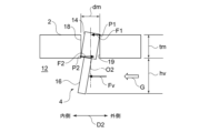
- Figure 3 is a diagram showing a schematic state of the variable nozzle device 1 according to one embodiment when exhaust gas G flows through the nozzle flow path 12.
- the fluid force acting on the vane blade 16 by the exhaust gas G is Fv
- the rotational moment due to the fluid force Fv generated around the rotation axis O2 is Tv
- the length of the hole 18 is tm
- the diameter of the vane shaft 14 is dm
- the height of the vane blade 16 is hv
- the friction coefficient of the vane shaft 14 with respect to the hole 18 is ⁇ .
- the variable nozzle device 1 according to one embodiment satisfies Tv> ⁇ dm/2 ⁇ Fv(1+hv/tm).
- the fluid force Fv is the magnitude of the force that the exhaust gas G acts on the vane blade 16 when the engine 200 is idling or operating at maximum rotation speed, for example.
- the fluid force Fv is the magnitude of the force that the exhaust gas G acts on the vane blade 16 immediately after the engine 200 is started.
- the fluid force Fv is a force generated in accordance with the pressure distribution generated around the vane blade 16 when the exhaust gas G flows through the nozzle passage 12 from the scroll passage 128 toward the turbine rotor 120. In some embodiments, the fluid force Fv is calculated by adding the pressure distribution of the nozzle passage 12 to the pressure distribution generated around the vane blade 16 when the exhaust gas G flows through the nozzle passage 12 from the scroll passage 128 toward the turbine rotor 120.
- the variable nozzle device 1 includes a link system (vane lever 8, drive ring 10, etc.) that are linked (connected) to each other to transmit the drive of the actuator 20 to the nozzle vane 4. If the rotational moment Tv of this link system becomes smaller than the friction torque Tf generated between the nozzle mount 2 and the nozzle vane 4, when the nozzle vane 4 is opened, for example, a contact position where the outer part 8b of the vane lever 8 and the inner circumferential surface of the fitting hole 11 of the drive ring 10 come into contact with each other changes, and so on, and a backlash occurs in the link system to make the link system function.
- a link system vane lever 8, drive ring 10, etc.
- variable nozzle device 1 In response to such concerns, the action and effect of the variable nozzle device 1 according to one embodiment will be described with reference to FIG. 3.
- the vane shaft 14 when a fluid force Fv acts on the vane blade 16, the vane shaft 14 inserted in the hole 18 tilts.
- the vane shaft 14 includes a first position P1 and a second position P2 at which the vane shaft 14 contacts the inner peripheral surface 19 of the hole 18.
- the nozzle vane 4 is supported at one end by the nozzle mount 2, but in another embodiment, the nozzle vane 4 is supported at both ends by both the nozzle mount 2 and the nozzle plate 6.
- FIG. 4 is a diagram showing a schematic state of the variable nozzle device 1 according to another embodiment when exhaust gas G flows through the nozzle flow passage 12.
- the nozzle vane 4 further includes a second vane shaft 26 provided at the tip of the vane blade 16 on the opposite side to the vane shaft 14 (first vane shaft) side in the direction in which the rotation axis O2 extends.
- the second vane shaft 26 is fitted into a second hole 28 formed in the nozzle plate 6.
- the hole 18 and the second hole 28 have the same diameter.
- the hole 18 and the second hole 28 are formed at the same position in the radial direction D2.
- the vane shaft 14 and the second vane shaft 26 have the same diameter.
- variable nozzle device 1 As shown in Figure 4, Fv is the fluid force acting on the vane blades 16 by the exhaust gas G, Tv is the rotational moment due to the fluid force generated around the rotation axis O2 of the nozzle vane 4, dm1 is the diameter of the vane shaft 14, dm2 is the diameter of the second vane shaft 26, ⁇ 1 is the first friction coefficient of the vane shaft 14 (first vane shaft) relative to the hole 18 (first hole), and ⁇ 2 is the second friction coefficient of the second vane shaft 26 relative to the second hole 28.
- the variable nozzle device 1 according to another embodiment satisfies Tv > Fv x ( ⁇ 1dm1 + ⁇ 2dm2)/4.
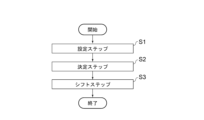
- FIG. 5 is a flowchart of the method for designing the variable nozzle device 1 according to one embodiment. As shown in Figure 5, the method for designing the variable nozzle device 1 includes a setting step S1 and a determining step S2.
- the fluid force acting on the vane blade 16 by the exhaust gas G, the rotational moment due to the fluid force generated around the rotation axis O2 of the nozzle vane 4, the length of the hole 18, the diameter of the vane shaft 14, the height of the vane blade 16, and the friction coefficient of the vane shaft 14 against the hole 18 are each set.
- the shapes of the nozzle mount 2 and the nozzle vane 4 are determined so as to satisfy the formula (1), where the fluid force set in the setting step S1 is Fv, the rotational moment is Tv, the length of the hole 18 is tm, the diameter of the vane shaft 14 is dm, the height of the vane blade 16 is hv, and the friction coefficient is ⁇ . Tv> ⁇ dm/2 ⁇ Fv(1+hv/tm)...(1)
- the shapes of the nozzle mount 2 and the nozzle vane 4 are determined so as to satisfy Tv> ⁇ dm/2 ⁇ Fv(1+hv/tm).
- the shapes of the nozzle mount 2 and the nozzle vane 4 are determined so as to satisfy rotational moment Tv>friction torque Tf. Therefore, no backlash occurs in the link system for operating the nozzle vane 4, whether the nozzle vane 4 is open or closed (for example, the contact position between the vane lever 8 and the drive ring 10 does not change). This improves the controllability of the opening degree of the nozzle vane 4.
- the determining step S2 determines the respective shapes of the nozzle mount 2 and the nozzle vanes 4 so as to satisfy equation (2). Tv/ ⁇ dm/2 ⁇ Fv(1+hv/tm) ⁇ >0.4...(2)
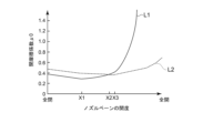
- Transforming equation (1) gives ⁇ >Tv/ ⁇ dm/2 ⁇ Fv(1+hv/tm) ⁇ . Then, Tv/ ⁇ dm/2 ⁇ Fv(1+hv/tm) ⁇ on the right side of this equation is defined as the opening friction coefficient ⁇ 0 at which the nozzle vane 4 can be opened.
- FIG. 6 is a graph showing the relationship between the opening friction coefficient ⁇ 0 and the opening degree of the nozzle vane 4, with the horizontal axis representing the opening degree of the nozzle vane 4 and the vertical axis representing the opening friction coefficient ⁇ 0. As shown in FIG. 6, the opening friction coefficient ⁇ 0 tends to increase as the opening degree of the nozzle vane 4 increases.
- FIG. 6 is a graph showing the relationship between the opening friction coefficient ⁇ 0 and the opening degree of the nozzle vane 4, with the horizontal axis representing the opening degree of the nozzle vane 4 and the vertical axis representing the opening friction coefficient ⁇ 0. As shown in FIG. 6, the opening friction coefficient ⁇ 0 tends to increase
- L1 and L2 are the opening degrees of the nozzle vane 4 having vane blades 16 (curved blades) designed for the purpose of rectifying the inlet flow of the turbine rotor blade.
- the sizes of the vane blades 16 are different between L1 and L2.
- the opening friction coefficient ⁇ 0 changes depending on the opening of the nozzle vane 4.
- the opening friction coefficient ⁇ 0 is approximately 0.3.
- the nozzle vane 4 cannot be opened by the fluid force Fv, and there is a risk of rattling occurring in the link system.
- the opening of the nozzle vane 4 that has a large effect on the controllability of the nozzle vane 4 is set to the second opening X2.
- the second opening X2 is included in a region with small openings (in FIG. 6, it is closer to fully closed than fully open). Then, as shown in FIG.
- the determining step S2 determines the respective shapes of the nozzle mount 2 and the nozzle vanes 4 so as to satisfy equation (3). dm/2 ⁇ (1+hv/tm) ⁇ 4...(3)
- Transforming equation (2) gives dm/2 ⁇ (1+hv/tm) ⁇ 2.5 ⁇ Tv/Fv.
- the shape of the nozzle vane 4 is changed to change Tv/Fv on the right-hand side of this equation, and CFD analysis is performed.
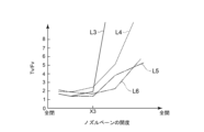
- Figure 7 is a graph showing the relationship between the nozzle vane 4 opening and Tv/Fv obtained by CFD analysis, with the horizontal axis representing the nozzle vane 4 opening and the vertical axis representing Tv/Fv. As shown in Figure 7, the greater the nozzle vane 4 opening, the greater the Tv/Fv tends to be.
- L3 to L6 are the openings of the nozzle vane 4, which have vane blades 16 (curved blades) designed for the purpose of streamlining the turbine rotor blade inlet flow.
- the vane blades 16 for L3 to L6 are different in size and shape from each other.
- Tv/Fv is approximately 1.5 to 2.0 mm.
- the determining step S2 determines the respective shapes of the nozzle mount 2 and the nozzle vane 4 so as to satisfy equation (4). 1+hv/tm ⁇ 2...(4)
- the diameter dm of the vane shaft 14 is often set to approximately 4 to 5 mm. Therefore, by determining the shapes of the nozzle mount 2 and the nozzle vane 4 so as to satisfy equation (4), it is possible to improve the controllability of the opening degree of the nozzle vane 4 when the diameter dm of the vane shaft 14 is set to 4 to 5 mm.
- the design method of the variable nozzle device 1 further includes a shift step S3.
- the shift step S3 after the determination step S2, the rotation axis O2 of the nozzle vane 4 is shifted 2 mm or more upstream of the nozzle flow path 12 from the position where the exhaust gas G acts on the vane blade 16, or by 10% or more of the chord length of the vane blade 16.
- the vane axis 14 is shifted 2 mm or more upstream of the nozzle flow path 12, or by 10% or more of the chord length of the vane blade 16.
- the upper limit of the amount by which the rotation axis O2 of the nozzle vane 4 is shifted is not particularly limited, but is set based on, for example, the output value of the actuator 20 and the amount of wear of the link system (upper limit of the contact load).
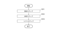
- FIG. 8 is a flowchart of a method for designing the variable nozzle device 1 according to another embodiment. As shown in Figure 8, the method for designing the variable nozzle device 1 includes a setting step S11 and a determination step S12.
- the setting step S11 sets the fluid force acting on the vane blades 16 by the exhaust gas G, the rotational moment due to the fluid force generated around the rotation axis O2 of the nozzle vane 4, the diameter of the vane shaft 14, the diameter of the second vane shaft 26, the first friction coefficient of the vane shaft 14 against the hole 18, and the second friction coefficient of the second vane shaft 26 against the second hole 28.
- the rotational moment is Tv
- the diameter of the vane shaft 14 is dm1
- the diameter of the second vane shaft 26 is dm2
- the first friction coefficient is ⁇ 1
- the second friction coefficient is ⁇ 2
- the shapes of the nozzle mount 2, the nozzle plate 6 and the nozzle vane 4 are determined so as to satisfy the formula (5).
- the shapes of the nozzle mount 2, nozzle plate 6, and nozzle vane 4 are determined so as to satisfy Tv>Fv ⁇ ( ⁇ 1dm1+ ⁇ 2dm2)/4.
- the shapes of the nozzle mount 2, nozzle plate 6, and nozzle vane 4 are determined so as to satisfy rotational moment Tv>friction torque Tf. Therefore, no backlash occurs in the link system for operating the nozzle vane 4, whether the nozzle vane 4 is open or closed (for example, the contact position between the vane lever and the drive ring does not change). This improves the controllability of the opening degree of the nozzle vane 4.
- the determining step S12 determines the respective shapes of the nozzle mount 2, the nozzle plate 6 and the nozzle vanes 4 so as to satisfy equation (6). Tv> ⁇ 1 ⁇ Fv ⁇ dm1/2...(6)
- the determining step S12 determines the shapes of each of the nozzle mount 2, the nozzle plate 6 and the nozzle vanes 4 so as to satisfy equation (7). Tv/ ⁇ Fv ⁇ (dm1+dm2) ⁇ >0.1...(7)
- the determining step S12 determines the shapes of each of the nozzle mount 2, the nozzle plate 6 and the nozzle vanes 4 so as to satisfy equation (8). Tv/(Fv ⁇ dm1)>0.2...(8)
- the design method of the variable nozzle device 1 further includes a shift step S13.
- the shift step S13 after the determination step S12, the rotation axis O2 of the nozzle vane 4 is shifted 2 mm or more upstream of the nozzle flow path 12 from the position where the exhaust gas G acts on the vane blade 16, or by 10% or more of the chord length of the vane blade 16.
- the vane axis 14 and the second vane axis 26 are each shifted 2 mm or more upstream of the nozzle flow path 12, or by 10% or more of the chord length of the vane blade 16.
- a method for designing a variable nozzle device (1) includes: A method for designing a variable nozzle device including a nozzle mount (2) and a nozzle vane (4) rotatably supported by the nozzle mount, the nozzle vane (4) having a vane shaft (14) inserted into a hole (18) formed in the nozzle mount and a vane blade (16) arranged in a nozzle flow passage (12) through which a fluid (G) flows, the method comprising the steps of: a setting step (S1) of setting a fluid force acting on the vane blade by the fluid, a rotational moment caused by the fluid force around a rotation axis (O2) of the nozzle vane, a length of the hole, a diameter of the vane shaft, a height of the vane blade, and a friction coefficient of the vane shaft with respect to the hole; a determining step (S2) of determining the respective shapes of the nozzle mount and the nozzle vane so as to satisfy the following formula (1), where the fluid force set in
- the shapes of the nozzle mount and the nozzle vane are determined so that Tv > ⁇ x dm/2 x Fv (1 + hv/tm). In other words, the shapes of the nozzle mount and the nozzle vane are determined so that rotational moment Tv > friction torque Tf. Therefore, no backlash occurs in the link system for operating the nozzle vane, whether the nozzle vane is open or closed (for example, the contact position between the vane lever and the drive ring does not change). This improves the controllability of the nozzle vane opening.
- the determining step determines the shapes of the nozzle mount and the nozzle vane so as to satisfy the following formula (2). Tv/ ⁇ dm/2 ⁇ Fv(1+hv/tm) ⁇ >0.4...(2)
- the determining step determines the shapes of the nozzle mount and the nozzle vane so as to satisfy the following formula (3). dm/2 ⁇ (1+hv/tm) ⁇ 4...(3)
- Transforming equation (2) gives dm/2 x (1 + hv/tm) ⁇ 2.5 x Tv/Fv.
- the determining step determines the shapes of the nozzle mount and the nozzle vane so as to satisfy the following formula (4). 1+hv/tm ⁇ 2...(4)
- the vane shaft diameter dm is often set to approximately 4 to 5. According to the method described in [4] above, it is possible to improve the controllability of the nozzle vane opening when the vane shaft diameter dm is set to 4 to 5.
- the method further includes a shift step (S3) of shifting the rotation axis of the nozzle vane by 2 mm or more upstream of the nozzle flow path from the position where the fluid acts on the vane blade, or by 10% or more of the chord length of the vane blade, after the determination step.
- S3 shift step of shifting the rotation axis of the nozzle vane by 2 mm or more upstream of the nozzle flow path from the position where the fluid acts on the vane blade, or by 10% or more of the chord length of the vane blade, after the determination step.
- a method for designing a variable nozzle device (1) includes: A method for designing a variable nozzle device including a nozzle mount (2), a nozzle plate (6) that defines a nozzle flow path (12) through which a fluid (G) flows between the nozzle mount and the nozzle plate, and a nozzle vane (4) rotatably supported by each of the nozzle mount and the nozzle plate, the nozzle vane having a first vane shaft (14) that is inserted into a first hole (18) formed in the nozzle mount, a second vane shaft (26) that is inserted into a second hole (28) formed in the nozzle plate, and a vane blade (16) that is arranged in the nozzle flow path, the method comprising the steps of: a setting step (S11) of setting a fluid force acting on the vane blade by the fluid, a rotational moment caused by the fluid force around a rotation axis of the nozzle vane, a diameter of the first vane shaft, a diameter of the second vane shaft
- the shapes of the nozzle mount, nozzle plate, and nozzle vane are determined so that Tv > Fv x ( ⁇ 1dm1 + ⁇ 2dm2)/4 is satisfied.
- the shapes of the nozzle mount, nozzle plate, and nozzle vane are determined so that the rotational moment Tv > friction torque Tf is satisfied.
- the determining step determines the shapes of the nozzle mount, the nozzle plate, and the nozzle vane so as to satisfy the following formula (6). Tv> ⁇ 1 ⁇ Fv ⁇ dm1/2...(6)
- the determining step determines the shapes of the nozzle mount, the nozzle plate, and the nozzle vane so as to satisfy the following formula (7). Tv/ ⁇ Fv ⁇ (dm1+dm2) ⁇ >0.1...(7)
- the determining step determines the shapes of the nozzle mount, the nozzle plate, and the nozzle vane so as to satisfy the following formula (8). Tv/(Fv ⁇ dm1)>0.2...(8)
- the variable nozzle device (1) is A nozzle mount (2); a nozzle vane (4) rotatably supported by the nozzle mount, the nozzle vane including a vane shaft (14) inserted into a hole (18) formed in the nozzle mount and a vane blade (16) disposed in a nozzle flow passage (12) through which a fluid (G) flows;
- Fv be the fluid force acting on the vane blade by the fluid
- Tv be the rotational moment caused by the fluid force around the rotation axis (O2) of the nozzle vane
- tm be the length of the hole
- dm the diameter of the vane shaft
- hv the height of the vane blade
- ⁇ be the friction coefficient of the vane shaft with respect to the hole.
- Tv> ⁇ dm/2 ⁇ Fv(1+hv/tm) is satisfied.
- the variable nozzle device (1) is A nozzle mount (2); a nozzle plate (6) defining a nozzle flow passage (12) through which a fluid (G) flows between the nozzle plate and the nozzle mount; a nozzle vane (4) rotatably supported by each of the nozzle mount and the nozzle plate, the nozzle vane (4) including a first vane shaft (14) inserted into a first hole (18) formed in the nozzle mount, a second vane shaft (26) inserted into a second hole (28) formed in the nozzle plate, and a vane blade (16) disposed in the nozzle flow path;
- Fv be the fluid force acting on the vane blade by the fluid
- Tv be the rotational moment caused by the fluid force generated around the rotation axis (O2) of the nozzle vane
- dm1 be the diameter of the first vane shaft
- dm2 be the diameter of the second vane shaft
- ⁇ 1 be the first friction coefficient of the first vane shaft with respect to the first hole
Landscapes
- Engineering & Computer Science (AREA)
- Mechanical Engineering (AREA)
- General Engineering & Computer Science (AREA)
- Chemical & Material Sciences (AREA)
- Combustion & Propulsion (AREA)
- Control Of Turbines (AREA)
- Supercharger (AREA)
Priority Applications (4)
| Application Number | Priority Date | Filing Date | Title |
|---|---|---|---|
| JP2025509541A JPWO2024201947A1 (https=) | 2023-03-30 | 2023-03-30 | |
| CN202380095990.9A CN120917217A (zh) | 2023-03-30 | 2023-03-30 | 可变喷嘴装置的设计方法及可变喷嘴装置 |
| PCT/JP2023/013367 WO2024201947A1 (ja) | 2023-03-30 | 2023-03-30 | 可変ノズル装置の設計方法、および可変ノズル装置 |
| DE112023005557.2T DE112023005557T5 (de) | 2023-03-30 | 2023-03-30 | Verfahren zum entwerfen von variabler düsenvorrichtung und variable düsenvorrichtung |
Applications Claiming Priority (1)
| Application Number | Priority Date | Filing Date | Title |
|---|---|---|---|
| PCT/JP2023/013367 WO2024201947A1 (ja) | 2023-03-30 | 2023-03-30 | 可変ノズル装置の設計方法、および可変ノズル装置 |
Publications (1)
| Publication Number | Publication Date |
|---|---|
| WO2024201947A1 true WO2024201947A1 (ja) | 2024-10-03 |
Family
ID=92904423
Family Applications (1)
| Application Number | Title | Priority Date | Filing Date |
|---|---|---|---|
| PCT/JP2023/013367 Ceased WO2024201947A1 (ja) | 2023-03-30 | 2023-03-30 | 可変ノズル装置の設計方法、および可変ノズル装置 |
Country Status (4)
| Country | Link |
|---|---|
| JP (1) | JPWO2024201947A1 (https=) |
| CN (1) | CN120917217A (https=) |
| DE (1) | DE112023005557T5 (https=) |
| WO (1) | WO2024201947A1 (https=) |
Citations (3)
| Publication number | Priority date | Publication date | Assignee | Title |
|---|---|---|---|---|
| WO2020100222A1 (ja) * | 2018-11-13 | 2020-05-22 | 三菱重工エンジン&ターボチャージャ株式会社 | ノズルベーン |
| US20220282636A1 (en) * | 2021-03-03 | 2022-09-08 | Garrett Transportation I Inc | Bi-metal variable geometry turbocharger vanes and methods for manufacturing the same using laser cladding |
| WO2022259779A1 (ja) * | 2021-06-08 | 2022-12-15 | 株式会社Ihi | タービン及び過給機 |
-
2023
- 2023-03-30 JP JP2025509541A patent/JPWO2024201947A1/ja active Pending
- 2023-03-30 WO PCT/JP2023/013367 patent/WO2024201947A1/ja not_active Ceased
- 2023-03-30 CN CN202380095990.9A patent/CN120917217A/zh active Pending
- 2023-03-30 DE DE112023005557.2T patent/DE112023005557T5/de active Pending
Patent Citations (3)
| Publication number | Priority date | Publication date | Assignee | Title |
|---|---|---|---|---|
| WO2020100222A1 (ja) * | 2018-11-13 | 2020-05-22 | 三菱重工エンジン&ターボチャージャ株式会社 | ノズルベーン |
| US20220282636A1 (en) * | 2021-03-03 | 2022-09-08 | Garrett Transportation I Inc | Bi-metal variable geometry turbocharger vanes and methods for manufacturing the same using laser cladding |
| WO2022259779A1 (ja) * | 2021-06-08 | 2022-12-15 | 株式会社Ihi | タービン及び過給機 |
Also Published As
| Publication number | Publication date |
|---|---|
| DE112023005557T5 (de) | 2025-11-27 |
| CN120917217A (zh) | 2025-11-07 |
| JPWO2024201947A1 (https=) | 2024-10-03 |
Similar Documents
| Publication | Publication Date | Title |
|---|---|---|
| US9932843B2 (en) | Double flow turbine housing turbocharger | |
| US8844282B2 (en) | Exhaust-gas turbocharger having a ball-cock waste-gate valve with a stress-relieved crank arm | |
| EP2636868B1 (en) | Turbine housing for twin scroll turbocharger | |
| JP4875644B2 (ja) | タービンおよびこれを備えるターボチャージャ | |
| JP3719337B2 (ja) | 遠心式圧縮機 | |
| KR101267193B1 (ko) | 가변 용량 터빈 | |
| JP5890021B2 (ja) | 排気ガスターボチャージャーのタービン | |
| KR20150095830A (ko) | 단일 밸브를 구비한 혼류 트윈 스크롤 터보차저 | |
| JP3326615B2 (ja) | 内燃機関ターボ過給機システム | |
| JP4797788B2 (ja) | ターボチャージャ | |
| CN111148903A (zh) | 用于内燃发动机的增压装置的具有虹膜式隔板机构的径流式压缩机、增压装置和虹膜式隔板机构的叶片 | |
| JP2016056804A (ja) | ターボチャージャの排気タービン | |
| CN111148901B (zh) | 用于内燃发动机的增压装置的包括虹膜式隔板机构的径流式压缩机、增压装置和虹膜式隔板机构的薄片 | |
| JP5807037B2 (ja) | 可変ノズルターボチャージャ | |
| US20120023938A1 (en) | Variable capacity supercharger for internal combustion engine | |
| WO2024201947A1 (ja) | 可変ノズル装置の設計方法、および可変ノズル装置 | |
| JP4415447B2 (ja) | 可変容量ターボチャージャ | |
| CN111094756B (zh) | 径向压缩机、增压装置和薄片以及制造这种薄片的方法 | |
| JP5087160B2 (ja) | タービンおよびこれを備えるターボチャージャ | |
| US20040062638A1 (en) | Turbine for an exhaust gas turbocharger | |
| CN109312755A (zh) | 具有可变压缩机入口的压缩机 | |
| EP3225787B1 (en) | Turbocharger with variable nozzle mechanism | |
| JP5974501B2 (ja) | ターボ機械の可変静翼機構 | |
| CN102482948A (zh) | 涡轮增压器的导向叶片、导向叶片装置、涡轮增压器、汽车和方法 | |
| JP2003027951A (ja) | 可変容量型過給機の流量増加構造 |
Legal Events
| Date | Code | Title | Description |
|---|---|---|---|
| 121 | Ep: the epo has been informed by wipo that ep was designated in this application |
Ref document number: 23930584 Country of ref document: EP Kind code of ref document: A1 |
|
| ENP | Entry into the national phase |
Ref document number: 2025509541 Country of ref document: JP Kind code of ref document: A |
|
| WWE | Wipo information: entry into national phase |
Ref document number: 2025509541 Country of ref document: JP |
|
| WWE | Wipo information: entry into national phase |
Ref document number: 112023005557 Country of ref document: DE |
|
| WWE | Wipo information: entry into national phase |
Ref document number: CN2023800959909 Country of ref document: CN Ref document number: 202380095990.9 Country of ref document: CN |
|
| WWP | Wipo information: published in national office |
Ref document number: 202380095990.9 Country of ref document: CN |
|
| WWP | Wipo information: published in national office |
Ref document number: 112023005557 Country of ref document: DE |
|
| 122 | Ep: pct application non-entry in european phase |
Ref document number: 23930584 Country of ref document: EP Kind code of ref document: A1 |