WO2024201944A1 - タービン及びターボチャージャ - Google Patents
タービン及びターボチャージャ Download PDFInfo
- Publication number
- WO2024201944A1 WO2024201944A1 PCT/JP2023/013359 JP2023013359W WO2024201944A1 WO 2024201944 A1 WO2024201944 A1 WO 2024201944A1 JP 2023013359 W JP2023013359 W JP 2023013359W WO 2024201944 A1 WO2024201944 A1 WO 2024201944A1
- Authority
- WO
- WIPO (PCT)
- Prior art keywords
- housing
- turbine
- plate portion
- flow path
- turbine wheel
- Prior art date
- Legal status (The legal status is an assumption and is not a legal conclusion. Google has not performed a legal analysis and makes no representation as to the accuracy of the status listed.)
- Ceased
Links
Images




Classifications
-
- F—MECHANICAL ENGINEERING; LIGHTING; HEATING; WEAPONS; BLASTING
- F02—COMBUSTION ENGINES; HOT-GAS OR COMBUSTION-PRODUCT ENGINE PLANTS
- F02B—INTERNAL-COMBUSTION PISTON ENGINES; COMBUSTION ENGINES IN GENERAL
- F02B37/00—Engines characterised by provision of pumps driven at least for part of the time by exhaust
- F02B37/12—Control of the pumps
- F02B37/24—Control of the pumps by using pumps or turbines with adjustable guide vanes
-
- F—MECHANICAL ENGINEERING; LIGHTING; HEATING; WEAPONS; BLASTING
- F01—MACHINES OR ENGINES IN GENERAL; ENGINE PLANTS IN GENERAL; STEAM ENGINES
- F01D—NON-POSITIVE DISPLACEMENT MACHINES OR ENGINES, e.g. STEAM TURBINES
- F01D9/00—Stators
- F01D9/02—Nozzles; Nozzle boxes; Stator blades; Guide conduits, e.g. individual nozzles
- F01D9/04—Nozzles; Nozzle boxes; Stator blades; Guide conduits, e.g. individual nozzles forming ring or sector
- F01D9/045—Nozzles; Nozzle boxes; Stator blades; Guide conduits, e.g. individual nozzles forming ring or sector for radial flow machines or engines
-
- F—MECHANICAL ENGINEERING; LIGHTING; HEATING; WEAPONS; BLASTING
- F05—INDEXING SCHEMES RELATING TO ENGINES OR PUMPS IN VARIOUS SUBCLASSES OF CLASSES F01-F04
- F05D—INDEXING SCHEME FOR ASPECTS RELATING TO NON-POSITIVE-DISPLACEMENT MACHINES OR ENGINES, GAS-TURBINES OR JET-PROPULSION PLANTS
- F05D2220/00—Application
- F05D2220/40—Application in turbochargers
-
- F—MECHANICAL ENGINEERING; LIGHTING; HEATING; WEAPONS; BLASTING
- F05—INDEXING SCHEMES RELATING TO ENGINES OR PUMPS IN VARIOUS SUBCLASSES OF CLASSES F01-F04
- F05D—INDEXING SCHEME FOR ASPECTS RELATING TO NON-POSITIVE-DISPLACEMENT MACHINES OR ENGINES, GAS-TURBINES OR JET-PROPULSION PLANTS
- F05D2260/00—Function
- F05D2260/30—Retaining components in desired mutual position
- F05D2260/38—Retaining components in desired mutual position by a spring, i.e. spring loaded or biased towards a certain position
Definitions
- This disclosure relates to turbines and turbochargers.
- Patent Document 1 discloses a support structure in which the fixed nozzle is integrated with an annular nozzle ring that supports the fixed nozzle, and the outer peripheral end of the nozzle ring is clamped between the turbine casing and the bearing base, thereby supporting the fixed nozzle.
- the nozzle ring has an outer peripheral end that is in contact with a bearing base that is relatively cool, while an inner peripheral end is exposed to exhaust gas that is relatively hot. This causes a temperature distribution on the inner and outer periphery of the nozzle ring, which generates relatively high thermal stress in the nozzle ring, and may lead to thermal fatigue damage to the nozzle ring.
- a spring member that supports the nozzle ring is sometimes placed on the turbine, but it is sometimes unable to keep up with temperature changes in the exhaust gas introduced into the turbine, and the spring member's biasing force does not act on the nozzle ring.
- At least one embodiment of the present disclosure aims to provide a turbine and turbocharger that can continuously support a nozzle device during turbine operation and can reduce thermal stresses that occur in the nozzle device.
- a turbine includes: A turbine wheel; a first housing having a scroll flow passage; a second housing connected to the first housing, accommodating the turbine wheel between the first housing and the second housing, and forming a gas flow passage from the scroll flow passage toward the turbine wheel between the first housing and the second housing; a first annular plate portion having a first flow path surface facing the gas flow path and a first back surface that is a surface on the opposite side of the turbine wheel in the axial direction from the first flow path surface, the first back surface forming a first space between the first housing and the second housing; and at least one stationary nozzle vane fixed or supported by the first plate portion and extending along the axial direction in the gas flow path;
- a nozzle device including at least The compressor further includes a biasing member disposed in the first space and configured to bias the at least one stationary nozzle vane toward the first housing via the first plate portion.
- a turbocharger includes: The turbine; and a centrifugal compressor configured to be driven by the turbine.
- At least one embodiment of the present disclosure provides a turbine and turbocharger that can continuously support the nozzle device while the turbine is in operation and can reduce thermal stresses on the nozzle device.
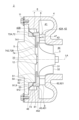
- FIG. 1 is a schematic cross-sectional view of a turbine along its axis according to an embodiment of the present disclosure
- FIG. 1 is a schematic diagram of a turbine nozzle device according to an embodiment of the present disclosure, viewed from one side in the axial direction.
- FIG. 2 is a schematic cross-sectional view taken along the axis of a turbine according to a comparative example.
- FIG. 2 is an explanatory diagram for explaining a temperature change of a working fluid introduced into a turbine according to an embodiment of the present disclosure.
- 7 is an explanatory diagram for explaining a change in biasing force applied to a nozzle device of a turbine according to a comparative example.
- FIG. 1 is a schematic cross-sectional view of a turbine along its axis according to an embodiment of the present disclosure
- FIG. 1 is a schematic diagram of a turbine nozzle device according to an embodiment of the present disclosure, viewed from one side in the axial direction.
- FIG. 2 is a schematic cross-sectional view taken
- FIG. 5 is an explanatory diagram for explaining a change in biasing force applied to a nozzle device of a turbine according to an embodiment of the present disclosure.
- FIG. 1 is a schematic cross-sectional view of a turbine along its axis according to an embodiment of the present disclosure;
- FIG. 1 is a schematic cross-sectional view of a turbine along its axis according to an embodiment of the present disclosure;
- FIG. 1 is a schematic cross-sectional view of a turbine along its axis according to an embodiment of the present disclosure;
- FIG. 1 is a schematic cross-sectional view of a turbine along its axis according to an embodiment of the present disclosure;
- FIG. 1 is a schematic cross-sectional view of a turbine along its axis according to an embodiment of the present disclosure;
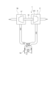
- FIG. 1 is a schematic diagram of a turbocharger according to an embodiment of the present disclosure.
- Fig. 1 is a schematic cross-sectional view along an axis line LA of a turbine 2 according to an embodiment of the present disclosure.
- the turbine 2 according to some embodiments includes a turbine wheel 3, a first housing (turbine housing) 4 having a scroll passage 41, a second housing (bearing housing) 5, a nozzle device 6, and a biasing member 9.
- the second housing 5 is connected to the first housing 4 via a fastening member such as a bolt 11, and accommodates the turbine wheel 3, the nozzle device 6, and the biasing member 9 between the second housing 5 and the first housing 4.
- the second housing 5 forms a gas passage 42A between the second housing 5 and the first housing 4, which guides gas from the scroll passage 41 toward the turbine wheel 3.
- the direction in which the axis LA of the turbine wheel 3 extends is referred to as the axial direction of the turbine wheel 3, the direction perpendicular to the axis LA is referred to as the radial direction of the turbine wheel 3, and the circumferential direction around the axis LA is referred to as the circumferential direction of the turbine wheel 3.
- the axial, radial, and circumferential directions of the turbine wheel 3 may be simply referred to as the axial, radial, and circumferential directions, respectively.
- the side where the first housing 4 is located relative to the second housing 5 the right side in FIG.
- the turbine wheel 3 is configured to guide gas introduced from the outside in the radial direction (e.g., exhaust gas discharged from an internal combustion engine or a fuel cell, not shown) to the front side along the axial direction.
- gas introduced from the outside in the radial direction e.g., exhaust gas discharged from an internal combustion engine or a fuel cell, not shown
- the turbine wheel 3 includes a hub 31 having a generally truncated cone shape and a plurality of turbine blades 32 provided on the outer peripheral surface of the hub 31.
- Each of the plurality of turbine blades 32 is arranged at intervals from one another in the circumferential direction around the axis line LA.
- the hub 31 is attached to one side of the rotating shaft 12.
- the hub 31 and the plurality of turbine blades 32 are rotatable integrally with the rotating shaft 12 around the axis line LA.
- the turbine wheel 3 and the rotating shaft 12 are rotatably supported by the second housing 5.
- Each of the plurality of turbine blades 32 is arranged with a predetermined gap from the shroud surface 43, which is the inner surface of the first housing 4.
- the turbine wheel 3 is an open-type impeller that does not include an annular member surrounding the outer periphery of the turbine blades 32.
- Scroll passage Inside the first housing 4, there are formed the above-mentioned scroll passage 41 for guiding gas for rotating the turbine wheel 3 to the turbine wheel 3, and a gas exhaust passage 44 for exhausting gas that has passed through the turbine wheel 3 to the outside of the first housing 4 (turbine 2).
- the scroll passage 41 is provided on the outer periphery side (outside in the radial direction) of the turbine wheel 3, and is composed of a spiral passage extending along the circumferential direction so as to surround the periphery of the turbine wheel 3.
- the gas exhaust passage 44 extends toward the front side along the axial direction.
- an internal space 42 is formed between the first housing 4 and the second housing 5, connecting the scroll passage 41 and the gas exhaust passage 44.
- the turbine wheel 3 is accommodated in the internal space 42 so as to be rotatable relative to the first housing 4 and the second housing 5.
- the turbine wheel 3 is disposed on the inner circumferential side (inner side in the radial direction) of the scroll passage 41.
- Gas which is the working fluid of the turbine 2
- the working fluid that drives the turbine wheel 3 to rotate is discharged to the outside of the turbine 2 through the gas discharge passage 44.
- the nozzle device 6 includes at least an annular first plate portion 7 and at least one fixed nozzle vane 8 that is fixed or supported by the first plate portion 7 and extends along the axial direction in the gas flow path 42A.
- the nozzle device 6 is accommodated in the internal space 42 to form the gas flow path 42A.
- the first plate portion 7 is configured to form a gas flow passage 42A from the scroll flow passage 41 toward the turbine wheel 3 between itself and another member (the first housing 4 in FIG. 1 ).
- the gas flow passage 42A is provided between the scroll flow passage 41 and the turbine wheel 3 in the radial direction so as to surround the outer periphery of the turbine wheel 3.
- the gas flow passage 42A is a part of the internal space 42, and is formed on the outer periphery side of the accommodation space that accommodates the turbine wheel 3 in the internal space 42.
- the first plate portion 7 is located rearward of the gas flow passage 42A.
- the first plate portion 7 has an annular first flow path surface 71 that faces the gas flow path 42A on one side in the thickness direction of the first plate portion 7, i.e., the front side.
- the first plate portion 7 has an annular first back surface 72 on the other side in the thickness direction of the first plate portion 7 (the side opposite to the first flow path surface 71), i.e., the rear side.
- FIG. 2 is a schematic diagram of the nozzle device 6 of the turbine 2 according to an embodiment of the present disclosure, viewed from the front side, which is one side in the axial direction.
- the at least one stationary nozzle vane 8 includes a plurality of stationary nozzle vanes 8 arranged at intervals from one another in the circumferential direction of the turbine wheel 3.
- the plurality of stationary nozzle vanes 8 are fixed to the first plate portion 7, and protrude from the first flow path surface 71 toward the first housing 4 (the front side).
- each of the multiple fixed nozzle vanes 8 is formed integrally with the first plate portion 7, and one end (rear side) in the axial direction is connected to the first flow path surface 71. As a result, each of the multiple fixed nozzle vanes 8 is fixed to the first flow path surface 71.
- Each of the multiple fixed nozzle vanes 8 has a forward end surface 821 formed at the end 82 on the opposite side (forward side) to the end 81 on the one side connected to the first plate portion 7, a leading edge 83, a trailing edge 84, and an inner blade surface 85 and an outer blade surface 86 each extending from the leading edge 83 to the trailing edge 84.
- Each of the multiple fixed nozzle vanes 8 has its trailing edge 84 located radially inward of its leading edge 83.
- Each of the multiple fixed nozzle vanes 8 has a blade surface that faces the gas flow path 42A, which is formed by the leading edge 83, the trailing edge 84, the inner blade surface 85, and the outer blade surface 86.
- the first housing 4 has a housing-side flow passage surface 47 that extends from the outer peripheral end of the shroud surface 43 toward the outside in the radial direction.
- the housing-side flow passage surface 47 extends along the circumferential direction and is an annular surface facing the gas flow passage 42A.
- the housing-side flow passage surface 47 is located forward of the first flow passage surface 71 of the first plate portion 7 in the axial direction and faces the first flow passage surface 71 across the gas flow passage 42A.
- the gas flow passage 42A is formed by the first flow passage surface 71 and the housing-side flow passage surface 47.
- each of the multiple fixed nozzle vanes 8 has a forward end surface 821 that abuts against the housing side flow passage surface 47.
- the first back surface 72 of the first plate portion 7 is configured to form a first space 42B between the first housing 4 and the second housing 5.
- the second housing 5 is disposed rearward of the turbine wheel 3 and the first plate portion 7.
- the second housing 5 has an end face 51 on the first housing 4 side (front side), and an outward protrusion 52 that protrudes outward in the radial direction beyond the outer edge of the end face 51 rearward of the end face 51.
- the second housing 5 has an outer peripheral surface 54 that extends from the outer edge of the end face 51 toward the rear side along the axial direction and is connected to the inner edge of the step surface 53.
- the first housing 4 has a rear scroll flow passage surface 451 that faces the rear side of the scroll flow passage 41, and has an inward protrusion 45 that extends inward in the radial direction along the radial direction.
- the first housing 4 has an inner circumferential surface 46 that extends in the circumferential direction on the rear side of the inward protrusion 45.
- the inner circumferential surface 46 faces the outer circumferential surface 54 in the radial direction with a gap therebetween.
- the inward protrusion 45 has an annular surface 452 that extends along the circumferential direction on the side opposite the rear scroll flow passage surface 451 in the thickness direction, i.e., on the rear side.
- the annular surface 452 extends inward in the radial direction from the front end of the inner circumferential surface 46 and faces the step surface 53 in the axial direction with a gap therebetween.
- the first plate portion 7 is disposed radially inwardly of the inward protrusion 45.
- the first back surface 72 of the first plate portion 7 includes a first outer peripheral back surface 72A that faces the step surface 53 with a gap in the axial direction, and a first inner peripheral back surface 72B that faces the end face 51 with a gap in the axial direction.
- the first outer peripheral back surface 72A is located radially outwardly of the first inner peripheral back surface 72B and is the rear end surface of the rear protrusion 73 that protrudes rearwardly from the first inner peripheral back surface 72B.
- the first outer peripheral back surface 72A is positioned rearwardly of the end face 51.
- the above-mentioned first space 42B is formed by the first outer circumferential back surface 72A of the rearward protruding portion 73 of the first plate portion 7, the annular surface 452 and inner circumferential surface 46 of the first housing 4, and the stepped surface 53 and outer circumferential surface 54 of the second housing 5.
- the first space 42B is surrounded by the first plate portion 7, the first housing 4, and the second housing 5, so that heat from the gas introduced into the turbine wheel 3 is less likely to flow into it than into the gap between the back surface 33 of the turbine wheel 3 and the end face 51 of the second housing 5 or into the gas flow path 42A.
- the biasing member 9 is disposed in the first space 42 ⁇ /b>B, and is configured to bias at least one stationary nozzle vane 8 toward the first housing 4 via the first plate portion 7 .
- the biasing member 9 is an annular elastic member disposed in a compressed state in the axial direction between the step surface 53 of the second housing 5 and the first outer circumferential back surface 72A of the first plate portion 7.
- the step surface 53 receives a reaction force of the biasing member 9, so that the biasing member 9 biases the first outer circumferential back surface 72A toward the first housing 4 (forward).
- the biasing force of the biasing member 9 that biases the nozzle device 6 is F1.
- the nozzle device 6 is supported between the biasing member 9 and the first housing 4 in the axial direction by the biasing force F1 of the biasing member 9.
- the first housing 4 is configured so that only the housing side flow path surface 47 limits the movement of the nozzle device 6 along the axial direction.
- the nozzle device 6 is not in contact with the biasing member 9, and the movement is not limited by the inward protrusion 45 even if it moves along the axial direction due to the biasing force F1 of the biasing member 9.
- the biasing force F1 preferably acts on a radial position as close as possible to the radial position where the fixed nozzle vanes 8 are present, and more preferably acts on the radial position.
- an imaginary circle that has the axis A of the nozzle device 6 as its origin and passes through the leading edge 83 that is located on the outermost side in the radial direction among the multiple fixed nozzle vanes 8 is defined as an outer virtual circle VC1
- an imaginary circle that has the axis A as its origin and passes through the trailing edge 84 that is located on the innermost side in the radial direction among the multiple fixed nozzle vanes 8 is defined as an inner virtual circle VC2.
- the radial position where the fixed nozzle vanes 8 are present as described above means a position that is radially inward from the outer virtual circle VC1 and radially outward from the inner virtual circle VC2.
- the turbine 2 further includes a heat shield (back plate) 13 having a first opposing surface 131 that faces the back surface 33 of the turbine wheel 3 with a gap therebetween in the axial direction.
- the heat shield 13 has a first plate portion side abutting portion 132 that abuts against the first plate portion 7 on the outer circumferential side of the first opposing surface 131, and a second housing side abutting portion 133 that abuts against the second housing 5.
- the heat shield 13 is formed in an annular shape in which the first plate-side abutment portion 132 abuts against the first inner circumferential back surface 72B, and the second housing-side abutment portion 133 abuts against the end face 51 on the inner circumferential side of the first plate-side abutment portion 132.
- the heat shield 13 is inclined toward the rear side from the outer circumferential end toward the inner circumferential end.
- the heat shield 13 is an annular disc spring arranged in a compressed state in the axial direction between the first inner circumferential back surface 72B and the end face 51.
- the end face 51 receives the reaction force of the heat shield 13, so that the first inner circumferential back surface 72B is biased toward the first housing 4 side (forward side). It is preferable that the biasing force of the heat shield 13 acts at a radial position as close as possible to the radial position where the fixed nozzle vane 8 is present, and it is even more preferable that it acts at the radial position.
- Figure 3 is a schematic cross-sectional view along the axis LA of a turbine 02 according to a comparative example.
- the turbine 02 according to the comparative example includes the turbine wheel 3, first housing 4, second housing 5, and heat shield member (back plate) 13 described above.
- the turbine 02 further includes a nozzle device 06 including an annular nozzle ring 07 and a plurality of fixed nozzle vanes 8 fixed to the nozzle ring 07.
- the turbine 02 includes an annular seal ring 09 instead of a biasing member 9.
- the nozzle ring 07 has an annular first flow passage surface 071 facing the gas flow passage 42A, and an annular first back surface 072 provided on the opposite side of the first flow passage surface 071 of the first plate portion 7.
- the outer peripheral end 073 of the nozzle ring 07 is clamped between the inward protrusion 45 of the first housing 4 and the outward protrusion 52 of the second housing 5, suppressing deformation.
- the outer peripheral end 073 is in contact with the second housing 5, which has a relatively low temperature.
- the inner peripheral end of the nozzle ring 07 is exposed to a working fluid (e.g., exhaust gas discharged from the engine 15) that has a relatively high temperature.
- a working fluid e.g., exhaust gas discharged from the engine 15
- the outer diameter of the nozzle ring 07 needs to be large, which may increase the cost of the parts.
- annular seal ring 09 inserted into an annular recess 471 formed in the housing-side flow passage surface 47 biases the multiple fixed nozzle vanes 8 toward the rear side in the axial direction of the turbine wheel 3 via an annular plate that abuts against the multiple fixed nozzle vanes 8.
- the biasing force of the annular seal ring 09 biasing the nozzle ring 07 is F0.
- FIG. 4 is an explanatory diagram for explaining the temperature change of the working fluid introduced into the turbine 2 according to one embodiment of the present disclosure.
- FIG. 5 is an explanatory diagram for explaining the change in the biasing force F0 applied to the nozzle device 06 of the turbine 02 according to a comparative example.
- FIG. 6 is an explanatory diagram for explaining the change in the biasing force F1 applied to the nozzle device 6 of the turbine 2 according to one embodiment of the present disclosure.
- the horizontal axis represents time T (T1 to T4).
- the vertical axis represents the temperature (inlet temperature) GT of the working fluid (gas) introduced into the turbine 2.
- the vertical axis represents the biasing force F0
- the vertical axis represents the biasing force F1.
- the temperature GT changes over time during operation of the turbine 2, and there are high-temperature periods when the temperature is relatively high and low-temperature periods when the temperature is relatively low.
- the biasing force F0 does not act effectively when the temperature GT transitions from high to low. Since the nozzle device 06 cools down first compared to the first housing 4, the gap between the nozzle ring 07 and the housing side flow path surface 47 becomes large, and the spring force of the annular seal ring 09 may not act.
- the biasing force F1 continues to act during operation of the turbine 2, including when the temperature GT transitions from high to low.
- the biasing force F1 acts to reduce the clearance between the first housing 4 and the fixed nozzle vane 8, thereby reducing the clearance flow, thereby improving the performance of the turbine 2.
- the turbine 2 includes the turbine wheel 3, the first housing 4, the second housing 5, the nozzle device 6, and the biasing member 9 described above.
- the above configuration supports the first plate portion 7 and the fixed nozzle vane 8 with the biasing force F1 of the biasing member 9, thereby preventing the first plate portion 7 from coming into contact with the second housing 5, which has a relatively low temperature, and thus preventing temperature distribution in the first plate portion 7, thereby reducing thermal stress in the first plate portion 7.
- the flow of heat from the first plate portion 7 to the second housing 5 can be suppressed. This reduces heat loss in the turbine 2, thereby improving the high-temperature performance (thermal efficiency) of the turbine 2.
- the biasing member 9 is disposed in the first space 42B, which has smaller temperature fluctuations during operation of the turbine 2 than the gas flow path 42A and is maintained at a relatively low temperature, so the temperature of the biasing member 9 can be maintained at a relatively low temperature. This makes it possible to suppress thermal settling of the biasing member 9 (plastic deformation or creep deformation due to heat) and suppress a reduction in the biasing force F1 of the biasing member 9 due to the thermal settling.
- the biasing force F1 of the biasing member 9 can be continuously applied to the first plate portion 7 and the fixed nozzle vane 8 during operation of the turbine 2, so that the first plate portion 7 and the fixed nozzle vane 8 can be continuously supported during operation of the turbine 2.
- the area over which the biasing force F1 acts can be made larger than when the fixed nozzle vane 8 is directly biased by the biasing member 9. This allows the biasing force F1 of the biasing member 9 to be continuously and stably applied to the fixed nozzle vane 8 while the turbine 2 is in operation.
- the first housing 4 described above has a housing-side flow passage surface 47 that is an abutment surface against which the end face 821 of each of the multiple fixed nozzle vanes 8 abuts on the side opposite to the side fixed to the first plate portion 7.
- the biasing force F1 of the biasing member 9 causes the end face 821 of the fixed nozzle vane 8 to adhere closely to the housing side flow path surface 47 of the first housing 4, eliminating the gap in the axial direction between the fixed nozzle vane 8 and the first housing 4, thereby suppressing the gas flow passing through the gap and improving the performance of the turbine 2. Furthermore, with the above configuration, the number of parts of the turbine 2 can be reduced compared to when other parts are sandwiched between the fixed nozzle vane 8 and the first housing 4, making it easier to assemble the turbine 2 and reducing the manufacturing cost of the turbine 2.
- the first plate portion 7 and each of the plurality of fixed nozzle vanes 8 described above are integrally formed.
- the number of parts of the turbine 2 can be reduced compared to when the first plate portion 7 and each of the plurality of fixed nozzle vanes 8 are separate, and the assembly of the turbine 2 is made easier, thereby reducing the manufacturing cost of the turbine 2.
- FIG. 7 to 11 is a schematic cross-sectional view taken along the axis LA of the turbine 2 according to one embodiment of the present disclosure.
- the turbine 2 according to the embodiment shown in Figures 7 to 11 also achieves the same effects as those described for the turbine 2 according to the embodiment shown in Figure 1.
- the turbine 2 according to the embodiment shown in Figures 7 to 11 includes the turbine wheel 3, first housing 4, second housing 5, nozzle device 6, and biasing member 9 described above.
- the nozzle device 6 further includes an annular second plate portion 14 extending along the circumferential direction.
- the second plate portion 14 has an annular second flow path surface 141 on one side in the thickness direction of the second plate portion 14, i.e., on the rear side, which faces the first flow path surface 71 across the gas flow path 42A.
- the second plate portion 14 has an annular second back surface 142 on the other side in the thickness direction of the second plate portion 14 (the side opposite to the second flow path surface 141), i.e., on the front side.
- the second flow path surface 141 is supported or fixed at an end 82 on the opposite side (front side) to an end 81 that is fixed or supported by the first plate portion 7 of each of the multiple fixed nozzle vanes 8.
- the second back surface 142 is adapted to abut against the first housing 4.
- the nozzle device 6 including the second plate portion 14 is supported between the biasing member 9 and the first housing 4 in the axial direction by the biasing force F1 of the biasing member 9.
- the first housing 4 has an annular recess 48 formed therein, the recess being composed of an outer peripheral surface 481 extending forward from the outer peripheral end 431 of the shroud surface 43 along the axial direction, and an annular bottom surface 482 extending outward from the forward end of the outer peripheral surface 481 along the radial direction.
- the second plate portion 14 is inserted into the recess 48, so that the second back surface 142 abuts against the bottom surface 482.
- the second flow path surface 141 is connected to the outer peripheral end 431 of the shroud surface 43.
- the annular recess 48 is shaped so as not to restrict the thermal expansion of the second plate portion 14 outward in the radial direction.
- the outer peripheral end of the bottom surface 482 is connected to the inner peripheral end of the front scroll flow passage surface 411 that faces the front side of the scroll flow passage 41.
- the biasing force F1 of the biasing member 9 sandwiches the fixed nozzle vane 8 between the first flow path surface 71 of the first plate portion 7 and the second flow path surface 141 of the second plate portion 14, and the axial gap between the first plate portion 7 and the second plate portion 14 and the fixed nozzle vane 8 is eliminated, thereby suppressing the gas flow through the gap, and thus improving the performance of the turbine 2. Furthermore, according to the above configuration, compared to the case where the fixed nozzle vane 8 is in direct contact with the first housing 4, the effect of thermal deformation of the first housing 4 on the axial gap can be reduced, and the occurrence of the axial gap can be more effectively suppressed. By eliminating the axial gap, the gas flow through the gap can be suppressed, and thus improving the performance of the turbine 2.
- the second plate portion 14 and each of the plurality of fixed nozzle vanes 8 are integrally formed.
- each of the plurality of fixed nozzle vanes 8 is fixed to the second plate portion 14 by connecting the front end portion 82 to the second flow path surface 141.
- Each of the plurality of fixed nozzle vanes 8 is supported by the first plate portion 7 by the end face of the rear end portion 81 abutting against the first flow path surface 71 and being biased by the biasing force F1.
- the above configuration reduces the number of parts in the turbine 2 compared to when the second plate portion 14 and each of the multiple fixed nozzle vanes 8 are separate, making it easier to assemble the turbine 2 and reducing the manufacturing costs of the turbine 2.
- the first plate portion 7 and each of the plurality of fixed nozzle vanes 8 may be integrally formed.
- each of the plurality of fixed nozzle vanes 8 is fixed to the first plate portion 7 by connecting the rear end portion 81 to the first flow path surface 71.
- Each of the plurality of fixed nozzle vanes 8 is supported by the second plate portion 14 by the end face 821 of the front end portion 82 abutting against the second flow path surface 141 and being biased by the biasing force F1.
- the turbine 2 includes the above-mentioned heat shield member 13 having a first opposing surface 131, a first plate portion side abutment portion 132, and a second housing side abutment portion 133, as shown in Figs. 1 and 7.
- the gap formed between the first opposing surface 131 and the rear surface 33 of the turbine wheel 3 is not the minimum gap that allows the first opposing surface 131 and the rear surface 33 to be non-contacted and allows the heat shield member 13 to be placed, but is a gap large enough to provide a heat shielding function and inhibit heat transfer from the rear surface 33 to the first opposing surface 131.
- the heat shielding member 13 has a heat shielding function on the first opposing surface 131 that faces the back surface 33 of the turbine wheel 3 across a gap, thereby suppressing heat input from the space facing the back surface 33 to the first space 42B and the second housing 5.
- the heat shielding member 13 has a first plate portion side abutting portion 132 that abuts the first plate portion 7 on the outer periphery side of the first opposing surface 131, and a second housing side abutting portion 133 that abuts the second housing 5, so that it can separate the space facing the back surface 33 from the first space 42B and suppress the inflow of relatively high temperature gas from the space facing the back surface 33 into the first space 42B. This can further suppress heat input from the space facing the back surface 33 to the first space 42B and the second housing 5.
- the first plate portion 7 has a first opposing surface 741 that faces the rear surface 33 of the turbine wheel 3 with a gap in the axial direction.
- the gap formed between the first opposing surface 741 and the rear surface 33 is not a minimum gap that keeps the first opposing surface 741 and the rear surface 33 out of contact, but a gap that is large enough to provide a heat-shielding function that can inhibit heat transfer from the rear surface 33 to the first opposing surface 741.
- the first plate portion 7 has an annular heat shield portion 74 that protrudes radially inward beyond the outer edge of the back surface 33.
- the first opposing surface 741 is an annular surface formed on one side (front side) of the heat shield portion 74 in the thickness direction, and the annular surface 742 formed on the other side (rear side) of the heat shield portion 74 in the thickness direction is part of the first inner circumferential back surface 72B described above.
- the first plate portion 7 can suppress heat input from the space facing the rear surface 33 to the first space 42B and the second housing 5 by using the first opposing surface 741 that faces the rear surface 33 of the turbine wheel 3 with a gap between them.
- the biasing member 9 includes a disc spring 91.
- the disc spring 91 includes a first contact portion 911 that contacts the first back surface 72, and a second contact portion 912 that contacts the step surface 53 that is a surface facing the first space 42B of the second housing 5 on the outer circumferential side of the first contact portion 911.
- the disc spring 91 is inclined toward the rear side from the first contact portion 911, which is the inner circumferential end portion, toward the second contact portion 912, which is the outer circumferential end portion.
- the disc spring 91 exerts an elastic force along the axial direction. This elastic force acts as the biasing force F1 described above.
- the first plate portion 7 is biased by the elastic force of the disc spring 91, and biases the fixed nozzle vane 8 toward the first housing 4.
- the relatively inexpensive disc spring 91 perform the biasing function of biasing the first plate portion 7, the manufacturing costs of the turbine 2 can be reduced.
- the above-mentioned biasing member 9 includes annular elastic seal members 92, 92A.
- the elastic seal members 92, 92A include a first biasing plate portion 921 that abuts against the first rear surface 72, a second biasing plate portion 922 that abuts against the stepped surface (second opposing surface) 53 of the second housing 5, and a connection portion 923 that connects the outer peripheral ends or inner peripheral ends of the first biasing plate portion 921 and the second biasing plate portion 922.
- the elastic seal member 92 is a C-ring with a C-shaped cross section.
- the elastic seal member 92A is an E-ring with an E-shaped cross section.
- the elastic seal members 92, 92A are configured to exert an elastic force along the axial direction. This elastic force acts as the biasing force F1 described above.
- the first plate portion 7 is biased by the elastic force of the elastic seal members 92, 92A, and biases the fixed nozzle vane 8 toward the first housing 4.
- the relatively inexpensive elastic seal members 92, 92A perform the biasing function of biasing the first plate portion 7, the manufacturing costs of the turbine 2 can be reduced.
- connection portion 923 connects the outer peripheral ends of the first biasing plate portion 921 and the second biasing plate portion 922.
- the inner diameter side of the elastic seal members 92, 92A is open, when the pressure radially inward of the elastic seal members 92, 92A in the first space 42B is higher than the pressure radially outward, the spring force of the elastic seal members 92, 92A can be maintained by the pressure difference.
- a turbocharger (supercharger) 1 includes the above-mentioned turbine 2 and a centrifugal compressor 16 configured to be driven by the turbine 2.
- the centrifugal compressor 16 includes a centrifugal compressor impeller 17, and the turbocharger 1 further includes the above-mentioned rotating shaft 12 to which the turbine wheel 3 is connected on one side and the compressor impeller 17 is connected on the other side.
- the turbine wheel 3 is driven to rotate by exhaust gas discharged from the engine 15.
- the compressor impeller 17 is driven to rotate in conjunction with the rotational drive of the turbine wheel 3, and compresses fluids such as air sent to the engine 15. According to the above-mentioned configuration, the reliability of the turbocharger 1 including the above-mentioned turbine 2 can be improved.
- expressions expressing relative or absolute configuration do not only strictly represent such a configuration, but also represent a state in which there is a relative displacement with a tolerance or an angle or distance to the extent that the same function is obtained.
- expressions indicating that things are in an equal state such as “identical,””equal,” and “homogeneous,” not only indicate a state of strict equality, but also indicate a state in which there is a tolerance or a difference to the extent that the same function is obtained.
- expressions describing shapes such as a rectangular shape or a cylindrical shape do not only refer to shapes such as a rectangular shape or a cylindrical shape in the strict geometric sense, but also refer to shapes that include uneven portions, chamfered portions, etc., to the extent that the same effect can be obtained.
- the expressions "comprise,””include,” or “have” a certain element are not exclusive expressions that exclude the presence of other elements.
- a turbine (2) according to at least one embodiment of the present disclosure, A turbine wheel (3); A first housing (4) having a scroll flow passage (41); a second housing (5) connected to the first housing (4), accommodating the turbine wheel (3) between the first housing (4) and the second housing (5), and forming a gas flow path (42A) from the scroll flow path (41) toward the turbine wheel (3) between the first housing (4) and the second housing (5); an annular first plate portion (7) having a first flow path surface (71) facing the gas flow path (42A) and a first back surface (72) which is a surface on the opposite side of the axial direction of the turbine wheel (3) from the first flow path surface (71), the first back surface (72) forming a first space (42B) between the first housing (4) and the second housing (5); and at least one stationary nozzle vane (8) fixed or supported on the first plate portion (7) and extending along the axial direction in the gas flow path (42A); A nozzle device (6) including at least and a biasing member (9) arranged in the first space
- the first plate portion (7) and the fixed nozzle vane (8) are supported by the biasing force (F1) of the biasing member (9), and this structure prevents the first plate portion (7) from coming into contact with the second housing (5), which has a relatively low temperature, causing a temperature distribution in the first plate portion (7), thereby reducing thermal stress in the first plate portion (7).
- the first plate portion (7) and the second housing (5) do not come into contact with each other, the flow of heat from the first plate portion (7) to the second housing (5) can be suppressed. This reduces heat loss in the turbine (2), improving the high-temperature performance (thermal efficiency) of the turbine (2).
- the biasing member (9) is disposed in the first space (42B) where the temperature fluctuation during operation of the turbine (2) is smaller than that of the gas flow path (42A) and where a relatively low temperature is maintained, so that the temperature of the biasing member (9) can be maintained at a relatively low temperature.
- the biasing force (F1) of the biasing member (9) can be continuously applied to the first plate portion (7) and the fixed nozzle vane (8) during operation of the turbine (2), so that the first plate portion (7) and the fixed nozzle vane (8) can be continuously supported during operation of the turbine (2).
- the first housing (4) has an abutment surface (housing side flow path surface 47) against which the end face (821) of the at least one fixed nozzle vane (8) opposite the side fixed to the first plate portion (7) abuts.
- the biasing force (F1) of the biasing member (9) causes the end face (821) of the fixed nozzle vane (8) to adhere to the abutment surface (47) of the first housing (4), eliminating the gap in the axial direction between the fixed nozzle vane (8) and the first housing (4), thereby suppressing the gas flow passing through the gap and improving the performance of the turbine (2). Furthermore, according to the configuration of 2) above, compared to a case in which other members are sandwiched between the fixed nozzle vane (8) and the first housing (4), the number of parts of the turbine (2) can be reduced and the assembly of the turbine (2) is made easier, thereby reducing the manufacturing cost of the turbine (2).
- the turbine (2) according to 1) above, The nozzle device (6)
- the gas flow passage (42A) is disposed between the first flow passage surface (71) and the first plate portion (7) of the at least one fixed nozzle vane (8), and the second plate portion (14) has a ring-shaped second surface (141) that is supported or fixed on the side opposite to the side fixed or supported by the first plate portion (7), and a second back surface (142) that is the surface opposite to the second flow passage surface (141) in the axial direction and abuts against the first housing (4).
- the fixed nozzle vane (8) is sandwiched between the first flow path surface (71) of the first plate portion (7) and the second flow path surface (141) of the second plate portion (14) by the biasing force (F1) of the biasing member (9), and the gap in the axial direction between the first plate portion (7) and the second plate portion (14) and the fixed nozzle vane (8) is eliminated, so that the gas flow passing through the gap can be suppressed, and the performance of the turbine (2) can be improved.
- the influence of the thermal deformation of the first housing (4) on the gap in the axial direction can be reduced compared to the case where the fixed nozzle vane (8) is in direct contact with the first housing (4), and the occurrence of the gap in the axial direction can be more effectively suppressed.
- the gas flow passing through the gap can be suppressed, and the performance of the turbine (2) can be improved.
- the configuration of 4) above reduces the number of parts in the turbine (2) compared to when the first plate portion (7) and the fixed nozzle vane (8) are separate, making it easier to assemble the turbine (2), and therefore reducing the manufacturing costs of the turbine (2).
- the configuration of 5) above reduces the number of parts in the turbine (2) compared to when the second plate portion (14) and the fixed nozzle vane (8) are separate, making it easier to assemble the turbine (2), and therefore reducing the manufacturing costs of the turbine (2).
- the turbine wheel (3) further includes a heat shield (13) having a first opposing surface (131) facing a back surface (33) of the turbine wheel (3) with a gap therebetween in the axial direction, a first plate portion side abutting portion (132) abutting against the first plate portion (7) on the outer circumferential side of the first opposing surface (131), and a second housing side abutting portion (133) abutting against the second housing (5).
- a heat shield (13) having a first opposing surface (131) facing a back surface (33) of the turbine wheel (3) with a gap therebetween in the axial direction, a first plate portion side abutting portion (132) abutting against the first plate portion (7) on the outer circumferential side of the first opposing surface (131), and a second housing side abutting portion (133) abutting against the second housing (5).
- the heat shielding member (13) has a heat shielding function on the first opposing surface (131) that faces the back surface (33) of the turbine wheel (3) across a gap, thereby suppressing heat input from the space facing the back surface (33) of the turbine wheel (3) to the first space (42B) and the second housing (5).
- the heat shielding member (13) has a first plate portion side abutting portion (132) that abuts against the first plate portion (7) on the outer periphery side of the first opposing surface (131) and a second housing side abutting portion (133) that abuts against the second housing (5), so that the heat shielding member (13) separates the space facing the back surface (33) of the turbine wheel (3) from the first space (42B) and can suppress the inflow of relatively high-temperature gas from the space into the first space (42B). This further reduces heat input from the above space to the first space (42B) and the second housing (5).
- the turbine (2) according to any one of 1) to 5) above,
- the first plate portion (7) has a first opposing surface (741) that faces a back surface (33) of the turbine wheel (3) with a gap therebetween in the axial direction.
- the first plate portion (7) can suppress heat input from the space facing the back surface (33) of the turbine wheel (3) to the first space (42B) and the second housing (5) by using the first opposing surface (741) that faces the back surface (33) of the turbine wheel (3) across a gap.
- the turbine (2) according to any one of 1) to 7) above,
- the biasing member (9) A first abutment portion (911) that abuts against the first back surface (72); and a second abutment portion (912) that abuts against a surface of the second housing (5) facing the first space (42B) on the outer circumferential side of the first abutment portion (911).
- the first plate portion (7) is biased by the elastic force of the disc spring (91), and biases the fixed nozzle vane (8) toward the first housing (4).
- the relatively inexpensive disc spring (91) perform the biasing function of biasing the first plate portion (7), the manufacturing cost of the turbine (2) can be reduced.
- the turbine (2) according to any one of 1) to 7) above,
- the second housing (5) has a second opposing surface (step surface 53) that faces the first back surface (72) with a gap therebetween,
- the biasing member (9) A first biasing plate portion (921) abutting against the first back surface (72); a second biasing plate portion (922) that abuts against the second opposing surface (53) of the second housing (5); and a connecting portion (923) that connects the outer peripheral ends or the inner peripheral ends of the first urging plate portion (921) and the second urging plate portion (922).
- the first plate portion (7) is biased by the elastic force of the elastic seal member (92, 92A) to bias the fixed nozzle vane (8) toward the first housing (4).
- the relatively inexpensive elastic seal member (92, 92A) perform the biasing function of biasing the first plate portion (7), the manufacturing cost of the turbine (2) can be reduced.
- a turbocharger (1) according to at least one embodiment of the present disclosure, A turbine (2) according to any one of 1) to 9) above; and a centrifugal compressor (16) configured to be driven by the turbine (2).
- the configuration of 10) above can improve the reliability of the turbocharger (1) equipped with the turbine (2).
Landscapes
- Engineering & Computer Science (AREA)
- Mechanical Engineering (AREA)
- General Engineering & Computer Science (AREA)
- Chemical & Material Sciences (AREA)
- Combustion & Propulsion (AREA)
- Supercharger (AREA)
Priority Applications (4)
| Application Number | Priority Date | Filing Date | Title |
|---|---|---|---|
| JP2025509538A JPWO2024201944A1 (https=) | 2023-03-30 | 2023-03-30 | |
| CN202380095076.4A CN120787278A (zh) | 2023-03-30 | 2023-03-30 | 涡轮及涡轮增压器 |
| DE112023005577.7T DE112023005577T5 (de) | 2023-03-30 | 2023-03-30 | Turbine und turbolader |
| PCT/JP2023/013359 WO2024201944A1 (ja) | 2023-03-30 | 2023-03-30 | タービン及びターボチャージャ |
Applications Claiming Priority (1)
| Application Number | Priority Date | Filing Date | Title |
|---|---|---|---|
| PCT/JP2023/013359 WO2024201944A1 (ja) | 2023-03-30 | 2023-03-30 | タービン及びターボチャージャ |
Publications (1)
| Publication Number | Publication Date |
|---|---|
| WO2024201944A1 true WO2024201944A1 (ja) | 2024-10-03 |
Family
ID=92904460
Family Applications (1)
| Application Number | Title | Priority Date | Filing Date |
|---|---|---|---|
| PCT/JP2023/013359 Ceased WO2024201944A1 (ja) | 2023-03-30 | 2023-03-30 | タービン及びターボチャージャ |
Country Status (4)
| Country | Link |
|---|---|
| JP (1) | JPWO2024201944A1 (https=) |
| CN (1) | CN120787278A (https=) |
| DE (1) | DE112023005577T5 (https=) |
| WO (1) | WO2024201944A1 (https=) |
Citations (3)
| Publication number | Priority date | Publication date | Assignee | Title |
|---|---|---|---|---|
| WO2020188847A1 (ja) * | 2019-03-20 | 2020-09-24 | 株式会社Ihi | 可変容量型過給機 |
| WO2020250635A1 (ja) * | 2019-06-14 | 2020-12-17 | 株式会社Ihi | 過給機 |
| WO2022259779A1 (ja) * | 2021-06-08 | 2022-12-15 | 株式会社Ihi | タービン及び過給機 |
-
2023
- 2023-03-30 CN CN202380095076.4A patent/CN120787278A/zh active Pending
- 2023-03-30 DE DE112023005577.7T patent/DE112023005577T5/de active Pending
- 2023-03-30 JP JP2025509538A patent/JPWO2024201944A1/ja active Pending
- 2023-03-30 WO PCT/JP2023/013359 patent/WO2024201944A1/ja not_active Ceased
Patent Citations (3)
| Publication number | Priority date | Publication date | Assignee | Title |
|---|---|---|---|---|
| WO2020188847A1 (ja) * | 2019-03-20 | 2020-09-24 | 株式会社Ihi | 可変容量型過給機 |
| WO2020250635A1 (ja) * | 2019-06-14 | 2020-12-17 | 株式会社Ihi | 過給機 |
| WO2022259779A1 (ja) * | 2021-06-08 | 2022-12-15 | 株式会社Ihi | タービン及び過給機 |
Also Published As
| Publication number | Publication date |
|---|---|
| CN120787278A (zh) | 2025-10-14 |
| DE112023005577T5 (de) | 2025-11-27 |
| JPWO2024201944A1 (https=) | 2024-10-03 |
Similar Documents
| Publication | Publication Date | Title |
|---|---|---|
| EP2180160B1 (en) | Turbo charger | |
| CN103080499B (zh) | 固定叶片式涡轮增压器 | |
| US8641371B2 (en) | Turbine shroud | |
| JP6542246B2 (ja) | 可変容量型過給機 | |
| JP4412081B2 (ja) | ガスタービンとガスタービンの冷却方法 | |
| EP3388686B1 (en) | Stationary-blade-type rotating machine | |
| CN104736799B (zh) | 涡轮喷嘴的固定部构造及使用了该固定部构造的涡轮 | |
| US9810238B2 (en) | Turbocharger with turbine shroud | |
| JP6752979B2 (ja) | タービンハウジング及びこれを備えた過給機 | |
| CN111868353B (zh) | 十字键防旋转间隔件 | |
| WO2016039015A1 (ja) | 可変ノズルユニット及び可変容量型過給機 | |
| CN102762838A (zh) | 可变容量式涡轮增压器 | |
| JP2016003565A (ja) | 可変ノズルユニット及び可変容量型過給機 | |
| JP7315109B2 (ja) | 過給機 | |
| WO2024166274A1 (ja) | タービン及びターボチャージャ | |
| WO2015093143A1 (ja) | 可変ノズルユニット及び可変容量型過給機 | |
| WO2024201944A1 (ja) | タービン及びターボチャージャ | |
| EP4438927A1 (en) | Non-contact seal with seal device axial locator(s) | |
| CN119053772A (zh) | 涡轮机以及增压器 | |
| RU2194864C2 (ru) | Ротор высокотемпературной газовой турбины | |
| CN114981528B (zh) | 可变容量型增压器 | |
| JP2021076079A (ja) | 過給機 | |
| JP3229921U (ja) | ガスタービン | |
| CN114810221B (zh) | 静子叶片与内环支撑机构 | |
| WO2025191842A1 (ja) | 固定翼装置および過給機 |
Legal Events
| Date | Code | Title | Description |
|---|---|---|---|
| 121 | Ep: the epo has been informed by wipo that ep was designated in this application |
Ref document number: 23930581 Country of ref document: EP Kind code of ref document: A1 |
|
| WWE | Wipo information: entry into national phase |
Ref document number: 202380095076.4 Country of ref document: CN |
|
| ENP | Entry into the national phase |
Ref document number: 2025509538 Country of ref document: JP Kind code of ref document: A |
|
| WWE | Wipo information: entry into national phase |
Ref document number: 2025509538 Country of ref document: JP |
|
| WWE | Wipo information: entry into national phase |
Ref document number: 112023005577 Country of ref document: DE |
|
| WWP | Wipo information: published in national office |
Ref document number: 202380095076.4 Country of ref document: CN |
|
| WWP | Wipo information: published in national office |
Ref document number: 112023005577 Country of ref document: DE |
|
| 122 | Ep: pct application non-entry in european phase |
Ref document number: 23930581 Country of ref document: EP Kind code of ref document: A1 |