WO2024201943A1 - エアロゾル生成装置の電源ユニット、及びエアロゾル生成装置 - Google Patents
エアロゾル生成装置の電源ユニット、及びエアロゾル生成装置 Download PDFInfo
- Publication number
- WO2024201943A1 WO2024201943A1 PCT/JP2023/013353 JP2023013353W WO2024201943A1 WO 2024201943 A1 WO2024201943 A1 WO 2024201943A1 JP 2023013353 W JP2023013353 W JP 2023013353W WO 2024201943 A1 WO2024201943 A1 WO 2024201943A1
- Authority
- WO
- WIPO (PCT)
- Prior art keywords
- power supply
- generating device
- substrate
- aerosol generating
- supply unit
- Prior art date
- Legal status (The legal status is an assumption and is not a legal conclusion. Google has not performed a legal analysis and makes no representation as to the accuracy of the status listed.)
- Ceased
Links
Images



Classifications
-
- A—HUMAN NECESSITIES
- A24—TOBACCO; CIGARS; CIGARETTES; SIMULATED SMOKING DEVICES; SMOKERS' REQUISITES
- A24F—SMOKERS' REQUISITES; MATCH BOXES; SIMULATED SMOKING DEVICES
- A24F40/00—Electrically operated smoking devices; Component parts thereof; Manufacture thereof; Maintenance or testing thereof; Charging means specially adapted therefor
- A24F40/50—Control or monitoring
-
- A—HUMAN NECESSITIES
- A24—TOBACCO; CIGARS; CIGARETTES; SIMULATED SMOKING DEVICES; SMOKERS' REQUISITES
- A24F—SMOKERS' REQUISITES; MATCH BOXES; SIMULATED SMOKING DEVICES
- A24F40/00—Electrically operated smoking devices; Component parts thereof; Manufacture thereof; Maintenance or testing thereof; Charging means specially adapted therefor
- A24F40/10—Devices using liquid inhalable precursors
-
- A—HUMAN NECESSITIES
- A24—TOBACCO; CIGARS; CIGARETTES; SIMULATED SMOKING DEVICES; SMOKERS' REQUISITES
- A24F—SMOKERS' REQUISITES; MATCH BOXES; SIMULATED SMOKING DEVICES
- A24F40/00—Electrically operated smoking devices; Component parts thereof; Manufacture thereof; Maintenance or testing thereof; Charging means specially adapted therefor
- A24F40/20—Devices using solid inhalable precursors
-
- A—HUMAN NECESSITIES
- A24—TOBACCO; CIGARS; CIGARETTES; SIMULATED SMOKING DEVICES; SMOKERS' REQUISITES
- A24F—SMOKERS' REQUISITES; MATCH BOXES; SIMULATED SMOKING DEVICES
- A24F40/00—Electrically operated smoking devices; Component parts thereof; Manufacture thereof; Maintenance or testing thereof; Charging means specially adapted therefor
- A24F40/40—Constructional details, e.g. connection of cartridges and battery parts
-
- A—HUMAN NECESSITIES
- A24—TOBACCO; CIGARS; CIGARETTES; SIMULATED SMOKING DEVICES; SMOKERS' REQUISITES
- A24F—SMOKERS' REQUISITES; MATCH BOXES; SIMULATED SMOKING DEVICES
- A24F40/00—Electrically operated smoking devices; Component parts thereof; Manufacture thereof; Maintenance or testing thereof; Charging means specially adapted therefor
- A24F40/40—Constructional details, e.g. connection of cartridges and battery parts
- A24F40/46—Shape or structure of electric heating means
-
- H—ELECTRICITY
- H02—GENERATION; CONVERSION OR DISTRIBUTION OF ELECTRIC POWER
- H02J—ELECTRIC POWER NETWORKS; CIRCUIT ARRANGEMENTS OR SYSTEMS FOR SUPPLYING OR DISTRIBUTING ELECTRIC POWER; SYSTEMS FOR STORING ELECTRIC ENERGY
- H02J7/00—Circuit arrangements for charging or discharging batteries or for supplying loads from batteries
- H02J7/855—Circuit arrangements for charging or discharging batteries or for supplying loads from batteries with circuits adapted for supplying loads from the battery
-
- H—ELECTRICITY
- H02—GENERATION; CONVERSION OR DISTRIBUTION OF ELECTRIC POWER
- H02J—ELECTRIC POWER NETWORKS; CIRCUIT ARRANGEMENTS OR SYSTEMS FOR SUPPLYING OR DISTRIBUTING ELECTRIC POWER; SYSTEMS FOR STORING ELECTRIC ENERGY
- H02J7/00—Circuit arrangements for charging or discharging batteries or for supplying loads from batteries
- H02J7/90—Regulation of charging or discharging current or voltage
Definitions
- the present disclosure relates to a power supply unit for an aerosol generating device, and to an aerosol generating device.
- the aerosol generating device generally heats the aerosol source by supplying power from a power source to a heater under the control of a control unit.
- a board mounting a control unit inside the case is connected to a power source by a conductive member, making it possible to supply power.
- a conductive member a copper wire covered with an insulating material, a flexible flat cable (FFC), a flexible printed circuit (FPC), etc. are used, but from the standpoint of cost, metal foil such as aluminum foil or copper foil, or a metal plate containing nickel, etc. can still be used.
- Patent Document 1 describes a method in which a wire is flexibly abutted between the outer peripheral surface of the control module and the inner peripheral surface of the soft installation base.
- the present disclosure provides a power supply unit for an aerosol generating device that can prevent the contact between a conductive member and an electrode or substrate from peeling off, and prevents the conductive member from being damaged, and also provides an aerosol generating device.
- the power supply unit of the aerosol generating device of the present disclosure comprises: A power source for supplying power to a heating section for heating the aerosol source; A control unit that controls the supply of power from the power source to the heating unit; A substrate on which the control unit is provided; a conductive member connecting the power source and the substrate; a case that accommodates the power source, the control unit, the substrate, and the conductive member;
- the conductive member is A power supply side contact with the power supply; A substrate-side contact with the substrate; The contact is provided between the power supply side contact and the board side contact, and is fixed to the board, the case, or another member housed in the case and different from the board and the case.
- the aerosol generating device of the present disclosure is A power supply unit of the aerosol generating device; The heating unit.
- the conductive member is fixed to the substrate, the case, or another member different from the substrate and the case by the fixing portion, so that even if an impact or the like is applied to the aerosol generating device, it is possible to prevent the contact between the conductive member and the electrode or substrate from peeling off, or the conductive member from being damaged.
- FIG. 1 is a schematic diagram showing a first configuration example (aerosol-generating device 100A) of an aerosol-generating device.
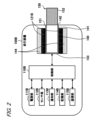
- FIG. 2 is a schematic diagram showing a second configuration example (aerosol generation device 100B) of the aerosol generation device.
- FIG. 3 is a schematic diagram showing a first example of a connection configuration in which the substrate 10 and the power supply unit 111 are electrically connected by conductive members 20a and 20b.
- FIG. 4 is a schematic diagram illustrating electrical wiring of the substrate 10 in the connection configuration of the first example.
- FIG. 5 is a schematic diagram showing a second example of a connection configuration in which the substrate 10 and the power supply unit 111 are electrically connected by conductive members 20a and 20b.
- FIG. 6 is a schematic diagram illustrating electrical wiring of the substrate 10 in the connection configuration of the second example.
- FIG. 7 is a schematic diagram showing a third example of a connection configuration in which the substrate 10 and the power supply unit 111 are electrically connected by conductive members 20a and 20b.
- FIG. 8 is a schematic diagram illustrating electrical wiring of the substrate 10 in a connection configuration according to the third example.
- FIG. 9 is a schematic diagram showing a fourth example of a connection configuration in which the substrate 10 and the power supply unit 111 are electrically connected by conductive members 20a and 20b.
- FIG. 10 is a schematic diagram illustrating electrical wiring of the substrate 10 in the fourth example of the connection configuration.
- FIG. 10 is a schematic diagram illustrating electrical wiring of the substrate 10 in the fourth example of the connection configuration.
- FIG. 11 is a schematic diagram showing a fifth example of a connection configuration in which the boards 10A and 10B and the power supply unit 111 are electrically connected by the conductive members 20a and 20b.
- FIG. 12 is a schematic diagram illustrating electrical wiring of the substrates 10A and 10B in the fifth example of the connection configuration.
- FIG. 13 is a schematic diagram showing a sixth example of a connection configuration in which the boards 10A and 10B and the power supply unit 111 are electrically connected by the conductive members 20a and 20b.
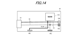
- FIG. 14 is a schematic diagram illustrating electrical wiring of the substrates 10A and 10B in the sixth example of the connection configuration.
- An aerosol generating device is a device that generates an aerosol that is inhaled by a user.
- FIG. 1 is a schematic diagram showing a first configuration example of an aerosol generating device.
- the aerosol generating device 100A of this configuration example includes a power supply unit 110, a cartridge 120, and a flavor imparting cartridge 130.
- the power supply unit 110 includes a power supply section 111A, a sensor section 112A, a notification section 113A, a memory section 114A, a communication section 115A, and a control section 116A.
- the cartridge 120 includes a heating section 121A, a liquid guiding section 122, and a liquid storage section 123.
- the flavor imparting cartridge 130 includes a flavor source 131 and a mouthpiece 124.
- An air flow path 180 is formed in the cartridge 120 and the flavor imparting cartridge 130.
- the power supply unit 111A stores power.
- the power supply unit 111A supplies power to each component of the aerosol generating device 100A under the control of the control unit 116A.
- the power supply unit 111A may be configured, for example, by a rechargeable battery such as a lithium ion secondary battery.
- the sensor unit 112A acquires various information related to the aerosol generating device 100A.
- the sensor unit 112A is configured with a pressure sensor such as a condenser microphone, a flow sensor, or a temperature sensor, and acquires values associated with inhalation by the user.
- the sensor unit 112A is configured with an input device such as a button or switch that accepts information input from the user.
- the notification unit 113A notifies the user of information.
- the information that the notification unit 113A notifies the user includes various information such as the SOC (State Of Charge) indicating the charging state of the power supply unit 111A, the pre-heating time for inhalation, and the period during which inhalation is possible.
- the notification unit 113A is composed of, for example, a light-emitting device that emits light, a display device that displays images, a sound output device that outputs sound, or a vibration device that vibrates.
- the memory unit 114A stores various information for the operation of the aerosol generating device 100A.
- the memory unit 114A is configured, for example, with a non-volatile storage medium such as a flash memory.
- the communication unit 115A is a communication interface capable of performing communication conforming to any wired or wireless communication standard.
- Such communication standards may include, for example, standards using Wi-Fi (registered trademark), Bluetooth (registered trademark), BLE (Bluetooth Low Energy (registered trademark)), NFC (Near Field Communication), or LPWA (Low Power Wide Area).
- the control unit 116A functions as an arithmetic processing unit and control unit, and controls the overall operation of the aerosol generating device 100A in accordance with various programs.
- the control unit 116A is realized by an electronic circuit such as a CPU (Central Processing Unit) or a microprocessor.
- the liquid storage unit 123 stores the aerosol source.
- the aerosol source is atomized to generate an aerosol.
- the aerosol source is, for example, a liquid such as a polyhydric alcohol such as glycerin and propylene glycol, or water.
- the aerosol source may contain a tobacco-derived or non-tobacco-derived flavor component.
- the aerosol generating device 100A is a medical inhaler such as a nebulizer, the aerosol source may contain a medicine.
- the liquid guide section 122 guides and holds the aerosol source, which is a liquid stored in the liquid storage section 123, from the liquid storage section 123.
- the liquid guide section 122 is, for example, a wick formed by twisting a fiber material such as glass fiber or a porous material such as porous ceramic. In this case, the aerosol source stored in the liquid storage section 123 is guided by the capillary effect of the wick.
- the heating unit 121A generates an aerosol by heating the aerosol source and atomizing the aerosol source.
- the heating unit 121A is made of any material such as metal or polyimide in any shape such as a coil, film, or blade.
- the heating unit 121A is configured as a coil wound with a heating resistor such as nichrome or stainless steel, and is wrapped around the liquid guiding unit 122.
- a heating resistor such as nichrome or stainless steel
- power supply to the heating unit 121A may be performed when the sensor unit 112A detects that the user has started inhaling and/or that specific information has been input. Then, power supply to the heating unit 121A may be stopped when the sensor unit 112A detects that the user has stopped inhaling and/or that specific information has been input.
- the heating unit 121A may be configured to generate aerosols by vibration or induction heating.
- the aerosol generating device 100A includes a vibration unit as the heating unit 121A.
- the vibration unit is configured, for example, of a plate-shaped member containing piezoelectric ceramics that functions as an ultrasonic vibrator.
- the vibration unit vibrates, the aerosol source guided to the surface of the vibration unit by the liquid guide unit 122 is atomized by ultrasonic waves generated by the vibration of the vibration unit, and an aerosol is generated.
- the aerosol generating device 100A When the aerosol is generated by induction heating, the aerosol generating device 100A includes a susceptor and an electromagnetic induction source as the heating unit 121A.
- the susceptor is made of a conductive material such as metal, and generates heat by electromagnetic induction.
- the susceptor is disposed close to the liquid guiding unit 122.
- the susceptor is made of a metal conductor and is wound around the liquid guiding unit 122.
- the electromagnetic induction source heats the susceptor by electromagnetic induction.
- the electromagnetic induction source is made of, for example, a coiled conductor, and generates a magnetic field when an alternating current is supplied from the power supply unit 111A. When a magnetic field is generated, an eddy current is generated in the susceptor, generating Joule heat.
- the aerosol source held in the liquid guiding unit 122 is heated and atomized by the Joule heat, and an aerosol is generated.
- the flavor source 131 is a component for imparting flavor components to the aerosol.
- the flavor source 131 may contain tobacco-derived or non-tobacco-derived flavor components.
- the flavor source 131 may be tobacco-derived, such as a processed product in which cut tobacco or tobacco raw materials are molded into granules, sheets, or powder.
- the flavor source 131 may also contain non-tobacco-derived products made from plants other than tobacco (e.g., mint and herbs).
- the flavor source 131 may contain a flavor component such as menthol.
- the flavor source 131 may also be a stick-shaped member.
- the flavor source 131 may contain a drug for the patient to inhale.
- the flavor source 131 is not limited to a solid, and may be, for example, a liquid containing flavor components such as polyhydric alcohols such as glycerin and propylene glycol, and water.
- the flavor source 131 may also be placed inside a container such as a capsule.
- the air flow path 180 is a flow path for air inhaled by the user.
- the air flow path 180 has a tubular structure with an air inlet hole 181, which is an entrance of air into the air flow path 180, and an air outlet hole 182, which is an exit of air from the air flow path 180, at both ends.
- the liquid guide section 122 is arranged on the upstream side (the side closer to the air inlet hole 181), and the flavor source 131 is arranged on the downstream side (the side closer to the air outlet hole 182).
- the air flowing in from the air inlet hole 181 as the user inhales is mixed with the aerosol generated by the heating section 121A, and as shown by the arrow 190, is transported through the flavor source 131 to the air outlet hole 182.
- the flavor components contained in the flavor source 131 are imparted to the aerosol.
- the mouthpiece 124 is a member that is held by the user when inhaling.
- An air outlet hole 182 is arranged in the mouthpiece 124.
- the configuration of the aerosol generating device 100A is not limited to the above, and various configurations such as those exemplified below are possible.
- the aerosol generating device 100A may not include a flavoring cartridge 130.
- the cartridge 120 is provided with a mouthpiece 124.
- the aerosol generating device 100A may further include a flavor source heating unit (not shown) that heats the flavor source 131.
- the flavor source heating unit is, for example, configured in a film shape and arranged to cover the outer periphery of the flavor source 131.
- the flavor source heating unit generates heat when power is supplied from the power supply unit 111A, and heats the flavor source 131 from the outer periphery.
- the flavor source heating unit may be, for example, configured in a blade shape, and may pierce the flavor source 131 to heat the flavor source 131 from the inside.
- the flavor source heating unit may also be configured to heat the flavor source 131 by vibration or induction heating.
- the aerosol generating device 100A may include multiple types of aerosol sources. Multiple types of aerosols generated from the multiple types of aerosol sources may be mixed in the air flow path 180 and undergo a chemical reaction to generate further types of aerosols.
- the means for atomizing the aerosol source is not limited to heating by the heating unit 121A.
- the means for atomizing the aerosol source may be vibration atomization or induction heating.
- FIG. 2 is a schematic diagram showing a second configuration example of the aerosol generating device.
- the aerosol generating device 100B of this configuration example includes a power supply unit 111B, a sensor unit 112B, a notification unit 113B, a memory unit 114B, a communication unit 115B, a control unit 116B, a heating unit 121B, a storage unit 140, and a heat insulating unit 144.
- the power supply unit 110 that stores the power supply unit 111A and the heating unit 121A are separate, but in the aerosol generating device 100B of the second configuration example, the power supply unit 111B and the heating unit 121B are integrated. That is, the aerosol generating device 100B of the second configuration example can also be said to be a power supply unit with a built-in heating unit.
- Each of the power supply unit 111B, the sensor unit 112B, the notification unit 113B, the memory unit 114B, the communication unit 115B, and the control unit 116B is substantially identical to the corresponding components included in the aerosol generating device 100A of the first configuration example.
- the storage section 140 has an internal space 141 and holds the stick-shaped substrate 150 while storing a part of the stick-shaped substrate 150 in the internal space 141.
- the storage section 140 has an opening 142 that connects the internal space 141 to the outside, and stores the stick-shaped substrate 150 inserted into the internal space 141 through the opening 142.
- the storage section 140 is a cylindrical body with the opening 142 and the bottom 143 as the bottom surface, and defines a columnar internal space 141.
- An air flow path that supplies air to the internal space 141 is connected to the storage section 140.
- An air inlet hole which is an air inlet to the air flow path, is arranged, for example, on the side of the aerosol generating device 100.
- An air outlet hole which is an air outlet from the air flow path to the internal space 141, is arranged, for example, on the bottom 143.
- the stick-type substrate 150 includes a substrate portion 151 and a mouthpiece portion 152.
- the substrate portion 151 includes an aerosol source.
- the aerosol source includes a flavor component derived from tobacco or non-tobacco.
- the aerosol source may include a medicine.
- the aerosol source may be, for example, a liquid such as a polyhydric alcohol such as glycerin and propylene glycol, and water, which includes a flavor component derived from tobacco or non-tobacco, or may be a solid which includes a flavor component derived from tobacco or non-tobacco.
- the stick-type substrate 150 When the stick-type substrate 150 is held in the storage portion 140, at least a portion of the substrate portion 151 is stored in the internal space 141, and at least a portion of the mouthpiece portion 152 protrudes from the opening 142.
- the suction mouth portion 152 protruding from the opening 142 in their mouth and inhales air flows into the internal space 141 via an air flow path (not shown) and reaches the user's mouth together with the aerosol generated from the base portion 151.
- the heating section 121B is configured as a film heater with conductive tracks made of a heating resistor having a correlation between electrical resistance and temperature, and is arranged to cover the outer periphery of the storage section 140.
- the heating section 121B generates heat, the substrate section 151 of the stick-shaped substrate 150 is heated from the outer periphery, and an aerosol is generated.
- the heating resistor of the heating section 121B can be the same as the heating resistor of the heating section 121A described above.
- the insulating section 144 prevents heat transfer from the heating section 121B to other components.
- the insulating section 144 is made of a vacuum insulating material or an aerogel insulating material.
- the configuration of the aerosol generating device 100B is not limited to the above, and various configurations such as those exemplified below are possible.
- the heating section 121B may be configured in a blade shape and disposed so as to protrude from the bottom 143 of the storage section 140 into the internal space 141. In that case, the blade-shaped heating section 121B is inserted into the substrate section 151 of the stick-shaped substrate 150 and heats the substrate section 151 of the stick-shaped substrate 150 from the inside. As another example, the heating section 121B may be disposed so as to cover the bottom 143 of the storage section 140. Furthermore, the heating section 121B may be configured as a combination of two or more of a first heating section that covers the outer periphery of the storage section 140, a blade-shaped second heating section, and a third heating section that covers the bottom 143 of the storage section 140.
- the storage unit 140 may include an opening/closing mechanism such as a hinge that opens and closes a portion of the outer shell that forms the internal space 141. The storage unit 140 may then open and close the outer shell to accommodate the stick-shaped substrate 150 inserted into the internal space 141 while clamping it.
- the heating unit 121B may be provided at the clamping location in the storage unit 140, and may heat the stick-shaped substrate 150 while pressing it.
- the means for atomizing the aerosol source is not limited to heating by the heating unit 121B.
- the means for atomizing the aerosol source may be induction heating.
- the aerosol generating device 100B has at least an electromagnetic induction source such as a coil that generates a magnetic field, instead of the heating unit 121B.
- a susceptor that generates heat by induction heating may be provided in the aerosol generating device 100B, or may be included in the stick-shaped substrate 150.
- the aerosol generating device 100B may further include the heating section 121A, the liquid guide section 122, the liquid storage section 123, and the air flow path 180 of the first configuration example, and the air flow path 180 may supply air to the internal space 141.
- the mixed fluid of the aerosol and air generated by the heating section 121A flows into the internal space 141 and is further mixed with the aerosol generated by the heating section 121B, and reaches the user's oral cavity.
- the aerosol generating device 100A and the aerosol generating device 100B described above will be referred to as the "aerosol generating device 100" without distinction.
- the power supply unit 111A and the power supply unit 111B will be referred to as the "power supply unit 111", the sensor unit 112A and the sensor unit 112B as the “sensor unit 112”, the notification unit 113A and the notification unit 113B as the “notification unit 113", the memory unit 114A and the memory unit 114B as the "memory unit 114", the communication unit 115A and the communication unit 115B as the "communication unit 115", the control unit 116A and the control unit 116B as the "control unit 116", and the heating unit 121A and the heating unit 121B as the "heating unit 121".
- the aerosol generating device 100 includes a substrate 10 on which a control unit 116 is mounted, a power supply unit 111, a chassis 50 for holding the power supply unit 111, and conductive members 20a and 20b for connecting the power supply unit 111 and the substrate 10, all housed inside a case 30.
- the sensor unit 112, notification unit 113, storage unit 114, communication unit 115, and heating unit 121 are omitted.
- the substrate 10 includes a positive electrode heating connection portion 12a and a negative electrode heating connection portion 12b (hereinafter also referred to as heating connection portions 12a and 12b) connected to the heating portion 121, a USB (Universal Serial Bus) port 13, a positive electrode power supply connection portion 14a and a negative electrode power supply connection portion 14b (hereinafter also referred to as power supply connection portions 14a and 14b) connected to the power supply portion 111, a discharge circuit 15 that connects the heating connection portions 12a and 12b to the power supply connection portions 14a and 14b, and a charge circuit 16 that connects the USB port 13 to the power supply connection portions 14a and 14b.
- the discharge circuit 15 and the charge circuit 16 are configured to include a portion of common wiring, but the discharge circuit 15 and the charge circuit 16 may be configured entirely from different wiring.
- the heating connections 12a and 12b are connected to heater conductive members (not shown), and the discharge circuit 15 is connected to the heating unit 121 via the heater conductive members.
- the power supply connections 14a and 14b are connected to conductive members 20a and 20b, and the discharge circuit 15 and the charge circuit 16 are connected to the power supply unit 111 via the conductive members 20a and 20b. More specifically, the positive electrode side power supply connection 14a is connected to the positive electrode 111a of the power supply unit 111 via the positive electrode side conductive member 20a, and the negative electrode side power supply connection 14b is connected to the negative electrode 111b of the power supply unit 111 via the negative electrode side conductive member 20b.
- the discharge circuit 15 and the charge circuit 16 are connected to the control unit 116.
- the control unit 116 controls the supply of power from the power supply unit 111 to the heating unit 121 via the conductive members 20a, 20b, the power supply connections 14a, 14b, the discharge circuit 15, the heating connections 12a, 12b, and the heater conductive member.
- the control unit 116 controls the supply of power from the USB port 13 to the power supply unit 111 via the charge circuit 16, the power supply connections 14a, 14b, and the conductive members 20a, 20b.
- the conductive members 20a and 20b are made of a thin conductive metal material, and the conductive metal material is exposed.
- the conductive members 20a and 20b are typically metal foils, such as aluminum foil (foil made of aluminum or an aluminum alloy) or copper foil.
- the conductive members 20a and 20b may also be metal plates, such as metal plates containing nickel or a copper alloy.
- the positive conductive member 20a has a power source side positive electrode contact 21a located at one end fixed to the positive electrode 111a of the power source unit 111, and a board side positive electrode contact 22a located at the other end fixed to the positive electrode side power source connection part 14a.
- the negative conductive member 20b has a negative source side positive electrode contact 21b located at one end fixed to the negative electrode 111b of the power source unit 111, and a board side negative electrode contact 22b located at the other end fixed to the negative electrode side power source connection part 14b.
- Fixing methods such as soldering and welding can be used to fix the power supply side contacts 21a, 21b of the conductive members 20a, 20b to the poles 111a, 111b of the power supply unit 111, and to fix the board side contacts 22a, 22b of the conductive members 20a, 20b to the power supply connection parts 14a, 14b of the board 10.
- the conductive members 20a, 20b swing around the fixed points, the power supply side contacts 21a, 21b and the board side contacts 22a, 22b at both ends. If the conductive members 20a, 20b, which are made of metal foil or the like, swing significantly at this time, the contacts 21a-22b at both ends may come off or the conductive members 20a, 20b may be damaged around the contacts 21a-22b, causing electrical connection to be lost.
- the power supply unit 111 which is heavier than other members in the aerosol generating device, may come off the holding structure of the chassis 50, which may lead to damage to the conductive members 20a, 20b and the contacts 21a-22b.
- the conductive members 20a, 20b of the present disclosure therefore each have a fixed portion 26a, 26b that is fixed to the substrate 10.
- the positive conductive member 20a has a positive fixed portion 26a that is fixed to the substrate 10
- the negative conductive member 20b has a negative fixed portion 26b that is fixed to the substrate 10.
- the fixed portions 26a, 26b are fixed to the substrate 10 at positions different from the substrate contacts 22a, 22b.
- the conductive members 20a and 20b of the present disclosure are provided at the tip of a branch portion 24 that branches off from a main conductive path 23 that connects the power supply side contacts 21a and 21b and the board side contacts 22a and 22b.
- the branch portion 24 is preferably provided at approximately the middle in the longitudinal direction of the conductive members 20a and 20b.
- the fixing portion 26a of the positive side conductive member 20a is fixed to the positive side power supply fixing portion 17a of the board 10 by soldering, welding, etc.
- the fixing portion 26b of the negative side conductive member 20b is fixed to the negative side power supply fixing portion 17b of the board 10 by soldering, welding, etc.
- Fixing the fixing portions 26a and 26b to the board 10 is not limited to soldering or welding, and any fixing method such as fixing with an adhesive, sealing, fixing with tape, etc., or screwing can be used.
- the conductive members 20a, 20b are fixed to the substrate 10 by the fixing portions 26a, 26b, so that even if an impact or the like is applied to the aerosol generating device 100, it is possible to prevent the contacts 21a-22b from peeling off and the conductive members 20a, 20b from being damaged.
- the fixing portions 26a, 26b do not need to be provided at the branch portion 24 branching off from the main conductive path 23, but may be provided at the main conductive path 23 itself, and the main conductive path 23 itself may be fixed. Also, multiple fixing portions 26a, 26b may be provided on one conductive member 20a, 20b.
- the positive power supply fixing portion 17a and the negative power supply fixing portion 17b of the substrate 10 to which the fixing portions 26a, 26b of the conductive members 20a, 20b are fixed may be arranged so as to be electrically connected to the electric circuit provided on the substrate 10, or so as not to be electrically connected to the electric circuit provided on the substrate 10, or so as to be electrically connected to one and not to be electrically connected to the other.
- Arrangement so as not to be electrically connected means, for example, that the power supply fixing portions 17a, 17b are surrounded by insulating resist and cannot exchange power with the discharge circuit 15 and the charge circuit 16.
- the fixing portions 26a, 26b of the conductive members 20a, 20b may be conductive to the circuit formed on the substrate 10, or may be insulated from the circuit formed on the substrate 10.
- the positive power supply connection part 14a and the negative power supply connection part 14b are arranged so as to be conductive to the discharge circuit 15 and the charge circuit 16 provided on the board 10.
- the positive power supply fixing part 17a and the negative power supply fixing part 17b are arranged so as not to be conductive to the discharge circuit 15 and the charge circuit 16 provided on the board 10.
- the fixing parts 26a and 26b of the conductive members 20a and 20b are insulated from the circuits provided on the board 10.
- the positive power supply connection part 14a and the negative power supply connection part 14b are arranged so as to be conductive to the discharge circuit 15 and the charge circuit 16 provided on the board 10.
- the positive power supply fixing part 17a and the negative power supply fixing part 17b are arranged so as to be conductive to the discharge circuit 15 and the charge circuit 16 provided on the board 10.
- the positive power supply connection part 14a and the positive power supply fixing part 17a are integrally formed, and the negative power supply connection part 14b and the negative power supply fixing part 17b are integrally formed. That is, the fixing parts 26a and 26b of the conductive members 20a and 20b are conductive to the discharge circuit 15 and the charge circuit 16 provided on the board 10.
- the fixing units 26a, 26b can be used as contacts different from the power supply connection units 14a, 14b.
- a discharge control unit 116P for controlling discharge and a charge control unit 116Q for controlling charging are separately provided on the board 10.
- the positive power supply connection unit 14a and the negative power supply connection unit 14b are arranged so as to be conductive to the discharge circuit 15 provided on the board 10.
- the positive power supply fixing unit 17a and the negative power supply fixing unit 17b are arranged so as to be conductive to the charge circuit 16 provided on the board 10. That is, the board side contacts 22a, 22b of the conductive members 20a, 20b are conductive to the discharge circuit 15 provided on the board 10, and the fixing units 26a, 26b of the conductive members 20a, 20b are conductive to the charge circuit 16 provided on the board 10.
- power from the power supply unit 111 is supplied to the heating unit 121 via the conductive members 20a, 20b, power supply connection units 14a, 14b, discharge circuit 15, heating connection units 12a, 12b, and heater conductive member.
- power from the USB port 13 is supplied to the power supply unit 111 via the charging circuit 16, power supply fixing units 17a, 17b, and conductive members 20a, 20b.
- a discharge control unit 116P for controlling discharge and a charge control unit 116Q for controlling charging are separately provided on the board 10.
- the positive power supply connection unit 14a and the negative power supply connection unit 14b are arranged so as to be conductive to the discharge circuit 15 provided on the board 10.
- the positive power supply fixing unit 17a and the negative power supply fixing unit 17b only the positive power supply fixing unit 17a is arranged so as to be conductive to the charge circuit 16 provided on the board 10, and the negative power supply fixing unit 17b is arranged so as not to be conductive to the discharge circuit 15 and the charge circuit 16 provided on the board 10. That is, the fixing unit 26a of the positive conductive member 20a is conductive to the circuit provided on the board 10, and the fixing unit 26b of the negative conductive member 20b is insulated from the circuit provided on the board 10.
- power from the power supply unit 111 is supplied to the heating unit 121 via the conductive members 20a, 20b, power supply connections 14a, 14b, discharge circuit 15, heating connections 12a, 12b, and heater conductive member.
- power from the USB port 13 is supplied to the power supply unit 111 via the charging circuit 16, positive power supply fixing unit 17a, negative power supply connection unit 14b, and conductive members 20a, 20b.
- a discharge control unit 116P for controlling discharge is provided on the board 10A
- a charge control unit 116Q for controlling charging is provided on the board 10B.
- the positive power supply connection unit 14a and the negative power supply connection unit 14b are provided on the board 10A and are arranged so as to be conductive to the discharge circuit 15 provided on the board 10A.
- the positive power supply fixing unit 17a and the negative power supply fixing unit 17b are provided on the board 10B and are arranged so as to be conductive to the charge circuit 16 provided on the board 10B.
- the board side contacts 22a and 22b of the conductive members 20a and 20b are conductive to the discharge circuit 15 provided on the board 10A, and the fixing units 26a and 26b of the conductive members 20a and 20b are conductive to the charge circuit 16 provided on the board 10B.
- power from the power supply unit 111 is supplied to the heating unit 121 via the conductive members 20a, 20b, power supply connection units 14a, 14b, discharge circuit 15, heating connection units 12a, 12b, and heater conductive member.
- power from the USB port 13 is supplied to the power supply unit 111 via the charging circuit 16, power supply fixing units 17a, 17b, and conductive members 20a, 20b.
- the fixing parts 26a, 26b of the conductive members 20a, 20b are fixed to the board 10 (10A, 10B), but this is not limiting, and they may be fixed to a member other than the board 10 (10A, 10B), such as the chassis 50 or the case 30.
- the fixing parts 26a and 26b of the conductive members 20a and 20b are fixed to a chassis 50 that holds the power supply unit 111.
- the chassis 50 is made of insulating resin, so that the fixing parts 26a and 26b are insulated.
- the positive power supply connection portion 14a and the negative power supply connection portion 14b are arranged so as to be conductive to the discharge circuit 15 and the charge circuit 16 provided on the substrate 10.
- power from the power supply portion 111 is supplied to the heating portion 121 via the conductive members 20a, 20b, the power supply connection portions 14a, 14b, the discharge circuit 15, the heating connection portions 12a, 12b, and the heater conductive member.
- power from the USB port 13 is supplied to the power supply portion 111 via the charging circuit 16, the power supply connection portions 14a, 14b, and the conductive members 20a, 20b.
- a power source (power source unit 111A, 111B, 111) that supplies power to a heating unit (heating unit 121A, 121B, 121) that heats an aerosol source;
- a control unit (control units 116A, 116B, 116, 116P) that controls the supply of power from the power source to the heating unit;
- a substrate (substrate 10A, 10) on which the control unit is provided;
- Conductive members positive electrode side conductive member 20a, negative electrode side conductive member 20b) that connect the power source and the substrate;
- a power supply unit (power supply unit 110, aerosol generation device 100B, 100) of an aerosol generation device (aerosol generation device 100A, 100B, 100) including a case (case 30) that accommodates the power supply, the control unit, the substrate, and the conductive member,
- the conductive member is A power supply side contact with the power supply (power supply side positive electrode contact 21a, negative source side positive electrode contact 21b), Substrate side contacts with the substrate
- the conductive member is fixed to the substrate, the case, or another member different from the substrate and the case by the fixing portion, so that even if the aerosol generating device is subjected to an impact or the like, it is possible to prevent the contacts from peeling off or the conductive member from being damaged.
- a power supply unit for the aerosol generating device is provided at a branch portion (branch portion 24) branching off from a main conductive path (main conductive path 23) connecting the power supply side contact and the substrate side contact, in the power supply unit of the aerosol generating device.
- the fixing part is a power supply unit of the aerosol generating device, which is fixed to the substrate and insulated from circuits (discharge circuit 15, charge circuit 16) formed on the substrate.
- the fixing portion can prevent electrical defects from occurring in the board.
- the fixing part is a power supply unit of the aerosol generating device, which is fixed to the substrate and is electrically connected to circuits (discharge circuit 15, charge circuit 16) formed on the substrate.
- the fixed part can be used as another contact point.
- a power supply unit for the aerosol generating device is connected to a discharge circuit (discharge circuit 15) connected to the heating unit,
- the fixed part is a power supply unit of the aerosol generating device, which is connected to a charging circuit (charging circuit 16) that is connected to a charging port (USB port 13).
- the board side contacts are used as a discharge circuit and the fixed portion is used as another board side contact connected to a charging circuit, thereby improving the design freedom of the board.
- the other member is a substrate (substrate 10B) different from the substrate
- the fixing portion is a power supply unit of the aerosol generating device, which is fixed to the other substrate.
- the fixed portion is fixed to another substrate, so that one substrate can be made smaller.
- the fixing portion is a power supply unit of the aerosol generating device that is formed on the other substrate and is connected to a charging circuit (charging circuit 16) that leads to a charging port (USB port 13).
- the discharge circuit and the charge circuit can be separated.
- the other member is a chassis (chassis 50) that holds the power supply
- the fixing part is a power supply unit of the aerosol generating device, which is fixed to the chassis.
- the fixed part can be easily fixed by using an insulating and relatively large-volume chassis that holds the power supply as another component.
- the design freedom of the board is improved.
- a power supply unit for the aerosol generating device has a positive electrode side fixing portion (fixing portion 26a) and a negative electrode side fixing portion (fixing portion 26b), the positive electrode side fixed portion and the negative electrode side fixed portion are both fixed to the substrate, A power supply unit for an aerosol generating device, in which at least one of the positive electrode side fixed part and the negative electrode side fixed part is electrically connected to circuits (discharge circuit 15, charge circuit 16) formed on the substrate.
- At least one of the positive and negative fixed parts can be used as a contact point on the other board.
- the negative fixed part may be electrically connected to a ground electrode, and the positive fixed part may be electrically connected to a discharge circuit and/or a charge circuit.
- a power supply unit for the aerosol generating device according to any one of (1) to (9), A power supply unit for an aerosol generating device, wherein the conductive member is made of a plate-shaped conductive metal material, and the conductive metal material is exposed.
- a conductive member in which a plate-shaped conductive metal material is exposed is easily damaged when subjected to impact, but by providing a fixing portion, damage to the conductive member can be prevented.
- a power supply unit for the aerosol generating device according to any one of (1) to (10), The power supply unit of the aerosol generating device, wherein the conductive member is a metal foil.
- a power supply unit for the aerosol generating device according to any one of (1) to (12),
- the fixed portion is provided approximately midway between the power supply side contact and the substrate side contact, in a power supply unit of an aerosol generating device.
- a power supply unit of the aerosol generating device according to any one of (1) to (13);
- the aerosol generating device comprises the heating unit.
- the conductive member is fixed to the substrate, the case, or another member different from the substrate and the case by the fixing portion, so that even if an impact or the like is applied to the aerosol generating device, damage to the conductive member can be suppressed.
Landscapes
- Engineering & Computer Science (AREA)
- Power Engineering (AREA)
- Catching Or Destruction (AREA)
- Charge And Discharge Circuits For Batteries Or The Like (AREA)
Priority Applications (5)
| Application Number | Priority Date | Filing Date | Title |
|---|---|---|---|
| EP23930580.8A EP4691299A1 (en) | 2023-03-30 | 2023-03-30 | Power source unit for aerosol generation device, and aerosol generation device |
| JP2025509537A JPWO2024201943A1 (https=) | 2023-03-30 | 2023-03-30 | |
| PCT/JP2023/013353 WO2024201943A1 (ja) | 2023-03-30 | 2023-03-30 | エアロゾル生成装置の電源ユニット、及びエアロゾル生成装置 |
| KR1020257029144A KR20250137190A (ko) | 2023-03-30 | 2023-03-30 | 에어로졸 생성 장치용 전원 유닛 및 에어로졸 생성 장치 |
| CN202380095370.5A CN120751949A (zh) | 2023-03-30 | 2023-03-30 | 用于气溶胶产生装置的电源单元和气溶胶产生装置 |
Applications Claiming Priority (1)
| Application Number | Priority Date | Filing Date | Title |
|---|---|---|---|
| PCT/JP2023/013353 WO2024201943A1 (ja) | 2023-03-30 | 2023-03-30 | エアロゾル生成装置の電源ユニット、及びエアロゾル生成装置 |
Publications (1)
| Publication Number | Publication Date |
|---|---|
| WO2024201943A1 true WO2024201943A1 (ja) | 2024-10-03 |
Family
ID=92904397
Family Applications (1)
| Application Number | Title | Priority Date | Filing Date |
|---|---|---|---|
| PCT/JP2023/013353 Ceased WO2024201943A1 (ja) | 2023-03-30 | 2023-03-30 | エアロゾル生成装置の電源ユニット、及びエアロゾル生成装置 |
Country Status (5)
| Country | Link |
|---|---|
| EP (1) | EP4691299A1 (https=) |
| JP (1) | JPWO2024201943A1 (https=) |
| KR (1) | KR20250137190A (https=) |
| CN (1) | CN120751949A (https=) |
| WO (1) | WO2024201943A1 (https=) |
Citations (3)
| Publication number | Priority date | Publication date | Assignee | Title |
|---|---|---|---|---|
| JP2017503515A (ja) | 2014-01-20 | 2017-02-02 | キムリー ハイ—テク インコーポレイテッド | バッテリースティック、電子タバコ、およびバッテリースティックの組立方法 |
| CN110547511A (zh) * | 2019-08-01 | 2019-12-10 | 深圳葭南科技有限公司 | 用于更好还原烟油口感的电子烟控制方法及电子烟 |
| WO2023281716A1 (ja) * | 2021-07-08 | 2023-01-12 | 日本たばこ産業株式会社 | エアロゾル生成装置の電源ユニット |
-
2023
- 2023-03-30 WO PCT/JP2023/013353 patent/WO2024201943A1/ja not_active Ceased
- 2023-03-30 JP JP2025509537A patent/JPWO2024201943A1/ja active Pending
- 2023-03-30 CN CN202380095370.5A patent/CN120751949A/zh active Pending
- 2023-03-30 KR KR1020257029144A patent/KR20250137190A/ko active Pending
- 2023-03-30 EP EP23930580.8A patent/EP4691299A1/en active Pending
Patent Citations (3)
| Publication number | Priority date | Publication date | Assignee | Title |
|---|---|---|---|---|
| JP2017503515A (ja) | 2014-01-20 | 2017-02-02 | キムリー ハイ—テク インコーポレイテッド | バッテリースティック、電子タバコ、およびバッテリースティックの組立方法 |
| CN110547511A (zh) * | 2019-08-01 | 2019-12-10 | 深圳葭南科技有限公司 | 用于更好还原烟油口感的电子烟控制方法及电子烟 |
| WO2023281716A1 (ja) * | 2021-07-08 | 2023-01-12 | 日本たばこ産業株式会社 | エアロゾル生成装置の電源ユニット |
Non-Patent Citations (1)
| Title |
|---|
| See also references of EP4691299A1 |
Also Published As
| Publication number | Publication date |
|---|---|
| KR20250137190A (ko) | 2025-09-17 |
| JPWO2024201943A1 (https=) | 2024-10-03 |
| EP4691299A1 (en) | 2026-02-11 |
| CN120751949A (zh) | 2025-10-03 |
Similar Documents
| Publication | Publication Date | Title |
|---|---|---|
| KR20190123553A (ko) | 궐련형 전자담배장치용 히터조립체 및 이를 포함하는 궐련형 전자담배장치 | |
| WO2023002633A1 (ja) | エアロゾル生成システム | |
| EP4635328A1 (en) | Power source unit for aerosol generation device, and aerosol generation device | |
| WO2024201943A1 (ja) | エアロゾル生成装置の電源ユニット、及びエアロゾル生成装置 | |
| EP4635329A1 (en) | Power supply unit for aerosol-generating device, and aerosol-generating device | |
| JP7518295B2 (ja) | エアロゾル生成システム | |
| EP4635331A1 (en) | Power supply unit for aerosol-generating device, and aerosol-generating device | |
| WO2025126401A1 (ja) | エアロゾル生成装置の電源ユニット | |
| WO2025126402A1 (ja) | エアロゾル生成装置の電源ユニット | |
| JP7813386B2 (ja) | エアロゾル生成装置の電源ユニット、及びエアロゾル生成装置 | |
| EP4635330A1 (en) | Power supply unit for aerosol generation device, and aerosol generation device | |
| US20240324685A1 (en) | Power supply unit for aerosol generating device, aerosol generating device, and film heater | |
| WO2025134254A1 (ja) | 吸引装置 | |
| US20240315339A1 (en) | Power source unit for aerosol generating device, and aerosol generating device | |
| JP7595169B2 (ja) | エアロゾル生成システム | |
| JP7518294B2 (ja) | エアロゾル生成システム | |
| WO2025126397A1 (ja) | エアロゾル生成装置 | |
| WO2023275948A1 (ja) | エアロゾル生成システム | |
| WO2024180625A1 (ja) | エアロゾル生成装置の電源ユニット、制御方法、及び制御プログラム | |
| CN120676884A (zh) | 用于气溶胶产生装置的供电单元以及控制方法 | |
| WO2025104791A1 (ja) | 吸引装置 | |
| KR20250107912A (ko) | 흡인 디바이스, 제어 방법 및 프로그램 | |
| CN120076729A (zh) | 气溶胶产生系统 | |
| CN117461897A (zh) | 制造气溶胶供给装置的方法 |
Legal Events
| Date | Code | Title | Description |
|---|---|---|---|
| 121 | Ep: the epo has been informed by wipo that ep was designated in this application |
Ref document number: 23930580 Country of ref document: EP Kind code of ref document: A1 |
|
| ENP | Entry into the national phase |
Ref document number: 2025509537 Country of ref document: JP Kind code of ref document: A |
|
| WWE | Wipo information: entry into national phase |
Ref document number: 2025509537 Country of ref document: JP |
|
| ENP | Entry into the national phase |
Ref document number: 1020257029144 Country of ref document: KR Free format text: ST27 STATUS EVENT CODE: A-0-1-A10-A15-NAP-PA0105 (AS PROVIDED BY THE NATIONAL OFFICE) |
|
| WWE | Wipo information: entry into national phase |
Ref document number: 202380095370.5 Country of ref document: CN |
|
| WWP | Wipo information: published in national office |
Ref document number: 202380095370.5 Country of ref document: CN |
|
| WWE | Wipo information: entry into national phase |
Ref document number: 2023930580 Country of ref document: EP |
|
| NENP | Non-entry into the national phase |
Ref country code: DE |
|
| ENP | Entry into the national phase |
Ref document number: 2023930580 Country of ref document: EP Effective date: 20251030 |
|
| ENP | Entry into the national phase |
Ref document number: 2023930580 Country of ref document: EP Effective date: 20251030 |
|
| ENP | Entry into the national phase |
Ref document number: 2023930580 Country of ref document: EP Effective date: 20251030 |
|
| ENP | Entry into the national phase |
Ref document number: 2023930580 Country of ref document: EP Effective date: 20251030 |
|
| ENP | Entry into the national phase |
Ref document number: 2023930580 Country of ref document: EP Effective date: 20251030 |
|
| ENP | Entry into the national phase |
Ref document number: 2023930580 Country of ref document: EP Effective date: 20251030 |
|
| ENP | Entry into the national phase |
Ref document number: 2023930580 Country of ref document: EP Effective date: 20251030 |
|
| ENP | Entry into the national phase |
Ref document number: 2023930580 Country of ref document: EP Effective date: 20251030 |
|
| WWP | Wipo information: published in national office |
Ref document number: 2023930580 Country of ref document: EP |