WO2024201896A1 - 情報処理方法、情報処理装置、造形方法、造形装置、表示方法及び表示装置 - Google Patents
情報処理方法、情報処理装置、造形方法、造形装置、表示方法及び表示装置 Download PDFInfo
- Publication number
- WO2024201896A1 WO2024201896A1 PCT/JP2023/013192 JP2023013192W WO2024201896A1 WO 2024201896 A1 WO2024201896 A1 WO 2024201896A1 JP 2023013192 W JP2023013192 W JP 2023013192W WO 2024201896 A1 WO2024201896 A1 WO 2024201896A1
- Authority
- WO
- WIPO (PCT)
- Prior art keywords
- support
- modeling
- transition
- dimensional object
- data
- Prior art date
- Legal status (The legal status is an assumption and is not a legal conclusion. Google has not performed a legal analysis and makes no representation as to the accuracy of the status listed.)
- Ceased
Links
Images










Classifications
-
- B—PERFORMING OPERATIONS; TRANSPORTING
- B22—CASTING; POWDER METALLURGY
- B22F—WORKING METALLIC POWDER; MANUFACTURE OF ARTICLES FROM METALLIC POWDER; MAKING METALLIC POWDER; APPARATUS OR DEVICES SPECIALLY ADAPTED FOR METALLIC POWDER
- B22F10/00—Additive manufacturing of workpieces or articles from metallic powder
- B22F10/20—Direct sintering or melting
- B22F10/25—Direct deposition of metal particles, e.g. direct metal deposition [DMD] or laser engineered net shaping [LENS]
-
- B—PERFORMING OPERATIONS; TRANSPORTING
- B22—CASTING; POWDER METALLURGY
- B22F—WORKING METALLIC POWDER; MANUFACTURE OF ARTICLES FROM METALLIC POWDER; MAKING METALLIC POWDER; APPARATUS OR DEVICES SPECIALLY ADAPTED FOR METALLIC POWDER
- B22F10/00—Additive manufacturing of workpieces or articles from metallic powder
- B22F10/40—Structures for supporting workpieces or articles during manufacture and removed afterwards
- B22F10/47—Structures for supporting workpieces or articles during manufacture and removed afterwards characterised by structural features
-
- B—PERFORMING OPERATIONS; TRANSPORTING
- B29—WORKING OF PLASTICS; WORKING OF SUBSTANCES IN A PLASTIC STATE IN GENERAL
- B29C—SHAPING OR JOINING OF PLASTICS; SHAPING OF MATERIAL IN A PLASTIC STATE, NOT OTHERWISE PROVIDED FOR; AFTER-TREATMENT OF THE SHAPED PRODUCTS, e.g. REPAIRING
- B29C64/00—Additive manufacturing, i.e. manufacturing of three-dimensional [3D] objects by additive deposition, additive agglomeration or additive layering, e.g. by 3D printing, stereolithography or selective laser sintering
- B29C64/40—Structures for supporting 3D objects during manufacture and intended to be sacrificed after completion thereof
-
- B—PERFORMING OPERATIONS; TRANSPORTING
- B33—ADDITIVE MANUFACTURING TECHNOLOGY
- B33Y—ADDITIVE MANUFACTURING, i.e. MANUFACTURING OF THREE-DIMENSIONAL [3D] OBJECTS BY ADDITIVE DEPOSITION, ADDITIVE AGGLOMERATION OR ADDITIVE LAYERING, e.g. BY 3D PRINTING, STEREOLITHOGRAPHY OR SELECTIVE LASER SINTERING
- B33Y10/00—Processes of additive manufacturing
Definitions
- the present invention relates to the technical fields of information processing methods, information processing devices, object modeling methods, object modeling devices, display methods, and display devices for modeling objects.
- Patent Document 1 describes an example of a three-dimensional modeling technology known as rapid prototyping, which creates a three-dimensional object (three-dimensional model) directly from CAD data.
- rapid prototyping which creates a three-dimensional object (three-dimensional model) directly from CAD data.
- One of the technical challenges with this type of three-dimensional modeling technology is how to properly process the object.
- an information processing method for generating data related to the formation of a three-dimensional object formed by a DED-type modeling device includes acquiring model data related to the three-dimensional object, generating support shape data related to a support member that supports at least a portion of the three-dimensional object based on the model data, and generating modeling control information for performing modeling by the modeling device based on the model data and the support shape data, wherein generating the support shape data relates to a first support portion formed below at least a portion of the three-dimensional object.
- An information processing method includes generating first support shape data for a first transition section formed between the first support section and at least a portion of the three-dimensional object, generating second support shape data for a second support section different from the first support section formed below at least a portion of the three-dimensional object, and generating second transition shape data for a second transition section formed between the second support section and at least a portion of the three-dimensional object, wherein at least a portion of the first transition section and at least a portion of the second transition section are connected to each other to form at least a portion of a surface.
- an information processing method for generating data relating to the formation of a three-dimensional object formed by a DED-type modeling device comprising the steps of: acquiring object model data relating to the three-dimensional object; generating support shape data relating to a support member that supports at least a portion of the three-dimensional object based on the object model data; and generating modeling control information for performing modeling by the modeling device based on the object model data and the support shape data, and generating the support shape data.
- an information processing method for generating data related to the formation of a three-dimensional object formed by a DED-type modeling device comprising the steps of: acquiring object model data related to the three-dimensional object; generating support shape data related to a support member that supports the three-dimensional object based on the object model data; outputting display data for displaying parts corresponding to the object model data and the support shape data; and generating modeling control information for performing modeling by the modeling device based on the object model data and the support shape data, wherein generating the support shape data includes generating support shape data related to a support part that supports the three-dimensional object, and generating transition shape data related to a transition part provided between the support part and the three-dimensional object, and the display data is data that is capable of distinguishing at least two of an area corresponding to the object model data, an area corresponding to the support shape data, and an area corresponding to the transition shape data from one another.
- an information processing device that generates data related to the modeling of a three-dimensional object formed by a DED-type modeling device has an acquisition unit that acquires model data related to the three-dimensional object, a support shape data generation unit that generates support shape data related to a support member that supports the three-dimensional object based on the acquired model data, and a control unit that generates modeling control information for performing modeling by the modeling device based on the model model data and the support shape data, and the support shape data generation unit acquires model data related to the three-dimensional object,
- An information processing device is provided that generates first support shape data for a first support portion formed below, generates first transition shape data for a first transition portion formed between the first support portion and the three-dimensional object, generates second support shape data for a second support portion different from the first support portion formed below the three-dimensional object, generates second transition shape data for a second transition portion formed between the second support portion and the three-dimensional object, and generates the support shape data such that at least a portion of the first transition portion and
- an information processing device that generates data related to the modeling of a three-dimensional object formed by a DED-type modeling device, the information processing device having an acquisition unit that acquires model data related to the three-dimensional object, a support shape data generation unit that generates support shape data related to a support member that supports the three-dimensional object based on the model data, and a control unit that generates modeling control information for performing modeling by the modeling device based on the model data and the support shape data, the support shape data generation unit generates support shape data related to a support part that is formed below the three-dimensional object, and generates transition shape data related to a transition part that is formed between the support part and the three-dimensional object, and the control unit sets different first modeling conditions under which the modeling device models an area indicated by the model data and second modeling conditions under which the modeling device models an area indicated by at least one of the support part and the transition part.
- an information processing device that generates data related to the modeling of a three-dimensional object formed by a DED-type modeling device, the information processing device having an acquisition unit that acquires model data related to the three-dimensional object, a support shape data generation unit that generates support shape data related to a support member that supports the three-dimensional object based on the model data, a display unit that displays parts corresponding to the model data and the support shape data, respectively, and a control unit that generates modeling control information for performing modeling by the modeling device based on the model data and the support shape data, the support shape data generation unit generates support shape data related to a support part that supports the three-dimensional object, and generates transition shape data related to a transition part provided between the support part and the three-dimensional object, and the display unit displays at least two of the area corresponding to the model data, the area corresponding to the support shape data, and the area corresponding to the transition shape data in a manner that makes them distinguishable from one another.
- a method for forming an object using a DED type forming device including forming a first support portion, forming a first transition portion, forming a second support portion different from the first support portion, forming a second transition portion, and forming the object, the first transition portion being formed between the first support portion and at least a part of the object, the second transition portion being formed between the second support portion and at least a part of the object, at least a part of the first transition portion and at least a part of the second transition portion being connected to each other to form a surface, and at least a part of the object being formed above the surface.
- a method for forming an object using a DED type forming device including forming a first support portion extending in an extension direction, forming a first transition portion on the extension direction side, forming a second support portion extending in the extension direction and different from the first support portion, forming a second transition portion on the extension direction side, and forming the object, wherein at least a portion of the first transition portion and at least a portion of the second transition portion are connected to each other to form a surface, and at least a portion of the object is formed above the surface.
- a modeling method for forming an object using a DED type modeling device including forming a support portion, forming a transition portion, and forming the object, the transition portion being formed between the support portion and at least a part of the object, and a first modeling condition under which the modeling device forms the object and a second modeling condition under which the modeling device forms an area indicated by at least one of the support portion and the transition portion are different from each other.
- a display method for displaying data relating to the formation of a three-dimensional object formed by a DED-type modeling device comprising: displaying an object model relating to the three-dimensional object; and displaying a portion corresponding to a support shape relating to a support member supporting the three-dimensional object, the support shape including a support shape relating to a support section supporting the three-dimensional object and a transition shape relating to a transition section provided between the support section and the three-dimensional object, and at least two of the area corresponding to the object model, the area corresponding to the support shape, and the area corresponding to the transition shape are displayed in a manner that makes them distinguishable from one another.
- a processing device that forms a three-dimensional object includes an irradiation optical system capable of irradiating a processing beam, a material supply unit capable of supplying a modeling material to a portion where a molten pool is formed by irradiation of the processing beam or a material supply unit capable of supplying a modeling material in a direction intersecting the direction in which the processing beam is irradiated, and includes an acquisition unit that acquires model data related to the three-dimensional object, a support shape data generation unit that generates support shape data related to a support member that supports at least a part of the three-dimensional object based on the acquired model data, and a control unit that generates modeling control information for performing modeling by the processing device based on the model data and the support shape data.
- the support shape data generation unit generates first support shape data for a first support portion formed below at least a portion of the three-dimensional object, generates first transition shape data for a first transition portion formed between the first support portion and at least a portion of the three-dimensional object, generates second support shape data for a second support portion different from the first support portion formed below at least a portion of the three-dimensional object, generates second transition shape data for a second transition portion formed between the second support portion and at least a portion of the three-dimensional object, and at least a portion of the first transition portion and at least a portion of the second transition portion are connected to each other to form at least a portion of a surface.
- a processing device for forming a three-dimensional object includes an irradiation optical system capable of irradiating a processing beam, a material supply unit capable of supplying a modeling material to a portion where a molten pool is formed by irradiation of the processing beam or capable of supplying a modeling material in a direction intersecting the direction in which the processing beam is irradiated, and an acquisition unit for acquiring model data related to the three-dimensional object, a support shape data generation unit for generating support shape data related to a support member that supports at least a portion of the three-dimensional object based on the model data, and a processing device for forming a three-dimensional object based on the model data and the support shape data.
- the support shape data generation unit generates support shape data for a support part to be modeled below at least a portion of the three-dimensional object, and generates transition shape data for a transition part to be modeled between the support part and at least a portion of the three-dimensional object
- the control unit includes a first modeling condition under which the processing device models an area indicated by the model data of the object, and a second modeling condition under which the processing device models an area indicated by at least one of the support part and the transition part, and the first modeling condition and the second modeling condition are made different from each other.
- a processing device for forming a three-dimensional object includes an irradiation optical system capable of irradiating a processing beam, a material supply unit capable of supplying a modeling material to a portion where a molten pool is formed by irradiation of the processing beam or capable of supplying a modeling material in a direction intersecting the direction in which the processing beam is irradiated, and includes an acquisition unit for acquiring model data relating to the three-dimensional object, a support shape data generation unit for generating support shape data relating to a support member that supports the three-dimensional object based on the model data, and a display unit for displaying portions corresponding to the model data and the support shape data.
- the support shape data generation unit generates support shape data for a support portion to be modeled below at least a portion of the three-dimensional object, and generates transition shape data for a transition portion to be modeled between the support portion and at least a portion of the three-dimensional object
- the display unit is a display device that displays at least two of the area corresponding to the model data, the area corresponding to the support shape data, and the area corresponding to the transition shape data in a manner that makes them distinguishable from one another.
- an information processing method for generating data relating to a three-dimensional object comprising: acquiring object model data relating to the three-dimensional object; and generating support shape data relating to a support member relating to the three-dimensional object based on the object model data, wherein generating the support shape data includes generating first support shape data relating to a first support portion formed below the three-dimensional object; generating first transition shape data relating to a first transition portion formed between the first support portion and the three-dimensional object; generating second support shape data relating to a second support portion different from the first support portion formed below the three-dimensional object; and generating second transition shape data relating to a second transition portion formed between the second support portion and the three-dimensional object, wherein at least a portion of the first transition portion and at least a portion of the second transition portion are connected to each other.
- an information processing method for generating data relating to a three-dimensional object comprising: acquiring object model data relating to the three-dimensional object; and generating support shape data relating to a support member relating to the three-dimensional object based on the object model data, wherein generating the support shape data includes generating first support shape data relating to a first support portion formed below the three-dimensional object; and generating second support shape data relating to a second support portion different from the first support portion formed below the three-dimensional object, wherein an upper cross-sectional area of the first support shape is larger than a lower cross-sectional area, an upper cross-sectional area of the second support shape is larger than a lower cross-sectional area, and the first support shape and the second support shape are connected to each other.
- an information processing method for generating data related to a three-dimensional object comprising: acquiring object model data related to the three-dimensional object; generating support shape data related to a support member related to the three-dimensional object based on the object model data; and generating modeling control information for performing modeling based on the object model data and the support shape data, wherein generating the support shape data includes generating support shape data related to a support part to be modeled below the three-dimensional object, and generating transition shape data related to a transition part to be modeled between the support part and the three-dimensional object, the modeling control information including first modeling conditions for modeling an area indicated by the object model data and second modeling conditions for modeling an area indicated by at least one of the support part and the transition part, and the first modeling conditions and the second modeling conditions are different from each other.
- an information processing method for generating data relating to a three-dimensional object comprising: acquiring object model data relating to the three-dimensional object; generating support shape data relating to a support member relating to the three-dimensional object based on the object model data; and outputting display data for displaying portions corresponding to the object model data and the support shape data, respectively, wherein generating the support shape data includes generating support shape data relating to a support portion of the three-dimensional object, and generating transition shape data relating to a transition portion provided between the support portion and the three-dimensional object, and the display data is data that is capable of distinguishing at least two of an area corresponding to the object model data, an area corresponding to the support shape data, and an area corresponding to the transition shape data from one another.
- a method for forming an object using a modeling device including forming a first support portion, forming a first transition portion, forming a second support portion different from the first support portion, and forming a second transition portion, the first transition portion being formed between the first support portion and at least a part of the object, the second transition portion being formed between the second support portion and at least a part of the object, at least a part of the first transition portion and at least a part of the second transition portion being connected to each other to form a surface, and at least a part of the object being formed above the surface.
- a method for forming an object using a modeling device including forming a first support portion extending in an extension direction, forming a first transition portion on the extension direction side, forming a second support portion extending in the extension direction and different from the first support portion, forming a second transition portion on the extension direction side, and forming the object, wherein at least a portion of the first transition portion and at least a portion of the second transition portion are connected to each other to form a surface, and at least a portion of the object is formed above the surface.
- a modeling method for modeling an object using a modeling device including modeling a support portion, modeling a transition portion, and modeling the object, the transition portion being formed between the support portion and at least a portion of the object, and a first modeling condition under which the modeling device models the object and a second modeling condition under which the modeling device models an area indicated by at least one of the support portion and the transition portion are different from each other.
- a display method for displaying data relating to the formation of a three-dimensional object formed by a modeling device comprising: displaying an object model relating to the three-dimensional object; and displaying a portion corresponding to a support shape relating to a support member relating to the three-dimensional object, the support shape including a support shape relating to a support part relating to the three-dimensional object and a transition shape relating to a transition part provided between the support part and the three-dimensional object, and in which at least two of the area corresponding to the object model, the area corresponding to the support shape, and the area corresponding to the transition shape are displayed in a manner that makes them distinguishable from one another.
- an information processing method for generating data relating to the formation of a three-dimensional object formed by a DED-type modeling device comprising the steps of: acquiring model data relating to the three-dimensional object; generating support shape data relating to a support member that supports the formation of at least a portion of the three-dimensional object based on the model data; and generating modeling control information for performing modeling by the modeling device based on the model data and the support shape data, wherein generating the support shape data includes:
- An information processing method is provided that includes generating first support shape data for a first transition section formed between the first support section and at least a portion of the three-dimensional object, generating first transition shape data for a first transition section formed between the first support section and at least a portion of the three-dimensional object, generating second support shape data for a second support section different from the first support section formed between at least a portion of the three-dimensional object and the object, and generating second transition shape data for a second transition section formed between the second
- an information processing method for generating data related to the formation of a three-dimensional object formed by a DED-type modeling device comprising: acquiring object model data related to the three-dimensional object; generating support shape data related to a support member that supports at least a portion of the three-dimensional object based on the object model data; and generating modeling control information for performing modeling by the modeling device based on the object model data and the support shape data, wherein generating the support shape data includes generating first transition shape data related to a first transition portion formed below at least a portion of the three-dimensional object, and generating second transition shape data related to a second transition portion formed below at least a portion of the three-dimensional object, and wherein at least a portion of the first transition portion and at least a portion of the second transition portion are connected to each other to form at least a portion of a surface.
- FIG. 1 is a cross-sectional view showing the structure of a machining system according to the present embodiment.
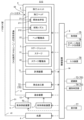
- FIG. 2 is a system configuration diagram showing the configuration of the machining system of this embodiment.
- FIG. 3 is a perspective view showing the structure of the irradiation optical system.
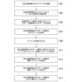
- FIG. 4 is a flowchart corresponding to a series of processing algorithms of the information processing apparatus of this embodiment.
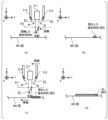
- Each of (a) to (d) of Figure 5 is a cross-sectional view showing a state in which a certain area on a workpiece is irradiated with processing light and a modeling material is supplied.
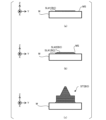
- Each of (a) to (c) of FIG. 6 is a cross-sectional view showing a process for forming a three-dimensional structure.
- FIG. 1 is a cross-sectional view showing the structure of a machining system according to the present embodiment.
- FIG. 2 is a system configuration diagram showing the configuration of the machining system of this embodiment.
- FIG. 3 is a perspective view showing
- FIG. 7 is a side view showing an example of a three-dimensional structure.
- FIG. 8 is a schematic explanatory diagram showing the problem in the conventional technology.
- Each of (a) and (b) of Figure 9 is a schematic explanatory diagram showing the modeling method of the present embodiment.
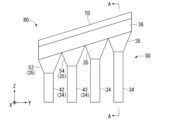
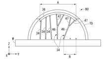
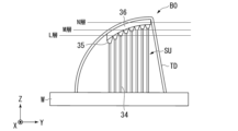
- FIG. 10 is a side view showing an example of a three-dimensional structure and a support member.
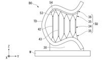
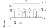
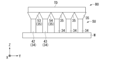
- FIG. 11 is a partial side view showing an example of a three-dimensional structure and a support member.
- FIG. 12 is a partial side view showing an example of a three-dimensional structure and a support member.
- FIG. 13 is a partial side view showing an example of a three-dimensional structure and a support member.
- FIG. 10 is a side view showing an example of a three-dimensional structure and a support member.
- FIG. 11 is a partial side view showing an example of a three-dimensional structure and a support member.
- FIG. 12 is a partial side view showing an example of a three-dimensional structure and
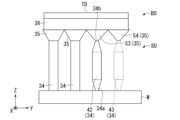
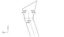
- FIG. 14 is a partial side view showing an example of a three-dimensional structure and a support member.
- FIG. 15 is a partial side view showing an example of a three-dimensional structure and a support member.
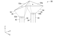
- FIG. 16 is a perspective view illustrating an example of the configuration of a support member.
- FIG. 17 is a perspective view showing an example of the configuration of a support member.
- FIG. 18 is a perspective view showing an example of the configuration of a support member.
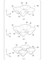
- Each of (a) to (c) of Figure 19 is a perspective view showing an example of the configuration of a support member.
- FIG. 20 is a perspective view illustrating an example of the configuration of a support member.
- FIG. 21 is a side view showing an example of a three-dimensional structure and a support member.
- FIG. 21 is a side view showing an example of a three-dimensional structure and a support member.
- FIG 22 is a perspective view showing an example of the configuration of a support member.
- FIG. 23 is a cross-sectional view showing an example of the configuration of a support member.
- FIG. 24 is a cross-sectional view showing an example of the configuration of a support member.
- FIG. 25 is a partial side view showing an example of a three-dimensional structure and a support member.
- FIGS. 26A to 26C show slice data for the L layer, the M layer and the N layer in FIG. 25, respectively.
- Each of (a) to (d) of Figure 27 is a cross-sectional view showing a process of forming a three-dimensional structure by irradiating a certain area on a modeling surface with processing light and supplying modeling material.
- an information processing method an information processing device, a modeling method, a modeling device, a display method, and a display device
- a processing system SYS that performs additive processing on a workpiece W, which is an example of an object, to form a modeled object BO on the workpiece W.
- a processing system SYS modeling device
- DED Directed Energy Deposition
- SYS modeling device
- powdered metal is sprayed near the focus of a laser beam, and the melted and liquid metal is attached to the processing target, or the metal is melted in a molten pool formed by the laser beam and then cooled and solidified. In this way, a modeled object BO is formed on the workpiece W.
- the DED welding method may also be called direct metal deposition, laser metal deposition, laser cladding, laser engineered net shaping, direct light fabrication, laser consolidation, shape deposition manufacturing, wire-feed laser deposition, gas-through-wire, laser powder fusion, laser metal forming, selective laser powder remelting, laser direct casting, laser powder deposition, laser additive manufacturing, and laser rapid forming.
- XYZ Cartesian coordinate system defined by mutually orthogonal X-, Y-, and Z-axes.
- the X- and Y-axes are horizontal (i.e., a specific direction within a horizontal plane) and the Z-axis is vertical (i.e., a direction perpendicular to the horizontal plane, essentially an up-down direction).
- the directions of rotation around the X-, Y-, and Z-axes (in other words, tilt directions) are referred to as the ⁇ X direction, ⁇ Y direction, and ⁇ Z direction, respectively.
- the Z-axis direction may be the direction of gravity.
- the XY plane may be horizontal.
- Fig. 1 is a cross-sectional view showing an example of the structure of the machining system SYS of the present embodiment.
- Fig. 2 is a system configuration diagram showing an example of the configuration of the machining system SYS of the present embodiment.
- the processing system SYS is capable of forming (in other words, forming) the object BO.
- the object BO may refer to any object formed by the processing system SYS.
- the object BO is typically a three-dimensional object having a size in all three-dimensional directions (i.e., a solid object, in other words, an object having a size in the X-axis direction, the Y-axis direction, and the Z-axis direction).
- An example of the object BO is a three-dimensional structure ST (see FIG. 6(c)) having a desired three-dimensional shape.
- An example of the object BO is a part of the three-dimensional structure ST.
- An example of the object BO is any object formed in the process of forming the three-dimensional structure ST.
- an example of the object BO is the structural layer SL.
- An example of the object BO is a part of the structural layer SL.
- An example of the object BO is any object that is formed in the process of forming the structural layer SL.
- the object BO is not limited to the objects exemplified here.
- the processing system SYS can form the object BO on the workpiece W, which serves as a base (e.g., a base material) for forming the object BO. In other words, the processing system SYS performs forming on the workpiece W.
- the processing system SYS can form the object BO by performing additional processing on the workpiece W. If the workpiece W is the stage 31 described below, the processing system SYS can form the object BO on the stage 31. If the workpiece W is a placed object, which is an object placed on the stage 31, the processing system SYS can form the object BO on the placed object. In this case, the processing system SYS may form the object BO integrated with the placed object.
- the operation of forming the object BO integrated with the placed object is equivalent to the operation of adding a new structure to the placed object.
- the existing structure may be, for example, an object with a missing part (e.g., an item in need of repair).
- the processing system SYS may form a structure BO that can be separated from the placed object.
- the placed object on the stage 31 may be another structure BO (i.e., an existing structure (primary object, first object)) formed by the processing system SYS.
- FIG. 1 shows an example in which the workpiece W is an existing structure held by the stage 31. The following description will also be given using an example in which the workpiece W is an existing structure held by the stage 31.
- object BO refers to the object formed on the workpiece W as described above.
- object BO includes a "three-dimensional object TD" having a desired predetermined shape, and a "support member SU” for supporting the formation of this three-dimensional object TD.
- object BO when there is no need to distinguish between the three-dimensional object TD and the support member SU, both may be collectively referred to as object BO.
- the processing system SYS is capable of forming the object BO using the DED method.
- the processing system SYS can be said to be a 3D printer that forms objects using additive manufacturing technology.
- additive manufacturing technology is also called rapid prototyping, rapid manufacturing, or additive manufacturing.
- the processing system SYS processes the modeling material M using the processing light EL, which is a processing beam, to form a model BO.
- the modeling material M is a material that can be melted by irradiation with processing light EL of a predetermined intensity or higher.
- at least one of a metallic material and a resinous material can be used as the modeling material M.
- other materials other than the metallic material and the resinous material may be used as the modeling material M.
- the modeling material M is a powdered material.
- the modeling material M is a powder.
- the powder may contain a granular material in addition to the powdered material.
- the modeling material M may contain, for example, a powder with a particle size within the range of 90 micrometers ⁇ 40 micrometers.
- the average particle size of the powder constituting the modeling material M may be, for example, 75 micrometers or less, may be within the range of 10 micrometers to 25 micrometers, or may be another size.
- the average particle size of the powder can be about 200, 190, 180, 170, 160, 150, 140, 130, 120, 110, 100, 95, 90, 85, 80, 75, 70, 65, 60, 55, 50, 45, 40, 35, 30, 25, 20, 15, 10 micrometers, or less.
- the modeling material M can be a material other than a powder.
- at least one of a wire-shaped modeling material and a gas-shaped modeling material may be used as the modeling material M. The above values are merely examples, and the present invention is not limited thereto.
- a model BO is formed on a workpiece W by supplying a modeling material M to a molten pool MP formed by a laser beam.
- powdered metal is sprayed near the focus (focused position) of a processing beam focused by a condenser lens 2113 (see FIG. 3).
- the powdered metal is then melted and liquefied by the irradiation of the processing beam. If a processing object is located near the focus, the liquefied metal adheres to the processing object, cools, and solidifies. This focal point becomes a pen tip, so to speak, and can draw "lines with thickness" one after another on the surface of the processing object.
- the desired shape is formed by appropriately moving one of the processing object and the processing head 21 (processing light EL or material nozzle 212 described later, etc.) relative to the other based on CAD data.
- a method may be used in which powdered metal is sprayed near the focus of a laser beam, and the melted and liquefied metal is allowed to adhere to the processing object.
- a method of attaching molten modeling material M to the workpiece and a method of pouring modeling material M into the molten pool MP may be combined, for example, in a ratio of 7:3.
- the type of workpiece W may be the same as the type of modeling material M.
- the workpiece W may be the same type (or a different type) of metal as modeling material M.
- the workpiece W may be the same type (or a different type) of resin as modeling material M.
- the processing system SYS includes a material supply device 1, a processing device 2, a stage device 3, a light source 4, a gas supply device 5, a housing 6, a measuring device 71, a removal processing unit 72, and a control device (control unit) 8, as shown in Figures 1 and 2. At least a portion of each of the processing device 2, the stage device 3, and the measuring device 71 is contained within the chamber space 63IN inside the housing 6. In this case, the processing system SYS may perform additional processing in the chamber space 63IN. Note that at least one of the processing device 2 and the stage device 3 does not have to be contained within the chamber space 63IN inside the housing 6.
- the material supplying device 1 supplies the modeling material M to the processing device 2. Specifically, the material supplying device 1 and the processing device 2 (particularly the material nozzle 212 described later) are connected via a supply pipe 11. The material supplying device 1 supplies the modeling material M to the processing device 2 via the supply pipe 11. At this time, the material supplying device 1 may supply a desired amount of modeling material M according to the required amount so that the amount of modeling material M required per unit time for the processing device 2 to perform additional processing is supplied to the processing device 2.
- the material supplying device 1 is an example of a "material supply unit".
- the processing device 2 forms a model BO using the modeling material M supplied from the material supply device 1.
- the processing device 2 includes a processing head 21 and a head drive system 22.
- the processing head 21 further includes an irradiation optical system 211 and a material nozzle (i.e., a supply system or supply device that supplies the modeling material M) 212.
- the processing head 21 and the head drive system 22 are housed in the chamber space 63IN. However, at least a part of the processing head 21 and/or the head drive system 22 may be disposed in the external space 64OUT, which is the space outside the housing 6.
- the external space 64OUT may be a space that an operator of the processing system SYS can enter.
- the irradiation optical system 211 is an optical system (e.g., a focusing optical system) for emitting the processing light EL from the emission unit 213. Specifically, the irradiation optical system 211 is optically connected to the light source 4 that emits the processing light EL via a light transmission member 41 such as an optical fiber or a light pipe. In the example shown in FIG. 2, the modeling system SYS has one light source 4, and the irradiation optical system 211 is optically connected to the light source 4 via the light transmission member 41. The irradiation optical system 211 emits the processing light EL propagated from the light source 4 via the light transmission member 41. Note that the configuration may have, for example, multiple irradiation optical systems 211.
- the irradiation optical system 211 irradiates the processing light EL downward (i.e., toward the -Z side) from the irradiation optical system 211.
- a stage 31 is disposed below the irradiation optical system 211. When a workpiece W is placed on the stage 31, the irradiation optical system 211 irradiates the emitted processing light EL to the workpiece W (particularly, the surface of the workpiece W).
- the irradiation optical system 211 can irradiate the processing light EL to a target irradiation area (target irradiation position) EA that is set on or near the workpiece W as an area to be irradiated (typically, focused) with the processing light EL. Furthermore, under the control of the control device 8, the state of the irradiation optical system 211 can be switched between a state in which the processing light EL is irradiated to the target irradiation area EA and a state in which the processing light EL is not irradiated to the target irradiation area EA.
- the direction of the processing light EL emitted from the irradiation optical system 211 is not limited to directly downward (i.e., coinciding with the -Z axis direction), and may be, for example, a direction inclined by a predetermined angle with respect to the Z axis.
- the irradiation optical system 211 may include a state control optical system 2111, a galvanometer mirror 2112, and a focusing lens 2113.
- the state control optical system 2111 is an optical system capable of controlling the state of the processing light EL emitted by the irradiation optical system 211.
- the state control optical system 2111 may include a focus control optical system capable of controlling (e.g., changing) the focusing position of the processing light EL (i.e., the position where the processing light EL is most converged).
- the state control optical system 2111 may control the focusing position of the processing light EL, for example, by changing the distance (positional relationship) with the focusing lens 2113 in the traveling direction of the processing light EL, changing the distance (positional relationship) with the material nozzle 212, or changing the distance (positional relationship) with the powder supply position by the material nozzle 212, etc.
- the focus control optical system may include, for example, multiple lenses arranged along the traveling direction of the processing light EL. In this case, the focusing position of the processing light EL may be changed by moving at least one of the multiple lenses along its optical axis direction.
- the state control optical system 2111 may also include an intensity control optical system capable of controlling (e.g., changing) the intensity of the processing light EL.
- the intensity control optical system may include a shutter capable of blocking at least a portion of the processing light EL, a filter capable of reducing light, or the like.
- the irradiation optical system does not have to include the state control optical system 2111.
- the processing light EL that has passed through the state control optical system 2111 is incident on the galvanometer mirror 2112.
- the galvanometer mirror 2112 deflects the processing light EL (changing the deflection angle (emission angle) of the processing light EL) to change the emission direction of the processing light EL from the galvanometer mirror 2112.
- the galvanometer mirror 2112 may be referred to as a deflection member or a deflection optical system.
- the target irradiation area EA onto which the processing light EL is irradiated moves on the surface of the workpiece W (more specifically, the printing surface MS described below on which additional processing is performed).
- the irradiation position onto which the processing light EL is irradiated moves on the printing surface MS.
- the processing light EL moves on the printing surface MS.
- the galvanometer mirror 2112 includes, for example, an X-scanning mirror 2112X and a Y-scanning mirror 2112Y. Each of the X-scanning mirror 2112X and the Y-scanning mirror 2112Y may be referred to as a galvanometer mirror 2112. Each of the X-scanning mirror 2112X and the Y-scanning mirror 2112Y is an inclination angle variable mirror that can change the angle with respect to the optical path of the processing light EL incident on each mirror.
- the X-scanning mirror 2112X reflects the processing light EL toward the Y-scanning mirror 2112Y.
- the X-scanning mirror 2112X can swing or rotate around a rotation axis along the Y axis.
- the swing or rotation of the X-scanning mirror 2112X causes the processing light EL to scan the printing surface MS along the X-axis direction.
- the swing or rotation of the X-scanning mirror 2112X causes the target irradiation area EA to move along the X-axis direction on the printing surface MS.
- the Y-scanning mirror 2112Y reflects the processing light EL toward the f ⁇ lens 2113.
- the Y-scanning mirror 2112Y can swing or rotate around a rotation axis along the X-axis.
- the swing or rotation of the Y-scanning mirror 2112Y causes the processing light EL to scan the printing surface MS along the Y-axis direction.
- the swing or rotation of the Y-scanning mirror 2112Y moves the target irradiation area EA along the Y-axis direction on the printing surface MS.
- the X-scanning mirror 2112X and the Y-scanning mirror 2112Y it is possible to move the target irradiation area EA two-dimensionally on the printing surface MS.
- the galvanometer mirror 2112 allows the processing light EL to scan within the modeling shot area ESA.
- the irradiation optical system 211 can irradiate the processing light EL to the modeling shot area ESA that is determined based on the irradiation optical system 211.
- the target irradiation area EA can be moved within the modeling shot area ESA that is determined based on the irradiation optical system 211. Note that, for example, when there are multiple irradiation optical systems 211, the modeling shot areas ESA in each irradiation optical system 211 may coincide, or the modeling shot areas ESA may be partially different.
- the direction of the processing light EL emitted from each of the multiple irradiation optical systems 211 may be inclined at a predetermined angle with respect to the Z axis, and the optical axes of the respective irradiation optical systems 211 on the modeling surface MS side (typically the optical axes of the focusing optical systems (f ⁇ lenses 2113) of the irradiation optical systems 211) may intersect with each other on the modeling surface MS or on a surface nearby it.
- the target irradiation area EA can be moved along the X-axis direction within the modeling shot area ESA by the X-scanning mirror 2112X. Furthermore, the target irradiation area EA can be moved along the Y-axis direction within the modeling shot area ESA by the Y-scanning mirror 2112Y. Furthermore, as described above, the focusing position of the processing light EL can be changed along the Z-axis direction by the state control optical system 2111.
- the irradiation optical system 211 can move the irradiation position of the processing light EL within the modeling shot area ESA (specifically, the position of the target irradiation area EA in each of the X-axis and Y-axis directions, and the focusing position in the Z-axis direction) along each of the X-axis, Y-axis, and Z-axis directions. More specifically, the target irradiation area EA can be moved two-dimensionally on the XY plane by the X-scanning mirror 2112X and the Y-scanning mirror 2112Y, and the focusing position can be moved in the Z-axis direction.
- the irradiation optical system 211 can set the irradiation position of the processing light EL to any position in the three-dimensional space on the modeling shot area ESA side of the irradiation optical system 211.
- the irradiation optical system 211 can move the processing light EL along the X-axis direction, Y-axis direction, and Z-axis direction within the modeling shot area ESA.
- the printing shot area ESA indicates the maximum area (in other words, the maximum range) in which the processing head 21 can perform additional processing using the processing light EL when the positional relationship between the irradiation optical system 211 and the printing surface MS is fixed.
- the printing shot area ESA may coincide with the maximum scanning range of the processing light EL deflected by the galvanometer mirror 2112 when the positional relationship between the irradiation optical system 211 and the printing surface MS is fixed.
- the printing shot area ESA may be an area determined based on the effective movable range of the galvanometer mirror 2112.
- the printing shot area ESA may be an area determined based on the optical effective range of the condenser lens 2113 by irradiating the processing light EL to the printing surface MS via the condenser lens 2113.
- the printing shot area ESA may be an area included in the area determined based on the effective movable range of the galvanometer mirror 2112 or the optical effective range of the condenser lens 2113.
- the printing shot area ESA may be defined in a plane perpendicular to the optical axis AX of the irradiation optical system 211.
- the optical axis AX of the irradiation optical system 211 is an axis along the traveling direction of the processing light EL irradiated onto the printing surface MS.
- the optical axis AX of the irradiation optical system 211 may be the optical axis of the condenser lens 2113.
- the optical axis AX of the irradiation optical system 211 may be different from the optical axis of the condenser lens 2113.
- the optical axis AX is an axis along the Z axis.
- the processing head 21 may perform additional processing within a modeling unit area BSA set within the modeling shot area ESA.
- the modeling unit areas BSA in each irradiation optical system 211 may be the same, or each modeling unit area BSA may be partially different (i.e., each modeling unit area BSA may partially overlap), or each modeling unit area BSA may be different (i.e., each modeling unit area BSA may not overlap).
- the shaping unit area BSA indicates the area (in other words, the range) where the processing head 21 actually performs additional processing using the processing light EL when the positional relationship between the irradiation optical system 211 and the printing surface MS is fixed. In other words, the processing head 21 may perform additional processing on the entire surface of the shaping unit area BSA.
- the shaping unit area BSA indicates the area (in other words, the range) where the processing head 21 actually scans with the processing light EL when the positional relationship between the irradiation optical system 211 and the printing surface MS is fixed.
- the shaping unit area BSA indicates the area where the target irradiation area EA actually moves when the positional relationship between the irradiation optical system 211 and the printing surface MS is fixed.
- Such a shaping unit area BSA coincides with at least a part of the shaping shot area ESA.
- the shaping unit area BSA may coincide with the shaping shot area ESA.
- the shaping unit area BSA may coincide with a part of the shaping shot area ESA.
- the shaping unit area BSA may be smaller than the shaping shot area ESA.
- the smaller the amount of rotation of the galvanometer mirror 2112 i.e., the smaller the rotation angle of the galvanometer mirror 2112
- the smaller the area scanned by the processing light EL and therefore the smaller the modeling unit area BSA.
- the irradiation optical system 211 may set a modeling unit area BSA of a desired size within the modeling shot area ESA by controlling the amount of rotation of the galvanometer mirror 2112 (more specifically, the amount of rotation of the X-scanning mirror 2112X and the Y-scanning mirror 2112Y) under the control of the control device 8.
- the shape of the shaping unit area BSA is rectangular.
- the shape of the shaping unit area BSA may be a shape other than rectangular (for example, circular, elliptical, or polygonal).
- the corners of the rectangle may be rounded.
- the size of the shaping unit area BSA in the X-axis direction and the Y-axis direction may be several millimeters.
- the size of the shaping unit area BSA is not limited to several millimeters.
- the size of the shaping unit area BSA can be approximately 10, 9, 8, 7, 6, 5, 4, 3, 2, 1 millimeter, or less. The same can be said about the shape of the shaping shot area ESA.
- the above values are merely examples, and the present invention is not limited thereto.
- the printing unit areas BSA are scanned with the processing light EL by the galvanometer mirror 2112. Therefore, compared to when the processing light EL is irradiated onto the printing surface MS without using the galvanometer mirror 2112, the distribution of the amount of heat transferred from the processing light EL to the printing unit area BSA is less likely to vary within the printing unit area BSA. In other words, the amount of heat transferred from the processing light EL to the printing unit area BSA can be made uniform. As a result, the printing system SYS can print the object BO on the printing surface MS with relatively high printing accuracy.
- the modeling system SYS does not have to irradiate the processing light EL onto the modeling surface MS in units of modeling unit areas BSA.
- the modeling system SYS may irradiate the processing light EL onto the modeling surface MS without using the galvanometer mirror 2112.
- the target irradiation area EA may move on the modeling surface MS in conjunction with the movement of at least one of the processing head 21 and the stage 31.
- the focusing lens 2113 is an optical system for emitting the processing light EL from the galvanometer mirror 2112 toward the printing surface MS.
- the focusing lens 2113 is an optical element that can focus the processing light EL from the galvanometer mirror 2112 on a focusing surface.
- the focusing lens 2113 may be referred to as a focusing member.
- the focusing surface of the focusing lens 2113 may be set, for example, in the vicinity of the printing surface MS.
- the irradiation optical system 211 may be equipped with a focusing member (focusing optical system) different from the focusing lens 2113.
- processing head 21 includes a part of the irradiation optical system 211, another part of the irradiation optical system 211 may be disposed outside the processing head 21.
- the material nozzle 212 is formed with a supply outlet 214.
- the material nozzle 212 supplies (e.g., ejects, jets, spouts, or sprays) the modeling material M from the supply outlet 214.
- the material nozzle 212 may be referred to as a material supply member.
- the material nozzle 212 is physically connected to the material supply device 1, which is a supply source of the modeling material M, via the supply pipe 11 and the mixer 12.
- the material nozzle 212 supplies the modeling material M supplied from the material supply device 1 via the supply pipe 11 and the mixer 12.
- the material nozzle 212 may pressure-feed the modeling material M supplied from the material supply device 1 via the supply pipe 11.
- the modeling material M from the material supply device 1 and the gas for conveyance may be mixed in the mixer 12 and then pressure-feed to the material nozzle 212 via the supply pipe 11.
- the material nozzle 212 supplies the modeling material M together with the gas for transport.
- a purge gas supplied from the gas supply device 5 is used as the gas for transport.
- a gas supplied from a gas supply device other than the gas supply device 5 may be used as the gas for transport.
- the material nozzle 212 is depicted in FIG. 1 as a tube, the shape of the material nozzle 212 is not limited to this shape. Also, in FIG.
- a pair of material nozzles 212 are provided on both sides of the irradiation optical system 211, but a single material nozzle 212 may be provided.
- the material nozzle 212 supplies the modeling material M toward the target or target area in the chamber space 63IN.
- the material nozzle 212 supplies the modeling material M from the material nozzle 212 downward (i.e., toward the -Z side).
- the stage 31 is disposed below the material nozzle 212. When the workpiece W is mounted on the stage 31, the material nozzle 212 supplies the modeling material M toward the workpiece W or the vicinity of the workpiece W.
- the direction of travel of the modeling material M supplied from the material nozzle 212 is inclined at a predetermined angle (an acute angle, for example) with respect to the Z-axis direction, but it may also be on the -Z side (i.e., directly below).
- the inclination of the material nozzle 212 is not limited to the above and can be set arbitrarily.
- the material nozzle 212 supplies the modeling material M near the focal point of the processing light EL from the irradiation optical system 211.
- the material nozzle 212 supplies the modeling material M to the target irradiation area EA to which the irradiation optical system 211 irradiates the processing light EL.
- the material nozzle 212 and the irradiation optical system 211 are aligned so that the target supply area MA, which is set on or near the workpiece W as the area to which the material nozzle 212 supplies the modeling material M, coincides with (or at least partially overlaps with) the target irradiation area EA.
- the material nozzle 212 may deposit the modeling material M melted by the processing light EL emitted from the irradiation optical system 211 onto the workpiece W.
- the area to which the molten modeling material M is deposited may be called a molten pool MP.
- the target supply area MA and the target irradiation area EA do not have to be the same size.
- the target supply area MA may be larger than the target irradiation area EA.
- the target supply area MA may also be smaller than the target irradiation area EA.
- the processing system SYS uses the irradiation optical system 211 provided in the processing head 21 to irradiate the workpiece W with the processing light EL from the light source 4, and also uses the material nozzle 212 provided in the processing head 21 to form the object BO.
- an apparatus including the processing head 21 i.e., the irradiation optical system 211 and the material nozzle 212 that is primarily used to form the object BO, and at least one of the material supply device 1 and the light source 4 may be referred to as the processing device 2.
- the head drive system 22 moves the processing head 21.
- the head drive system 22 moves the processing head 21, for example, within the chamber space 63IN.
- the head drive system 22 moves the processing head 21 along at least one of the X-axis, Y-axis, and Z-axis.
- each of the target irradiation area EA and the target supply area MA moves along at least one of the X-axis and Y-axis to any position on the workpiece W or within the chamber space 63IN.
- the head drive system 22 may move the processing head 21 along at least one of the rotation directions of the ⁇ X direction, the ⁇ Y direction, and the ⁇ Z direction in addition to or instead of at least one of the X-axis, Y-axis, and Z-axis.
- the head drive system 22 may rotate the processing head 21 around at least one of the X-axis, Y-axis, and Z-axis.
- the head drive system 22 may change the attitude of the processing head 21 around at least one of the X-axis, Y-axis, and Z-axis.
- the head drive system 22 includes, for example, an actuator such as a motor.
- the head drive system 22 moves the processing head 21, the relative positions of the processing head 21 and the stage 31 and the workpiece W supported by the stage 31 change.
- the relative positions of the irradiation optical system 211 and the material nozzle 212 (supply outlet 214) and the stage 31 and the workpiece W change.
- the head drive system 22 may function as a position change device for changing the relative positional relationship between the irradiation optical system 211 and the material nozzle 212 (supply outlet 214) and the stage 31 and the workpiece W.
- the head drive system 22 may function as a position change device for changing the relative positional relationship between the target irradiation area EA and the stage 31 and the workpiece W. Furthermore, when the relative positions of the processing head 21, the stage 31, and the workpiece W change, the target irradiation area EA and the target supply area MA move relative to the workpiece W. Therefore, the head drive system 22 may function as a moving device that moves the target irradiation area EA and the target supply area MA relative to the workpiece W.
- the stage device 3 includes a stage 31.
- a workpiece W which is an object, is placed on the stage 31.
- the workpiece W is placed on a placement surface 311, which is at least a part of the upper surface of the stage 31.
- the stage 31 may be capable of holding the workpiece W placed on the stage 31.
- the stage 31 may be equipped with at least one of a mechanical chuck, an electrostatic chuck, and a vacuum suction chuck, etc., in order to hold the workpiece W.
- the stage 31 may not be capable of holding the workpiece W placed on the stage 31.
- the workpiece W may be placed on the stage 31 in a clampless manner.
- the irradiation optical system 211 described above emits the processing light EL during at least a part of the period during which the workpiece W is placed on the stage 31. Furthermore, the material nozzle 212 described above supplies the modeling material M during at least a part of the period during which the workpiece W is placed on the stage 31.
- the stage device 3 further includes a stage drive system 32.
- the stage drive system 32 moves the stage 31.
- the stage drive system 32 moves the stage 31 along at least one of the X-axis, Y-axis, Z-axis, ⁇ X-direction, ⁇ Y-direction, and ⁇ Z-direction.
- the stage drive system 32 may function as a position changing device for changing the relative positional relationship between the processing head 21 and the stage 31 and the workpiece W.
- the target irradiation area EA and the target supply area MA move relative to the workpiece W.
- the light source 4 emits, for example, at least one of infrared light, visible light, and ultraviolet light as the processing light EL. However, other types of light may be used as the processing light EL.
- the processing light EL may include multiple pulsed lights (i.e., multiple pulse beams).
- the processing light EL may be laser light.
- the light source 4 may include a laser light source (for example, a semiconductor laser such as a laser diode (LD: Laser Diode).
- the laser light source may be a fiber laser, a CO2 laser, a YAG laser, an excimer laser, etc.
- the processing light EL does not have to be laser light.
- the light source 4 may include any light source (for example, at least one of an LED (Light Emitting Diode) and a discharge lamp, etc.).
- the gas supply device 5 is a supply source of purge gas for purging the chamber space 63IN.
- the purge gas includes an inert gas. Examples of the inert gas include nitrogen gas or argon gas.
- the gas supply device 5 is connected to the chamber space 63IN via a supply port 62 formed in the partition member 61 of the housing 6 and a supply pipe 51 connecting the gas supply device 5 and the supply port 62.
- the gas supply device 5 supplies purge gas to the chamber space 63IN via the supply pipe 51 and the supply port 62.
- the chamber space 63IN becomes a space purged by the purge gas.
- the purge gas supplied to the chamber space 63IN may be exhausted from an exhaust port (not shown) formed in the partition member 61.
- the gas supply device 5 may be a cylinder storing an inert gas such as nitrogen gas or argon gas.
- the gas supply device 5 may be a nitrogen gas generator that generates nitrogen gas using the air as a raw material.
- the gas supply device 5 may supply the purge gas to the mixing device 12 to which the modeling material M from the material supply device 1 is supplied in addition to the chamber space 63IN.
- the gas supply device 5 may be connected to the mixing device 12 via a supply pipe 52 connecting the gas supply device 5 and the mixing device 12.
- the gas supply device 5 supplies the purge gas to the mixing device 12 via the supply pipe 52.
- the modeling material M from the material supply device 1 may be supplied (specifically, pressure-fed) through the supply pipe 11 toward the material nozzle 212 by the purge gas supplied from the gas supply device 5 via the supply pipe 52.
- the gas supply device 5 may be connected to the material nozzle 212 via the supply pipe 52, the mixing device 12, and the supply pipe 11.
- the material nozzle 212 supplies the modeling material M from the supply outlet 214 together with the purge gas for pressure-fed the modeling material M.
- the housing 6 is a housing device that houses at least a part of each of the processing device 2, the stage device 3, and the measuring device 71 in a chamber space 63IN, which is the internal space of the housing 6.
- the housing 6 includes a partition member 61 that defines the chamber space 63IN.
- the partition member 61 is a member that separates the chamber space 63IN from the external space 64OUT of the housing 6.
- the partition member 61 faces the chamber space 63IN via its inner wall 611, and faces the external space 64OUT via its outer wall 612. In this case, the space surrounded by the partition member 61 (specifically, the space surrounded by the inner wall 611 of the partition member 61) becomes the chamber space 63IN.
- the partition member 61 may be provided with a door that can be opened and closed.
- This door may be opened when the workpiece W is placed on the stage 31.
- the door may be opened when the workpiece W and/or the molded object BO is removed from the stage 31.
- the door may be closed during processing (i.e., during additional processing or joining processing).
- An observation window (not shown) for visually observing the chamber space 63IN from the external space 64OUT of the housing 6 may be provided in the partition member 61.
- the measuring device 71 is disposed in the chamber space 63IN.
- the measuring device 71 can measure at least a part of the object BO placed on the stage 31 in the chamber space 63IN.
- the measuring device 71 includes a detector such as a camera that detects parameters related to the measurement target, a sensor that acquires information related to the parameters of the measurement target, and/or a sensor that acquires an image of the measurement target.
- the measuring device 71 can measure the object BO formed on the workpiece W by the processing light EL.
- the measurement result of the measuring device 71 includes information related to at least the shape of the three-dimensional object TD, which is the desired shape, and the shape of the support member SU (see FIG.
- the measuring device 71 may function as a device that can acquire information related to the shapes of the three-dimensional object TD and the support member SU (hereinafter, sometimes collectively referred to as the object BO).
- the measuring device 71 may be a device that performs coaxial measurement, such as a TTL (Through The Lens) that performs observation from the same axis as the optical axis of processing.
- TTL Through The Lens
- a semi-transparent mirror may be installed between the condenser lens 2113 and the Y-scanning mirror 2112Y in FIG. 3, and the molded object BO may be observed from the side.
- the measuring device 71 may function as a device capable of acquiring information regarding the supply amount of the modeling material M, information regarding the size and shape of the modeling material M melted by irradiation with the processing light EL (e.g., physical parameters, shape parameters), and information regarding the size and shape of the molten pool MP.
- the measurement results of the measuring device 71 may also include information regarding the shape of the modeled object BO.
- the control device 8 may control modeling by the processing system SYS based on the shape information of the modeled object BO, molten pool MP, etc. measured by the measuring device 71.
- the measurement results of the measuring device 71 are output to the control device 8.
- the control device 8 may change the intensity of the processing light EL, the supply amount of the modeling material M, etc. based on the measurement results of the measuring device 71.
- the measuring device 71 may be any type of measuring device as long as it is capable of measuring the object BO.
- the measuring device 71 may be a measuring device capable of optically measuring the object BO.
- the measuring device 71 may be a measuring device capable of measuring the object BO by contacting the object BO.
- the measuring device 71 may be a measuring device capable of measuring the object BO without contacting the object BO.
- Examples of measuring devices capable of optically measuring the object BO without contacting the object BO include an imaging device, radar, and laser device capable of capturing an image of the object BO.
- the measuring device 71 is an imaging device will be explained. In this case, the measuring device 71 captures an image of the object BO to generate an image (captured image) in which the object BO is captured.
- the captured image of the object BO is output to the control device 8 as the measurement result of the measuring device 71.
- the chamber space 63IN may contain unwanted materials, including a portion of the forming material M supplied from the material nozzle 212 that was not used to form the object BO. Furthermore, the chamber space 63IN may contain unwanted materials, including metal vapor (so-called fumes) that has evaporated due to the irradiation of the processing light EL. If such unwanted materials adhere to the measuring device 71 placed in the chamber space 63IN, the measuring device 71 may not be able to properly measure the molten pool MP. For this reason, the measuring device 71 may be placed in the chamber space 63IN while being housed in a housing that prevents unwanted materials from adhering to the measuring device 71.
- the removal processing unit 72 is disposed in the chamber space 63IN.
- the removal processing unit 72 can remove at least a part of the support member SU from the three-dimensional object TD of the object BO placed on the stage 31 in the chamber space 63IN.
- the removal processing unit 72 includes a tool for performing cutting, grinding, etc. on the three-dimensional object TD and the support member SU formed integrally by modeling to remove (remove) the support member SU from the three-dimensional object TD.
- the removal processing unit 72 can remove at least a part of the part of the object BO processed (modeled) by the processing device 2 that corresponds to the support member SU.
- the removal processing unit 72 is not limited to a contact type removal processing device that removes and processes the workpiece (three-dimensional object TD or support member SU) using a tool or the like, and may be a non-contact type removal processing device such as an optical processing device that removes and processes the workpiece using laser light or the like.
- the removal processing unit 72 may be a device that dissolves the workpiece by supplying the workpiece with a liquid that dissolves the workpiece.
- the removal processing unit 72 is connected to the control device 8.
- the removal processing unit 72 is controlled to determine the portion of the formed object BO to be removed based on a signal output from the control device 8, and to remove the determined portion. While a portion of the formed object BO is being removed by the removal processing unit 72, for example, the measuring device 71 may continue to measure the formed object BO, or may measure the formed object BO intermittently while a portion of the formed object BO is being removed by the removal processing unit 72. In this case, the measurement results by the measuring device 71 may be fed back and reflected in the processing (removal) in the removal processing unit 72.
- a recognition unit 73 that recognizes the shape of the formed object BO in a state in which the three-dimensional formed object TD and the support member SU are integrated after the formation is completed may be connected to the removal processing unit 72.
- the recognition unit 73 may be part of the control device 8.
- an identification and determination unit 74 may be connected to the removal processing unit 72, which distinguishes the shape of the object BO recognized by the recognition unit 73 into a portion corresponding to the three-dimensional object TD and a portion corresponding to the support member SU.
- the identification and determination unit 74 may be part of the control device 8.
- the control device 8 controls the operation of the processing system SYS.
- the control device 8 may control the processing device 2 (for example, at least one of the processing head 21 and the head drive system 22) included in the processing system SYS.
- the control device 8 may control the material supply device 1 included in the processing system SYS.
- the control device 8 may control the light source 4 included in the processing system SYS.
- the control device 8 may control at least one of the processing device 2, the material supply device 1, and the light source 4 to form the object BO.
- the control device 8 may control the forming by at least one of the processing device 2, the material supply device 1, and the light source 4.
- the control device 8 may control at least one of the processing device 2, the material supply device 1, and the light source 4 so that the processing device 2 performs the desired forming (specifically, forms the desired object BO) using the forming material M supplied from the material supply device 1 and the processing light EL supplied from the light source 4.
- the control device 8 is an example of a "control unit".
- the control device 8 may control the operation of the modeling system SYS based on modeling condition information that specifies the modeling conditions of the object BO by the modeling system SYS (e.g., at least one of the following: the size, shape, weight, and material of the object BO; the size, shape, weight, and material of the support member SU; whether or not the support member SU is provided; whether or not the support member SU is provided; information on the power and spot diameter of the laser when modeling the object BO; information on the size and shape of the modeling material M; the above examples may be referred to as modeling-related parameters).
- the modeling condition information may be input to the control device 8 via an input device 78 provided in the modeling system SYS.
- the input device 78 may include an operating device (e.g., at least one of a keyboard, a mouse, and a touch panel) that can be operated by an operator (user) of the modeling system SYS to input the modeling condition information.
- the input device 78 may include a communication device that can transmit and receive modeling condition information to and from a device external to the modeling system SYS.
- the input device 78 may include a recording medium reading device capable of reading the modeling condition information recorded on a recording medium that can be externally attached to the modeling system SYS.
- the control device 8 may include, for example, an arithmetic device and a storage device.
- the arithmetic device may include, for example, at least one of a CPU (Central Processing Unit) and a GPU (Graphics Processing Unit).
- the storage device may include, for example, a memory.
- the control device 8 functions as a device that controls the operation of the machining system SYS by the arithmetic device executing a computer program.
- This computer program is a computer program for making the arithmetic device perform (i.e., execute) the operation to be performed by the control device 8, which will be described later.
- this computer program is a computer program for making the control device 8 function so as to make the machining system SYS perform the operation to be described later.
- the computer program executed by the arithmetic device may be recorded in a storage device (i.e., a recording medium) included in the control device 8, or may be recorded in any storage medium (e.g., a hard disk or a semiconductor memory) built into the control device 8 or that can be externally attached to the control device 8.
- the arithmetic device may download the computer program to be executed from a device external to the control device 8 via a network interface.
- the control device 8 may control the emission mode of the processing light EL by the irradiation optical system 211.
- the emission mode may include, for example, at least one of the intensity of the processing light EL, the emission timing of the processing light EL, and the emission direction of the processing light EL.
- the emission mode may include, for example, at least one of the emission time of the pulsed light, the emission cycle of the pulsed light, and the ratio of the length of the emission time of the pulsed light to the emission cycle of the pulsed light (so-called duty ratio).
- the emission mode of the processing light EL by the irradiation optical system 211 is mainly determined by the emission mode of the processing light EL by the light source 4.
- controlling the emission mode of the processing light EL by the irradiation optical system 211 may be considered equivalent to controlling the emission mode of the processing light EL by the irradiation optical system 211.
- the control device 8 may control the emission mode of the processing light EL by the irradiation optical system 211 by controlling the emission mode of the processing light EL by the light source 4.
- the control device 8 may control the movement mode of the processing head 21 by the head drive system 22.
- the control device 8 may control the movement mode of the stage 31 by the stage drive system 32.
- the movement mode may include, for example, at least one of the movement amount, the movement speed, the movement direction, and the movement timing.
- control device 8 may control the supply mode of the modeling material M by the material nozzle 212.
- the supply mode may include, for example, at least one of the supply amount (particularly, the supply amount per unit time) and the supply timing.
- the supply mode of the modeling material M by the material nozzle 212 is mainly determined by the supply mode of the modeling material M by the material supply device 1. For this reason, controlling the supply mode of the modeling material M by the material supply device 1 may be considered equivalent to controlling the supply mode of the modeling material M by the material nozzle 212.
- the control device 8 may control the supply mode of the modeling material M by the material nozzle 212 by controlling the supply mode of the modeling material M by the material supply device 1.
- control device 8 may generate data related to the formation of the three-dimensional object TD formed by the DED processing system SYS.
- the control device 8 may control the operation of the processing system SYS based on the generated data.
- the control device 8 may include an acquisition unit 75 that acquires object model data related to the three-dimensional object TD.
- the control device 8 may include a support shape data generation unit 76 that generates support shape data related to a support member SU that supports at least a part of the three-dimensional object TD based on the object model data acquired by the acquisition unit 75.
- the control device 8 may include a display unit 77 that displays parts corresponding to the generated object model data and the support shape data.
- the acquisition unit 75, the support shape data generation unit 76, and the display unit 77 may be configured separately from the control device 8 and electrically connected to the control device 8.
- the control device 8 may generate formation control information for performing formation by the processing device 2 based on the acquired object model data and the generated support shape data. The operation of controlling the processing system SYS based on the object model data and support shape data will be described in detail later.
- the control device 8 does not have to be provided inside the processing system SYS.
- the control device 8 may be provided outside the processing system SYS as a server or the like.
- the control device 8 and the processing system SYS may be connected by a wired and/or wireless network (or a data bus and/or a communication line).
- a wired network for example, a network using a serial bus type interface represented by at least one of IEEE1394, RS-232x, RS-422, RS-423, RS-485, and USB may be used.
- a network using a parallel bus type interface may be used.
- a network using an interface compliant with Ethernet (registered trademark) represented by at least one of 10BASE-T, 100BASE-TX, and 1000BASE-T may be used.
- a network using radio waves may be used.
- An example of a network using radio waves is a network conforming to IEEE802.1x (for example, at least one of a wireless LAN and Bluetooth (registered trademark)).
- a network using infrared rays may be used as a wireless network.
- a network using optical communication may be used as a wireless network.
- the control device 8 and the processing system SYS may be configured to be able to transmit and receive various information via the network.
- the control device 8 may be able to transmit information such as commands and control parameters to the processing system SYS via the network.
- the processing system SYS may include a receiving device that receives information such as commands and control parameters from the control device 8 via the network.
- the processing system SYS may include a transmitting device (i.e., an output device that outputs information to the control device 8) that transmits information such as commands and control parameters to the control device 8 via the network.
- a first control device that performs a part of the processing performed by the control device 8 may be provided inside the processing system SYS, while a second control device that performs another part of the processing performed by the control device 8 may be provided outside the processing system SYS.
- the recording medium for recording the computer program executed by the control device 8 may be at least one of CD-ROM, CD-R, CD-RW, flexible disk, MO, DVD-ROM, DVD-RAM, DVD-R, DVD+R, DVDRW, DVD+RW, optical disks such as Blu-ray (registered trademark), magnetic media such as magnetic tape, magneto-optical disk, semiconductor memory such as USB memory, and any other medium capable of storing a program.
- the recording medium may include a device capable of recording a computer program (for example, a general-purpose device or a dedicated device in which a computer program is implemented in a state in which it can be executed in at least one of the forms of software and firmware).
- each process or function included in the computer program may be realized by a logical processing block realized in the control device 8 by the control device 8 (i.e., a computer) executing the computer program, or may be realized by hardware such as a predetermined gate array (FPGA, ASIC) provided in the control device 8, or may be realized in a form in which a logical processing block and a partial hardware module that realizes some elements of the hardware are mixed.
- a logical processing block realized in the control device 8 by the control device 8 (i.e., a computer) executing the computer program
- hardware such as a predetermined gate array (FPGA, ASIC) provided in the control device 8
- FPGA predetermined gate array
- the machining system SYS performs a modeling operation (i.e., modeling of the object BO) for forming the object BO by performing additional processing on the workpiece W. Furthermore, as shown in FIG. 4, at the start of the modeling period, the machining system SYS performs a model data acquisition operation (corresponding to step S01 in FIG. 4) for acquiring object model data related to the three-dimensional object TD.
- the model data acquisition operation may be performed by transmitting and receiving model data from a part of the machining system SYS or a control device different from the control device 8.
- the model data acquisition operation may be started by a user's input, or a button may be displayed on the display unit 77 to support the user's input. This button may be a button that instructs the machining system SYS to start the model data acquisition operation or suggests to the user that a support member SU is to be added.
- the model data acquisition operation may also be started at the timing when the software is started by the user.
- the modeling period may be a period from when the control device acquires the model data of the object to when the modeling operation is completed.
- a period during which the processing system SYS is in a standby state in which it does not perform modeling and until the control device acquires the model data of the object may be referred to as a modeling preparation period.
- the processing system SYS may acquire model data of the three-dimensional object TD. Furthermore, the processing system SYS performs a support shape data generating operation (corresponding to steps S03 to S07 in FIG. 4 ) for generating support shape data of the support member SU that supports at least a part of the three-dimensional object TD based on the acquired model data of the object. Furthermore, the processing system SYS performs a modeling control information generating operation (corresponding to steps S11 to S13 in FIG. 4 ) for generating modeling control information for performing modeling by the processing device 2 based on the model data of the object and the support shape data. Furthermore, the processing system SYS performs a display operation (corresponding to step S17 in FIG.
- the processing system SYS performs a support member removing operation to remove the formed support member SU. Therefore, hereinafter, the forming operation, the model data obtaining operation, the support shape data generating operation, the forming control information generating operation, the display operation, and the support member removing operation will be described in this order.
- the processing system SYS forms a three-dimensional structure ST on the workpiece W based on three-dimensional model data (e.g., CAD (Computer Aided Design) data) of the three-dimensional structure ST to be formed.
- Measurement data of a solid object measured by at least one of a measuring device (e.g., measuring device 71) provided in the processing system SYS and a three-dimensional shape measuring device provided separately from the processing system SYS may be used as the three-dimensional model data.
- the processing system SYS sequentially forms, for example, a plurality of layered partial structures (hereinafter referred to as "structural layers") SL arranged along the Z-axis direction.
- the structural layer SL (and further, an object constituting a part of the structural layer SL that is formed in the process of forming the structural layer SL) also corresponds to the formed object BO.
- the processing system SYS sequentially models multiple structural layers SL obtained by slicing the three-dimensional structure ST along the Z-axis direction, one by one.
- a three-dimensional structure ST is formed, which is a layered structure in which multiple structural layers SL are stacked.
- each structural layer SL will be described with reference to (a) to (d) of FIG. 5.
- the processing system SYS moves at least one of the processing head 21 and the stage 31 so that the target irradiation area EA is set in a desired area on the printing surface MS corresponding to the surface of the workpiece W or the surface of the already formed structural layer SL.
- the processing system SYS irradiates the processing light EL from the irradiation optical system 211 to the target irradiation area EA.
- the focus position (i.e., the light collection position) of the processing light EL may be located in the vicinity of the printing surface MS.
- the focus position of the processing light EL may coincide with the printing surface MS.
- the processing system SYS supplies the printing material M from the material nozzle 212. As a result, as shown in FIG. 5(a), the supplied printing material M melts and adheres to the printing surface MS.
- the irradiation optical system 211 uses the galvanometer mirror 2112 to move the target irradiation area EA within the printing unit area BSA. That is, the irradiation optical system 211 uses the galvanometer mirror 2112 to scan the printing unit area BSA with the processing light EL.
- the processing light EL is no longer irradiated onto the portion where the printing material M is attached as the target irradiation area EA moves
- the printing material M attached to the printing surface MS is cooled and solidified (i.e., solidified).
- the molten printing material M is again attached to a location different from the location where the printing material M was previously attached.
- a printing object BO composed of the solidified printing material M is deposited on the printing surface MS.
- the printing system SYS may move at least one of the processing head 21 and the stage 31 so that the printing unit area BSA moves on the printing surface MS. In other words, the printing system SYS may move the target irradiation area EA within the printing unit area BSA and move the printing unit area BSA on the printing surface MS in parallel.
- the printing system SYS does not have to move the processing head 21 and the stage 31 so that the printing unit area BSA does not move on the printing surface MS.
- the printing system SYS may move at least one of the processing head 21 and the stage 31 so that the printing unit area BSA is set in another area on the printing surface MS.
- the printing system SYS may move at least one of the processing head 21 and the stage 31 so that the printing unit area BSA moves on the printing surface MS.
- the modeling system SYS may move at least one of the processing head 21 and the stage 31 so that the area on the modeling surface MS where the modeling unit area BSA has already been set (i.e., the area where the additional processing has already been performed) and the area on the modeling surface MS where the modeling unit area BSA has newly been set (i.e., the area where the additional processing will be performed from now on) are adjacent to each other.
- the modeling system SYS may move at least one of the processing head 21 and the stage 31 so that the area on the modeling surface MS where the modeling unit area BSA has already been set and the area on the modeling surface MS where the modeling unit area BSA has newly been set do not overlap.
- the modeling system SYS may move at least one of the processing head 21 and the stage 31 so that the area on the modeling surface MS where the modeling unit area BSA has already been set and the area on the modeling surface MS where the modeling unit area BSA has newly been set partially overlap each other.
- the processing system SYS repeats a series of printing processes including irradiation of the processing light EL, supply of the printing material M, melting of the supplied printing material M, and solidification of the molten printing material M, while moving the processing head 21 along at least one of the X-axis direction and the Y-axis direction relative to the printing surface MS, as shown in FIG. 5(c).
- the processing system SYS repeats a scanning operation in which the processing head 21 moves along at least one of the X-axis direction and the Y-axis direction relative to the printing surface MS while irradiating the printing surface MS with the processing light EL at a desired timing, and a step operation in which the processing head 21 moves along the other of the X-axis direction and the Y-axis direction relative to the printing surface MS without irradiating the printing surface MS with the processing light EL.
- the processing system SYS irradiates the processing light EL to the area on the printing surface MS where the object BO is to be printed, while not irradiating the processing light EL to the area on the printing surface MS where the object BO is not to be printed. That is, the processing system SYS irradiates the processing light EL onto the printing surface MS at a timing according to the distribution of the area where the object BO is to be printed, while moving the target irradiation area EA along a predetermined movement trajectory on the printing surface MS.
- the processing system SYS repeats a scanning operation of moving the target irradiation area EA along either the X-axis direction or the Y-axis direction relative to the printing surface MS while irradiating the target irradiation area EA with the processing light EL at a desired timing, and a step operation of moving the target irradiation area EA along the other of the X-axis direction or the Y-axis direction relative to the printing surface MS without irradiating the target irradiation area EA with the processing light EL.
- the molten printing material M also moves on the printing surface MS along a movement trajectory according to the movement trajectory of the target irradiation area EA.
- the printing material M melts in the area on the printing surface MS where the processing light EL is irradiated among the areas along the movement trajectory of the target irradiation area EA, and adheres to the printing surface MS.
- a structural layer SL corresponding to the object BO which is an aggregate of the melted and then solidified modeling material M, is formed on the modeling surface MS.
- a structural layer SL corresponding to the aggregate of the objects BO formed on the modeling surface MS in a pattern corresponding to the movement trajectory of the modeling unit area BSA i.e., a structural layer SL having a shape corresponding to the movement trajectory of the modeling unit area BSA in a planar view
- the processing system SYS may irradiate the target irradiation area EA with the processing light EL and stop the supply of the modeling material M.
- the movement path (in other words, the movement trajectory) of the shaping unit area BSA may be called a processing path (in other words, a tool path).
- Processing path information processing path parameters
- the processing path information may include information (e.g., coordinate information) related to a plurality of positions where at least one of the shaping unit areas BSA is set sequentially. In this case, each position where at least one of the shaping unit areas BSA is set may be called a unit processing path.
- the control device 8 may move at least one of the processing head 21 and the stage 31 so that the shaping unit area BSA moves along the movement path specified by the processing path information. Since additional processing (i.e., shaping) is performed within the shaping unit area BSA, the processing path may mean the path along which the processing device 2 performs shaping on the shaping surface MS.
- the printing condition information may include printing size information regarding the size of the printing unit area BSA.
- the printing size information may include information regarding the size of the printing unit area BSA in the X-axis direction.
- the printing size information may include information regarding the size of the printing unit area BSA in the Y-axis direction.
- the processing path information includes information regarding each position (i.e., unit processing path) where the printing unit area BSA is set
- the printing size information may include information regarding the size of the printing unit area BSA at each position where the printing unit area BSA is set (i.e., the size per unit processing path).
- the size of the printing unit area BSA along the movement direction of the printing unit area BSA may be referred to as the length of the printing unit area BSA.
- the size of the printing unit area BSA along the direction intersecting the movement direction of the printing unit area BSA may be referred to as the width of the printing unit area BSA. Since the shaping is performed within the shaping unit area BSA, the width of the shaping unit area BSA may be referred to as the shaping width.
- the movement direction of the shaping unit area BSA may mean the movement direction of at least one of the processing head 21 and the stage 31.
- the movement direction of the shaping unit area BSA may be considered to be equivalent to the movement direction of at least one of the head drive system 22 and the stage drive system 32.
- the control device 8 may control the galvanometer mirror 2112 of the irradiation optical system 211 so that the target irradiation area EA moves within the shaping unit area BSA having a size specified by the shaping size information. Since the additional processing (i.e., shaping) is performed within the shaping unit area BSA, the processing path may mean the path along which the processing device 2 performs shaping on the shaping surface MS.
- the shaping condition information may include a shaping unit area shape related to the shape of the shaping unit area BSA.
- the modeling condition information may also include the temperature of the object BO during the modeling period, the gas composition in the housing 6, the oxygen content in the housing 6, and the moisture content in the housing 6.
- the processing system SYS may be equipped with a temperature sensor, a gas composition sensor, an oxygen sensor, and a moisture meter.
- control device 8 may obtain information on the modeling width input using such software, and control the galvanometer mirror 2112 based on the obtained information on the modeling width.
- the control device 8 may obtain information on the modeling width input using such software, and control the galvanometer mirror 2112 based on the obtained information on the modeling width so that the size of each modeling unit area BSA (particularly, the size in the direction intersecting the movement direction of the modeling unit area BSA) coincides with the modeling width.
- the control device 8 may obtain information on the modeling width input using such software, and control the galvanometer mirror 2112 based on the obtained information on the modeling width so that the size of each modeling unit area BSA (particularly, the size in the direction intersecting the movement direction of the modeling unit area BSA) coincides with the size determined according to the modeling width.
- the processing system SYS repeatedly performs operations for forming such a structural layer SL based on the three-dimensional model data under the control of the control device 8. Specifically, first, before performing operations for forming the structural layer SL, the control device 8 slices the three-dimensional model data at the layer pitch to create slice data representing a cross section at the same interval as the layer pitch of the three-dimensional model data. The processing system SYS performs operations for forming the first structural layer SL#1 on the printing surface MS corresponding to the surface of the workpiece W based on the slice data corresponding to the structural layer SL#1. As a result, the structural layer SL#1 is formed on the printing surface MS, for example, as shown in FIG. 6(a).
- the processing system SYS sets the surface (i.e., the upper surface) of the structural layer SL#1 as a new printing surface MS, and then forms the second structural layer SL#2 on the new printing surface MS.
- the control device 8 first controls at least one of the head drive system 22 and the stage drive system 32 so that the processing head 21 moves along the Z axis relative to the stage 31. Specifically, the control device 8 controls at least one of the head drive system 22 and the stage drive system 32 to move the processing head 21 toward the +Z side and/or move the stage 31 toward the -Z side so that the target irradiation area EA is set on the surface of the structure layer SL#1 (i.e., the new printing surface MS).
- the processing system SYS forms the structure layer SL#2 on the structure layer SL#1 based on the slice data corresponding to the structure layer SL#2 in the same operation as the operation of forming the structure layer SL#1.
- the structure layer SL#2 is formed.
- the same operation is repeated until all the structure layers SL constituting the three-dimensional structure ST to be formed on the workpiece W are formed.
- a three-dimensional structure ST is formed by a laminated structure in which multiple structural layers SL are stacked. Note that the multiple structural layers SL may be integrated with each other when the three-dimensional structure ST is formed. In other words, there may be no boundaries between the multiple structural layers SL in the three-dimensional structure.
- model data acquisition operation performed by the processing system SYS during at least a part of the modeling period will be described.
- the model data acquisition operation is performed before the operation for forming the above-mentioned structure layer SL.
- model data of the target three-dimensional object TD is acquired via the acquisition unit 75 of the control device 8.
- the acquisition unit 75 may be provided integrally with the control device 8. Alternatively, the acquisition unit 75 may be provided separately from the control device 8 and electrically connected to the control device 8. In this embodiment, as shown in the cross-sectional view of FIG.
- model data of a three-dimensional object TD having a substantially U-shaped shell shape that bulges toward one side in the horizontal direction (the left side in FIG. 7) and opens to the other side (the right side in FIG. 7) will be described as an example.
- examples of the three-dimensional object TD are not limited to the above, and any three-dimensional shape, such as a shape having a free-form surface with an irregular cross-sectional shape, can be used.
- the support shape data generation operation is performed after the above-mentioned model data acquisition operation.
- step S03 of FIG. 4 in the support shape data generation operation, first, based on the acquired model data of the three-dimensional object TD, a portion of the model data where the inclination angle with respect to the vertical direction (for example, the Z-axis direction) is a predetermined value (for example, X°) or more is automatically determined.
- the vertical direction here may be, among the directions of the model data, a direction that coincides with the vertical direction of the processing device 2 when actually forming with the processing device 2 using the model data, or a direction that includes at least a component of the vertical direction of the processing device 2.
- the vertical direction of the model data may differ depending on the location of the model.
- X° is, for example, 60°.
- the value of X is not limited to 60° and can be changed depending on the processing conditions, etc.
- the user may input the manufacturer and model name of the device, or the model name may be automatically determined from the connected three-dimensional modeling device, and the corresponding angle may be determined and X° may be automatically input.
- the value of X may depend on the type of modeling material M.
- the processing system SYS may have a database related to the value of X in advance, and may determine the value of X by referring to this database.
- the value of X may be specified by the user.
- Step S03 may be skipped.
- the model data is easy to model without any overhanging parts, it is possible to shorten the modeling period by skipping step S03.
- the inclination angle with respect to the vertical direction may be displayed in multiple stages.
- the model data is divided into five areas, the first bank part to the fifth bank part 25, 26, 27, 28, and 29, according to the inclination angle with respect to the vertical direction and displayed.
- the first bank part 25 is a part having a standard inclination angle.
- the second to fourth banks 26, 27, 28 have a larger inclination angle than the first bank 25.
- the fifth bank 29 is the portion (overhang portion) having the largest inclination angle, and has an inclination angle equal to or greater than a predetermined value X°.
- the fifth bank 29 is a location that indicates a support imparting portion where the support member SU needs to be formed when forming this portion.
- the already-modeled structural layer SL can be used as the modeling surface MS, and modeling material M can be layered (modeled) on the modeling surface MS.
- a predetermined value e.g., X°
- a support member SU_0 as shown in FIG. 9(a) is first formed as a deposit destination of the molten modeling material M, and the molten modeling material M is layered on the support member SU_0 to perform the deposit.
- the support member SU_0 Since the support member SU_0 is removed after modeling, the support member SU_0 is formed with a lower density or a simpler shape than the three-dimensional object TD in terms of the removal work of the support member SU_0 and the cost of materials.
- the support members SU_0 are formed, for example, in the shape of vertically extending supports, and a plurality of support members are provided at intervals from each other to allow depositing. This makes it possible to deposit on parts with a large inclination angle without tilting the workpiece W, and to form a three-dimensional object TD of any shape.
- gaps and holes may occur in the object BO (three-dimensional object TD) due to the molten modeling material M leaking from the gaps between the supports.
- Another method for forming a three-dimensional object TD having an overhanging portion is to use a five-axis control modeling device (five-axis machining center).
- a five-axis machining center With a five-axis machining center, the base material such as the workpiece W is tilted so that the base material (object BO) is always positioned below the processing light El, allowing the base material to be stacked on top of the already formed structural layer SL without forming a support member SU.
- object BO base material
- the machine becomes larger, which can increase processing costs.
- a transition portion 35 is further provided on top of a number of support pillars 34 as a support member SU so that processing can be performed with a three-axis machining center, and the top of the transition portion 35 (the portion that becomes the printing surface MS of the three-dimensional object TD) is formed into a plane, and the three-dimensional object TD is printed on the transition portion 35.
- the transition portion 35 may be printed as a separate member from the support member SU.
- transition portion 35 by forming the transition portion 35 with a plane on its top, it is possible to suppress the occurrence of gaps and holes in the object BO compared to the conventional method, without increasing the number of support pillars 34.
- the printing of this support member SU will be described in detail below.
- the support shape data generating unit 76 (see FIG. 2) of the control device 8 generates model data of the support member SU so as to correspond to the location that was automatically determined in step S03 to require the addition of the support member SU.
- generating the model data of the support member SU includes generating support shape data for the support portion 34 (which may also be called a post or pillar) formed below at least a portion of the three-dimensional object TD, and generating transition shape data for the transition portion 35 formed between the support portion 34 and at least a portion of the three-dimensional object TD.
- Generating the model data of the support member SU may further include generating complementary portion shape data for the transition complementary portion 36 formed between the transition portion 35 and at least a portion of the three-dimensional object TD.
- the support shape data generating unit 76 may generate at least one of the support shape data for the support portion 34 and the transition shape data for the transition portion 35.
- the support column 34 may be formed to support the three-dimensional object TD.
- the support member SU may be formed to support the modeling of at least a part of the three-dimensional object TD. "Supporting the modeling” may mean supporting the load of the three-dimensional object TD, or may mean assisting or supporting the modeling in the processing device 2.
- the support member SU may be formed in a place where it is not necessary to support the load of the three-dimensional object TD, but where assistance or support is required so that the model BO can be formed by a gap-free modeling surface.
- the support member SU may be formed in a place where it is not necessary to support the load of the three-dimensional object TD, but where assistance or support is required so that the model BO can be formed by releasing heat that may be contained in the three-dimensional object TD. Note that if it is determined in step S03 that the provision of the support member SU is not required, step S05 may not be performed.
- generating the model data of the support member SU may include generating first support shape data for the first support portion 42 formed below at least a portion of the three-dimensional object TD, generating first transition shape data for the first transition portion 53 formed between the first support portion 42 and at least a portion of the three-dimensional object TD, generating second support shape data for the second support portion 43 different from the first support portion 42 formed below at least a portion of the three-dimensional object TD, and generating second transition shape data for the second transition portion 54 formed between the second support portion 43 and at least a portion of the three-dimensional object TD.
- first support portion 42 and the second support portion 43 when the first support portion 42 and the second support portion 43 are not distinguished from each other, they may be simply referred to as support portion 34.
- first transition portion 53 and the second transition portion 54 when they are not distinguished from each other, they may be simply referred to as transition portion 35.
- the first support column 42 and the second support column 43 may be provided adjacent to each other.
- at least a part of the first transition portion 53 and at least a part of the second transition portion 54 may be connected to each other to form at least a part of a surface.
- This surface may be a continuous surface without a gap (see FIG. 16).
- opposing parts may be connected to each other or may be partially connected to each other.
- At least a part of the three-dimensional object TD may be formed above this surface.
- connection to each other to form at least a part of a surface may include a state in which the first transition portion 53 and the second transition portion 54 are adjacent to each other to such an extent that the molten pool MP can be continuously moved from the upper surface of the first transition portion 53 to the upper surface of the second transition portion 54.
- it may include a state in which the first transition portion 53 and the second transition portion 54 are adjacent to each other to such an extent that the molten pool MP can be formed so as to straddle both the upper surfaces of the first transition portion 53 and the second transition portion 54.
- the upper surfaces of the transition sections 35 may be connected to each other so that there is no gap between the first transition section 53 and the second transition section 54, to the extent that the processing light EL does not penetrate below that surface.
- the first support 42 and the second support 43 may be formed below the three-dimensional object TD in the direction of gravity.
- the direction in which the first support 42 and the second support 43 extend may include a component in the direction of gravity (vertical direction).
- the support 34 has a cylindrical shape.
- the shape of the support 34 is not limited to a cylindrical shape, and may be a polygonal column shape such as an elliptical column shape, a rectangular column shape, or a triangular column shape. As shown in FIG.
- the support member SU may have a plurality of support members 34, a plurality of transition portions 35 (transition main portions), and transition complement portions 36 provided between the three-dimensional object TD and each transition portion 35 so as to be continuous between the plurality of transition portions 35.
- the support member SU has the support 34 and the transition portion 35, and the transition complement portion 36 may be formed as a separate member from the support member SU.
- the support member SU may have a transition complement portion 36 and a transition portion 35, and the support column portion 34 may be formed as a separate member from the support member SU.
- the support member SU may be formed without the transition complement portion 36.
- FIG. 12 the support member SU may be formed without the transition complement portion 36.
- both ends 34a, 34b of the support column portion 34 may be formed so that the cross-sectional area decreases (tapered) toward the tip. In this case, the support column portion 34 becomes easier to remove. As shown in FIG. 14, the support column portion 34 may not be provided. In this case, for example, only the transition portion 35 may be provided between the workpiece W and the three-dimensional object TD. As shown in FIG. 15, the first support column portion 42 and the second support column portion 43 may have different lengths.
- the transition portion 35 may be formed so that the upper surface (top surface) of the transition portion 35 forms an inclined surface that is connected to each other. In this case, the upper surface (top surface) of the transition portion 35 may be provided at an incline with respect to the extension direction of the support column portion 34.
- the transition section 35 is provided on at least one side in the extension direction of the support section 34.
- the transition section 35 may have a shape whose contour expands at least upward.
- the first transition section 53 and the second transition section 54 may be formed to have a triangular pyramid shape that expands as it goes upward from the first support section 42 and the second support section 43, respectively, and is set so that the angle formed with the axis of each connected support section 34 is equal to or less than a predetermined value (see Figures 16 and 17).
- the first transition section 53 and the second transition section 54 may be formed to have a cone shape that expands as it goes upward from the first support section 42 and the second support section 43, respectively, and is set so that the angle formed with the axis of each connected support section 34 is equal to or less than a predetermined value (see Figure 19).
- the predetermined value is, for example, 10° to 50°. More specifically, the predetermined value is preferably, for example, 30°, 35°, 40°, 45°, 50°, etc.
- the "axis" of the support part 34 may refer to the average direction of the entire axis of the support part 34.
- the first transition portion 53 is connected to the first support portion 42.
- the cross-sectional area of the first transition portion 53 in a first plane intersecting the direction of gravity may be larger than the cross-sectional area of the first transition portion 53 in a second plane that is lower than the first plane in the direction of gravity and parallel to the first plane.
- the cross-sectional area of the first support portion 42 in a third plane that is lower than the second plane in the direction of gravity and parallel to the first and second planes may be smaller than the cross-sectional area of the first transition portion 53 in the second plane.
- the cross-sectional area of the connection point of the first transition portion 53 with the first support portion 42 may be the same as or different from the cross-sectional area of the connection point of the first support portion 42 with the first transition portion 53.
- the connection point of the first transition portion 53 with the first support portion 42 may have a constricted shape.
- the second transition portion 54 is connected to the second support portion 43.
- the cross-sectional area of the second transition portion 54 in the fourth plane intersecting the direction of gravity may be larger than the cross-sectional area of the second transition portion 54 in the fifth plane, which is lower in the direction of gravity than the fourth plane and parallel to the fourth plane.
- the cross-sectional area of the second support portion 43 in the sixth plane, which is lower in the direction of gravity than the fifth plane and parallel to the fourth and fifth planes, may be smaller than the cross-sectional area of the second transition portion 54 in the fifth plane.
- the cross-sectional area of the connection point of the second transition portion 54 with the second support portion 43 may be the same as or different from the cross-sectional area of the connection point of the second support portion 43 with the second transition portion 54.
- the connection point of the second transition portion 54 with the second support portion 43 may have a constricted shape.
- the side of the first transition portion 53 may be set so that the angle it forms with the axis of the first support portion 42 is equal to or less than a first predetermined value ⁇ .
- the angle that all three sides and three faces of the first transition portion 53 extending from the support portion 34 formed in a triangular pyramid shape form with the axis of the first support portion 42 falls within the first predetermined value ⁇ .
- the side of the second transition portion 54 may be set so that the angle that it forms with the axis of the second support portion 43 is equal to or less than a second predetermined value ⁇ .
- the angle that all three sides and three faces of the second transition portion 54 extending from the support portion 34 formed in a triangular pyramid shape form with the axis of the second support portion 43 falls within the second predetermined value ⁇ .
- ⁇ may be equal to ⁇ , or ⁇ may be equal to ⁇ .
- the first predetermined value ⁇ and the second predetermined value ⁇ may be changed according to the material and density of the transition portion 35, or may be fixed regardless of the material and density of the transition portion 35.
- the first predetermined value ⁇ and the second predetermined value ⁇ may be set to a maximum angle.
- the portion where the first transition portion 53 and the second transition portion 54 are connected may be formed without a seam. As shown in FIG.
- the first transition portion 53 may have a first top surface 53a that is a surface intersecting with the gravity direction (e.g., the Z-axis direction) and has multiple sides (three in the figure).
- the second transition portion 54 may have a second top surface 54a that is a surface intersecting with the gravity direction and has multiple sides (three in the figure). In this case, one side of the first top surface 53a and one side of the second top surface 54a may be connected to each other.
- the upper surface of the first transition portion 53 (i.e., the first top surface 53a) and the upper surface of the second transition portion 54 (i.e., the second top surface 54a) may be connected to each other without a gap.
- the first transition portion 53 may have a first bottom surface 53b in contact with the first support portion 42.
- the first transition portion 53 may be formed in a triangular pyramid shape such that the cross-sectional area and the contour become smaller from the first top surface 53a intersecting with the gravity direction toward the first bottom surface 53b located below in the gravity direction.
- the second transition portion 54 may have a second bottom surface 54b in contact with the second support portion 43.
- the first bottom surface 53b and the second bottom surface 54b may have multiple sides or may be circular.
- the second transition portion 54 may be formed in a triangular pyramid shape such that the cross-sectional area and the contour become smaller from the second top surface 54a intersecting with the gravity direction toward the second bottom surface 54b located below in the gravity direction. In the example shown in FIG.
- the transition portion 35 is formed in a triangular pyramid shape, but the transition portion 35 may be formed in a quadrangular pyramid shape (see FIG. 18), a pentagonal pyramid shape, a cone shape (see FIG. 19), or the like. At least one of the multiple sides constituting the top surface (e.g., the first top surface 53a) of the transition portion 35 may be connected to at least a part of one side constituting the top surface (e.g., the second top surface 54a) of another transition portion 35. In addition, as shown in (a) and (b) of FIG. 19, for example, multiple transition portions 35 may be formed so that parts of the top surfaces of the transition portions 35 overlap each other (so that they form a common surface). In addition, as shown in (c) of FIG. 19, multiple transition portions 35 may be formed so that parts of the sides constituting the top surfaces of the transition portions 35 contact each other at points.
- the transition section 35 may not be provided.
- the support section 34 may be formed so that the cross-sectional area increases from the bottom to the top (i.e., toward the tip).
- the cross-sectional area of the upper part of the first support shape which is the shape related to the first support section 42
- the cross-sectional area of the upper part of the second support shape which is the shape related to the second support section 43, may be larger than the cross-sectional area of the lower part.
- the first support shape and the second support shape may be connected to each other.
- the support section 34 and the transition section 35 may not be distinguished. A portion of the support section 34 having characteristics similar to those of the transition section 53 described above may be the transition section 35.
- the support member SU may be formed between the three-dimensional object TD and any of the workpiece W, the object BO, the repair part, the stage 31, and the jig, which are the base material. As shown in FIG. 10, the support member SU may be disposed between a part of the three-dimensional object TD (e.g., a lower part of the substantially U-shaped object) and another part (e.g., an upper part of the substantially U-shaped object). In the example shown in FIG. 10, a solid block portion 30 is provided below the part of the three-dimensional object TD (the lower part of the substantially U-shaped object). Note that a support portion 34, a transition portion 35, or the like may be provided instead of the solid block portion 30.
- the support member SU does not have to be located below the three-dimensional object TD.
- the support member SU may be located vertically above or at the same position as the three-dimensional object TD at a certain moment.
- Generating the model data of the support member SU may further include generating third support shape data for a third support section (not shown) that supports the three-dimensional object TD and is different from the first support section 42 and the second support section 43, and generating third transition shape data for a third transition section (not shown) that is provided between the third support section and the three-dimensional object TD.
- the third transition section may have a third top surface (not shown) having multiple (e.g., three) sides, similar to the first transition section 53 and the second transition section 54. In this case, one side of the third top surface and another side of the first top surface may be connected to each other. One side of the third top surface and another side of the second top surface may be connected to each other.
- the transition portion 35 may have a first transition main portion (first transition portion 53) connected to the first support portion 42, a second transition main portion (second transition portion 54) connected to the second support portion 43, and a transition complement portion 36.
- the transition complement portion 36 may be provided between the transition main portion and the three-dimensional object TD, and may form an integrated layer across the first transition main portion and the second transition main portion.
- generating model data of the support member SU may further include generating complement portion shape data regarding the transition complement portion 36.
- the transition complement portion 36 may be provided between the three-dimensional object TD and the first and second transition portions 54 so as to be continuous across the first transition portion 53 and the second transition portion 54.
- the modeling control information generating operation may display modeling path data (slice data) of the generated three-dimensional object TD and support member SU.
- the modeling path data can be changed based on a user's input, and the display is updated according to the input. Furthermore, if the desired slice is not obtained, the user can input a slice instruction again, and the control device can obtain a slice re-instruction. In other words, the slicing can be redone.
- the process may return from step S13 to steps S09 and S11, and the created shaping path data may be displayed again (step S13).
- the slicing may be partially redone. The process may return from step S13 to steps S01 and S03.
- FIG. 25 is a partial side view showing an example of a three-dimensional object TD and a support member SU.
- Each of (a) to (c) of FIG. 26 is a diagram showing an example of slice data for the L layer, the M layer, and the N layer of FIG. 25.
- the modeling pass data for at least one layer of the multiple layers includes modeling pass data for the support portion 34 and the transition portion 35. More specifically, the modeling pass data for at least one layer of the multiple layers may include modeling pass data for the first support portion 42 and the second support portion 43. The modeling pass data for at least one layer of the multiple layers may include modeling pass data for the first transition portion 53 and the second transition portion 54.
- the modeling pass data for at least one layer of the multiple layers may include modeling pass data for the first support portion 42 and the second transition portion 54.
- the modeling pass data for at least one layer of the multiple layers may include modeling pass data for the second support portion 43 and the first transition portion 53.
- the modeling pass data for one layer may further include modeling pass data for at least a portion of the three-dimensional object TD.
- the modeling pass data for at least one layer of the multiple layers may include modeling pass data for at least two of the three-dimensional object TD, the support portion 34, and the transition portion 35.
- the modeling pass data for at least one layer of the multiple layers may include modeling pass data for the support base portion 58.
- the modeling path data of the L layer has a three-dimensional object area AR1 (hereinafter simply referred to as the three-dimensional object area AR1) indicating the area of modeling path data related to the modeling of the three-dimensional object TD, a pillar area AR2 (hereinafter simply referred to as the pillar area AR2) indicating the area of modeling path data related to the modeling of the multiple support sections 34, a transition area AR3 (hereinafter simply referred to as the transition area AR3) indicating the area of modeling path data related to the modeling of the transition section 35, and a transition complement area AR4 (hereinafter simply referred to as the transition complement area AR4) indicating the area of modeling path data related to the modeling of the transition complement section 36.
- the transition area AR1 hereinafter simply referred to as the three-dimensional object area AR1
- a pillar area AR2 hereinafter simply referred to as the pillar area AR2
- the transition area AR3 hereinafter simply referred to as the transition area AR3
- the transition complement area AR4 hereinafter
- the M layer is a layer located above the L layer in the Z direction.
- the modeling pass data of the M layer has an area AR1 of the three-dimensional object, an area AR2 of the plurality of support parts, an area AR3 of the transition part, and an area AR4 of the transition complement part.
- the modeling pass data of the M layer may have a larger area AR4 of the transition complement part compared to the modeling pass data of the L layer.
- the modeling pass data of the M layer may have a smaller area AR2 of the support part compared to the modeling pass data of the L layer.
- the N layer is a layer located above the M layer in the Z direction. As shown in (c) of FIG.
- the modeling pass data of the N layer has an area AR1 of the three-dimensional object and an area AR4 of the transition complement part.
- the modeling pass data of the N layer may have a larger area AR4 of the transition complement part compared to the modeling pass data of the M layer.
- the area of the first transition part 53 indicated by at least one first layer among the plurality of layers may be larger than the area of the first transition part 53 indicated by the second layer below the first layer.
- the area of the second transition portion 54 indicated by at least one first layer among the multiple layers may be larger than the area of the second transition portion 54 indicated by the second layer below the first layer.
- the display unit 77 (see FIG. 2) may display the modeling path data (slice data) of each generated layer shown in each of the figures of FIG. 26 described above to the user.
- the display unit 77 may allow the user to select each generated layer.
- the user's selection may be performed using an input device.
- the control unit may control the display unit 77 to display the layer selected by the user and the modeling path data (slice data) of the layer selected by the user.
- a slider may be provided on the display unit 77 to assist the user's selection. The user can check and select each generated layer in stages by operating the displayed slider via the input device.
- the display unit 77 may display at least one of the layer selected by the user and the modeling path data of the layer selected by the user in response to the operation of the slide bar.
- the data area of the object BO included in one layer is not limited to the above-mentioned embodiment.
- a certain layer may have the area of the first support section 42 and the area of the second support section 43.
- Another certain layer may have the area of the first transition section 53 and the area of the second transition section 54.
- Another certain layer may have the area of the first support section 42 and the area of the second transition section 54.
- Another certain layer may have the area of the second support section 43 and the area of the first transition section 53.
- there may be a layer that has the area AR1 of the three-dimensional object and there may be a layer that does not have the area AR1 of the three-dimensional object.
- the generated modeling path data for each layer may be a single file, may be a separate file for each layer, or may be a single file in which multiple files are combined.
- At least two or more pieces of data such as the modeling path data of the three-dimensional object TD and the supporting member SU, the planned modeling time, the modeling time (length of the modeling period), the modeling preparation time (length of the modeling preparation period), the information of the processing system SYS, the contents of the control by the control device 8, the modeling condition information, the information of the three-dimensional object TD, the information of the supporting member SU, the modeling model data of the three-dimensional object TD, the modeling model data of the supporting member SU, and the display data for displaying the model data and the modeling path data on the display unit, may be stored as an associated file (which may be a single file or multiple files) in a control device or a storage device that is part of the processing system SYS or outside the processing system SYS.
- an associated file which may be a single file or multiple files
- the modeling path data of the supporting member SU and the modeling model data of the supporting member SU may be stored as an associated file.
- at least one of the support portion 34, the transition portion 35, and the transition complement portion 36 may be data identifiable by the user.
- the information of the three-dimensional object TD and the supporting member SU and the length of the modeling period may be stored as an associated file.
- the user may be able to check how long it will take to form each object.
- these pieces of data may be stored as one or more unlinked files in a control device or storage device that is part of the processing system SYS or outside the processing system SYS, without being linked. Such data may be transmitted to the processing system SYS by the user operating an input device or automatically.
- these pieces of data may be used as training data for machine learning.
- the processing system SYS may store, for example, shape information of the support portion 34 and the transition portion 35, the printing quality (occurrence of holes and printing defects), and the processing conditions in association with each other.
- a plurality of (large amounts of) processing conditions, printing quality, and shape information of the transition portion 35 and the support portion 34 may be aggregated, and correlations may be machine-learned to output more suitable shapes of the transition portion 35 and the support portion 34.
- Information on the printing time and the planned printing time may be fed back, and the accuracy of estimating the planned printing time for printing the next object BO may be improved by machine learning.
- the contents of the control by the control device 8 include all of the various controls of the irradiation optical system 211 described above as a method for setting or changing the intensity distribution of the processing light EL on the printing surface MS, for example, the shape, size, arrangement, etc. of the target irradiation area EA of the processing light EL formed on the printing surface MS, and the various control contents related to the supply operation of the printing material M by the material supply device 1, which were described as being performed in response to the setting or changing of the intensity distribution of the processing light EL.
- the printing control information may include a first printing condition under which the printing device prints the area indicated by the printing object model data, and a second printing condition under which the printing device prints the area indicated by at least one of the support portion 34 and the transition portion 35.
- the first printing condition and the second printing condition may be different from each other.
- the processing system SYS that receives the printing control information including the different first and second printing conditions can process objects having different properties within a single layer. Furthermore, the processing system SYS can process the object and at least one of the support portion 34 and the transition portion 35 in parallel. Even in cases where a conventional processing system has to interrupt the formation of an object and process at least one of the support portion and the transition portion, the processing system SYS that receives the formation control information can process the object and at least one of the support portion 34 and the transition portion 35 in parallel. This may reduce the processing time.
- the forming material M when forming the transition portion 35 indicated by the second forming condition may be a material with lower rigidity than the forming material M when forming the object model data indicated by the first forming condition.
- the line width of the modeling path when the transition portion 35 indicated by the second modeling condition is formed may be thicker than the line width of the modeling path when the object model data indicated by the first modeling condition is formed.
- the density of the object BO when the transition portion 35 indicated by the second modeling condition is formed may be lower than the density of the object BO when the object model data indicated by the first modeling condition is formed.
- the transition portion 35 can be processed with a low-density material, it becomes easy to remove the transition portion 35.
- the density of the support portion 34 may be lower than the density of the object BO in order to make it easier to remove the support portion 34.
- the modeling material M of the object BO when the transition portion 35 indicated by the second modeling condition is formed may be a material that can increase the bank angle with respect to the support portion 34 compared to the modeling material M when the object model data indicated by the first modeling condition is formed.
- the area of the top surface of the transition portion can be increased by using a material that can increase the bank angle of the modeling material M of the modeled object BO with respect to the support portion 34 when the transition portion 35 is modeled.
- This makes it possible to strengthen the support of the three-dimensional model TD by the transition portion.
- it is possible to reduce the number of transition portions that need to be modeled. If the bank angle of the transition portion 35 is configured to be adjusted in response to parameter changes of the support portion 34, the range of adjustment is widened, and the variation in modeling of the transition portion 35 increases. This makes it possible to model various models.
- the above-mentioned data on the modeling material M, data on the line width of the modeling path, and data on the density (parameters related to density) of the modeling material M may be included in the data on the modeling of the three-dimensional model TD.
- the control device 8 outputs the generated printing control information, i.e., printing path data of the three-dimensional object TD and the support member SU.
- the processing system SYS executes a printing operation for printing the object BO.
- the printing method of this embodiment using the processing system SYS is a printing method for printing a three-dimensional object TD by a DED type printing device, and includes printing a support portion 34, printing a transition portion 35, and printing a three-dimensional object TD.
- the support portion 34 may have a first support portion 42 and a second support portion 43.
- the transition portion 35 may have a first transition portion 53 and a second transition portion 54.
- the transition portion 35 may be formed between the support portion 34 and at least a part of the three-dimensional object TD. At this time, at least a part of the first transition portion 53 and at least a part of the second transition portion 54 may be connected to each other to form a surface. Also, at least a part of the three-dimensional object TD may be formed above this surface.
- the first modeling condition under which the modeling device models the three-dimensional object TD may be different from the second modeling condition under which the modeling device models the area indicated by at least one of the support portion 34 and the transition portion 35.
- the three-dimensional object TD and the support member SU whose modeling has been completed may be inspected using a measuring device.
- the measuring device may be, for example, an imaging device, a laser, or a contact-type sensor.
- the measuring device may be provided inside the processing system SYS or may be an external device.
- the inspection may be performed based on the measurement results of the three-dimensional object TD and the support member SU by the measuring device and the modeling model data of the three-dimensional object TD and the support member SU.
- the measurement results and the inspection results may be output as information on the three-dimensional object TD or information on the support member SU.
- step S17 of FIG. 4 in the display operation, model display data of the three-dimensional object TD and the support member SU is output to the display unit 77 and displayed.
- the display unit 77 may display a model of the three-dimensional object TD.
- the display unit 77 may display a portion corresponding to a support shape related to the support member SU that supports the three-dimensional object TD.
- the support shape may include a support shape related to the support portion 34 that supports the three-dimensional object TD and a transition shape related to the transition portion 35 provided between the support portion 34 and the three-dimensional object TD.
- the display unit 77 displays model data of the object BO, which is a combination of the model data of the three-dimensional object TD and the model data of the support member SU.
- the model data of the object BO may be displayed three-dimensionally.
- the display unit 77 may display at least two of the area corresponding to the model data of the three-dimensional object TD, the area corresponding to the pillar shape data related to the pillar portion 34, and the area corresponding to the transition shape data related to the transition portion 35 in a manner that makes them distinguishable from one another.
- the area corresponding to the pillar shape data and the area corresponding to the transition shape data may be displayed in different colors.
- the display unit 77 may display the area corresponding to the transition main portion and the area corresponding to the transition complement portion 36 in different colors.
- the modeling system SYS may include an input device capable of inputting or changing model data of the three-dimensional object TD and the support member SU.
- the input device may include an operation device (e.g., at least one of a keyboard, a mouse, and a touch panel) that an operator of the modeling system SYS can operate to input modeling condition information.
- the user may input information on the shape, size, and material of the support part 34, and information on the shape, size, and material of the transition unit 35, as the modeling condition information.
- the modeling system SYS includes an input device
- the three-dimensional object TD and the support member SU input or changed based on the input device may be displayed on the display unit 77. Note that, when there is an input from the input device to redo each step, the process may return from step S17 to steps S01, S03, and S09 again.
- the support member removal operation may be performed after the display operation described above.
- the support member removal operation may be performed as a part of the modeling operation described above.
- the support member removal operation may not be performed.
- the support member removal unit 70 removes the support member SU from the three-dimensional object TD.
- the support member removal unit 70 has a recognition unit 73, an identification/determination unit 74, and a removal/processing unit 72.
- the recognition unit 73 recognizes the shape of the modeled object BO in a state in which the three-dimensional object TD and the support member SU are integrated after modeling is completed.
- the recognition unit 73 may be equipped with a shape measuring device such as a camera or a laser measuring instrument.
- the shape measuring device may be a three-dimensional shape measuring device.
- the identification and determination unit 74 distinguishes the shape of the object BO recognized by the recognition unit 73 into a portion corresponding to the three-dimensional object TD and a portion corresponding to the support member SU based on the measured shape of the object BO.
- the identification and determination unit 74 may distinguish the portion corresponding to the three-dimensional object TD and the portion corresponding to the support member SU by using at least one of the object model data and the support shape data.
- the recognition unit 73 and the identification and determination unit 74 may be integrated with the control device 8, for example.
- the removal processing unit 72 removes at least a part of the portion of the object BO that corresponds to the support member SU.
- the removal processing unit 72 is provided inside the housing 6.
- the removal processing unit 72 is configured to be able to perform removal processing such as cutting, grinding, and laser processing. Therefore, in the support member removal operation, the shape of the object BO in the state in which the three-dimensional object TD and the support member SU are integrated after modeling is completed is recognized, the recognized shape of the object BO is distinguished into a part corresponding to the three-dimensional object TD and a part corresponding to the support member SU, and at least a part of the part of the object BO that corresponds to the support member SU is removed.
- the user may specify the portion of the support member SU to be removed.
- the user may be able to select the support member SU to be removed from, for example, the data displayed on the display unit 77.
- the support member SU may be displayed in a different color tone from the other portions in the display data on the display unit 77, or one of the support member SU and the other portions may be displayed transparently or semi-transparently, so as to be identifiable.
- the display unit 77 may display the support shape data divided into a plurality of regions. The user may select the support shape data of the desired region from the divided plurality of support shape data.
- the removal processing unit 72 may remove the support member SU of the molded object BO from the portion of the support member SU that corresponds to the selected support shape data. In the support member removal operation, for example, only the portion corresponding to the transition portion 35 or the portion corresponding to the support portion 34 may be removed.
- the user may be able to set the removal conditions of the removal processing unit 72 for each of the support members SU to be removed. For example, the removal conditions may be the time or type of processing, the length or shape of a tool in cutting or grinding, the amount of laser light, spot diameter, or fluence in laser processing, etc.
- the user may be able to select support members SU that are not to be removed by the removal processing unit 72 from the data displayed on the display unit 77, for example. At this time, the user may remove the portions corresponding to the support members SU that are not to be removed by the removal processing unit 72 without using the removal processing unit 72.
- the information processing method of the present embodiment is an information processing method for generating data related to the formation of a three-dimensional object TD formed by a DED-type forming device, and includes acquiring object model data related to the three-dimensional object TD, generating support shape data, and generating forming control information for performing forming by the forming device.
- Generating the support shape data includes generating first support shape data, generating first transition shape data, generating second support shape data, and generating second transition shape data. At least a part of the first transition portion 53 and at least a part of the second transition portion 54 are connected to each other to form at least a part of the surface.
- the shape data of the first support portion 42, the second support portion 43, the first transition portion 53, and the second transition portion 54 is generated as the support shape data, so that the overhang portion of the three-dimensional object TD can be formed.
- a three-dimensional object TD having an overhang part can be formed without tilting the base material (workpiece W). Therefore, for example, a three-axis modeling machine can perform processing equivalent to that of a five-axis modeling machine.
- At least a part of the first transition part 53 and at least a part of the second transition part 54 are connected to each other to form at least a part of a surface, so that the build-up tip when forming the overhang part of the three-dimensional object TD can be formed in a planar shape. This makes it possible to suppress the falling or collapse of the molten modeling material M (powdered metal) or the molten pool MP, and to suppress the occurrence of holes in the three-dimensional object TD.
- the support member SU has transition portions 35
- the number of support portions 34 can be reduced compared to when the support member SU has only support portions 34. Furthermore, because the upper portions of the transition portions 35 form a surface and the surfaces of the transition portions 35 are connected to each other, the occurrence of holes in the three-dimensional object TD can be suppressed even when the number of support portions 34 is reduced. Because the number of support portions 34 can be reduced, for example, the process of removing the support member SU after modeling can be simplified. Therefore, a high-quality three-dimensional object TD can be modeled while suppressing the costs associated with modeling.
- the modeling control information includes a first modeling condition under which the modeling device models the area indicated by the model data of the object, and a second modeling condition under which the modeling device models the area indicated by at least one of the support portion 34 and the transition portion 35, and the first modeling condition and the second modeling condition are different from each other.
- the information processing method and display method of this embodiment are information processing methods and display methods for displaying data (display data) related to the formation of a three-dimensional object TD formed by a DED-type forming device, and include displaying an object model related to the three-dimensional object TD, and displaying a portion corresponding to a support shape related to a support member SU that supports the three-dimensional object TD.
- the display data is data that can distinguish at least two of the area corresponding to the object model data, the area corresponding to the pillar shape data, and the area corresponding to the transition shape data.
- the object model data and the support shape data By displaying the object model data and the support shape data in a manner that allows each to be distinguished on the display unit, it is possible to check whether the applied support member SU is a shape that is effective in forming the three-dimensional object TD.
- the pillar portion 34, transition portion 35, and transition complement portion 36 of the support shape data By displaying the pillar portion 34, transition portion 35, and transition complement portion 36 of the support shape data in a manner that allows each to be distinguished on the display unit, it is possible to specify the area to be removed when removing the support member SU.
- the user can determine whether the parameters of the shape, size, material, etc. of each portion are appropriate. The user can also easily determine which portion is to be removed.
- the modeling system SYS is equipped with an input device that can input or change the model data of the three-dimensional object TD and the support member SU, the user can adjust the modeling parameters of at least one of the object and the support member. This allows the system to precisely meet the needs of users and increase versatility.
- the molding method of this embodiment includes forming the first support portion 42, forming the first transition portion 53, forming the second support portion 43, forming the second transition portion 54, and forming a three-dimensional object TD. At least a part of the first transition portion 53 and at least a part of the second transition portion 54 are connected to each other to form a surface, and at least a part of the three-dimensional object TD is formed above the surface.
- the support portion 34, the transition portion 35, etc. it is possible to form a three-dimensional object TD having an overhang portion without tilting the base material (workpiece W). Therefore, it is possible to perform molding equivalent to that of a five-axis molding machine using a three-axis molding machine.
- the three-dimensional object TD is formed on the surface formed by connecting the first transition portion 53 and the second transition portion 54, it is easy to form the padding tip when forming the overhang portion of the three-dimensional object TD.
- the build-up tip is formed on a surface, it is possible to prevent the molten modeling material (powdered metal) from falling or crumbling, and to prevent holes from being generated in the three-dimensional model TD.
- the modeling method of this embodiment can also be used with a five-axis modeling machine. In this case, the number of models that can be modeled can be increased.
- the model can be modeled by using the modeling method of this embodiment.
- the above-mentioned information processing method, information processing device, modeling method, modeling device, display method and display device can be included in the processing system SYS or executed in the processing system SYS. That is, the configuration of the processing system SYS of this embodiment can be rephrased as follows.
- the information processing method is an information processing method for generating data related to the modeling of a three-dimensional object TD to be modeled by a DED-type modeling device, and includes the steps of acquiring model model data for the three-dimensional object TD, generating support shape data for a support member SU that supports at least a part of the three-dimensional object TD based on the model data, and generating modeling control information for performing modeling by the modeling device based on the model data and the support shape data, and generating the support shape data includes: generating first transition shape data for a first transition section 53 formed between the first support section 42 and at least a portion of the three-dimensional object TD; generating second transition shape data for a second support section 43 different from the first support section 42 formed below at least a portion of the three-dimensional object TD; and generating second transition shape data for a second transition section 54 formed between the second support section 43 and at least a portion of the three-dimensional object TD, wherein at least a portion of the first transition section 53 and at least a
- the information processing method is an information processing method for generating data related to the printing of a three-dimensional object TD to be printed by a DED-type printing device, and includes the steps of acquiring object model data related to the three-dimensional object TD, generating support shape data related to a support member SU that supports at least a part of the three-dimensional object TD based on the object model data, and generating printing control information for performing printing by the printing device based on the object model data and the support shape data.
- Generating the data includes generating support shape data for the support portion 34 to be formed below at least a portion of the three-dimensional object TD, and generating transition shape data for the transition portion 35 to be formed between the support portion 34 and at least a portion of the three-dimensional object TD, and the modeling control information includes first modeling conditions under which the modeling device models the area indicated by the model data of the object, and second modeling conditions under which the modeling device models the area indicated by at least one of the support portion 34 and the transition portion 35, the first modeling conditions and the second modeling conditions being different from each other.
- the information processing method is an information processing method for generating data related to the modeling of a three-dimensional object TD to be modeled by a DED-type modeling device, and includes the steps of acquiring model model data related to the three-dimensional object TD, generating support shape data related to a support member SU that supports the three-dimensional object TD based on the model data, outputting display data for displaying portions corresponding to the model data and the support shape data, and generating modeling control information for performing modeling by the modeling device based on the model data and the support shape data, where generating the support shape data includes generating support shape data related to a support portion 34 that supports the three-dimensional object TD and generating transition shape data related to a transition portion 35 provided between the support portion 34 and the three-dimensional object TD, and the display data is data that is capable of distinguishing at least two of the area corresponding to the model data, the area corresponding to the support shape data, and the area corresponding to the transition shape data from one another.
- the information processing device is an information processing device that generates data related to the modeling of a three-dimensional object TD to be modeled by a modeling device of the DED type, and has an acquisition unit 75 that acquires model data related to the three-dimensional object TD, a support shape data generation unit 76 that generates support shape data related to a support member SU that supports the three-dimensional object TD based on the acquired model data, and a control unit (control device 8) that generates modeling control information for performing modeling by the modeling device based on the model model data and the support shape data, and the support shape data generation unit 76 generates modeling control information for performing modeling by the modeling device based on the three-dimensional object model data.
- First support shape data is generated for a first support portion 42 formed below the original object TD, first transition shape data is generated for a first transition portion 53 formed between the first support portion 42 and the three-dimensional object TD, second support shape data is generated for a second support portion 43 different from the first support portion 42 formed below the three-dimensional object TD, second transition shape data is generated for a second transition portion 54 formed between the second support portion 43 and the three-dimensional object TD, and support shape data is generated such that at least a portion of the first transition portion 53 and at least a portion of the second transition portion 54 are connected to each other to form a surface.
- the information processing device is an information processing device that generates data related to the modeling of a three-dimensional object TD formed by a DED-type modeling device, and has an acquisition unit 75 that acquires model data related to the three-dimensional object TD, a support shape data generation unit 76 that generates support shape data related to a support member SU that supports the three-dimensional object TD based on the model data, and a control unit (control device 8) that generates modeling control information for performing modeling by the modeling device based on the model data and the support shape data, the support shape data generation unit 76 generates support shape data related to the support part 34 that is formed below the three-dimensional object TD, and generates transition shape data related to the transition part 35 that is formed between the support part 34 and the three-dimensional object TD, and the control unit differentiates between a first modeling condition under which the modeling device forms the area indicated by the model data and a second modeling condition under which the modeling device forms the area indicated by at least one of the support part 34
- the information processing device is an information processing device that generates data related to the modeling of a three-dimensional object TD formed by a DED-type modeling device, and has an acquisition unit 75 that acquires model data related to the three-dimensional object TD, a support shape data generation unit 76 that generates support shape data related to a support member SU that supports the three-dimensional object TD based on the model data, a display unit 77 that displays parts corresponding to the model data and the support shape data, respectively, and a control unit (control device 8) that generates modeling control information for performing modeling by the modeling device based on the model data and the support shape data, and the support shape data generation unit 76 generates support shape data related to the support part 34 that supports the three-dimensional object TD and generates transition shape data related to the transition part 35 provided between the support part 34 and the three-dimensional object TD, and the display unit 77 displays at least two of the area corresponding to the model data, the area corresponding to the support shape data,
- the modeling method is a modeling method for modeling an object by a DED type modeling device, and includes modeling a first support portion 42, modeling a first transition portion 53, modeling a second support portion 43 different from the first support portion 42, modeling a second transition portion 54, and modeling an object, where the first transition portion 53 is formed between the first support portion 42 and at least a part of the object, the second transition portion 54 is formed between the second support portion 43 and at least a part of the object, at least a part of the first transition portion 53 and at least a part of the second transition portion 54 are connected to each other to form a surface, and at least a part of the object is formed above the surface.
- the modeling method is a modeling method for modeling an object using a DED-type modeling device, and includes the steps of modeling a first support portion 42 extending in the extension direction, modeling a first transition portion 53 on the extension direction side, modeling a second support portion 43 extending in the extension direction and different from the first support portion 42, modeling a second transition portion 54 on the extension direction side, and modeling an object, where at least a portion of the first transition portion 53 and at least a portion of the second transition portion 54 are connected to each other to form a surface, and at least a portion of the object is formed above the surface.
- the modeling method is a modeling method for modeling an object using a DED-type modeling device, and includes modeling a support portion 34, modeling a transition portion 35, and modeling an object, the transition portion 35 being formed between the support portion 34 and at least a part of the object, and a first modeling condition under which the modeling device models the object is different from a second modeling condition under which the modeling device models an area indicated by at least one of the support portion 34 and the transition portion 35.
- the display method is a display method for displaying data related to the formation of a three-dimensional object TD formed by a DED-type modeling device, and includes displaying an object model related to the three-dimensional object TD, and displaying a portion corresponding to a support shape related to a support member SU that supports the three-dimensional object TD, the support shape including a support shape related to a support portion 34 that supports the three-dimensional object TD, and a transition shape related to a transition portion 35 provided between the support portion 34 and the three-dimensional object TD, and at least two of the region corresponding to the object model, the region corresponding to the support shape, and the region corresponding to the transition shape are displayed so as to be distinguishable from one another.
- the modeling device includes an irradiation optical system capable of irradiating a processing beam, and a material supply unit capable of supplying modeling material to a portion where a molten pool MP is formed by irradiation of the processing beam or capable of supplying modeling material in a direction intersecting the direction in which the processing beam is irradiated, and is a processing device that models a three-dimensional object TD, an acquisition unit 75 that acquires model data related to the three-dimensional object TD, a support shape data generation unit 76 that generates support shape data related to a support member SU that supports at least a part of the three-dimensional object TD based on the acquired model data, and a control unit (control device 8) that generates modeling control information for performing modeling by the processing device based on the model data and the support shape data,
- the support shape data generation unit 76 generates first support shape data for a first support portion 42 formed below at least a portion of the three-dimensional object TD
- the modeling device includes an irradiation optical system capable of irradiating a processing beam, and a material supply unit capable of supplying modeling material to a portion where a molten pool MP is formed by irradiation of the processing beam or capable of supplying modeling material in a direction intersecting the direction in which the processing beam is irradiated, and models a three-dimensional object TD, an acquisition unit 75 that acquires model data related to the three-dimensional object TD, a support shape data generation unit 76 that generates support shape data related to a support member SU that supports at least a portion of the three-dimensional object TD based on the model data, and a support shape data generation unit 77 that generates support shape data related to a support member SU that supports at least a portion of the three-dimensional object TD based on the model data and the support shape data.
- control device 8 that generates modeling control information for modeling by the processing device
- the support shape data generation unit 76 generates support shape data for the support portion 34 that is modeled below at least a portion of the three-dimensional object TD, and generates transition shape data for the transition portion 35 that is modeled between the support portion 34 and at least a portion of the three-dimensional object TD
- the control unit includes a first modeling condition under which the processing device models an area indicated by the model data of the object, and a second modeling condition under which the processing device models an area indicated by at least one of the support portion 34 and the transition portion 35, and makes the first modeling condition and the second modeling condition different from each other.
- the display device includes an irradiation optical system capable of irradiating a processing beam, a material supply unit capable of supplying a modeling material to a portion where a molten pool MP is formed by irradiation of the processing beam or capable of supplying a modeling material in a direction intersecting the direction in which the processing beam is irradiated, a processing device that forms a three-dimensional object TD, an acquisition unit 75 that acquires model data related to the three-dimensional object TD, a support shape data generation unit 76 that generates support shape data related to a support member SU that supports the three-dimensional object TD based on the model data, and a display that displays portions corresponding to the model data and the support shape data.
- the device has a display unit 77, and a control unit (control device 8) that generates modeling control information for performing modeling by the processing device based on the model data and the support shape data
- the support shape data generation unit 76 generates support shape data for the support portion 34 that is modeled below at least a portion of the three-dimensional object TD, and generates transition shape data for the transition portion 35 that is modeled between the support portion 34 and at least a portion of the three-dimensional object TD
- the display unit 77 displays at least two of the area corresponding to the model data, the area corresponding to the support shape data, and the area corresponding to the transition shape data in a manner that allows them to be distinguished from one another.
- the information processing method is an information processing method for generating data related to a three-dimensional object TD, and includes acquiring object model data related to the three-dimensional object TD, and generating support shape data related to a support member SU related to the three-dimensional object TD based on the object model data, and generating the support shape data includes generating first support shape data related to a first support portion 42 formed below the three-dimensional object TD, generating first transition shape data related to a first transition portion 53 formed between the first support portion 42 and the three-dimensional object TD, generating second support shape data related to a second support portion 43 different from the first support portion 42 formed below the three-dimensional object TD, and generating second transition shape data related to a second transition portion 54 formed between the second support portion 43 and the three-dimensional object TD, and at least a part of the first transition portion 53 and at least a part of the second transition portion 54 are connected to each other.
- the information processing method is an information processing method for generating data related to a three-dimensional object TD, and includes acquiring object model data related to the three-dimensional object TD, and generating support shape data related to a support member SU related to the three-dimensional object TD based on the object model data, where generating the support shape data includes generating first support shape data related to a first support portion 42 formed below the three-dimensional object TD, and generating second support shape data related to a second support portion 43 different from the first support portion 42 formed below the three-dimensional object TD, where the upper cross-sectional area of the first support shape is larger than the lower cross-sectional area, the upper cross-sectional area of the second support shape is larger than the lower cross-sectional area, and the first support shape and the second support shape are connected to each other.
- the information processing method is an information processing method for generating data related to a three-dimensional object TD, and includes the steps of acquiring object model data related to the three-dimensional object TD, generating support shape data related to a support member SU related to the three-dimensional object TD based on the object model data, and generating modeling control information for performing modeling based on the object model data and the support shape data, where generating the support shape data includes generating support shape data related to a support portion 34 that is modeled below the three-dimensional object TD, and generating transition shape data related to a transition portion 35 that is modeled between the support portion 34 and the three-dimensional object TD, where the modeling control information includes a first modeling condition for modeling an area indicated by the object model data and a second modeling condition for modeling an area indicated by at least one of the support portion 34 and the transition portion 35, and the first modeling condition and the second modeling condition are different from each other.
- the information processing method is an information processing method for generating data related to a three-dimensional object TD, and includes the steps of acquiring object model data related to the three-dimensional object TD, generating support shape data related to a support member SU related to the three-dimensional object TD based on the object model data, and outputting display data for displaying portions corresponding to the object model data and the support shape data, respectively, where generating the support shape data includes generating support shape data related to a support portion 34 related to the three-dimensional object TD, and generating transition shape data related to a transition portion 35 provided between the support portion 34 and the three-dimensional object TD, and the display data is data that is capable of distinguishing at least two of the area corresponding to the object model data, the area corresponding to the support shape data, and the area corresponding to the transition shape data from one another.
- the modeling method is a modeling method for modeling an object by a modeling device, and includes modeling a first support portion 42, modeling a first transition portion 53, modeling a second support portion 43 different from the first support portion 42, and modeling a second transition portion 54, where the first transition portion 53 is formed between the first support portion 42 and at least a part of the object, the second transition portion 54 is formed between the second support portion 43 and at least a part of the three-dimensional object TD, and at least a part of the first transition portion 53 and at least a part of the second transition portion 54 are connected to each other to form a surface, and at least a part of the object is formed above the surface.
- the modeling method is a modeling method for modeling an object by a modeling device, and includes the steps of modeling a first support portion 42 extending in the extension direction, modeling a first transition portion 53 on the extension direction side, modeling a second support portion 43 extending in the extension direction and different from the first support portion 42, modeling a second transition portion 54 on the extension direction side, and modeling an object, where at least a portion of the first transition portion 53 and at least a portion of the second transition portion 54 are connected to each other to form a surface, and at least a portion of the object is formed above the surface.
- the modeling method is a modeling method for modeling an object by a modeling device, and includes modeling a support portion 34, modeling a transition portion 35, and modeling an object, where the transition portion 35 is formed between the support portion 34 and at least a part of the object, and a first modeling condition under which the modeling device models the object is different from a second modeling condition under which the modeling device models an area indicated by at least one of the support portion 34 and the transition portion 35.
- the display method is a display method for displaying data related to the formation of a three-dimensional object TD formed by a modeling device, and includes displaying an object model related to the three-dimensional object TD, and displaying a portion corresponding to a support shape related to a support member SU related to the three-dimensional object TD, the support shape including a support shape related to a support portion 34 related to the three-dimensional object TD, and a transition shape related to a transition portion 35 provided between the support portion 34 and the three-dimensional object TD, and at least two of the region corresponding to the object model, the region corresponding to the support shape, and the region corresponding to the transition shape are displayed so as to be distinguishable from one another.
- the information processing method is an information processing method for generating data related to the modeling of a three-dimensional object TD to be modeled by a DED-type modeling device, and includes the steps of acquiring model model data related to the three-dimensional object TD, generating support shape data related to a support member SU that supports modeling of at least a portion of the three-dimensional object TD based on the model data, and generating modeling control information for performing modeling by the modeling device based on the model data and the support shape data, and the generating the support shape data includes acquiring a first support portion that is modeled between at least a portion of the three-dimensional object TD and the object.
- first support shape data for the first support portion 42 generating first transition shape data for a first transition portion 53 formed between the first support portion 42 and at least a portion of the three-dimensional object TD; generating second support shape data for a second support portion 43 different from the first support portion 42 formed between at least a portion of the three-dimensional object TD and the object; and generating second transition shape data for a second transition portion 54 formed between the second support portion 43 and at least a portion of the three-dimensional object TD, wherein at least a portion of the first transition portion 53 and at least a portion of the second transition portion 54 are connected to each other to form at least a portion of a surface.
- the information processing method is an information processing method for generating data related to the printing of a three-dimensional object TD to be printed by a DED-type printing device, and includes the steps of acquiring object model data related to the three-dimensional object TD, generating support shape data related to a support member SU that supports at least a part of the three-dimensional object TD based on the object model data, and generating printing control information for performing printing by the printing device based on the object model data and the support shape data, where generating the support shape data includes generating first transition shape data related to a first transition portion 53 that is printed below at least a part of the three-dimensional object TD, and generating second transition shape data related to a second transition portion 54 that is printed below at least a part of the three-dimensional object TD, and at least a part of the first transition portion 53 and at least a part of the second transition portion 54 are connected to each other to form at least a part of a surface.
- the processing system SYS includes a mirror as an optical member for guiding the work light WL from the work W to the imaging head 80.
- an optical member other than a mirror may be used as the optical member for guiding the work light WL from the work W to the imaging head 80.
- a prism may be used as the optical member for guiding the work light WL from the work W to the imaging head 80.
- the processing system SYS does not need to include a mirror.
- the control device 8 does not need to include an optical member for guiding the work light WL from the work W to the imaging head 80.
- the imaging head 80 may receive the work light WL without passing through a mirror.
- the imaging head 80 receives the work light WL including light emitted by the work W (e.g., work light WL including light emitted by the molten pool MP formed on the work W).
- the lighting device may irradiate the work W with illumination light, and the imaging head 80 may receive the work light WL including illumination light through the work W (e.g., reflected light reflected by the work W).
- the lighting device may be provided within the control device 8.
- the lighting device may be provided outside the control device 8.
- the imaging head 80 may receive the work light WL through at least a part of the irradiation optical system 211.
- the processing system SYS is equipped with a head drive system 22. That is, the processing head 21 is movable. However, the processing system SYS does not have to be equipped with a head drive system 22. That is, the processing head 21 does not have to be movable. Also, in the above description, the processing system SYS is equipped with a stage drive system 32. That is, the stage 31 is movable. However, the processing system SYS does not have to be equipped with a stage drive system 32. That is, the stage 31 does not have to be movable.
- the processing device 2 melts the modeling material M by irradiating the modeling material M with the processing light EL.
- the processing device 2 may melt the modeling material M by irradiating the modeling material M with an arbitrary energy beam.
- the processing device 2 may be equipped with a beam irradiation device capable of irradiating an arbitrary energy beam in addition to or instead of the irradiation optical system 211.
- the arbitrary energy beam include at least one of a charged particle beam (e.g., at least one of an electron beam and an ion beam, etc.) and an electromagnetic wave, etc.
- the processing system SYS may include a display as the display unit 77.
- the display functions as a display device capable of displaying a desired image under the control of the control device 8.
- the display may include a display provided in the processing system SYS (i.e., a display built into the processing system SYS).
- the display may include a display that can be attached externally to the processing system SYS.
- a display provided in a device different from the processing system SYS may display the desired image under the control of the control device 8.
- a display provided in at least one of a laptop computer and a tablet terminal may display the desired image under the control of the control device 8.
- the processing system SYS does not need to include a display.
- the processing system SYS may perform marking processing, in which a mark (e.g., a letter, number, or figure) can be formed on at least a part of an object such as a workpiece W by irradiating the object with processing light EL (or any energy beam) in addition to or instead of additive processing and/or subtractive processing.
- a mark e.g., a letter, number, or figure
- processing light EL or any energy beam
- the above-mentioned processing device 2 may be attached to a robot (typically a multi-joint robot).
- the processing device 2 may be attached to a welding robot for performing welding.
- the processing device 2 (particularly, the processing head 21) may be attached to a self-propelled mobile robot.
- the support member SU has a support portion 34 and a transition portion 35, and the transition portion 35 has a cross-sectional area that increases in a tapered manner as it approaches the three-dimensional object TD side, but this is not limited to the above.
- the support member SU may have a support portion 34 in which the support portion 34 and the transition portion 35 are integrated.
- the support portion 34 may be formed so that the cross-sectional area increases in a tapered manner as it approaches the three-dimensional object TD side.
- the first support column 42 and the second support column 43 may be formed on different objects (workpieces W).
- the first support column 42 may be provided between at least a portion of the three-dimensional object TD and the first object (first workpiece W)
- the second support column 43 may be provided between at least a portion of the three-dimensional object TD and the second object (second workpiece W).
- the support member SU particularly the support column portion of the support member extending in one direction, based on slice data has been described, but as disclosed in U.S. Patent Publication No. 2021/0023779, for example, the support column portion may be formed while moving the target irradiation area and/or the target supply area in the extension direction of the support column portion.
- the above embodiment may be used not only in the processing system SYS that performs DED type modeling, but also in the processing system that performs PBF type modeling.
- the DED modeling method is described as an example of a method in which metal is melted in a molten pool MP formed by the processing light EL and then cooled and solidified, but the present invention is not limited to this.
- a method in which powder metal is sprayed near the focus of the processing light EL and the melted and liquefied metal is attached to the processing object may be used. This modeling method is described in detail below.
- FIG. 27 is a cross-sectional view showing a process of forming a three-dimensional structure BO by irradiating a certain area on the printing surface MS with processing light EL and supplying printing material M.
- Fig. 27 is a view corresponding to Fig. 5 described above.
- the processing system SYS does not necessarily have to irradiate the printing surface MS with processing light EL to form a molten pool MP on the printing surface MS. In other words, the processing system SYS does not necessarily have to perform the operation of forming a molten pool MP by irradiating the printing surface MS with processing light EL. Furthermore, in the modeling method for forming the melt value MP described above, the processing system SYS melts the printing material M in the molten pool MP by supplying the printing material M to the molten pool MP formed on the printing surface MS. In other words, the processing system SYS melts the printing material M on the printing surface MS. On the other hand, in the modeling method shown in FIG. 27, the processing system SYS does not necessarily have to melt the printing material M on the printing surface MS.
- the processing system SYS melts the modeling material M in the space between the material nozzle 212 and the modeling surface MS before the modeling material M reaches the modeling surface MS. That is, the processing system SYS melts the modeling material M in the space between the material nozzle 212 and the modeling surface MS by irradiating the modeling material M with processing light EL in the space between the material nozzle 212 and the modeling surface MS. The modeling material M melted in the space between the material nozzle 212 and the modeling surface MS is supplied to the modeling surface MS. Therefore, the processing system SYS supplies the modeling material M melted in the space between the material nozzle 212 and the modeling surface MS to the modeling surface MS.
- the processing system SYS melts the modeling material M by irradiating the modeling material M with processing light EL in the space between the material nozzle 212 and the modeling surface MS, and supplies the molten modeling material M to the modeling surface MS to form a model on the modeling surface MS.
- the processing system SYS under the control of the control device 8, moves at least one of the processing head 21 and the stage 31 so that molten modeling material M is supplied to a desired area on the modeling surface MS corresponding to the surface of the workpiece W or the surface of the already-modeled structural layer SL. Then, as shown in FIG. 27(a), the processing system SYS, under the control of the control device 8, emits processing light EL from the irradiation optical system 211. Furthermore, as shown in FIG. 27(a), the processing system SYS, under the control of the control device 8, supplies modeling material M from the material nozzle 212.
- the processing light EL is irradiated onto the modeling material M in the space between the material nozzle 212 and the modeling surface MS.
- a virtual material supply surface located at a position where the processing light EL is irradiated onto the modeling material M in the space between the material nozzle 212 and the modeling surface MS is referred to as the material irradiation surface ES.
- the processing system SYS may be considered to irradiate the material irradiation surface ES with the processing light EL and to supply the modeling material M to the material irradiation surface ES.
- the processing system SYS can be considered to emit the processing light EL so that the processing light EL passes through the material irradiation surface ES, and to supply the modeling material M so that the modeling material M passes through the material irradiation surface ES.
- the forming material M melts at the material irradiation surface ES.
- the forming material M melted at the material irradiation surface ES is supplied from the material irradiation surface ES to the forming surface MS.
- the forming material M melted at the material irradiation surface ES adheres to the forming surface MS.
- a molten pool MP (see FIG. 5) is formed on the forming surface MS by the forming material M melted at the material irradiation surface ES.
- the molten pool MP rarely penetrates into the interior of an object having the forming surface MS on its surface (e.g., the workpiece W or the structural layer SL).
- the amount of penetration of the molten pool MP into the interior of an object (e.g., the workpiece W or the structural layer SL) having the molding surface MS on its surface is relatively small compared to the molding method shown in Figure 5. Therefore, when the molten pool MP is formed in the molding method shown in Figure 27, the depth of the molten pool MP formed is typically shallower than the depth of the molten pool MP formed in the molding method shown in Figure 5.
- the modeling material M supplied to the modeling surface MS is cooled and solidified (i.e., solidified).
- a modeled object BO composed of the solidified modeling material M is deposited on the modeling surface MS.
- the processing system SYS repeats a series of modeling processes, including melting the modeling material M on the material irradiation surface ES by irradiating the processing light EL, supplying the molten modeling material M to the modeling surface MS, and solidifying the molten modeling material M on the modeling surface MS, while moving the processing head 21 relative to the modeling surface MS, as shown in FIG. 27(c).
- the processing system SYS repeats a series of modeling processes while moving the processing head 21 relative to the modeling surface MS along at least one of the X-axis direction and the Y-axis direction. In this case, as the processing head 21 moves, a model having a width along a direction intersecting the movement direction of the processing head 21 is modeled on the modeling surface MS.
- a structure layer SL corresponding to the modeling object BO which is an aggregate of the melted and then solidified modeling material M, is formed on the modeling surface MS.
- a structure layer SL corresponding to an aggregate of the models formed on the modeling surface MS in a pattern according to the movement trajectory of the processing head 21 is formed.
- a structural layer SL is formed that has a shape corresponding to the movement trajectory of the processing head 21 in a plan view.
- the processing system SYS repeatedly performs the operation for forming such a structural layer SL based on the three-dimensional model data under the control of the control device 8.
- a three-dimensional structure ST is formed by a laminated structure in which multiple structural layers SL are stacked (see also FIG. 6).
- an object having a modeling surface MS on its surface e.g., the workpiece W or the structural layer SL
- a relatively shallow molten pool MP is formed on the modeling surface MS by the modeling material M molten at the material irradiation surface ES. Therefore, the time required for the molten modeling material M to cool and solidify is shorter than when a relatively deep molten pool MP is formed. Therefore, the time required to form a three-dimensional structure ST (see FIG. 6) is shorter than when a molten pool MP is formed on the workpiece W as shown in FIG. 5.
- the processing system SYS can form a three-dimensional structure ST at high speed compared to when the modeling direction shown in FIG. 5 is performed.
- this forming method may be called a forming method conforming to the extreme high speed application (EHLA).
- the forming method shown in FIG. 27 may be regarded as a forming operation conforming to the extreme high speed application (EHLA).
- a modeling operation may be performed by combining the modeling method described in the embodiment (see FIG. 5) with the above-mentioned modeling method based on the ultrafast laser method (see FIG. 27).
- At least some of the components of each of the above-described embodiments can be appropriately combined with at least some of the other components of each of the above-described embodiments. Some of the components of each of the above-described embodiments may not be used.
- An information processing device that generates data related to a three-dimensional object to be formed by a DED type modeling device, an acquisition unit that acquires model data of the three-dimensional object; a support shape data generating unit that generates support shape data related to a support member that supports the three-dimensional object based on the acquired object model data; a control unit that generates modeling control information for performing modeling by the modeling device, based on the model data and the support shape data,
- the support shape data generation unit generating first support column shape data for a first support column portion to be formed below the three-dimensional object; generating first transition shape data regarding a first transition portion to be formed between the first support portion and the three-dimensional object; generating second support shape data for a second support portion different from the first support portion to be formed below the three-dimensional object; generating second transition shape data regarding a second transition portion to be formed between the second support portion and the three-dimensional object;
- An information processing device that generates the support shape data so
- An information processing device that generates data related to a three-dimensional object to be formed by a DED type modeling device, an acquisition unit that acquires model data of the three-dimensional object; a support shape data generation unit that generates support shape data related to a support member that supports the three-dimensional object based on the object model data; a control unit that generates modeling control information for performing modeling by the modeling device, based on the model data and the support shape data,
- the support shape data generation unit generating support column shape data for a support column to be formed below the three-dimensional object; generating transition shape data for a transition portion to be formed between the support portion and the three-dimensional object;
- the control unit is an information processing device that differentiates a first printing condition under which the molding device prints an area indicated by the object model data from a second printing condition under which the molding device prints an area indicated by at least one of the support portion and the transition portion.
- An information processing device that generates data related to a three-dimensional object to be formed by a DED type modeling device, an acquisition unit that acquires model data of the three-dimensional object; a support shape data generating unit that generates support shape data related to a support member that supports the three-dimensional object based on the object model data; a display unit that displays portions corresponding to the object model data and the support shape data; a control unit that generates modeling control information for performing modeling by the modeling device, based on the model data and the support shape data,
- the support shape data generation unit generating support column shape data for a support column that supports the three-dimensional object; generating transition shape data for a transition portion provided between the support portion and the three-dimensional object;
- the display unit displays at least two of the area corresponding to the object model data, the area corresponding to the pillar shape data, and the area corresponding to the transition shape data in a manner that allows them to be distinguished from one another.
- [Appendix 4] a support member removal unit that removes the support member from the three-dimensional object after the three-dimensional object and the support member are formed,
- the support member removal unit includes: Recognizing a shape of the three-dimensional object in a state where the three-dimensional object and the supporting member are integrated after the modeling is completed; classifying the recognized shape of the object into a portion corresponding to the three-dimensional object and a portion corresponding to the support member; 4.
- the information processing device further comprising: a step of removing at least a portion of a portion of the object that corresponds to the support member.
- a method for forming an object by a DED type forming device comprising the steps of: Forming a first support portion; Shaping a first transition portion; forming a second support portion different from the first support portion; Shaping a second transition portion; and and forming the object; the first transition portion is formed between the first strut portion and at least a portion of the object; the second transition portion is formed between the second strut portion and at least a portion of the object; At least a portion of the first transition portion and at least a portion of the second transition portion are connected to each other to form a surface; A method of forming at least a portion of the object above the surface.
- a method for forming an object by a DED type forming device comprising the steps of: Forming a first support portion extending in an extension direction; Forming a first transition portion on the extension direction side; Forming a second support portion that extends in the extension direction and is different from the first support portion; Forming a second transition portion on the extension direction side; and forming the object; At least a portion of the first transition portion and at least a portion of the second transition portion are connected to each other to form a surface; A method of forming at least a portion of the object above the surface.
- a method for forming an object by a DED type forming device comprising the steps of: Forming a support part; Shaping a transition section; and shaping the object; the transition portion is formed between the strut portion and at least a portion of the object; A modeling method in which a first modeling condition under which the modeling device models the object and a second modeling condition under which the modeling device models an area indicated by at least one of the support portion and the transition portion are different from each other.
- a display method for displaying data related to a three-dimensional object formed by a DED type modeling device comprising: displaying a model of the three-dimensional object; and displaying a portion corresponding to a support shape of a support member that supports the three-dimensional object,
- the support shape is a support shape for a support portion that supports the three-dimensional object; a transition shape for a transition portion provided between the support portion and the three-dimensional object,
- a processing device for forming a three-dimensional object including: an irradiation optical system capable of irradiating a processing beam; and a material supply unit capable of supplying a modeling material to a portion where a molten pool is formed by irradiation of the processing beam or capable of supplying a modeling material in a direction intersecting a direction in which the processing beam is irradiated; an acquisition unit that acquires model data of the three-dimensional object; a support shape data generating unit that generates support shape data related to a support member that supports at least a part of the three-dimensional object based on the acquired object model data; a control unit that generates modeling control information for performing modeling by the processing device, based on the model data and the support shape data,
- the support shape data generation unit generating first support column shape data for a first support column portion to be formed below at least a portion of the three-dimensional object; generating first transition shape data regarding a first transition portion to be formed between the first support portion
- a processing device for forming a three-dimensional object including: an irradiation optical system capable of irradiating a processing beam; and a material supply unit capable of supplying a modeling material to a portion where a molten pool is formed by irradiation of the processing beam or capable of supplying a modeling material in a direction intersecting a direction in which the processing beam is irradiated; an acquisition unit that acquires model data of the three-dimensional object; a support shape data generation unit that generates support shape data related to a support member that supports at least a part of the three-dimensional object based on the object model data; a control unit that generates modeling control information for performing modeling by the processing device, based on the model data and the support shape data,
- the support shape data generation unit generating support column shape data for a support column to be formed below at least a portion of the three-dimensional object; generating transition shape data for a transition portion to be formed between the support portion and at least a portion of the
- a processing device for forming a three-dimensional object including: an irradiation optical system capable of irradiating a processing beam; and a material supply unit capable of supplying a modeling material to a portion where a molten pool is formed by irradiation of the processing beam or capable of supplying a modeling material in a direction intersecting a direction in which the processing beam is irradiated; an acquisition unit that acquires model data of the three-dimensional object; a support shape data generating unit that generates support shape data related to a support member that supports the three-dimensional object based on the object model data; a display unit that displays portions corresponding to the object model data and the support shape data; a control unit that generates modeling control information for performing modeling by the processing device, based on the model data and the support shape data,
- the support shape data generation unit generating support column shape data for a support column to be formed below at least a portion of the three-dimensional object; generating transition shape data for a transition portion
- a modeling method for modeling an object by a modeling apparatus comprising the steps of: Forming a first support portion; Shaping a first transition portion; forming a second support portion different from the first support portion; and shaping a second transition portion; the first transition portion is formed between the first strut portion and at least a portion of the object; the second transition portion is formed between the second strut portion and at least a portion of the object; A method of manufacturing wherein at least a portion of the first transition portion and at least a portion of the second transition portion are connected to each other to form a surface, and at least a portion of the object is formed above the surface.
- a modeling method for modeling an object by a modeling apparatus comprising the steps of: Forming a first support portion extending in an extension direction; Forming a first transition portion on the extension direction side; Forming a second support portion that extends in the extension direction and is different from the first support portion; Forming a second transition portion on the extension direction side; and forming the object; At least a portion of the first transition portion and at least a portion of the second transition portion are connected to each other to form a surface; A method of forming at least a portion of the object above the surface.
- a modeling method for modeling an object by a modeling apparatus comprising the steps of: Forming a support part; Shaping a transition section; and and shaping the object.
- the transition portion is formed between the strut portion and at least a portion of the object;
- a modeling method in which a first modeling condition under which the modeling device models the object and a second modeling condition under which the modeling device models an area indicated by at least one of the support portion and the transition portion are different from each other.
- a display method for displaying data related to a three-dimensional object formed by a modeling device comprising the steps of: displaying a model of the three-dimensional object; and displaying a portion corresponding to a support shape of a support member for the three-dimensional object,
- the support shape is A support shape for a support portion for the three-dimensional object; a transition shape for a transition portion provided between the support portion and the three-dimensional object,
Landscapes
- Chemical & Material Sciences (AREA)
- Engineering & Computer Science (AREA)
- Manufacturing & Machinery (AREA)
- Materials Engineering (AREA)
- Physics & Mathematics (AREA)
- Mechanical Engineering (AREA)
- Optics & Photonics (AREA)
Abstract
情報処理方法は、3次元造形物に関する造形物モデルデータを取得することと、サポート部材に関するサポート形状データを生成することと、造形を行うための造形制御情報を生成することと、を有する。サポート形状データを生成することは、3次元造形物の下方に造形される支柱部に関する支柱形状データを生成することと、支柱部と3次元造形物との間に造形される遷移部に関する遷移形状データを生成することと、を含む。複数の遷移部の少なくとも一部は、互いに接続されて面の少なくとも一部を形成する。
Description
本発明は、物体を造形するための情報処理方法、情報処理装置、造形方法、造形装置、表示方法及び表示装置の技術分野に関する。
例えばCADデータから直接3次元形状の物体(3次元造形物)を生成するラピッドプロトタイピング等と呼ばれる立体造形技術の一例が、特許文献1に記載されている。このような立体造形技術における技術的課題の一つとして、物体を適切に加工することがあげられる。
第1の態様によれば、DED方式の造形装置によって造形される3次元造形物の造形に関するデータを生成する情報処理方法であって、前記3次元造形物に関する造形物モデルデータを取得することと、前記造形物モデルデータに基づいて、前記3次元造形物の少なくとも一部を支持するサポート部材に関するサポート形状データを生成することと、前記造形物モデルデータ及び前記サポート形状データに基づいて、前記造形装置による造形を行うための造形制御情報を生成することと、を有し、前記サポート形状データを生成することは、前記3次元造形物の少なくとも一部の下方に造形される第1支柱部に関する第1支柱形状データを生成することと、前記第1支柱部と前記3次元造形物の少なくとも一部との間に造形される第1遷移部に関する第1遷移形状データを生成することと、前記3次元造形物の少なくとも一部の下方に造形される前記第1支柱部とは異なる第2支柱部に関する第2支柱形状データを生成することと、前記第2支柱部と前記3次元造形物の少なくとも一部との間に造形される第2遷移部に関する第2遷移形状データを生成することと、を含み、前記第1遷移部の少なくとも一部及び前記第2遷移部の少なくとも一部は、互いに接続されて面の少なくとも一部を形成する情報処理方法が提供される。
第2の態様によれば、DED方式の造形装置によって造形される3次元造形物の造形に関するデータを生成する情報処理方法であって、前記3次元造形物に関する造形物モデルデータを取得することと、前記造形物モデルデータに基づいて、前記3次元造形物の少なくとも一部を支持するサポート部材に関するサポート形状データを生成することと、前記造形物モデルデータ及び前記サポート形状データに基づいて、前記造形装置による造形を行うための造形制御情報を生成することと、を有し、前記サポート形状データを生成することは、前記3次元造形物の少なくとも一部の下方に造形される支柱部に関する支柱形状データを生成することと、前記支柱部と前記3次元造形物の少なくとも一部との間に造形される遷移部に関する遷移形状データを生成することと、を含み、前記造形制御情報は、前記造形物モデルデータが示す領域を前記造形装置が造形する第1造形条件と、前記支柱部と前記遷移部の少なくとも一方が示す領域を前記造形装置が造形する第2造形条件とを含み、前記第1造形条件と前記第2造形条件とは互いに異なる情報処理方法が提供される。
第3の態様によれば、DED方式の造形装置によって造形される3次元造形物の造形に関するデータを生成する情報処理方法であって、前記3次元造形物に関する造形物モデルデータを取得することと、前記造形物モデルデータに基づいて、前記3次元造形物を支持するサポート部材に関するサポート形状データを生成することと、前記造形物モデルデータ及び前記サポート形状データにそれぞれ対応する部分を表示するための表示データを出力することと、前記造形物モデルデータ及び前記サポート形状データに基づいて、前記造形装置による造形を行うための造形制御情報を生成することと、を有し、前記サポート形状データを生成することは、前記3次元造形物を支持する支柱部に関する支柱形状データを生成することと、前記支柱部と前記3次元造形物との間に設けられる遷移部に関する遷移形状データを生成することと、を含み、前記表示データは、前記造形物モデルデータに対応する領域と、前記支柱形状データに対応する領域と、前記遷移形状データに対応する領域と、の少なくとも2つを互いに識別可能なデータである情報処理方法が提供される。
第4の態様によれば、DED方式の造形装置によって造形される3次元造形物の造形に関するデータを生成する情報処理装置であって、前記3次元造形物に関する造形物モデルデータを取得する取得部と、取得された前記造形物モデルデータに基づいて、前記3次元造形物を支持するサポート部材に関するサポート形状データを生成するサポート形状データ生成部と、前記造形物モデルデータ及び前記サポート形状データに基づいて、前記造形装置による造形を行うための造形制御情報を生成する制御部と、を有し、前記サポート形状データ生成部は、前記3次元造形物の下方に造形される第1支柱部に関する第1支柱形状データを生成し、前記第1支柱部と前記3次元造形物との間に造形される第1遷移部に関する第1遷移形状データを生成し、前記3次元造形物の下方に造形される前記第1支柱部とは異なる第2支柱部に関する第2支柱形状データを生成し、前記第2支柱部と前記3次元造形物との間に造形される第2遷移部に関する第2遷移形状データを生成し、前記第1遷移部の少なくとも一部及び前記第2遷移部の少なくとも一部は、互いに接続されて面を形成するように前記サポート形状データを生成する情報処理装置が提供される。
第5の態様によれば、DED方式の造形装置によって造形される3次元造形物の造形に関するデータを生成する情報処理装置であって、前記3次元造形物に関する造形物モデルデータを取得する取得部と、前記造形物モデルデータに基づいて、前記3次元造形物を支持するサポート部材に関するサポート形状データを生成するサポート形状データ生成部と、前記造形物モデルデータ及び前記サポート形状データに基づいて、前記造形装置による造形を行うための造形制御情報を生成する制御部と、を有し、前記サポート形状データ生成部は、前記3次元造形物の下方に造形される支柱部に関する支柱形状データを生成し、前記支柱部と前記3次元造形物との間に造形される遷移部に関する遷移形状データを生成し、前記制御部は、前記造形物モデルデータが示す領域を前記造形装置が造形する第1造形条件と、前記支柱部と前記遷移部の少なくとも一方が示す領域を前記造形装置が造形する第2造形条件とを互いに異ならせる情報処理装置が提供される。
第6の態様によれば、DED方式の造形装置によって造形される3次元造形物の造形に関するデータを生成する情報処理装置であって、前記3次元造形物に関する造形物モデルデータを取得する取得部と、前記造形物モデルデータに基づいて、前記3次元造形物を支持するサポート部材に関するサポート形状データを生成するサポート形状データ生成部と、前記造形物モデルデータ及び前記サポート形状データにそれぞれ対応する部分を表示する表示部と、前記造形物モデルデータ及び前記サポート形状データに基づいて、前記造形装置による造形を行うための造形制御情報を生成する制御部と、を有し、前記サポート形状データ生成部は、前記3次元造形物を支持する支柱部に関する支柱形状データを生成し、前記支柱部と前記3次元造形物との間に設けられる遷移部に関する遷移形状データを生成し、前記表示部は、前記造形物モデルデータに対応する領域と、前記支柱形状データに対応する領域と、前記遷移形状データに対応する領域と、の少なくとも2つを互いに識別可能に表示する情報処理装置が提供される。
第7の態様によれば、DED方式の造形装置によって物体を造形する造形方法であって、第1支柱部を造形することと、第1遷移部を造形することと、前記第1支柱部とは異なる第2支柱部を造形することと、第2遷移部を造形することと、前記物体を造形することと、を含み、前記第1遷移部は、前記第1支柱部と前記物体の少なくとも一部との間に形成され、前記第2遷移部は、前記第2支柱部と前記物体の少なくとも一部との間に形成され、前記第1遷移部の少なくとも一部及び前記第2遷移部の少なくとも一部は、互いに接続されて面を形成し、前記物体の少なくとも一部を、前記面の上方に形成する造形方法が提供される。
第8の態様によれば、DED方式の造形装置によって物体を造形する造形方法であって、延伸方向に延びた第1支柱部を造形することと、前記延伸方向側に第1遷移部を造形することと、前記延伸方向に延び、前記第1支柱部とは異なる第2支柱部を造形することと、前記延伸方向側に、第2遷移部を造形することと、前記物体を造形することと、を含み、前記第1遷移部の少なくとも一部及び前記第2遷移部の少なくとも一部は、互いに接続されて面を形成し、前記物体の少なくとも一部を、前記面の上方に形成する造形方法が提供される。
第9の態様によれば、DED方式の造形装置によって物体を造形する造形方法であって、支柱部を造形することと、遷移部を造形することと、前記物体を造形することを含み、前記遷移部は、前記支柱部と前記物体の少なくとも一部との間に形成され、前記物体を前記造形装置が造形する第1造形条件と、前記支柱部と前記遷移部の少なくとも一方が示す領域を前記造形装置が造形する第2造形条件とは互いに異なる造形方法が提供される。
第10の態様によれば、DED方式の造形装置によって造形される3次元造形物の造形に関するデータを表示する表示方法であって、前記3次元造形物に関する造形物モデルを表示することと、前記3次元造形物を支持するサポート部材に関するサポート形状に対応する部分を表示することと、を有し、前記サポート形状は、前記3次元造形物を支持する支柱部に関する支柱形状と、前記支柱部と前記3次元造形物との間に設けられる遷移部に関する遷移形状と、を含み、前記造形物モデルに対応する領域と、前記支柱形状に対応する領域と、前記遷移形状に対応する領域と、の少なくとも2つは、互いに識別可能に表示される表示方法が提供される。
第11の態様によれば、加工ビームを照射可能な照射光学系と、前記加工ビームの照射により溶融池が形成される部位に造形材料を供給可能又は前記加工ビームが照射される方向に交差する方向に造形材料を供給可能な材料供給部と、を備え、3次元造形物を造形する加工装置と、前記3次元造形物に関する造形物モデルデータを取得する取得部と、取得された前記造形物モデルデータに基づいて、前記3次元造形物の少なくとも一部を支持するサポート部材に関するサポート形状データを生成するサポート形状データ生成部と、前記造形物モデルデータ及び前記サポート形状データに基づいて、前記加工装置による造形を行うための造形制御情報を生成する制御部と、を有し、前記サポート形状データ生成部は、前記3次元造形物の少なくとも一部の下方に造形される第1支柱部に関する第1支柱形状データを生成し、前記第1支柱部と前記3次元造形物の少なくとも一部との間に造形される第1遷移部に関する第1遷移形状データを生成し、前記3次元造形物の少なくとも一部の下方に造形される前記第1支柱部とは異なる第2支柱部に関する第2支柱形状データを生成し、前記第2支柱部と前記3次元造形物の少なくとも一部との間に造形される第2遷移部に関する第2遷移形状データを生成し、前記第1遷移部の少なくとも一部及び前記第2遷移部の少なくとも一部は、互いに接続されて面の少なくとも一部を形成する造形装置が提供される。
第12の態様によれば、加工ビームを照射可能な照射光学系と、前記加工ビームの照射により溶融池が形成される部位に造形材料を供給可能又は前記加工ビームが照射される方向に交差する方向に造形材料を供給可能な材料供給部と、を備え、3次元造形物を造形する加工装置と、前記3次元造形物に関する造形物モデルデータを取得する取得部と、前記造形物モデルデータに基づいて、前記3次元造形物の少なくとも一部を支持するサポート部材に関するサポート形状データを生成するサポート形状データ生成部と、前記造形物モデルデータ及び前記サポート形状データに基づいて、前記加工装置による造形を行うための造形制御情報を生成する制御部と、を有し、前記サポート形状データ生成部は、前記3次元造形物の少なくとも一部の下方に造形される支柱部に関する支柱形状データを生成し、前記支柱部と前記3次元造形物の少なくとも一部との間に造形される遷移部に関する遷移形状データを生成し、前記制御部は、前記造形物モデルデータが示す領域を前記加工装置が造形する第1造形条件と、前記支柱部と前記遷移部の少なくとも一方が示す領域を前記加工装置が造形する第2造形条件と、を含み、前記第1造形条件と前記第2造形条件とを互いに異ならせる造形装置が提供される。
第13の態様によれば、加工ビームを照射可能な照射光学系と、前記加工ビームの照射により溶融池が形成される部位に造形材料を供給可能又は前記加工ビームが照射される方向に交差する方向に造形材料を供給可能な材料供給部と、を備え、3次元造形物を造形する加工装置と、前記3次元造形物に関する造形物モデルデータを取得する取得部と、前記造形物モデルデータに基づいて、前記3次元造形物を支持するサポート部材に関するサポート形状データを生成するサポート形状データ生成部と、前記造形物モデルデータ及び前記サポート形状データにそれぞれ対応する部分を表示する表示部と、前記造形物モデルデータ及び前記サポート形状データに基づいて、前記加工装置による造形を行うための造形制御情報を生成する制御部と、を有し、前記サポート形状データ生成部は、前記3次元造形物の少なくとも一部の下方に造形される支柱部に関する支柱形状データを生成し、前記支柱部と前記3次元造形物の少なくとも一部との間に造形される遷移部に関する遷移形状データを生成し、前記表示部は、前記造形物モデルデータに対応する領域、前記支柱形状データに対応する領域、及び前記遷移形状データに対応する領域の少なくとも2つを互いに識別可能に表示する表示装置が提供される。
第14の態様によれば、3次元造形物に関するデータを生成する情報処理方法であって、前記3次元造形物に関する造形物モデルデータを取得することと、前記造形物モデルデータに基づいて、前記3次元造形物に関するサポート部材に関するサポート形状データを生成することと、を有し、前記サポート形状データを生成することは、前記3次元造形物の下方に造形される第1支柱部に関する第1支柱形状データを生成することと、前記第1支柱部と前記3次元造形物との間に造形される第1遷移部に関する第1遷移形状データを生成することと、前記3次元造形物の下方に造形される前記第1支柱部とは異なる第2支柱部に関する第2支柱形状データを生成することと、前記第2支柱部と前記3次元造形物との間に造形される第2遷移部に関する第2遷移形状データを生成することと、を含み、前記第1遷移部の少なくとも一部及び前記第2遷移部の少なくとも一部は、互いに接続される情報処理方法が提供される。
第15の態様によれば、3次元造形物に関するデータを生成する情報処理方法であって、前記3次元造形物に関する造形物モデルデータを取得することと、前記造形物モデルデータに基づいて、前記3次元造形物に関するサポート部材に関するサポート形状データを生成することと、を有し、前記サポート形状データを生成することは、前記3次元造形物の下方に造形される第1支柱部に関する第1支柱形状データを生成することと、前記3次元造形物の下方に造形される前記第1支柱部とは異なる第2支柱部に関する第2支柱形状データを生成することと、を含み、前記第1支柱形状の上方の断面積は下方の断面積よりも大きく、前記第2支柱形状の上方の断面積は下方の断面積よりも大きく、前記第1支柱形状および前記第2支柱形状は互いに接続される情報処理方法が提供される。
第16の態様によれば、3次元造形物に関するデータを生成する情報処理方法であって、前記3次元造形物に関する造形物モデルデータを取得することと、前記造形物モデルデータに基づいて、前記3次元造形物に関するサポート部材に関するサポート形状データを生成することと、前記造形物モデルデータ及び前記サポート形状データに基づいて、造形を行うための造形制御情報を生成することと、を有し、前記サポート形状データを生成することは、前記3次元造形物の下方に造形される支柱部に関する支柱形状データを生成することと、前記支柱部と前記3次元造形物との間に造形される遷移部に関する遷移形状データを生成することと、を含み、前記造形制御情報は、前記造形物モデルデータが示す領域を造形する第1造形条件と、前記支柱部と前記遷移部の少なくとも一方が示す領域を造形する第2造形条件とを含み、前記第1造形条件と前記第2造形条件とは互いに異なる情報処理方法が提供される。
第17の態様によれば、3次元造形物に関するデータを生成する情報処理方法であって、前記3次元造形物に関する造形物モデルデータを取得することと、前記造形物モデルデータに基づいて、前記3次元造形物に関するサポート部材に関するサポート形状データを生成することと、前記造形物モデルデータ及び前記サポート形状データにそれぞれ対応する部分を表示するための表示データを出力することと、を有し、前記サポート形状データを生成することは、前記3次元造形物に関する支柱部に関する支柱形状データを生成することと、前記支柱部と前記3次元造形物との間に設けられる遷移部に関する遷移形状データを生成することと、を含み、前記表示データは、前記造形物モデルデータに対応する領域と、前記支柱形状データに対応する領域と、前記遷移形状データに対応する領域と、の少なくとも2つを互いに識別可能なデータである情報処理方法が提供される。
第18の態様によれば、造形装置によって物体を造形する造形方法であって、第1支柱部を造形することと、第1遷移部を造形することと、前記第1支柱部とは異なる第2支柱部を造形することと、第2遷移部を造形することと、を含み、前記第1遷移部は、前記第1支柱部と前記物体の少なくとも一部との間に形成され、前記第2遷移部は、前記第2支柱部と前記物体の少なくとも一部との間に形成され、前記第1遷移部の少なくとも一部及び前記第2遷移部の少なくとも一部は、互いに接続されて面を形成するとともに、前記物体の少なくとも一部を、前記面の上方に形成する造形方法が提供される。
第19の態様によれば、造形装置によって物体を造形する造形方法であって、延伸方向に延びた第1支柱部を造形することと、前記延伸方向側に第1遷移部を造形することと、前記延伸方向に延び、前記第1支柱部とは異なる第2支柱部を造形することと、前記延伸方向側に、第2遷移部を造形することと、前記物体を造形することと、を含み、前記第1遷移部の少なくとも一部及び前記第2遷移部の少なくとも一部は、互いに接続されて面を形成するとともに、前記物体の少なくとも一部を、前記面の上方に形成する造形方法が提供される。
第20の態様によれば、造形装置によって物体を造形する造形方法であって、支柱部を造形することと、遷移部を造形することと、前記物体を造形することをと、含み、前記遷移部は、前記支柱部と前記物体の少なくとも一部との間に形成され、前記物体を前記造形装置が造形する第1造形条件と、前記支柱部と前記遷移部の少なくとも一方が示す領域を前記造形装置が造形する第2造形条件とは互いに異なる造形方法が提供される。
第21の態様によれば、造形装置によって造形される3次元造形物の造形に関するデータを表示する表示方法であって、前記3次元造形物に関する造形物モデルを表示すことと、前記3次元造形物に関するサポート部材に関するサポート形状に対応する部分を表示することと、を有し、前記サポート形状は、前記3次元造形物に関する支柱部に関する支柱形状と、前記支柱部と前記3次元造形物との間に設けられる遷移部に関する遷移形状と、を含み、前記造形物モデルに対応する領域、前記支柱形状に対応する領域、及び前記遷移形状に対応する領域の少なくとも2つが互いに識別可能に表示される表示方法が提供される。
第22の態様によれば、DED方式の造形装置によって造形される3次元造形物の造形に関するデータを生成する情報処理方法であって、前記3次元造形物に関する造形物モデルデータを取得することと、前記造形物モデルデータに基づいて、前記3次元造形物の少なくとも一部の造形をサポートするサポート部材に関するサポート形状データを生成することと、前記造形物モデルデータ及び前記サポート形状データに基づいて、前記造形装置による造形を行うための造形制御情報を生成することと、を有し、前記サポート形状データを生成することは、前記3次元造形物の少なくとも一部と物体との間に造形される第1支柱部に関する第1支柱形状データを生成することと、前記第1支柱部と前記3次元造形物の少なくとも一部との間に造形される第1遷移部に関する第1遷移形状データを生成することと、前記3次元造形物の少なくとも一部と前記物体との間に造形される前記第1支柱部とは異なる第2支柱部に関する第2支柱形状データを生成することと、前記第2支柱部と前記3次元造形物の少なくとも一部との間に造形される第2遷移部に関する第2遷移形状データを生成することと、を含み、前記第1遷移部の少なくとも一部及び前記第2遷移部の少なくとも一部は、互いに接続されて面の少なくとも一部を形成する情報処理方法が提供される。
第23の態様によれば、DED方式の造形装置によって造形される3次元造形物の造形に関するデータを生成する情報処理方法であって、前記3次元造形物に関する造形物モデルデータを取得することと、前記造形物モデルデータに基づいて、前記3次元造形物の少なくとも一部を支持するサポート部材に関するサポート形状データを生成することと、前記造形物モデルデータ及び前記サポート形状データに基づいて、前記造形装置による造形を行うための造形制御情報を生成することと、を有し、前記サポート形状データを生成することは、前記3次元造形物の少なくとも一部の下方に造形される第1遷移部に関する第1遷移形状データを生成することと、前記3次元造形物の少なくとも一部の下方に造形される第2遷移部に関する第2遷移形状データを生成することと、を含み、前記第1遷移部の少なくとも一部及び前記第2遷移部の少なくとも一部は、互いに接続されて面の少なくとも一部を形成する情報処理方法が提供される。
本発明の作用及び他の利得は次に説明する実施するための形態から明らかにされる。
以下、図面を参照しながら、情報処理方法、情報処理装置、造形方法、造形装置、表示方法及び表示装置の実施形態について説明する。以下では、物体の一例であるワークWに付加加工を行うことで、ワークW上に造形物BOを造形する加工システムSYSを用いて、情報処理方法、情報処理装置、造形方法、造形装置、表示方法及び表示装置の実施形態を説明する。特に、以下では、金属用の立体造形技術であるDED(Directed Energy Deposition)方式に基づく造形を行う加工システムSYS(造形装置)を用いて、造形に関する情報処理方法、情報処理装置、造形方法、造形装置、表示方法及び表示装置の実施形態を説明する。DED方式に基づく造形では、レーザビームの焦点付近に粉末金属を噴射し、溶融して液体状になった金属を加工対象に付着させるか、レーザビームによって形成された溶融池で金属を溶融した後、冷却して凝固させる。これによりワークW上に造形物BOを造形する。
尚、DED方式の溶接法は、ダイレクト・メタル・デポジション、レーザ・メタル・デポジショ、レーザクラッディング、レーザ・エンジニアード・ネット・シェイピング、ダイレクト・ライト・ファブリケーション、レーザ・コンソリデーション、シェイプ・デポジション・マニュファクチャリング、ワイヤ-フィード・レーザ・デポジション、ガス・スルー・ワイヤ、レーザ・パウダー・フージョン、レーザ・メタル・フォーミング、セレクティブ・レーザ・パウダー・リメルティング、レーザ・ダイレクト・キャスティング、レーザ・パウダー・デポジション、レーザ・アディティブ・マニュファクチャリング、レーザ・ラピッド・フォーミングと称してもよい。
以下の説明では、互いに直交するX軸、Y軸及びZ軸から定義されるXYZ直交座標系を用いて、加工システムSYSを構成する各種構成要素の位置関係について説明する。尚、以下の説明では、説明の便宜上、X軸方向及びY軸方向のそれぞれが水平方向(つまり、水平面内の所定方向)であり、Z軸方向が鉛直方向(つまり、水平面に直交する方向であり、実質的には上下方向)であるものとする。また、X軸、Y軸及びZ軸周りの回転方向(言い換えれば、傾斜方向)を、それぞれ、θX方向、θY方向及びθZ方向と称する。ここで、Z軸方向を重力方向としてもよい。また、XY平面を水平方向としてもよい。
(1)加工システムSYSの構造
初めに、図1及び図2を参照しながら、本実施形態の加工システムSYSの構造について説明する。図1は、本実施形態の加工システムSYSの構造の一例を示す断面図である。図2は、本実施形態の加工システムSYSの構成の一例を示すシステム構成図である。
初めに、図1及び図2を参照しながら、本実施形態の加工システムSYSの構造について説明する。図1は、本実施形態の加工システムSYSの構造の一例を示す断面図である。図2は、本実施形態の加工システムSYSの構成の一例を示すシステム構成図である。
加工システムSYSは、造形物BOを造形(言い換えれば、形成)可能である。尚、本実施形態における造形物BOは、加工システムSYSが造形する任意の物体を意味していてもよい。造形物BOは、典型的には、3次元方向のいずれの方向においても大きさを持つ3次元の物体(つまり、立体物、言い換えると、X軸方向、Y軸方向及びZ軸方向において大きさを持つ物体)である。造形物BOの一例として、所望の3次元形状を有する3次元構造物ST(図6(c)参照)があげられる。造形物BOの一例として、3次元構造物STの一部があげられる。造形物BOの一例として、3次元構造物STを造形する過程で造形される任意の物体があげられる。後述するように3次元構造物STが複数の構造層SL(図6(a)及び図6(b)参照)から構成される場合には、造形物BOの一例として、構造層SLがあげられる。造形物BOの一例として、構造層SLの一部があげられる。造形物BOの一例として、構造層SLを造形する過程で造形される任意の物体があげられる。但し、造形物BOはここで例示した物体に限定されない。
加工システムSYSは、造形物BOを造形するための基礎(例えば、母材)となるワークW上に、造形物BOを造形可能である。つまり、加工システムSYSは、ワークW上で造形を行う。加工システムSYSは、ワークWに付加加工を行うことで、造形物BOを造形可能である。ワークWが後述するステージ31である場合には、加工システムSYSは、ステージ31上に、造形物BOを造形可能である。ワークWがステージ31に載置されている物体である載置物である場合には、加工システムSYSは、載置物上に、造形物BOを造形可能である。この場合、加工システムSYSは、載置物と一体化された造形物BOを造形してもよい。載置物と一体化された造形物BOを造形する動作は、載置物に新たな構造物を付加する動作と等価である。尚、既存構造物は例えば欠損箇所がある物体(例えば、要修理品)であってもよい。或いは、加工システムSYSは、載置物と分離可能な造形物BOを造形してもよい。ステージ31に載置される載置物は、加工システムSYSが造形した別の造形物BO(つまり、既存構造物(一次造形物、第1造形物))であってもよい。尚、図1は、ワークWが、ステージ31によって保持されている既存構造物である例を示している。また、以下でも、ワークWがステージ31によって保持されている既存構造物である例を用いて説明を進める。
ここで、「造形物BO」とは、上述したとおりワークW上に造形された物体を指す。本実施形態において、「造形物BO」とは、目的とする所定の形状を有する「3次元造形物TD」と、この3次元造形物TDの造形を支援するための「サポート部材SU」と、を含む。以下の説明において3次元造形物TDとサポート部材SUとを区別しない場合は、両者をまとめて造形物BOと言う場合がある。
上述したように、加工システムSYSは、DED方式により造形物BOを造形可能である。つまり、加工システムSYSは、積層造形技術を用いて物体を造形する3Dプリンタであるとも言える。尚、積層造形技術は、ラピッドプロトタイピング(Rapid Prototyping)、ラピッドマニュファクチャリング(Rapid Manufacturing)、又は、アディティブマニュファクチャリング(Additive Manufacturing)とも称される。
加工システムSYSは、加工ビームである加工光ELを用いて造形材料Mを加工することで造形物BOを造形する。造形材料Mは、所定強度以上の加工光ELの照射によって溶融可能な材料である。このような造形材料Mとして、例えば、金属性の材料及び樹脂性の材料の少なくとも一方が使用可能である。但し、造形材料Mとして、金属性の材料及び樹脂性の材料とは異なるその他の材料が用いられてもよい。一例において、造形材料Mは、粉状の材料である。つまり、造形材料Mは、粉体である。粉体は、粉状の材料に加えて、粒状の材料を含んでいてもよい。造形材料Mは、例えば、90マイクロメートル±40マイクロメートルの範囲に収まる粒径の粉体を含んでいてもよい。造形材料Mを構成する粉体の平均粒径は、例えば、75マイクロメートル以下であってもよいし、10マイクロメートルから25マイクロメートルの範囲内であってもよいし、その他のサイズであってもよい。例えば、粉体の平均粒径は、約200、190、180、170、160、150、140、130、120、110、100、95、90、85、80、75、70、65、60、55、50、45、40、35、30、25、20、15、10マイクロメートル、又はそれ以下にできる。他の例において、造形材料Mは、粉体以外の材料にできる。例えば、造形材料Mとして、ワイヤ状の造形材料及びガス状の造形材料の少なくとも一方が用いられてもよい。上記数値は一例であって、本発明はこれに限定されない。
DED方式では、レーザビームによって形成された溶融池MPに造形材料Mを供給することで、ワークW上に造形物BOを造形する方法をとっている。例えば、集光レンズ2113(図3参照)で絞った加工ビームの焦点(集光位置)付近に、粉末金属を噴射する。するとその粉末金属が加工ビームの照射によって溶解して液体状になる。その焦点付近に加工対象があったなら、その液体化した金属は加工対象に付着し、冷却され凝固する。この焦点の部分がいわばペン先となり、加工対象の表面に次々と「厚みを有する線」を描いていくことができる。加工対象及び加工ヘッド21(加工光ELや後述する材料ノズル212等)の一方が他方に対してCADデータに基づき適切に相対運動することで、所望の形状が形作られる。尚、DED方式の別の造形例として、レーザビームの焦点付近に粉末金属を噴射し、溶融して液体状になった金属を加工対象に付着させる方法をとってもよい。或いは、溶解させた造形材料Mを加工対象に付着させる方法と、溶融池MPに造形材料Mを入れ込む方法と、を例えば7対3の割合で組み合わせて適用してもよい。
ワークWの種類は、造形材料Mの種類と同一であってもよい。例えば、造形材料Mとして金属性の材料が用いられる場合には、ワークWは、造形材料Mと同一の種類(或いは、異なる種類)の金属であってもよい。例えば、造形材料Mとして樹脂性の材料が用いられる場合には、ワークWは、造形材料Mと同一の種類(或いは、異なる種類)の樹脂であってもよい。
造形物BOを造形するために、加工システムSYSは、図1及び図2に示すように、材料供給装置1と、加工装置2と、ステージ装置3と、光源4と、気体供給装置5と、筐体6と、計測装置71と、除去加工部72と、制御装置(制御部)8と、を備える。加工装置2とステージ装置3と計測装置71とのそれぞれの少なくとも一部は、筐体6の内部のチャンバ空間63IN内に収容されている。この場合、加工システムSYSは、チャンバ空間63INにおいて付加加工を行ってもよい。尚、加工装置2とステージ装置3との少なくとも一方は、筐体6の内部のチャンバ空間63INに収容されていなくてもよい。
材料供給装置1は、加工装置2に造形材料Mを供給する。具体的には、材料供給装置1と加工装置2(特に、後述する材料ノズル212)とは、供給管11を介して接続されている。材料供給装置1は、供給管11を介して、加工装置2に造形材料Mを供給する。この際、材料供給装置1は、加工装置2が付加加工を行うために単位時間あたりに必要とする分量の造形材料Mが加工装置2に供給されるように、必要な分量に応じた所望量の造形材料Mを供給してもよい。材料供給装置1は、「材料供給部」の一例である。
加工装置2は、材料供給装置1から供給される造形材料Mを用いて造形物BOを造形する。造形材料Mを用いて造形物BOを造形するために、加工装置2は、加工ヘッド21と、ヘッド駆動系22とを備える。更に、加工ヘッド21は、照射光学系211と、材料ノズル(つまり造形材料Mを供給する供給系又は供給装置)212とを備えている。加工ヘッド21と、ヘッド駆動系22とは、チャンバ空間63IN内に収容されている。但し、加工ヘッド21及び/又はヘッド駆動系22の少なくとも一部が、筐体6の外部の空間である外部空間64OUTに配置されていてもよい。尚、外部空間64OUTは、加工システムSYSのオペレータが立ち入り可能な空間であってもよい。
照射光学系211は、射出部213から加工光ELを射出するための光学系(例えば、集光光学系)である。具体的には、照射光学系211は、加工光ELを発する光源4と、光ファイバやライトパイプ等の光伝送部材41を介して光学的に接続されている。図2に示す例では、造形システムSYSは、1つの光源4を備えており、照射光学系211は、光伝送部材41を介して光源4と光学的に接続されている。照射光学系211は、光伝送部材41を介して光源4から伝搬してくる加工光ELを射出する。尚、例えば複数の照射光学系211を有する構成としてもよい。
照射光学系211は、照射光学系211から下方(つまり、-Z側)に向けて加工光ELを照射する。照射光学系211の下方には、ステージ31が配置されている。ステージ31にワークWが載置されている場合には、照射光学系211は、射出した加工光ELをワークW(特に、ワークWの表面)に照射する。具体的には、照射光学系211は、加工光ELが照射される(典型的には、集光される)領域としてワークW上に又はワークWの近傍に設定される目標照射領域(目標照射位置)EAに加工光ELを照射可能である。さらに、照射光学系211の状態は、制御装置8の制御下で、目標照射領域EAに加工光ELを照射する状態と、目標照射領域EAに加工光ELを照射しない状態との間で切替可能である。尚、照射光学系211から射出される加工光ELの方向は真下(つまり、-Z軸方向と一致)には限定されず、例えば、Z軸に対して所定の角度だけ傾いた方向であってもよい。
照射光学系211の構造の一例が、図3に示されている。図3に示すように、照射光学系211は、状態制御光学系2111と、ガルバノミラー2112と、集光レンズ2113とを備えていてもよい。
状態制御光学系2111は、照射光学系211が射出する加工光ELの状態を制御可能な光学系である。例えば、状態制御光学系2111は、加工光ELの集光位置(つまり、加工光ELが最も収斂される位置)を制御(例えば、変更)可能なフォーカス制御光学系を含んでいてもよい。状態制御光学系2111は、例えば加工光ELの進行方向において、集光レンズ2113との距離(位置関係)を変更することや、材料ノズル212との距離(位置関係)を変更すること、材料ノズル212による粉体供給位置との距離(位置関係)を変更すること、等により加工光ELの集光位置を制御してもよい。フォーカス制御光学系は、例えば、加工光ELの進行方向に沿って並ぶ複数枚のレンズを含んでいてもよい。この場合、複数枚のレンズのうちの少なくとも一つがその光軸方向に沿って移動することで、加工光ELの集光位置が変更されてもよい。また、状態制御光学系2111は、加工光ELの強度を制御(例えば、変更)可能な強度制御光学系を含んでいてもよい。強度制御光学系は、加工光ELの少なくとも一部を遮光可能なシャッタ或いは減光可能なフィルタ等を含んでいてもよい。但し、照射光学系は、状態制御光学系2111を備えていなくてもよい。
状態制御光学系2111を通過した加工光ELは、ガルバノミラー2112に入射する。ガルバノミラー2112は、加工光ELを偏向する(加工光ELの偏向角度(射出角度)を変化させる)ことで、ガルバノミラー2112からの加工光ELの射出方向を変更する。このため、ガルバノミラー2112は、偏向部材又は偏向光学系と称されてもよい。ガルバノミラー2112からの加工光ELの射出方向が変更されると、加工ヘッド21から加工光ELが射出される位置が変更される。加工ヘッド21から加工光ELが射出される位置が変更されると、ワークWの表面(より具体的には、付加加工が行われる後述の造形面MS)上において加工光ELが照射される目標照射領域EAが移動する。つまり、造形面MS上において加工光ELが照射される照射位置が移動する。言い換えれば、造形面MS上において加工光ELが移動する。
ガルバノミラー2112は、例えば、X走査ミラー2112Xと、Y走査ミラー2112Yとを含む。尚、X走査ミラー2112X及びY走査ミラー2112Yのそれぞれが、ガルバノミラー2112と称されてもよい。X走査ミラー2112X及びY走査ミラー2112Yのそれぞれは、各ミラーに入射する加工光ELの光路に対する角度が変更可能な傾斜角可変ミラーである。X走査ミラー2112Xは、加工光ELをY走査ミラー2112Yに向けて反射する。X走査ミラー2112Xは、Y軸に沿った回転軸周りに揺動又は回転可能である。X走査ミラー2112Xの揺動又は回転により、加工光ELは、造形面MSをX軸方向に沿って走査する。例えばX走査ミラー2112Xのみを動作させた場合、X走査ミラー2112Xの揺動又は回転により、目標照射領域EAは、造形面MS上をX軸方向に沿って移動する。Y走査ミラー2112Yは、加工光ELをfθレンズ2113に向けて反射する。Y走査ミラー2112Yは、X軸に沿った回転軸周りに揺動又は回転可能である。Y走査ミラー2112Yの揺動又は回転により、加工光ELは、造形面MSをY軸方向に沿って走査する。例えばY走査ミラー2112Yのみを動作させた場合、Y走査ミラー2112Yの揺動又は回転により、目標照射領域EAは、造形面MS上をY軸方向に沿って移動する。さらに、X走査ミラー2112X及びY走査ミラー2112Yを同時に動作させることにより、造形面MS上で2次元的に目標照射領域EAを移動させることが可能である。
このようなガルバノミラー2112により、加工光ELは、造形ショット領域ESA内で走査可能となる。照射光学系211は、照射光学系211を基準に定まる造形ショット領域ESAに加工光ELを照射可能となる。目標照射領域EAは、照射光学系211を基準に定まる造形ショット領域ESA内で移動可能となる。尚、例えば複数の照射光学系211を有する場合には、それぞれの照射光学系211における造形ショット領域ESAが一致していてもよいし、それぞれの造形ショット領域ESAが部分的に異なっていてもよい。複数の造形ショット領域ESAが一致又は互いに一部重畳する場合では、複数の照射光学系211からそれぞれ射出される加工光ELの方向はZ軸に対して所定の角度だけ傾いた方向であってもよく、それぞれの照射光学系211の造形面MS側の光軸(典型的には照射光学系211の集光光学系(fθレンズ2113)の光軸)同士が造形面MS上又はその近傍の面で互いに交差していてもよい。
目標照射領域EAは、X走査ミラー2112Xにより、造形ショット領域ESA内でX軸方向に沿って移動可能となる。更に、目標照射領域EAは、Y走査ミラー2112Yにより、造形ショット領域ESA内でY軸方向に沿って移動可能となる。更に、上述したように、加工光ELの集光位置は、状態制御光学系2111によってZ軸方向に沿って変更可能である。従って、照射光学系211は、造形ショット領域ESA内での加工光ELの照射位置(具体的には、X軸及びY軸方向のそれぞれにおける目標照射領域EAの位置と、Z軸方向における集光位置)を、X軸方向、Y軸方向及びZ軸方向のそれぞれに沿って移動させることが可能である。より具体的には、X走査ミラー2112X及びY走査ミラー2112Yにより、目標照射領域EAをXY平面上で2次元的に移動可能であり、かつZ軸方向に集光位置を移動させることができる。つまり、照射光学系211は、照射光学系211の造形ショット領域ESA側の3次元空間内での加工光ELの照射位置を任意の位置に設定することが可能である。また、照射光学系211は、造形ショット領域ESA内で加工ELをX軸方向、Y軸方向及びZ軸方向のそれぞれに沿って移動させることが可能である。
造形ショット領域ESAは、照射光学系211と造形面MSとの位置関係を固定した状態で、加工ヘッド21が加工光ELを用いて付加加工を行うことが可能な最大領域(言い換えれば、最大範囲)を示す。典型的には、造形ショット領域ESAは、照射光学系211と造形面MSとの位置関係を固定した状態でガルバノミラー2112によって偏向される加工光ELの最大走査範囲と一致していてもよい。つまり、造形ショット領域ESAは、ガルバノミラー2112の有効可動範囲に基づいて定まる領域であってもよい。また、加工光ELが集光レンズ2113を介して造形面MSに照射されることにより、造形ショット領域ESAは、集光レンズ2113の光学的な有効範囲に基づいて定まる領域であってもよい。なお、造形ショット領域ESAは、ガルバノミラー2112の有効可動範囲や集光レンズ2113の光学的な有効範囲に基づいて定まる領域内に包含される領域であってもよい。
造形ショット領域ESAは、照射光学系211の光軸AXに垂直な面内に規定されていてもよい。照射光学系211の光軸AXは、造形面MSに照射される加工光ELの進行方向に沿った軸である。照射光学系211の光軸AXは、集光レンズ2113の光軸であってもよい。或いは、加工光ELが集光レンズ2113から射出された後に加工光ELの進行方向がミラー等の偏向部材によって変更される場合には、照射光学系211の光軸AXは、集光レンズ2113の光軸と異なっていてもよい。以下の説明では、光軸AXがZ軸に沿った軸となる例について説明する。
加工ヘッド21は、造形ショット領域ESA内に設定される造形単位領域BSA内において付加加工を行ってもよい。尚、造形ショット領域ESAと同様に、例えば複数の照射光学系211を有する場合には、それぞれの照射光学系211における造形単位領域BSAが一致していてもよいし、それぞれの造形単位領域BSAが部分的に異なっていてもよい(つまり、それぞれの造形単位領域BSAが一部重畳していてもよい)し、それぞれの造形単位領域BSAが異なっていてもよい(つまり、それぞれの造形単位領域BSAが重畳しなくてもよい)。
造形単位領域BSAは、照射光学系211と造形面MSとの位置関係を固定した状態で、加工ヘッド21が加工光ELを用いて実際に付加加工を行う領域(言い換えれば、範囲)を示す。つまり、加工ヘッド21は、造形単位領域BSAの全面において付加加工を行ってもよい。造形単位領域BSAは、照射光学系211と造形面MSとの位置関係を固定した状態で、加工ヘッド21が加工光ELで実際に走査する領域(言い換えれば、範囲)を示す。造形単位領域BSAは、照射光学系211と造形面MSとの位置関係を固定した状態で、目標照射領域EAが実際に移動する領域を示す。このような造形単位領域BSAは、造形ショット領域ESAの少なくとも一部と一致する。例えば、造形単位領域BSAは、造形ショット領域ESAと一致していてもよい。或いは、造形単位領域BSAは、造形ショット領域ESAの一部と一致していてもよい。つまり、造形単位領域BSAは、造形ショット領域ESAよりも小さくてもよい。この場合、ガルバノミラー2112の回転量が少なくなるほど(つまり、ガルバノミラー2112の回転角度が小さくなるほど)、加工光ELが走査する領域が小さくなるがゆえに、造形単位領域BSAが小さくなる。従って、照射光学系211は、制御装置8の制御下で、ガルバノミラー2112の回転量(より具体的には、X走査ミラー2112X及びY走査ミラー2112Yの回転量)を制御することで、造形ショット領域ESA内に所望のサイズの造形単位領域BSAを設定してもよい。
図3に示す例では、造形単位領域BSAの形状は矩形状である。しかしながら、造形単位領域BSAの形状は、矩形状とは異なる形状(例えば、円形、楕円形又は多角形)であってもよい。また、造形単位領域BSAの形状として矩形状が用いられる場合には、矩形の角部は丸まっていてもよい。造形単位領域BSAのX軸方向のサイズ及びY軸方向のサイズは、数ミリメートルであってもよい。但し、造形単位領域BSAのサイズが数ミリメートルに限定されることはない。例えば、造形単位領域BSAのサイズは、約10、9、8、7、6、5、4、3、2、1ミリメートル、又はそれ以下にできる。造形ショット領域ESAの形状についても同様のことが言える。上記数値は一例であって本発明はこれに限定されない。
造形単位領域BSAの単位で加工光ELが造形面MSに照射される場合には、ガルバノミラー2112によって造形単位領域BSAが加工光ELで走査される。このため、ガルバノミラー2112を用いることなく加工光ELが造形面MSに照射される場合と比較して、加工光ELから造形単位領域BSAに伝達される熱量の大きさの分布が、造形単位領域BSA内においてばらつく可能性が低くなる。つまり、加工光ELから造形単位領域BSAに伝達される熱量の均一化を図ることができる。その結果、造形システムSYSは、造形面MSに造形物BOを相対的に高い造形精度で造形することができる。
但し、造形システムSYSは、造形単位領域BSAの単位で加工光ELを造形面MSに照射しなくてもよい。造形システムSYSは、ガルバノミラー2112を用いることなく、加工光ELを造形面MSに照射してもよい。この場合、目標照射領域EAは、加工ヘッド21及びステージ31の少なくとも一方の移動に伴って、造形面MS上を移動してもよい。
集光レンズ2113は、ガルバノミラー2112からの加工光ELを造形面MSに向けて射出するための光学系である。特に、集光レンズ2113は、ガルバノミラー2112からの加工光ELを、集光面に集光可能な光学素子である。このため、集光レンズ2113は、集光部材と称されてもよい。集光レンズ2113の集光面は、例えば、造形面MSの近傍に設定されてもよい。尚、照射光学系211は、集光レンズ2113とは異なる集光部材(集光光学系)を備えていてもよい。
尚、加工ヘッド21が照射光学系211の一部を備える一方で、照射光学系211の他の一部が、加工ヘッド21の外部に配置されていてもよい。
図1及び図2に戻って、材料ノズル212には、供給アウトレット214が形成されている。材料ノズル212は、供給アウトレット214から造形材料Mを供給する(例えば、射出する、噴射する、噴出する、又は、吹き付ける)。このため、材料ノズル212は、材料供給部材と称されてもよい。材料ノズル212は、供給管11及び混合装置12を介して造形材料Mの供給源である材料供給装置1と物理的に接続されている。材料ノズル212は、供給管11及び混合装置12を介して材料供給装置1から供給される造形材料Mを供給する。材料ノズル212は、供給管11を介して材料供給装置1から供給される造形材料Mを圧送してもよい。即ち、材料供給装置1からの造形材料Mと搬送用の気体(つまり、圧送ガスであり、例えば、窒素やアルゴン等の不活性ガス)とは、混合装置12で混合された後に供給管11を介して材料ノズル212に圧送されてもよい。その結果、材料ノズル212は、搬送用の気体と共に造形材料Mを供給する。搬送用の気体として、例えば、気体供給装置5から供給されるパージガスが用いられる。但し、搬送用の気体として、気体供給装置5とは異なる気体供給装置から供給される気体が用いられてもよい。尚、図1において材料ノズル212は、チューブ状に描かれているが、材料ノズル212の形状は、この形状に限定されない。また、図1において材料ノズル212は、照射光学系211に対して両側に一対設けられているが、単一の材料ノズル212が設けられる構成であってもよい。材料ノズル212は、チャンバ空間63IN内のターゲット又はターゲット領域に向けて造形材料Mを供給する。材料ノズル212は、材料ノズル212から下方(つまり、-Z側)に向けて造形材料Mを供給する。材料ノズル212の下方には、ステージ31が配置されている。ステージ31にワークWが搭載されている場合には、材料ノズル212は、ワークW又はワークWの近傍に向けて造形材料Mを供給する。尚、材料ノズル212から供給される造形材料Mの進行方向はZ軸方向に対して所定の角度(一例として鋭角)だけ傾いた方向であるが、-Z側(つまり、真下)であってもよい。材料ノズル212の傾きは、上記に限定されず、任意に設定可能である。
材料ノズル212は、照射光学系211からの加工光ELの焦点近傍に造形材料Mを供給する。つまり、材料ノズル212は、照射光学系211が加工光ELを照射する目標照射領域EAに造形材料Mを供給する。このため、材料ノズル212が造形材料Mを供給する領域としてワークW上に又はワークWの近傍に設定される目標供給領域MAが、目標照射領域EAと一致する(或いは、少なくとも部分的に重複する)ように、材料ノズル212と照射光学系211とが位置合わせされている。一例において、材料ノズル212は、照射光学系211から射出された加工光ELによって溶融された造形材料MをワークW上に付着させてもよい。溶融された造形材料Mが付着した領域は、溶融池MPとされてよい。尚、目標供給領域MAと目標照射領域EAとの大きさは同じでなくてもよく、例えば目標供給領域MAが目標照射領域EAよりも大きな領域であってもよい。また、目標供給領域MAが目標照射領域EAよりも小さな領域であってもよい。
このように、本実施形態では、加工システムSYSは、加工ヘッド21が備える照射光学系211を用いて、光源4からの加工光ELをワークWに照射し、且つ、加工ヘッド21が備える材料ノズル212を用いて、造形物BOを造形する。このため、造形物BOを造形するために主としても用いられる加工ヘッド21(つまり、照射光学系211及び材料ノズル212)と材料供給装置1と光源4との少なくとも一方を含む装置を、加工装置2と称してもよい。
ヘッド駆動系22は、加工ヘッド21を移動させる。ヘッド駆動系22は、例えば、チャンバ空間63IN内で加工ヘッド21を移動させる。ヘッド駆動系22は、X軸、Y軸及びZ軸の少なくとも一つに沿って加工ヘッド21を移動させる。加工ヘッド21がX軸及びY軸の少なくとも一方に沿って移動すると、目標照射領域EA及び目標供給領域MAのそれぞれは、ワークW上又はチャンバ空間63IN内の任意の位置をX軸及びY軸の少なくとも一方に沿って移動する。更に、ヘッド駆動系22は、X軸、Y軸及びZ軸の少なくとも一つに加えて又は代えて、θX方向、θY方向及びθZ方向の少なくとも一つの回転方向に沿って加工ヘッド21を移動させてもよい。言い換えると、ヘッド駆動系22は、X軸、Y軸及びZ軸の少なくとも一つの軸回りに加工ヘッド21を回転させてもよい。ヘッド駆動系22は、X軸、Y軸及びZ軸の少なくとも一つの軸回りに加工ヘッド21の姿勢を変えてもよい。ヘッド駆動系22は、例えば、モータ等のアクチュエータを含む。
ヘッド駆動系22が加工ヘッド21を移動させると、加工ヘッド21とステージ31及びステージ31に支持されたワークWのそれぞれとの相対位置が変わる。つまり、照射光学系211及び材料ノズル212(供給アウトレット214)のそれぞれとステージ31及びワークWのそれぞれとの相対位置が変わる。このため、ヘッド駆動系22は、照射光学系211及び材料ノズル212(供給アウトレット214)のそれぞれとステージ31及びワークWのそれぞれとの相対位置関係を変更するための位置変更装置として機能してもよい。更に、加工ヘッド21とステージ31及びワークWのそれぞれとの相対位置が変わると、加工ヘッド21から照射される加工光ELの目標照射領域EAとステージ31及びワークWのそれぞれとの相対位置が変わる。このため、ヘッド駆動系22は、目標照射領域EAとステージ31及びワークWのそれぞれとの相対位置関係を変更するための位置変更装置として機能してもよい。更に、加工ヘッド21とステージ31及びワークWのそれぞれとの相対位置が変わると、目標照射領域EA及び目標供給領域MAがワークWに対して相対的に移動する。このため、ヘッド駆動系22は、目標照射領域EA及び目標供給領域MAをワークWに対して相対的に移動させる移動装置として機能してもよい。
ステージ装置3は、ステージ31を備えている。ステージ31には、物体であるワークWが載置される。具体的には、ステージ31の上面の少なくとも一部である載置面311には、ワークWが載置される。ステージ31は、ステージ31に載置されたワークWを保持可能であってもよい。この場合、ステージ31は、ワークWを保持するために、機械的なチャック、静電チャック及び真空吸着チャック等の少なくとも一つを備えていてもよい。或いは、ステージ31は、ステージ31に載置されたワークWを保持可能でなくてもよい。この場合、ワークWは、クランプレスでステージ31に載置されていてもよい。上述した照射光学系211は、ステージ31にワークWが載置されている期間の少なくとも一部において加工光ELを射出する。更に、上述した材料ノズル212は、ステージ31にワークWが載置されている期間の少なくとも一部において造形材料Mを供給する。
ステージ装置3は更に、ステージ駆動系32を備えている。ステージ駆動系32は、ステージ31を移動させる。ステージ駆動系32は、例えば、X軸、Y軸、Z軸、θX方向、θY方向及びθZ方向の少なくとも一つに沿ってステージ31を移動させる。ステージ駆動系32がステージ31を移動させると、加工ヘッド21とステージ31及びステージ31に載置されたワークWのそれぞれとの相対位置が変わる。このため、ステージ駆動系32は、加工ヘッド21とステージ31及びワークWのそれぞれとの相対的な位置関係を変更するための位置変更装置として機能してもよい。更に、加工ヘッド21とステージ31及びワークWのそれぞれとの相対位置が変わると、目標照射領域EA及び目標供給領域MAがワークWに対して相対的に移動する。
光源4は、例えば、赤外光、可視光及び紫外光のうちの少なくとも一つを、加工光ELとして射出する。但し、加工光ELとして、その他の種類の光が用いられてもよい。加工光ELは、複数のパルス光(つまり、複数のパルスビーム)を含んでいてもよい。加工光ELは、レーザ光であってもよい。この場合、光源4は、レーザ光源(例えば、レーザダイオード(LD:Laser Diode)等の半導体レーザを含んでいてもよい。レーザ光源としては、ファイバ・レーザやCO2レーザ、YAGレーザ、エキシマレーザ等であってもよい。但し、加工光ELはレーザ光でなくてもよい。光源4は、任意の光源(例えば、LED(Light Emitting Diode)及び放電ランプ等の少なくとも一つ)を含んでいてもよい。
気体供給装置5は、チャンバ空間63INをパージするためのパージガスの供給源である。パージガスは、不活性ガスを含む。不活性ガスの一例として、窒素ガス又はアルゴンガスがあげられる。気体供給装置5は、筐体6の隔壁部材61に形成された供給口62及び気体供給装置5と供給口62とを接続する供給管51を介して、チャンバ空間63INに接続されている。気体供給装置5は、供給管51及び供給口62を介して、チャンバ空間63INにパージガスを供給する。その結果、チャンバ空間63INは、パージガスによってパージされた空間となる。チャンバ空間63INに供給されたパージガスは、隔壁部材61に形成された不図示の排出口から排出されてもよい。尚、気体供給装置5は、窒素ガスやアルゴンガス等の不活性ガスが格納されたボンベであってもよい。不活性ガスが窒素ガスである場合には、気体供給装置5は、大気を原料として窒素ガスを発生する窒素ガス発生装置であってもよい。
上述したように、材料ノズル212がパージガスと共に造形材料Mを供給する場合には、気体供給装置5は、チャンバ空間63INに加えて材料供給装置1からの造形材料Mが供給される混合装置12にパージガスを供給してもよい。具体的に、気体供給装置5は、気体供給装置5と混合装置12とを接続する供給管52を介して混合装置12と接続されていてもよい。その結果、気体供給装置5は、供給管52を介して、混合装置12にパージガスを供給する。この場合、材料供給装置1からの造形材料Mは、供給管52を介して気体供給装置5から供給されたパージガスによって、供給管11内を通って材料ノズル212に向けて供給(具体的には、圧送)されてもよい。つまり、気体供給装置5は、供給管52、混合装置12及び供給管11を介して、材料ノズル212に接続されていてもよい。その場合、材料ノズル212は、供給アウトレット214から、造形材料Mを圧送するためのパージガスと共に造形材料Mを供給することになる。
筐体6は、筐体6の内部空間であるチャンバ空間63INに少なくとも加工装置2、ステージ装置3及び計測装置71のそれぞれの少なくとも一部を収容する収容装置である。筐体6は、チャンバ空間63INを規定する隔壁部材61を含む。隔壁部材61は、チャンバ空間63INと、筐体6の外部空間64OUTとを隔てる部材である。隔壁部材61は、その内壁611を介してチャンバ空間63INに面し、その外壁612を介して外部空間64OUTに面する。この場合、隔壁部材61によって囲まれた空間(具体的には、隔壁部材61の内壁611によって囲まれた空間)が、チャンバ空間63INとなる。尚、隔壁部材61には、開閉可能な扉が設けられていてもよい。この扉は、ワークWをステージ31に載置する際に開かれてもよい。扉は、ステージ31からワークW及び/又は造形物BOを取り出す際に開かれてもよい。扉は、加工中(つまり、付加加工中又は接合加工中)には閉じられていてもよい。なお、筐体6の外部空間64OUTからチャンバ空間63INを視認するための観察窓(不図示)を隔壁部材61に設けてもよい。
計測装置71は、チャンバ空間63INに配置されている。計測装置71は、チャンバ空間63IN内において、ステージ31に載置された造形物BOの少なくとも一部を計測可能である。一例において、計測装置71は、計測対象に関するパラメータを検出するカメラ等のディテクタ、計測対象のパラメータに関する情報を取得するセンサ、及び/又は計測対象の像を取得するセンサを含む。特に、計測装置71は、加工光ELによってワークWに形成された造形物BOを計測可能である。この場合、計測装置71の計測結果は、少なくとも目的とする形状である3次元造形物TDの形状及び3次元造形物TDの造形を支持するサポート部材SU(図10参照)の形状に関する情報を含む。このため、計測装置71は、3次元造形物TD及びサポート部材SU(以下、まとめて造形物BOという場合がある。)の形状に関する情報を取得可能な装置として機能してもよい。なお、計測装置71は、例えばTTL(Through The Lens)等、加工の光軸と同軸から観察する同軸計測を行うものであってもよい。この場合、例えば図3の集光レンズ2113とY走査ミラー2112Yとの間に半透過ミラーを設置し、側方から造形物BOを観測してもよい。
更に、計測装置71は、造形材料Mの供給量に関する情報、加工光ELの照射によって溶融された造形材料Mのサイズや形状等に関する情報(例えば、物理パラメータ、形状パラメータ)及び溶融池MPのサイズや形状等に関する情報を取得可能な装置として機能してもよい。この場合も、計測装置71の計測結果は、造形物BOの形状に関する情報を含んでよい。制御装置8、計測装置71によって計測された造形物BOや溶融池MP等の形状情報に基づいて加工システムSYSによる造形を制御してもよい。
計測装置71の計測結果は、制御装置8に出力される。制御装置8は、計測装置71の計測結果に基づいて、加工光ELの強弱や造形材料Mの供給量等を変更してもよい。
計測装置71は、造形物BOを計測可能である限りは、どのような種類の計測装置であってもよい。例えば、計測装置71は、造形物BOを光学的に計測可能な計測装置であってもよい。計測装置71は造形物BOに接触することで造形物BOを計測可能な計測装置であってもよい。計測装置71は、造形物BOに接触することなく造形物BOを計測可能な計測装置であってもよい。造形物BOに接触することなく造形物BOを光学的に計測可能な計測装置の一例として、造形物BOを撮像可能な撮像装置やレーダ、レーザ装置などがあげられる。以下の説明では、計測装置71が撮像装置である例について説明する。この場合、計測装置71は、造形物BOを撮像することで造形物BOが写り込んだ画像(撮影画像)を生成する。造形物BOを撮影した撮影画像は、計測装置71の計測結果として、制御装置8に出力される。
尚、チャンバ空間63INには、材料ノズル212から供給される造形材料Mのうち造形物BOの造形に用いられなかった一部を含む不要物質が存在する可能性がある。更に、チャンバ空間63INには、加工光ELの照射によって蒸発した金属等の蒸気(いわゆる、ヒューム)を含む不要物質が存在する可能性がある。このような不要物質がチャンバ空間63IN内に配置される計測装置71に付着すると、計測装置71が溶融池MPを適切に計測することができなくなる可能性がある。このため、計測装置71は、計測装置71に対する不要物質の付着を防止するための筐体に収容された状態で、チャンバ空間63IN内に配置されていてもよい。
除去加工部72は、チャンバ空間63INに配置されている。除去加工部72は、チャンバ空間63IN内において、ステージ31に載置された造形物BOのうち、3次元造形物TDからサポート部材SUの少なくとも一部を除去可能である。一例において、除去加工部72は、造形により一体的に形成された3次元造形物TD及びサポート部材SUに対して、3次元造形物TDからサポート部材SUを除去する(取り除く)ための切削や研削等を行うための工具を含む。これにより、除去加工部72は、加工装置2により加工(造形)された造形物BOのうちサポート部材SUに対応する部分の少なくとも一部を除去することが可能である。尚、除去加工部72は、工具等を用いて被加工物(3次元造形物TDやサポート部材SU)を除去加工する接触型除去加工装置には限定されず、レーザ光等を用いて被加工物を除去加工する光加工装置のような非接触型除去加工装置であってもよい。尚、除去加工部72は、被加工物を溶解する液体を被加工物に供給することで溶解するような装置であってもよい。
除去加工部72は、制御装置8と接続される。除去加工部72は、制御装置8から出力された信号に基づいて、造形物BOのうち除去すべき部分を決定し、決定された部分を除去するように制御される。除去加工部72により造形物BOの一部が除去されている間、例えば計測装置71は、造形物BOの計測を継続してもよいし、除去加工部72により造形物BOの一部が除去されている間において間欠的に造形物BOを計測してもよい。この場合、計測装置71による計測結果がフィードバックされて除去加工部72における加工(除去)に反映してもよい。除去加工部72には、造形が完了した後の3次元造形物TD及びサポート部材SUが一体となった状態の造形物BOの形状を認識する認識部73が接続されてもよい。認識部73は、制御装置8の一部とされてもよい。また除去加工部72には、認識部73で認識された造形物BOの形状を、3次元造形物TDに対応する部分とサポート部材SUに対応する部分とに識別する識別判定部74が接続されてもよい。識別判定部74は、制御装置8の一部とされてもよい。
制御装置8は、加工システムSYSの動作を制御する。例えば、制御装置8は、加工システムSYSが備える加工装置2(例えば、加工ヘッド21及びヘッド駆動系22の少なくとも一方)を制御してもよい。例えば、制御装置8は、加工システムSYSが備える材料供給装置1を制御してもよい。例えば、制御装置8は、加工システムSYSが備える光源4を制御してもよい。その結果、制御装置8は、加工装置2、材料供給装置1及び光源4の少なくとも一つを制御して造形物BOを造形してもよい。つまり、制御装置8は、加工装置2、材料供給装置1及び光源4の少なくとも一つによる造形を制御してもよい。制御装置8は、材料供給装置1から供給される造形材料M及び光源4から供給される加工光ELを用いて加工装置2が所望の造形を行う(具体的には、所望の造形物BOを造形する)ように、加工装置2、材料供給装置1及び光源4の少なくとも一つを制御してもよい。尚、制御装置8は「制御部」の一例である。
制御装置8は、造形システムSYSによる造形物BOの造形条件を規定する造形条件情報(例えば、造形物BOのサイズや形状、重量、材料、サポート部材SUのサイズや形状、重量、材料、サポート部材SU付与の要否、サポート部材SU付与の可否、造形物BOを造形する際のレーザのパワーやスポット径に関する情報、造形材料Mのサイズや形状等に関する情報等の少なくとも一つ;上記の例を造形に関するパラメータと呼称してもよい)に基づいて、造形システムSYSの動作を制御してもよい。造形条件情報は、造形システムSYSが備える入力装置78を介して、制御装置8に入力されてもよい。入力装置78は、造形システムSYSのオペレータ(ユーザ)が造形条件情報を入力するために操作可能な操作装置(例えば、キーボード、マウス及びタッチパネルの少なくとも一つ)を含んでいてもよい。入力装置78は、造形システムSYSの外部の装置と造形条件情報を送受信可能な通信装置を含んでいてもよい。入力装置78は、造形システムSYSに外付け可能な記録媒体に記録された造形条件情報を読み取り可能な記録媒体読み取り装置を含んでいてもよい。
制御装置8は、例えば、演算装置と、記憶装置とを備えていてもよい。演算装置は、例えば、CPU(Central Processing Unit)及びGPU(Graphics Processing Unit)の少なくとも一方を含んでいてもよい。記憶装置は、例えば、メモリを含んでいてもよい。制御装置8は、演算装置がコンピュータプログラムを実行することで、加工システムSYSの動作を制御する装置として機能する。このコンピュータプログラムは、制御装置8が行うべき後述する動作を演算装置に行わせる(つまり、実行させる)ためのコンピュータプログラムである。つまり、このコンピュータプログラムは、加工システムSYSに後述する動作を行わせるように制御装置8を機能させるためのコンピュータプログラムである。演算装置が実行するコンピュータプログラムは、制御装置8が備える記憶装置(つまり、記録媒体)に記録されていてもよいし、制御装置8に内蔵された又は制御装置8に外付け可能な任意の記憶媒体(例えば、ハードディスクや半導体メモリ)に記録されていてもよい。或いは、演算装置は、実行するべきコンピュータプログラムを、ネットワークインタフェースを介して、制御装置8の外部の装置からダウンロードしてもよい。
制御装置8は、照射光学系211による加工光ELの射出態様を制御してもよい。射出態様は、例えば、加工光ELの強度及び加工光ELの射出タイミング及び加工光ELの射出方向の少なくとも一方を含んでいてもよい。加工光ELがパルス光である場合には、射出態様は、例えば、パルス光の発光時間、パルス光の発光周期、及び、パルス光の発光時間の長さとパルス光の発光周期との比(いわゆる、デューティ比)の少なくとも一つを含んでいてもよい。尚、照射光学系211による加工光ELの射出態様は、主として、光源4による加工光ELの射出態様によって定まる。このため、照射光学系211による加工光ELの射出態様を制御することは、照射光学系211による加工光ELの射出態様を制御することと等価とみなしてもよい。つまり、制御装置8は、光源4による加工光ELの射出態様を制御することで、照射光学系211による加工光ELの射出態様を制御してもよい。更に、制御装置8は、ヘッド駆動系22による加工ヘッド21の移動態様を制御してもよい。更に、制御装置8は、ステージ駆動系32によるステージ31の移動態様を制御してもよい。移動態様は、例えば、移動量、移動速度、移動方向及び移動タイミングの少なくとも一つを含んでいてもよい。更に、制御装置8は、材料ノズル212による造形材料Mの供給態様を制御してもよい。供給態様は、例えば、供給量(特に、単位時間当たりの供給量)及び供給タイミングの少なくとも一方を含んでいてもよい。尚、材料ノズル212による造形材料Mの供給態様は、主として、材料供給装置1による造形材料Mの供給態様によって定まる。このため、材料供給装置1による造形材料Mの供給態様を制御することは、材料ノズル212による造形材料Mの供給態様を制御することと等価とみなしてもよい。つまり、制御装置8は、材料供給装置1による造形材料Mの供給態様を制御することで、材料ノズル212による造形材料Mの供給態様を制御してもよい。
本実施形態では特に、制御装置8は、DED方式の加工システムSYSによって造形される3次元造形物TDの造形に関するデータを生成してもよい。制御装置8は、生成したデータに基づいて、加工システムSYSの動作を制御してもよい。例えば、制御装置8は、3次元造形物TDに関する造形物モデルデータを取得する取得部75を含んでよい。制御装置8は、取得部75で取得された造形物モデルデータに基づいて、3次元造形物TDの少なくとも一部を支持するサポート部材SUに関するサポート形状データを生成するサポート形状データ生成部76を含んでよい。制御装置8は、生成された造形物モデルデータ及びサポート形状データにそれぞれ対応する部分を表示する表示部77を含んでよい。尚、取得部75、サポート形状データ生成部76及び表示部77は、制御装置8とは別体で構成され、かつ制御装置8と電気的に接続される構成であってもよい。制御装置8は、取得した造形物モデルデータ及び生成されたサポート形状データに基づいて、加工装置2による造形を行うための造形制御情報を生成してもよい。尚、造形物モデルデータ及びサポート形状データに基づいて加工システムSYSを制御する動作の詳細については、後に詳述する。
制御装置8は、加工システムSYSの内部に設けられていなくてもよい。例えば、制御装置8は、加工システムSYS外にサーバ等として設けられていてもよい。この場合、制御装置8と加工システムSYSとは、有線及び/又は無線のネットワーク(或いは、データバス及び/又は通信回線)で接続されていてもよい。有線のネットワークとして、例えばIEEE1394、RS-232x、RS-422、RS-423、RS-485及びUSBの少なくとも一つに代表されるシリアルバス方式のインタフェースを用いるネットワークが用いられてもよい。有線のネットワークとして、パラレルバス方式のインタフェースを用いるネットワークが用いられてもよい。有線のネットワークとして、10BASE-T、100BASE-TX及び1000BASE-Tの少なくとも一つに代表されるイーサネット(登録商標)に準拠したインタフェースを用いるネットワークが用いられてもよい。無線のネットワークとして、電波を用いたネットワークが用いられてもよい。電波を用いたネットワークの一例として、IEEE802.1xに準拠したネットワーク(例えば、無線LAN及びBluetooth(登録商標)の少なくとも一方)があげられる。無線のネットワークとして、赤外線を用いたネットワークが用いられてもよい。無線のネットワークとして、光通信を用いたネットワークが用いられてもよい。この場合、制御装置8と加工システムSYSとはネットワークを介して各種の情報の送受信が可能となるように構成されていてもよい。また、制御装置8は、ネットワークを介して加工システムSYSにコマンドや制御パラメータ等の情報を送信可能であってもよい。加工システムSYSは、制御装置8からのコマンドや制御パラメータ等の情報を、上記ネットワークを介して受信する受信装置を備えていてもよい。加工システムSYSは、制御装置8に対してコマンドや制御パラメータ等の情報を、上記ネットワークを介して送信する送信装置(つまり、制御装置8に対して情報を出力する出力装置)を備えていてもよい。或いは、制御装置8が行う処理のうちの一部を行う第1制御装置が加工システムSYSの内部に設けられている一方で、制御装置8が行う処理のうちの他の一部を行う第2制御装置が加工システムSYSの外部に設けられていてもよい。
制御装置8が実行するコンピュータプログラムを記録する記録媒体としては、CD-ROM、CD-R、CD-RWやフレキシブルディスク、MO、DVD-ROM、DVD-RAM、DVD-R、DVD+R、DVDRW、DVD+RW及びBlu-ray(登録商標)等の光ディスク、磁気テープ等の磁気媒体、光磁気ディスク、USBメモリ等の半導体メモリ、及び、その他プログラムを格納可能な任意の媒体の少なくとも一つが用いられてもよい。記録媒体には、コンピュータプログラムを記録可能な機器(例えば、コンピュータプログラムがソフトウェア及びファームウェア等の少なくとも一方の形態で実行可能な状態に実装された汎用機器又は専用機器)が含まれていてもよい。更に、コンピュータプログラムに含まれる各処理や機能は、制御装置8(つまり、コンピュータ)がコンピュータプログラムを実行することで制御装置8内に実現される論理的な処理ブロックによって実現されてもよいし、制御装置8が備える所定のゲートアレイ(FPGA、ASIC)等のハードウェアによって実現されてもよいし、論理的な処理ブロックとハードウェアの一部の要素を実現する部分的ハードウェアモジュールとが混在する形式で実現してもよい。
(2)本実施形態の加工システムSYSの動作
続いて、制御装置8の動作について説明する。上述したように、加工システムSYSは、ワークWに対して付加加工を行うことで造形物BOを造形するための造形動作(つまり、造形物BOの造形)を行う。更に、図4に示すように、造形期間の開始において、加工システムSYSは、3次元造形物TDに関する造形物モデルデータを取得するモデルデータ取得動作(図4のステップS01に相当)を行う。モデルデータ取得動作は、加工システムSYSの一部や制御装置8とは異なる制御装置からモデルデータを送受信することで行われても良い。モデルデータ取得動作は、ユーザの入力により開始されてもよく、ユーザの入力を支援するために表示部77にボタンが表示されていてもよい。このボタンは、モデルデータ取得動作の開始を加工システムSYSに指示する旨や、サポート部材SUを付加する旨をユーザに示唆するボタンであってもよい。また、モデルデータ取得動作は、ユーザによりソフトが起動されたタイミングで開始しても良い。ここで造形期間は、制御装置が造形物モデルデータを取得してから造形動作の完了までの期間であってもよい。加工システムSYSが造形を行わない待機状態であって、制御装置が造形物モデルデータを取得するまでの期間を、造形準備期間と称してもよい。この場合、造形準備期間の少なくとも一部において加工システムSYSは、3次元造形物TDに関する造形物モデルデータを取得してもよい。更に、加工システムSYSは、取得した造形物モデルデータに基づいて、3次元造形物TDの少なくとも一部を支持するサポート部材SUに関するサポート形状データを生成するサポート形状データ生成動作(図4のステップS03からS07に相当)を行う。更に、加工システムSYSは、造形物モデルデータ及びサポート形状データに基づいて、加工装置2による造形を行うための造形制御情報を生成する造形制御情報生成動作(図4のステップS11からS13に相当)を行う。更に、加工システムSYSは、造形物モデルデータ及びサポート形状データにそれぞれ対応する部分を表示する表示動作(図4のステップS17に相当)を行う。更に、加工システムSYSは、造形されたサポート部材SUを除去するサポート部材除去動作を行う。このため、以下では、造形動作と、モデルデータ取得動作と、サポート形状データ生成動作と、造形制御情報生成動作と、表示動作と、サポート部材除去動作と、について順に説明する。
続いて、制御装置8の動作について説明する。上述したように、加工システムSYSは、ワークWに対して付加加工を行うことで造形物BOを造形するための造形動作(つまり、造形物BOの造形)を行う。更に、図4に示すように、造形期間の開始において、加工システムSYSは、3次元造形物TDに関する造形物モデルデータを取得するモデルデータ取得動作(図4のステップS01に相当)を行う。モデルデータ取得動作は、加工システムSYSの一部や制御装置8とは異なる制御装置からモデルデータを送受信することで行われても良い。モデルデータ取得動作は、ユーザの入力により開始されてもよく、ユーザの入力を支援するために表示部77にボタンが表示されていてもよい。このボタンは、モデルデータ取得動作の開始を加工システムSYSに指示する旨や、サポート部材SUを付加する旨をユーザに示唆するボタンであってもよい。また、モデルデータ取得動作は、ユーザによりソフトが起動されたタイミングで開始しても良い。ここで造形期間は、制御装置が造形物モデルデータを取得してから造形動作の完了までの期間であってもよい。加工システムSYSが造形を行わない待機状態であって、制御装置が造形物モデルデータを取得するまでの期間を、造形準備期間と称してもよい。この場合、造形準備期間の少なくとも一部において加工システムSYSは、3次元造形物TDに関する造形物モデルデータを取得してもよい。更に、加工システムSYSは、取得した造形物モデルデータに基づいて、3次元造形物TDの少なくとも一部を支持するサポート部材SUに関するサポート形状データを生成するサポート形状データ生成動作(図4のステップS03からS07に相当)を行う。更に、加工システムSYSは、造形物モデルデータ及びサポート形状データに基づいて、加工装置2による造形を行うための造形制御情報を生成する造形制御情報生成動作(図4のステップS11からS13に相当)を行う。更に、加工システムSYSは、造形物モデルデータ及びサポート形状データにそれぞれ対応する部分を表示する表示動作(図4のステップS17に相当)を行う。更に、加工システムSYSは、造形されたサポート部材SUを除去するサポート部材除去動作を行う。このため、以下では、造形動作と、モデルデータ取得動作と、サポート形状データ生成動作と、造形制御情報生成動作と、表示動作と、サポート部材除去動作と、について順に説明する。
(2-1)造形動作
初めに、造形物BOを造形するための造形動作について説明する。上述したように、加工システムSYSは、DED方式により造形物BOを造形する。このため、加工システムSYSは、DED方式に準拠した既存の付加加工動作を行うことで、造形物BOを造形してもよい。以下、DED方式を用いて、造形物BOの一例である3次元構造物STを造形する付加加工動作の一例について簡単に説明する。
初めに、造形物BOを造形するための造形動作について説明する。上述したように、加工システムSYSは、DED方式により造形物BOを造形する。このため、加工システムSYSは、DED方式に準拠した既存の付加加工動作を行うことで、造形物BOを造形してもよい。以下、DED方式を用いて、造形物BOの一例である3次元構造物STを造形する付加加工動作の一例について簡単に説明する。
加工システムSYSは、造形するべき3次元構造物STの3次元モデルデータ(例えば、CAD(Computer Aided Design)データ)等に基づいて、ワークW上に3次元構造物STを造形する。3次元モデルデータとして、加工システムSYS内に設けられた計測装置(例えば、計測装置71)及び加工システムSYSとは別に設けられた3次元形状計測機の少なくとも一方で計測された立体物の計測データが用いられてもよい。加工システムSYSは、3次元構造物STを造形するために、例えば、Z軸方向に沿って並ぶ複数の層状の部分構造物(以下、“構造層”と称する)SLを順に造形していく。尚、上述したように構造層SL(更には、構造層SLを造形する過程で造形される、構造層SLの一部を構成する物体)もまた、造形物BOに相当する。例えば、加工システムSYSは、3次元構造物STをZ軸方向に沿って輪切りにすることで得られる複数の構造層SLを1層ずつ順に造形していく。その結果、複数の構造層SLが積層された積層構造体である3次元構造物STが造形される。以下、複数の構造層SLを1層ずつ順に造形していくことで3次元構造物STを造形する動作の流れについて説明する。
まず、各構造層SLを造形する動作について図5の(a)から(d)を参照して説明する。加工システムSYSは、制御装置8の制御下で、ワークWの表面又は形成済みの構造層SLの表面に相当する造形面MS上の所望領域に目標照射領域EAが設定されるように、加工ヘッド21及びステージ31の少なくとも一方を移動させる。その後、加工システムSYSは、目標照射領域EAに対して照射光学系211から加工光ELを照射する。この際、加工光ELのフォーカス位置(つまり、集光位置)は、造形面MSの近傍に位置していてよい。或いは、加工光ELのフォーカス位置は、造形面MSに一致していてもよい。更に、加工システムSYSは、材料ノズル212から造形材料Mを供給する。その結果、図5(a)に示すように、供給された造形材料Mが溶融して造形面MS上に付着する。
更に、照射光学系211は、ガルバノミラー2112を用いて、造形単位領域BSA内で目標照射領域EAを移動させる。つまり、照射光学系211は、ガルバノミラー2112を用いて、造形単位領域BSAを加工光ELで走査する。目標照射領域EAの移動に伴って造形材料Mが付着した部分に加工光ELが照射されなくなると、造形面MSに付着した造形材料Mは、冷却されて固化(つまり、凝固)する。更に、目標照射領域EAの移動に伴って、先ほど造形材料Mが付着した場所とは異なる場所に、再び溶融された造形材料Mが付着する。その結果、図5(b)に示すように、固化した造形材料Mから構成される造形物BOが造形面MS上に堆積される。
造形単位領域BSA内で目標照射領域EAがそれぞれ移動している期間中において、造形システムSYSは、造形面MS上を造形単位領域BSAが移動するように、加工ヘッド21及びステージ31の少なくとも一方を移動させてもよい。つまり、造形システムSYSは、造形単位領域BSA内での目標照射領域EAの移動と、造形面MS上での造形単位領域BSAの移動と、を並行して行ってもよい。
或いは、造形単位領域BSA内で目標照射領域EAが移動している期間中において、造形システムSYSは、造形面MS上を造形単位領域BSAが移動しないように、加工ヘッド21及びステージ31を移動させなくてもよい。この場合、造形単位領域BSA内での付加加工(つまり、造形)が完了した後には、造形システムSYSは、造形面MS上の別の領域に造形単位領域BSAが設定されるように、加工ヘッド21及びステージ31の少なくとも一方を移動させてもよい。つまり、造形システムSYSは、造形面MS上において造形単位領域BSAが移動するように、加工ヘッド21及びステージ31の少なくとも一方を移動させてもよい。この場合、造形システムSYSは、造形面MS上で既に造形単位領域BSAが設定された領域(つまり、付加加工が既に行われた領域)と、造形面MS上で造形単位領域BSAが新たに設定された領域(つまり、付加加工が今から行われる領域)とが隣接するように、加工ヘッド21及びステージ31の少なくとも一方を移動させてもよい。一例において、造形システムSYSは、造形面MS上で既に造形単位領域BSAが設定された領域と、造形面MS上で造形単位領域BSAが新たに設定された領域とが重複しないように、加工ヘッド21及びステージ31の少なくとも一方を移動させてもよい。他の例において、造形システムSYSは、造形面MS上で既に造形単位領域BSAが設定された領域と、造形面MS上で造形単位領域BSAが新たに設定された領域とが部分的に重複するように、加工ヘッド21及びステージ31の少なくとも一方を移動させてもよい。
加工システムSYSは、このような加工光ELの照射、造形材料Mの供給、供給された造形材料Mの溶融及び溶融した造形材料Mの固化を含む一連の造形処理を、図5(c)に示すように、造形面MSに対して加工ヘッド21を、X軸方向及びY軸方向の少なくとも一方に沿って移動させながら繰り返す。典型的には、加工システムSYSは、所望のタイミングで造形面MSに加工光ELを照射しながら造形面MSに対して加工ヘッド21をX軸方向及びY軸方向の少なくとも一方に沿って移動させるスキャン動作と、造形面MSに加工光ELを照射することなく造形面MSに対して加工ヘッド21をX軸方向及びY軸方向のいずれか他方に沿って移動させるステップ動作とを繰り返す。この際、加工システムSYSは、スキャン動作が行われている期間中に、造形面MS上において造形物BOを造形したい領域に加工光ELを照射する一方で、造形面MS上において造形物BOを造形したくない領域に加工光ELを照射しない。つまり、加工システムSYSは、造形面MS上を所定の移動軌跡に沿って目標照射領域EAを移動させながら、造形物BOを造形したい領域の分布の態様に応じたタイミングで加工光ELを造形面MSに照射する。典型的には、加工システムSYSは、所望のタイミングで目標照射領域EAに加工光ELを照射しながら造形面MSに対して目標照射領域EAをX軸方向及びY軸方向のいずれか一方に沿って移動させるスキャン動作と、目標照射領域EAに加工光ELを照射することなく造形面MSに対して目標照射領域EAをX軸方向及びY軸方向のいずれか他方に沿って移動させるステップ動作とを繰り返す。その結果、溶融した造形材料Mもまた、目標照射領域EAの移動軌跡に応じた移動軌跡に沿って造形面MS上を移動することになる。具体的には、造形材料Mは、造形面MS上において、目標照射領域EAの移動軌跡に沿った領域のうち加工光ELが照射された部分において溶融されて造形面MSに付着する。その結果、図5(d)に示すように、造形面MS上に、溶融した後に固化した造形材料Mの集合体である造形物BOに相当する構造層SLが造形される。つまり、造形単位領域BSAの移動軌跡に応じたパターンで造形面MS上に造形された造形物BOの集合体に相当する構造層SL(つまり、平面視において、造形単位領域BSAの移動軌跡に応じた形状を有する構造層SL)が造形される。尚、造形物BOを造形したくない領域に目標照射領域EAが設定されている場合、加工システムSYSは、加工光ELを目標照射領域EAに照射するとともに、造形材料Mの供給を停止してもよい。
造形単位領域BSAの移動経路(言い換えれば、移動軌跡)は、加工パス(言い換えれば、ツールパス)と称されてもよい。加工パスに関する加工パス情報(加工パスパラメータ)は、上述した造形条件情報(造形に関するパラメータ)に含まれていてもよい。加工パス情報は、造形単位領域BSAの少なくとも一方が順次設定される複数の位置に関する情報(例えば、座標情報)を含んでいてもよい。この場合、造形単位領域BSAの少なくとも一方が設定される各位置は、単位加工パスと称されてもよい。制御装置8は、加工パス情報が指定する移動経路に沿って造形単位領域BSAが移動するように、加工ヘッド21及びステージ31の少なくとも一方を移動させてもよい。尚、造形単位領域BSA内において付加加工(つまり、造形)が行われるので、加工パスは、造形面MS上で加工装置2が造形を行う経路を意味していてもよい。
造形条件情報は、造形単位領域BSAのサイズに関する造形サイズ情報を含んでいてもよい。例えば、造形サイズ情報は、造形単位領域BSAのX軸方向のサイズに関する情報を含んでいてもよい。例えば、造形サイズ情報は、造形単位領域BSAのY軸方向のサイズに関する情報を含んでいてもよい。上述したように造形単位領域BSAが設定される各位置(つまり、単位加工パス)に関する情報を加工パス情報が含んでいる場合には、造形サイズ情報は、造形単位領域BSAが設定される各位置での造形単位領域BSAのサイズ(つまり、単位加工パスあたりのサイズ)に関する情報を含んでいてもよい。上述したように加工ヘッド21及びステージ31の少なくとも一方の移動に伴って造形単位領域BSAが移動する場合には、造形単位領域BSAの移動方向に沿った造形単位領域BSAのサイズは、造形単位領域BSAの長さと称されてもよい。一方で、造形単位領域BSAの移動方向に交差する方向に沿った造形単位領域BSAのサイズは、造形単位領域BSAの幅と称されてもよい。造形単位領域BSA内において造形が行われるため、造形単位領域BSAの幅は、造形幅と称されてもよい。尚、加工ヘッド21及びステージ31の少なくとも一方の移動に伴って造形単位領域BSAが移動するので、造形単位領域BSAの移動方向は、加工ヘッド21及びステージ31の少なくとも一方の移動方向を意味していてもよい。造形単位領域BSAの移動方向は、ヘッド駆動系22及びステージ駆動系32の少なくとも一方による移動方向と等価であるとみなしてもよい。制御装置8は、造形サイズ情報が指定するサイズを有する造形単位領域BSA内において目標照射領域EAが移動するように、照射光学系211のガルバノミラー2112を制御してもよい。尚、造形単位領域BSA内において付加加工(つまり、造形)が行われるので、加工パスは、造形面MS上で加工装置2が造形を行う経路を意味していてもよい。また、造形条件情報は、造形単位領域BSAの形状に関する造形単位領域形状を含んでいてもよい。また、造形条件情報は、造形期間における造形物BOの温度、筐体6内のガス組成、筐体6内の酸素含有量、筐体6内の水分含有量を含んでいても良い。このとき、加工システムSYSは、温度センサ、ガス組成センサ、酸素センサ、水分計を備えていてもよい。
尚、一般的な加工パス(ツールパス)を作成可能なソフトウェアとして、1ラインの造形幅を入力可能なソフトウェアが知られている。この場合、制御装置8は、このようなソフトウェアを用いて入力された造形幅に関する情報を取得し、取得した造形幅に関する情報に基づいて、ガルバノミラー2112を制御してもよい。制御装置8は、このようなソフトウェアを用いて入力された造形幅に関する情報を取得し、取得した造形幅に関する情報に基づいて、造形単位領域BSAのそれぞれのサイズ(特に、造形単位領域BSAの移動方向に交差する方向のサイズ)が造形幅と一致するように、ガルバノミラー2112を制御してもよい。制御装置8は、このようなソフトウェアを用いて入力された造形幅に関する情報を取得し、取得した造形幅に関する情報に基づいて、造形単位領域BSAのそれぞれのサイズ(特に、造形単位領域BSAの移動方向に交差する方向のサイズ)が、造形幅に応じて定まるサイズと一致するように、ガルバノミラー2112を制御してもよい。
加工システムSYSは、このような構造層SLを造形するための動作を、制御装置8の制御下で、3次元モデルデータに基づいて繰り返し行う。具体的には、まず、制御装置8は、構造層SLを造形するための動作を行う前に、3次元モデルデータを積層ピッチでスライス処理して、3次元モデルデータの積層ピッチと同じ間隔での断面を表すスライスデータを作成する。加工システムSYSは、ワークWの表面に相当する造形面MS上に1層目の構造層SL#1を造形するための動作を、構造層SL#1に対応するスライスデータに基づいて行う。その結果、造形面MS上には、例えば図6(a)に示すように、構造層SL#1が造形される。その後、加工システムSYSは、構造層SL#1の表面(つまり、上面)を新たな造形面MSに設定した上で、当該新たな造形面MS上に2層目の構造層SL#2を造形する。構造層SL#2を造形するために、制御装置8は、まず、ステージ31に対して加工ヘッド21がZ軸に沿って移動するように、ヘッド駆動系22及びステージ駆動系32の少なくとも一方を制御する。具体的には、制御装置8は、ヘッド駆動系22及びステージ駆動系32の少なくとも一方を制御して、目標照射領域EAが構造層SL#1の表面(つまり、新たな造形面MS)に設定されるように、+Z側に向かって加工ヘッド21を移動させる及び/又は-Z側に向かってステージ31を移動させる。その後、加工システムSYSは、制御装置8の制御下で、構造層SL#1を造形する動作と同様の動作で、構造層SL#2に対応するスライスデータに基づいて、構造層SL#1上に構造層SL#2を造形する。その結果、例えば図6(b)に示すように、構造層SL#2が造形される。以降、同様の動作が、ワークW上に造形するべき3次元構造物STを構成する全ての構造層SLが造形されるまで繰り返される。その結果、例えば図6(c)に示すように、複数の構造層SLが積層された積層構造体によって、3次元構造物STが造形される。尚、複数の構造層SLは、3次元構造物STが造形されたときに互いに一体であってもよい。言い換えると、3次元構造物において複数の構造層SL同士の境界はなくてもよい。
(2-2)モデルデータ取得動作
続いて、図7を参照して、造形期間の少なくとも一部において加工システムSYSによって行われるモデルデータ取得動作について説明する。モデルデータ取得動作は、上述の構造層SLを造形するための動作よりも前に実施される。図4のステップS01に示すように、モデルデータ取得動作では、制御装置8の取得部75を介して、目的とする3次元造形物TDのモデルデータを取得する。取得部75は、制御装置8と一体化されて設けられてもよい。或いは、取得部75は、制御装置8と別体で設けられて制御装置8と電気的に接続される構成であってもよい。本実施形態では、例えば図7に断面図で示すように、水平方向の一方(図7の左手側)に向かって膨出するとともに他方側(図7の右手側)に開口する略U字状のシェル形状を有する3次元造形物TDのモデルデータを取得した場合を例として説明する。尚、3次元造形物TDの例としては上記に限定されず、例えば断面形状が一定でない自由曲面を有する形状等、任意の3次元形状とすることが可能である。
続いて、図7を参照して、造形期間の少なくとも一部において加工システムSYSによって行われるモデルデータ取得動作について説明する。モデルデータ取得動作は、上述の構造層SLを造形するための動作よりも前に実施される。図4のステップS01に示すように、モデルデータ取得動作では、制御装置8の取得部75を介して、目的とする3次元造形物TDのモデルデータを取得する。取得部75は、制御装置8と一体化されて設けられてもよい。或いは、取得部75は、制御装置8と別体で設けられて制御装置8と電気的に接続される構成であってもよい。本実施形態では、例えば図7に断面図で示すように、水平方向の一方(図7の左手側)に向かって膨出するとともに他方側(図7の右手側)に開口する略U字状のシェル形状を有する3次元造形物TDのモデルデータを取得した場合を例として説明する。尚、3次元造形物TDの例としては上記に限定されず、例えば断面形状が一定でない自由曲面を有する形状等、任意の3次元形状とすることが可能である。
(2-3)サポート形状データ生成動作
続いて、図7から図24を参照して、造形期間の少なくとも一部において加工システムSYSによって行われるサポート形状データ生成動作について説明する。サポート形状データ生成動作は、上述のモデルデータ取得動作の後に実施される。図4のステップS03に示すように、サポート形状データ生成動作では、まず、取得した3次元造形物TDのモデルデータに基づいて、モデルデータのうち鉛直方向(例えば、Z軸方向)に対する傾斜角が所定の値(例えばX°)以上となる箇所を自動で判定する。ここでいう鉛直方向は、モデルデータの方向のうち、モデルデータを用いて加工装置2で実際に造形するときに、加工装置2の鉛直方向と一致する方向又は加工装置2の鉛直方向の成分を少なくとも含む方向であってもよい。また、モデルデータの鉛直方向がモデルの場所により異なってもよい。X°は例えば60°である。尚、Xの値は60°に限定されず、加工条件等に応じて変更することが可能である。例えば、装置のメーカや機種名等をユーザが入力し、或いは接続された3次元造形装置から自動で機種名等を判別して、対応可能な角度を判断してX°を自動で入力してもよい。Xの値は、造形材料Mの種類に依存してもよい。加工システムSYSはXの値に関するデータベースを事前に有しており、このデータベースを参照してXの値を判断してもよい。Xの値はユーザに指定されてもよい。ステップS03をスキップしてもよい。例えば、オーバーハングするような部分のない、造形が容易なモデルデータであれば、ステップS03をスキップすることで造形期間を短縮することが可能である。またこのとき、図7に示すように、鉛直方向に対する傾斜角を複数の段階毎に分けて表示してもよい。本実施形態では、例えば図7に示すように、モデルデータのうち鉛直方向に対する傾斜角に応じてそれぞれの領域を第一バンク部から第五バンク部25,26,27,28,29の5個に分割して表示する。第一バンク部25は、標準的な傾斜角を有する部分である。第二から第四バンク部26,27,28は、第一バンク部25よりも大きな傾斜角を有する部分である。第五バンク部29は、最も大きな傾斜角を有する部分(オーバーハング部)であり、傾斜角が所定の値X°以上となる部分である。第五バンク部29は、この部分を造形する場合にサポート部材SUの造形が必要なサポート付与部を示す場所である。
続いて、図7から図24を参照して、造形期間の少なくとも一部において加工システムSYSによって行われるサポート形状データ生成動作について説明する。サポート形状データ生成動作は、上述のモデルデータ取得動作の後に実施される。図4のステップS03に示すように、サポート形状データ生成動作では、まず、取得した3次元造形物TDのモデルデータに基づいて、モデルデータのうち鉛直方向(例えば、Z軸方向)に対する傾斜角が所定の値(例えばX°)以上となる箇所を自動で判定する。ここでいう鉛直方向は、モデルデータの方向のうち、モデルデータを用いて加工装置2で実際に造形するときに、加工装置2の鉛直方向と一致する方向又は加工装置2の鉛直方向の成分を少なくとも含む方向であってもよい。また、モデルデータの鉛直方向がモデルの場所により異なってもよい。X°は例えば60°である。尚、Xの値は60°に限定されず、加工条件等に応じて変更することが可能である。例えば、装置のメーカや機種名等をユーザが入力し、或いは接続された3次元造形装置から自動で機種名等を判別して、対応可能な角度を判断してX°を自動で入力してもよい。Xの値は、造形材料Mの種類に依存してもよい。加工システムSYSはXの値に関するデータベースを事前に有しており、このデータベースを参照してXの値を判断してもよい。Xの値はユーザに指定されてもよい。ステップS03をスキップしてもよい。例えば、オーバーハングするような部分のない、造形が容易なモデルデータであれば、ステップS03をスキップすることで造形期間を短縮することが可能である。またこのとき、図7に示すように、鉛直方向に対する傾斜角を複数の段階毎に分けて表示してもよい。本実施形態では、例えば図7に示すように、モデルデータのうち鉛直方向に対する傾斜角に応じてそれぞれの領域を第一バンク部から第五バンク部25,26,27,28,29の5個に分割して表示する。第一バンク部25は、標準的な傾斜角を有する部分である。第二から第四バンク部26,27,28は、第一バンク部25よりも大きな傾斜角を有する部分である。第五バンク部29は、最も大きな傾斜角を有する部分(オーバーハング部)であり、傾斜角が所定の値X°以上となる部分である。第五バンク部29は、この部分を造形する場合にサポート部材SUの造形が必要なサポート付与部を示す場所である。
ここで、レーザ等の加工光ELにより金属粉を溶融させて肉盛りする付加加工を行うDED方式などの造形法において、図8(a)に示すように、3次元造形物TDの傾斜角が小さい場合には、既に造形された構造層SLを造形面MSとして造形面MS上に造形材料Mを積層する(造形する)ことができる。一方、図8(b)に示すように、3次元造形物TDの傾斜角が所定の値(例えばX°)よりも大きい場合、加工光ELにより溶融された造形材料Mが重力や、粉体及びガスの少なくとも一方の吹き付けにより落下し、既に造形された構造層SLに続けて積層させることができない。レーザビームによって形成された溶融池MPに造形材料Mを供給することで、造形物BOを造形する場合には、加工光ELが3次元造形物TDに当たらず(いわゆるレーザ落ちの現象)、3次元造形物TDに溶融池MPを形成することができないため、既に造形された構造層SLに続けて積層させることができない。このためDED方式等の粉体モールディングにおいては、従来、溶融した造形材料Mの肉盛り先として図9(a)に示すようなサポート部材SU_0を先に造形し、サポート部材SU_0の上に溶融した造形材料Mを積層することで肉盛りを行っている。サポート部材SU_0は造形後に取り除かれるので、サポート部材SU_0の除去作業や材料のコストの観点から、サポート部材SU_0は3次元造形物TDよりも低密度或いは簡素な形状で形成される。サポート部材SU_0は、例えば鉛直方向に延びる支柱状に形成され、肉盛りが可能な程度に互いに間隔をあけて複数設けられる。これによりワークWを傾けることなく傾斜角が大きな部分に肉盛りを行い、任意の形状の3次元造形物TDを造形することが可能となる。しかしながら、このような従来技術にあっては、支柱と支柱との隙間から、溶融した造形材料Mが漏れることにより、造形物BO(3次元造形物TD)に隙間や穴が発生する場合があった。
また、オーバーハング部を有する3次元造形物TDを造形する他の方法として、5軸制御可能な造形装置(5軸加工機)を使用する場合がある。5軸加工機では、加工光Elの下方に常に母材(造形物BO)が位置するようにワークW等の母材を傾けることで、サポート部材SUを形成することなく、既に造形された構造層SLに続けて積層させることができる。しかしながら5軸加工機を使用する場合には、5軸加工用の造形データを作成する必要があり、3軸加工機と比較して造形データや造形条件等の作成に手間がかかる。また機械が大型化するため、加工コストが増加する場合があった。
この課題を解決するため、本実施形態では、図9(b)に示すように、3軸加工機で加工が実施できるように、サポート部材SUとして複数の支柱部34の上にさらに遷移部35を設け、遷移部35の頂部(3次元造形物TDの造形面MSとなる部分)を面状に形成し、遷移部35の上に3次元造形物TDを造形する。遷移部35はサポート部材SUとは別の部材として造形されてもよい。サポート部材SUを設けることにより、3軸加工機でオーバーハング部を有する3次元造形物TDを造形することができる。また、頂部に面を有する遷移部35を形成することにより、支柱部34の個数を増加させることなく、従来と比較して造形物BOへの隙間や穴の発生を抑制することができる。以下では、このサポート部材SUの造形について詳細に説明する。
図4のステップS05に示すように、制御装置8のサポート形状データ生成部76(図2参照)は、ステップS03においてサポート部材SUの付与が必要であると自動判定された箇所に対応するように、サポート部材SUのモデルデータを生成する。図10に一例を示すように、サポート部材SUのモデルデータを生成することは、3次元造形物TDの少なくとも一部の下方に造形される支柱部34(ポスト又はピラーと称してもよい。)に関する支柱形状データを生成することと、支柱部34と3次元造形物TDの少なくとも一部との間に造形される遷移部35に関する遷移形状データを生成することと、を含む。サポート部材SUのモデルデータを生成することは、遷移部35と3次元造形物TDの少なくとも一部との間に造形される遷移補完部36に関する補完部形状データを生成することをさらに含んでよい。サポート形状データ生成部76は、支柱部34に関する支柱形状データ及び遷移部35に関する遷移形状データのうち少なくとも一方を生成してもよい。支柱部34は、3次元造形物TDを支持するように形成されてもよい。サポート部材SUは、3次元造形物TDの少なくとも一部の造形をサポートするように形成されてよい。「造形をサポートする」とは、3次元造形物TDの荷重を支えるという意味の他に、加工装置2における造形を補助する、或いは造形を支援するという意味であってもよい。例えば、3次元造形物TDの荷重を支える必要はないが、隙間の無い造形面によって造形物BOが形成できるように補助或いは支援が必要な場所にサポート部材SUを形成してもよい。例えば、3次元造形物TDの荷重を支える必要はないが、3次元造形物TDが含み得る熱を逃がすことで造形物BOが形成できるように補助或いは支援が必要な場所にサポート部材SUを形成してもよい。なお、ステップS03において、サポート部材SUの付与が不要と判断された場合には、ステップS05は行われなくてもよい。
より詳細に、サポート部材SUのモデルデータを生成することは、3次元造形物TDの少なくとも一部の下方に造形される第1支柱部42に関する第1支柱形状データを生成することと、第1支柱部42と3次元造形物TDの少なくとも一部との間に造形される第1遷移部53に関する第1遷移形状データを生成することと、3次元造形物TDの少なくとも一部の下方に造形される第1支柱部42とは異なる第2支柱部43に関する第2支柱形状データを生成することと、第2支柱部43と3次元造形物TDの少なくとも一部との間に造形される第2遷移部54に関する第2遷移形状データを生成することと、を含んでもよい。以下の説明において、第1支柱部42と第2支柱部43とを互いに区別しない場合は単に支柱部34と言う場合がある。同様に第1遷移部53と第2遷移部54とを互いに区別しない場合は単に遷移部35と言う場合がある。第1支柱部42及び第2支柱部43は、互いに隣り合って設けられてよい。この場合、第1遷移部53の少なくとも一部及び第2遷移部54の少なくとも一部とは、互いに接続されて面の少なくとも一部を形成してもよい。この面は、隙間のない連続面であってよい(図16参照)。尚、第1遷移部53の少なくとも一部及び第2遷移部54の少なくとも一部のうち対向する一部同士は互いに接続されていてもよいし、部分的に接続されていてもよい。3次元造形物TDの少なくとも一部は、この面の上方に形成されてよい。尚、「互いに接続されて面の少なくとも一部を形成する」とは、溶融池MPが第1遷移部53の上面から第2遷移部54の上面へ連続的に移動可能な程度に第1遷移部53と第2遷移部54とが隣接する状態を含んでよい。或いは、第1遷移部53及び第2遷移部54の両上面を跨ぐように溶融池MPを形成可能である程度に第1遷移部53と第2遷移部54とが隣接する状態を含んでよい。或いは、各遷移部35の上面同士を接続させることによって加工光ELがその面よりも下方に突き抜けない程度に、第1遷移部53と第2遷移部54との間に隙間がない状態を含んでよい。
図11から図15に示すように、造形装置内において、第1支柱部42及び第2支柱部43は、3次元造形物TDよりも重力方向の下方に造形される部分であってよい。第1支柱部42及び第2支柱部43が延びる方向は、重力方向(鉛直方向)の成分を含んでよい。本実施形態において支柱部34は、円柱形状を有している。尚、支柱部34の形状は円柱形状に限られず、例えば楕円柱形状や四角柱形状、三角柱形状等の多角形柱形状であってもよい。図11に示すように、サポート部材SUは、複数の支柱部34と、複数の遷移部35(遷移主部)と、複数の遷移部35間に亘って連続するように、3次元造形物TDと各遷移部35との間に設けられる遷移補完部36と、を有してよい。なお、サポート部材SUは、支柱部34と遷移部35とを有し、遷移補完部36はサポート部材SUとは別の部材として造形されてもよい。なお、サポート部材SUは、遷移補完部36と遷移部35とを有し、支柱部34はサポート部材SUとは別の部材として造形されてもよい。図12に示すように、サポート部材SUは、遷移補完部36を有することなく形成されてもよい。図13に示すように、支柱部34の両端部34a,34bは、それぞれ先端に向かうにつれて断面積が減少するように(先細りするように)形成されてもよい。この場合、支柱部34がより除去し易くなる。図14に示すように、支柱部34は設けられなくてもよい。この場合、例えばワークWと3次元造形物TDとの間には遷移部35のみが設けられてもよい。図15に示すように、第1支柱部42と第2支柱部43との長さが互いに異なっていてもよい。遷移部35の上面(天面)が、互いに接続される傾斜した面を構成するように遷移部35を形成してもよい。この場合、遷移部35の上面(天面)は、支柱部34の延在方向に対して傾斜して設けられてもよい。
図16から図19に示すように、遷移部35は、支柱部34の延伸方向の少なくとも一方側に設けられる。遷移部35は、少なくとも上方に向かって輪郭が拡大する形状を有してもよい。例えば第1遷移部53及び第2遷移部54は、第1支柱部42及び第2支柱部43からそれぞれ上方へ向かうにつれて広がるとともに、接続される各支柱部34の軸との成す角度が所定値以下となるように設定された三角錐形状を有するように形成されてもよい(図16及び図17参照)。第1遷移部53及び第2遷移部54は、第1支柱部42及び第2支柱部43からそれぞれ上方へ向かうにつれて広がるとともに、接続される各支柱部34の軸との成す角度が所定値以下となるように設定された円錐形状を有するように形成されてもよい(図19参照)。所定値は、例えば10°以上50°以下である。より詳細には、所定値は、例えば30°や35°、40°、45°、50°等であることが望ましい。尚、支柱部34の「軸」は、支柱部34の軸全体の平均的な方向を指すものであってよい。
第1遷移部53は、第1支柱部42と接続される。重力方向と交差する第1面における第1遷移部53の断面積は、第1面よりも重力方向において下方であってかつ第1面と平行な第2面における第1遷移部53の断面積よりも大きくてもよい。第2面よりも重力方向において下方であってかつ第1面及び第2面と平行な第3面における第1支柱部42の断面積は、第2面における第1遷移部53の断面積よりも小さくてもよい。尚、第1遷移部53の第1支柱部42との接続箇所の断面積は、第1支柱部42の第1遷移部53との接続箇所の断面積と同じであってもよく、異なっていてもよい。また、第1遷移部53と第1支柱部42との接続箇所がくびれを持つ形状であってもよい。
第2遷移部54は、第2支柱部43と接続される。重力方向と交差する第4面における第2遷移部54の断面積は、第4面よりも重力方向において下方であってかつ第4面と平行な第5面における第2遷移部54の断面積よりも大きくてもよい。第5面よりも重力方向において下方であってかつ第4面及び第5面と平行な第6面における第2支柱部43の断面積は、第5面における第2遷移部54の断面積よりも小さくてもよい。尚、第2遷移部54の第2支柱部43との接続箇所の断面積は、第2支柱部43の第2遷移部54との接続箇所の断面積と同じであってもよく、異なっていてもよい。また、第2遷移部54と第2支柱部43との接続箇所がくびれを持つ形状であってもよい。
支柱部34及び遷移部35のA-A線断面図(図15のA-A線参照)を表す図17に示すように、第1遷移部53の側面は、第1支柱部42の軸との成す角度が第1所定値α以下となるように設定されてもよい。実施形態では、三角錐形状に形成された第1遷移部53のうち支柱部34から延びる3個の辺及び3個の面の全てが、第1支柱部42の軸との成す角度が第1所定値α以内に収まっている。同様に第2遷移部54の側面は、第2支柱部43の軸との成す角度が第2所定値β以下となるように設定されてもよい。実施形態では、三角錐形状に形成された第2遷移部54のうち支柱部34から延びる3個の辺及び3個の面の全てが、第2支柱部43の軸との成す角度が第2所定値β以内に収まっている。α=βであってもよいし、α≒βであってもよい。第1所定値α及び第2所定値βは、遷移部35を形成する材料や密度等に応じて変更されてもよいし、遷移部35を形成する材料や密度等に関わらず固定値であってもよい。第1所定値α及び第2所定値βは、最大角度を選択可能とされてよい。第1遷移部53と第2遷移部54とが接続されている部分は、継ぎ目が無いように形成されていてもよい。図16に示すように、本実施形態の一例として、第1遷移部53は、重力方向(例えば、Z軸方向)と交差する面であって複数(図中では3個)の辺を有する第1天面53aを有してもよい。第2遷移部54は、重力方向と交差する面であって複数(図中では3個)の辺を有する第2天面54aを有してもよい。この場合、第1天面53aの1つの辺と第2天面54aの1つの辺とが互いに接続されてもよい。第1遷移部53の上面(すなわち、第1天面53a)と第2遷移部54の上面(すなわち、第2天面54a)とは、互いに隙間なく接続されてもよい。第1遷移部53は、第1支柱部42と接する第1底面53bを有してもよい。第1遷移部53は、重力方向と交差する第1天面53aから重力方向において下方にある第1底面53bに向かって断面積が小さく、輪郭が小さくなるような三角錐形状に形成されていてもよい。第2遷移部54は、第2支柱部43と接する第2底面54bを有してもよい。第1底面53b及び第2底面54bは複数の辺を有していてもよく、円形状であってもよい。第2遷移部54は、重力方向と交差する第2天面54aから重力方向において下方にある第2底面54bに向かって断面積が小さく、輪郭が小さくなるような三角錐形状に形成されていてもよい。図16に示す例において、遷移部35は三角錐形状に形成されたが、遷移部35は四角錐形状(図18参照)や五角錐形状、円錐形状(図19参照)等に形成されてもよい。遷移部35の天面(例えば第1天面53a)を構成する複数の辺のうち少なくとも1辺が、他の遷移部35の天面(例えば第2天面54a)を構成する一辺の少なくとも一部と接続されていてもよい。また、例えば図19の(a)及び(b)に示すように、遷移部35の天面のうち一部分が互いに重なるように(共通の面となるように)複数の遷移部35が形成されてもよい。また図19の(c)に示すように、遷移部35の天面を構成する辺の一部同士が互いに点で接触するように複数の遷移部35を形成してもよい。
遷移部35は設けられなくてもよい。この場合、支柱部34が遷移部35の機能を有するように支柱部34を形成することが好ましい。例えば支柱部34の上端部において、支柱部34は、下方から上方へ向かうにつれて(すなわち先端へ向かうにつれて)断面積が増加するように形成されてもよい。換言すれば、第1支柱部42に関する形状である第1支柱形状の上方の断面積は下方の断面積よりも大きくてもよい。第2支柱部43に関する形状である第2支柱形状の上方の断面積は下方の断面積よりも大きくてもよい。この場合、第1支柱形状及び第2支柱形状は互いに接続されてもよい。支柱部34と遷移部35は区別されなくてもよい。支柱部34のうち上述の遷移部53のような特徴を有する部分は、遷移部35としてもよい。
尚、サポート部材SUは、母材であるワークWや造形物BO、リペアパーツ等の部品、ステージ31及び治具のいずれかと、3次元造形物TDと、の間に造形されてもよい。サポート部材SUは、図10に示すように、3次元造形物TDの一部分(例えば略U字状の物体の下の部分)と他の一部分(例えば略U字状の物体の上の部分)との間に配置されてもよい。図10に示す例では、3次元造形物TDの一部分(略U字状の物体の下の部分)よりも下方に中実ブロック部30が設けられている。尚、中実ブロック部30の代わりに支柱部34や遷移部35等を設けてもよい。また、例えば回転するステージ31を有する場合などにおいて、サポート部材SUは、3次元造形物TDの下方に位置していなくてもよい。すなわち、ステージ31の回転に応じて、ある瞬間にサポート部材SUが3次元造形物TDよりも鉛直方向において上方又は同じ位置に位置してもよい。
サポート部材SUのモデルデータを生成することは、3次元造形物TDを支持するとともに第1支柱部42及び第2支柱部43とは異なる第3支柱部(不図示)に関する第3支柱形状データを生成することと、第3支柱部と3次元造形物TDとの間に設けられる第3遷移部(不図示)に関する第3遷移形状データを生成することと、をさらに含んでもよい。第3遷移部は、第1遷移部53及び第2遷移部54と同様、複数(例えば3個)の辺を有する第3天面(不図示)を有してもよい。この場合、第3天面の1つの辺と第1天面の別の1つの辺とが互いに接続されてもよい。第3天面の1つの辺と第2天面の別の1つの辺とが互いに接続されてもよい。
遷移部35は、第1支柱部42と接続される第1遷移主部(第1遷移部53)と、第2支柱部43と接続される第2遷移主部(第2遷移部54)と、遷移補完部36と、を有してもよい。遷移補完部36は、遷移主部と3次元造形物TDとの間に設けられ、第1遷移主部と第2遷移主部とに亘り一体化された層を形成してもよい。つまり、サポート部材SUのモデルデータを生成することは、遷移補完部36に関する補完部形状データを生成すること、をさらに含んでもよい。遷移補完部36は、第1遷移部53と第2遷移部54とに亘って連続するように、3次元造形物TDと第1及び第2遷移部54との間に設けられてもよい。遷移補完部36を設けることにより、第1遷移主部及び第2遷移主部と3次元造形物TDとの間に任意の厚みを付与することが可能である。遷移補完部36は、例えばサポート部材SUを除去する際の加工の仕上げ代として機能する。遷移補完部36を設けることにより、3次元造形物TDと接触するサポート部材SUの上面(すなわち遷移補完部36の上面)の面粗度を良好にすることができる。
図4のステップS07に示すように、制御装置8は、表示部77(図2参照)に、3次元造形物TDのモデルデータ及び生成されたサポート部材SUに関するサポート形状データをユーザに表示するためのモデル表示データを出力してもよい。つまり、サポート部材SUのモデルデータを生成することは、生成した3次元造形物TDのモデルデータ及びサポート形状データにそれぞれ対応する部分を表示するための表示データを出力することを含んでもよい。表示データは、制御装置8から表示部77に出力されてもよい。ユーザは、表示されたモデルデータ及びサポート形状データにそれぞれ対応する部分が所望のものでない場合、加工システムSYSに対してモデルデータ取得動作及びサポート部材SUの付与の判定を、入力装置を介して再度指示することができる。言い換えればステップS07及びステップS05から、ステップS01やステップS03を繰り返すことができる。表示された遷移部35を見ながら、ユーザが遷移部35のパラメータをマニュアルで調整して、新しいパラメータの形状に表示を更新してもよい。制御装置8は、ユーザから入力された少なくとも1つの遷移部35の縦の長さ(Z軸方向に沿う高さ)や上面の面積、下面の面積、角度、本数、隣の遷移部35とのピッチに関するパラメータ、支柱部34の太さ、面積、長さ、角度、本数、隣の支柱部34とのピッチに関するパラメータ等に基づいて、遷移部35の上面が面をなすように他のパラメータの値を調整してもよい。例えば、支柱部34の間隔を変更した場合には、遷移部35の角度や上面面積が自動で調整されてもよい。例えば、支柱部34の太さを変更した場合には、遷移部35の太さ及び角度、上面面積の少なくとも一つが調整されてもよい。これらの調整は、加工システムSYSが有する人工知能の機械学習により行われてもよい。機械学習は加工システムSYSの外部で行われてもよい。また、表示データは、3次元造形物TDのモデルデータに対応する領域と、支柱部34に関する支柱形状データに対応する領域と、遷移部35に関する遷移形状データに対応する領域と、の少なくとも2つを互いに識別可能なデータであってよい。表示データを出力することは、支柱形状データに対応する領域と遷移形状データに対応する領域とを互いに異なる色で表示することを含んでよい。上述したように、遷移部35は、支柱部34と接続される遷移主部と、遷移主部と3次元造形物TDとの間に設けられる遷移補完部36と、を有する。この場合、表示データを出力することは、遷移主部に対応する領域と遷移補完部36に対応する領域とを互いに異なる色で表示することを含んでよい。
換言すれば、表示部77は、3次元造形物TDに関する造形物モデルを表示してもよい。表示部77は、3次元造形物TDを支持するサポート部材SUに関するサポート形状に対応する部分を表示してもよい。この場合、サポート形状は、3次元造形物TDを支持する支柱部34に関する支柱形状と、支柱部34と3次元造形物TDとの間に設けられる遷移部35に関する遷移形状と、を含んでよい。さらに表示部77は、造形物モデルに対応する領域と、支柱形状に対応する領域と、遷移形状に対応する領域と、の少なくとも2つを互いに識別可能に表示してもよい。各領域の少なくとも2つを識別可能に表示することとして例えば、各領域を異なる色調で表示すること、各領域の少なくとも一つを透明又は半透明に表示すること、各領域の少なくとも一つの輪郭を点線で表示すること、各領域を異なる明るさで表示することなどが挙げられる。また、ユーザによって各領域の識別態様を変更又は追加してもよい。
図20及び図21に示すように、複数の支柱部34のうちいくつかは、支柱基部46と、支柱基部46から分岐して少なくとも一つ以上設けられる支柱枝部47と、を有していてもよい。支柱基部46は、支柱部34の本体部であり、例えば直線状に延びている。尚、支柱基部46は、直線状の部分に限られない。支柱部34全体のうち担保する荷重が最も大きい部分を支柱基部46としてもよい。支柱枝部47の一端部は支柱基部46に接続されている。支柱枝部47は、一端部から他端部へ向かうにつれて支柱基部46から離間するように形成されている。支柱枝部47の上部にはそれぞれ遷移部35が設けられている。支柱枝部47の上部に設けられた複数の遷移部35同士は、互いに接続されて面を形成してもよい。支柱基部46の上部にも遷移部35が設けられてもよい。支柱部34が支柱枝部47を有する構成とすることにより、支柱部34の本数を抑えることができ、材料費やコストを抑えることができる。また、図21に示すように、サポート部材SUを付与すべき領域Aのうち一部の領域Bにおいてサポート部材SUを設けずに空けておくことができる。これにより、より複雑な形状の3次元造形物TDに対応することができ、汎用性を高めることができる。サポート部材SUを設けない領域Bの場所を指定或いは移動可能に構成されてもよい。支柱枝部47を有する支柱部34を形成する場合、支柱枝部47の分岐の最大角度を指定可能に構成されてもよい。
図22に示すように、支柱部34の下端部に支柱枝部47を設けてもよい。この場合、支柱枝部47の下端部に支柱土台部58を設けてもよい。支柱土台部58は、安定して支柱部34を形成するための略水平な天面を有してもよい。支柱土台部58は、支柱基部46よりも延伸方向と直交する断面における断面積が大きくなるように形成されてよい。この場合、図23に示すように、支柱基部46に対する支柱土台部58の傾斜角度が第3所定値γ以下となるようにしてもよい。第3所定値γは、支柱部34及び支柱土台部58のうち少なくとも一方を形成する材料や密度等に応じて変更されてもよいし、固定値であってもよい。尚、図24に示すように、支柱基部46の下端部や、支柱枝部47を有しない支柱部34の下端部にも支柱土台部58を設けてもよい。支柱土台部58は、例えば支柱部34よりも直径が大きい円柱状に形成されてもよい。尚、支柱土台部58の形状や大きさは上述の実施形態の態様に限定されない。また、支柱土台部58を設けるか否かを選択可能に構成してもよい。傾斜角度が第3所定値γ以下(或いは指定の任意の角度)となるように支柱土台部58を自動で生成してもよい。支柱土台部58を設けることにより、安定的に支柱部34を形成できる。なお、図10における支柱部34の下端部に設けられた遷移部35を、支柱土台部58としてもよい。言い換えれば、支柱土台部58は遷移部35であってもよい。なお、遷移補完部36を支柱土台部58と3次元造形物TDとの間に設けてもよい。また、支柱土台部58と3次元造形物TDとの間に遷移補完部36を設けることにより、サポート部材SUを除去する際の加工の仕上げ代として遷移補完部36を利用できる。これにより加工の仕上げ代を確保できる。なお、支柱土台部58を、サポート部材SUを除去する際の加工の仕上げ代として利用しても良い。
(2-4)造形制御情報生成動作
続いて、図25及び図26を参照して、造形期間の少なくとも一部において加工システムSYSによって行われる造形制御情報生成動作について説明する。造形制御情報生成動作は、上述のサポート形状データ生成動作の後に実施される。図4のステップS09及びステップS11に示すように、造形制御情報生成動作は、サポート形状データ生成動作が完了した後、ユーザから造形物BOのスライスデータを作成する指示があった場合に実行される。制御装置は、造形物BOのスライスデータ作成指示を取得する(ステップS09)。このとき、ユーザからの指示は入力装置からであってもよく、加工システムSYSの制御装置8とは異なる制御装置からであってもよい。制御装置が例えば加工システムSYSの外部にあるクラウドサービスのサーバである場合、スライスデータ作成指示は、加工システムSYSからクラウドサービスのサーバに送信されてもよい。取得する手段として、有線または無線通信が行われてもよい。なお、制御装置は、ステップS09を経ることなく、自動で造形制御情報生成動作を行っても良い。なお、ステップS09は、ステップS07より前に行われてもよい。造形制御情報生成動作では、造形制御情報が生成される。制御装置は、取得したスライスデータ作成指示に基づいて、造形制御情報生成動作を行い、造形制御情報として、3次元造形物TD及びサポート部材SUのモデルデータをスライスして複数層の造形に関する造形パスデータを生成する(ステップS11)。すなわち、制御装置8は、加工装置2により造形すべき形状の3次元CADデータを3次元造形用のデータとして、例えばSTL(Stereo Lithography)データに変換し、更に、この3次元STLデータから、Z軸方向にスライスした各レイヤ(層)のデータを生成する。尚、3次元造形用のデータとしては、例えばSTEP(Standard for the Exchange of Produmt Data)データを用いてもよい。尚、表示部77の表示に基づいて、ユーザがスライスデータの特定のXY面を指定し、指定した面におけるスライスデータのみを表示可能にしてもよい。換言すれば、指定した面でスライスデータの断面を見ることができるようにしてもよい。指定した面を境界としたもう一方のスライスデータは、削除されるか、見えないようにされるか、或いはグレーアウトした状態で表示されるようにすることができる。特定の面を動かすことで、表示装置はスライスデータの断面を更新していってもよい。ステップS11は、加工システムSYSの外部にあるクラウドサービスのサーバなどで実行されてもよい。このとき、ステップS09でのユーザの指示は、加工システムSYSから送信されてもよい。そして、制御装置8は、各層のデータに基づき、ワークに対する各層の付加加工を行うべく、ステージ装置3や光源4等を制御して、ステージをスキャン方向に走査しながら行うことを、各層について繰り返し行う。さらに、図4のステップS13に示すように、造形制御情報生成動作は、生成した3次元造形物TD及びサポート部材SUの造形パスデータ(スライスデータ)を表示してもよい。造形パスデータはユーザの入力に基づいて変更可能であり、入力に応じて表示を更新する。また、所望のスライスとならなかった場合には、ユーザはスライスの指示を再度入力することができ、制御装置はスライスの再指示を取得することができる。換言すれば、スライスをやり直すことができる。このとき、ステップS13からステップS09、S11に戻り、再度作成された造形パスデータを表示してもよい(ステップS13)。部分的にスライスをやりなおしてもよい。ステップS13からステップS01,S03に戻ってもよい。
続いて、図25及び図26を参照して、造形期間の少なくとも一部において加工システムSYSによって行われる造形制御情報生成動作について説明する。造形制御情報生成動作は、上述のサポート形状データ生成動作の後に実施される。図4のステップS09及びステップS11に示すように、造形制御情報生成動作は、サポート形状データ生成動作が完了した後、ユーザから造形物BOのスライスデータを作成する指示があった場合に実行される。制御装置は、造形物BOのスライスデータ作成指示を取得する(ステップS09)。このとき、ユーザからの指示は入力装置からであってもよく、加工システムSYSの制御装置8とは異なる制御装置からであってもよい。制御装置が例えば加工システムSYSの外部にあるクラウドサービスのサーバである場合、スライスデータ作成指示は、加工システムSYSからクラウドサービスのサーバに送信されてもよい。取得する手段として、有線または無線通信が行われてもよい。なお、制御装置は、ステップS09を経ることなく、自動で造形制御情報生成動作を行っても良い。なお、ステップS09は、ステップS07より前に行われてもよい。造形制御情報生成動作では、造形制御情報が生成される。制御装置は、取得したスライスデータ作成指示に基づいて、造形制御情報生成動作を行い、造形制御情報として、3次元造形物TD及びサポート部材SUのモデルデータをスライスして複数層の造形に関する造形パスデータを生成する(ステップS11)。すなわち、制御装置8は、加工装置2により造形すべき形状の3次元CADデータを3次元造形用のデータとして、例えばSTL(Stereo Lithography)データに変換し、更に、この3次元STLデータから、Z軸方向にスライスした各レイヤ(層)のデータを生成する。尚、3次元造形用のデータとしては、例えばSTEP(Standard for the Exchange of Produmt Data)データを用いてもよい。尚、表示部77の表示に基づいて、ユーザがスライスデータの特定のXY面を指定し、指定した面におけるスライスデータのみを表示可能にしてもよい。換言すれば、指定した面でスライスデータの断面を見ることができるようにしてもよい。指定した面を境界としたもう一方のスライスデータは、削除されるか、見えないようにされるか、或いはグレーアウトした状態で表示されるようにすることができる。特定の面を動かすことで、表示装置はスライスデータの断面を更新していってもよい。ステップS11は、加工システムSYSの外部にあるクラウドサービスのサーバなどで実行されてもよい。このとき、ステップS09でのユーザの指示は、加工システムSYSから送信されてもよい。そして、制御装置8は、各層のデータに基づき、ワークに対する各層の付加加工を行うべく、ステージ装置3や光源4等を制御して、ステージをスキャン方向に走査しながら行うことを、各層について繰り返し行う。さらに、図4のステップS13に示すように、造形制御情報生成動作は、生成した3次元造形物TD及びサポート部材SUの造形パスデータ(スライスデータ)を表示してもよい。造形パスデータはユーザの入力に基づいて変更可能であり、入力に応じて表示を更新する。また、所望のスライスとならなかった場合には、ユーザはスライスの指示を再度入力することができ、制御装置はスライスの再指示を取得することができる。換言すれば、スライスをやり直すことができる。このとき、ステップS13からステップS09、S11に戻り、再度作成された造形パスデータを表示してもよい(ステップS13)。部分的にスライスをやりなおしてもよい。ステップS13からステップS01,S03に戻ってもよい。
図25は、3次元造形物TD及びサポート部材SUの一例を示す部分側面図である。図26の(a)から(c)のそれぞれは、図25のL層、M層及びN層におけるそれぞれのスライスデータの一例を示す図である。特に図26に示すように、複数層のうちの少なくとも1つの層に関する造形パスデータは、支柱部34及び遷移部35に関する造形パスデータを含む。より詳細には、複数層のうちの少なくとも1つの層に関する造形パスデータは、第1支柱部42及び第2支柱部43に関する造形パスデータを含んでよい。また、複数層のうちの少なくとも1つの層に関する造形パスデータは、第1遷移部53及び第2遷移部54に関する造形パスデータを含んでもよい。また、複数層のうちの少なくとも1つの層に関する造形パスデータは、第1支柱部42及び第2遷移部54に関する造形パスデータを含んでもよい。また、複数層のうちの少なくとも1つの層に関する造形パスデータは、第2支柱部43及び第1遷移部53に関する造形パスデータを含んでもよい。1つの層に関する造形パスデータは、さらに、3次元造形物TDの少なくとも一部に関する造形パスデータを含んでよい。複数層のうちの少なくとも1つの層に関する造形パスデータは、3次元造形物TD、支柱部34、及び遷移部35の少なくとも2つに関する造形パスデータを含んでよい。複数層のうちの少なくとも1つの層に関する造形パスデータは、支柱土台部58に関する造形パスデータを含んでよい。
例えばL層の造形パスデータは、図26の(a)に示すように、3次元造形物TDの造形に関する造形パスデータの領域を示す3次元造形物の領域AR1(以下、単に3次元造形物の領域AR1という。)と、複数の支柱部34の造形に関する造形パスデータの領域を示す支柱部の領域AR2(以下、単に支柱部の領域AR2という。)と、遷移部35の造形に関する造形パスデータの領域を示す遷移部の領域AR3(以下、単に遷移部の領域AR3という。)と、遷移補完部36の造形に関する造形パスデータの領域を示す遷移補完部の領域AR4(以下、単に遷移補完部の領域AR4という。)と、を有する。M層は、L層よりもZ方向の上方に位置する層である。M層の造形パスデータは、図26の(b)に示すように、3次元造形物の領域AR1と、複数の支柱部の領域AR2と、遷移部の領域AR3と、遷移補完部の領域AR4と、を有する。M層の造形パスデータは、L層の造形パスデータと比較して遷移補完部の領域AR4が大きく形成されてもよい。また、M層の造形パスデータは、L層の造形パスデータと比較して支柱部の領域AR2が小さく形成されてもよい。N層は、M層よりもZ方向の上方に位置する層である。N層の造形パスデータは、図26の(c)に示すように、3次元造形物の領域AR1と、遷移補完部の領域AR4と、を有する。N層の造形パスデータは、M層の造形パスデータと比較して遷移補完部の領域AR4が大きく形成されてもよい。複数層のうちの少なくとも1つの第1層が示す第1遷移部53の領域は、第1層よりも下方の第2層が示す第1遷移部53の領域よりも大きくてもよい。複数層のうちの少なくとも1つの第1層が示す第2遷移部54の領域は、第1層よりも下方の第2層が示す第2遷移部54の領域よりも大きくてもよい。表示部77(図2参照)は、上述した図26の各図に示す、生成された各層における造形パスデータ(スライスデータ)をユーザに表示してもよい。このとき、表示部77は生成された各層をユーザが選択可能としてもよい。ユーザによる選択は入力装置を用いても良い。制御部は、入力装置からユーザによる選択に関する入力を取得した場合に、ユーザが選択した層及びユーザが選択した層における造形パスデータ(スライスデータ)を表示部77に表示するよう制御しても良い。また、ユーザによる選択を支援するために、表示部77にスライダーを設けてもよい。ユーザは、表示されたスライダーを、入力装置を介して操作することにより、生成された各層を段階的に確認し、選択することができる。このとき表示部77は、スライドバーの操作に応じてユーザが選択した層及びユーザが選択した層における造形パスデータの少なくとも一方を表示してもよい。
尚、1層に含まれる造形物BOのデータ領域は上述した実施形態に限定されない。例えば、ある特定の1層は、第1支柱部42の領域及び第2支柱部43の領域を有していてよい。別の特定の1層は、第1遷移部53の領域及び第2遷移部54の領域を有していてよい。別の特定の1層は、第1支柱部42の領域及び第2遷移部54の領域を有していてよい。別の特定の1層は、第2支柱部43の領域及び第1遷移部53の領域を有していてよい。また、3次元造形物の領域AR1を有する層があってもよく、3次元造形物の領域AR1を有しない層があってもよい。支柱部の領域AR2を有する層があってもよく、支柱部の領域AR2を有しない層があってもよい。また、生成された各層における造形パスデータは、単一のファイルでもよく、層ごとに別個のファイルとなっていてもよく、複数個のファイルが結合した単一のファイルであってもよい。また、3次元造形物TD及びサポート部材SUの造形パスデータ、造形予定時間、造形時間(造形期間の長さ)、造形準備時間(造形準備期間の長さ)、加工システムSYSの情報、制御装置8による制御の内容、造形条件情報、3次元造形物TDの情報、サポート部材SUの情報、3次元造形物TDの造形モデルデータ、サポート部材SUの造形モデルデータ、造形モデルデータや造形パスデータを表示部に表示するための表示データの少なくとも2以上のデータは、連携したファイル(単一のファイルでも複数のファイルでもよい)として加工システムSYSの一部または加工システムSYSの外部にある制御装置や記憶装置に保存されていてもよい。例えば、サポート部材SUの造形パスデータとサポート部材SUの造形モデルデータとが連携したファイルとして保存されてもよい。このとき、支柱部34と遷移部35と遷移補完部36との少なくとも一つがユーザに識別可能なデータとなっていてもよい。例えば、3次元造形物TD及びサポート部材SUの情報と造形期間の長さとが連携したファイルとして保存されてもよい。このとき、ユーザは各造形物を造形するのにどの程度の時間がかかるかを確認できるようになっていてもよい。また、これらのデータは、連携せずに1または複数の非連携ファイルとして加工システムSYSの一部または加工システムSYSの外部にある制御装置や記憶装置に保存されていてもよい。このようなデータは、ユーザの入力装置の操作によって或いは自動で加工システムSYSに送信されてもよい。また、これらのデータは、機械学習の教師データとなってもよい。
尚、加工システムSYSは、例えば支柱部34や遷移部35の形状情報、造形品質(穴や造形崩れの発生状況)、及び加工条件を関連付けて記憶してもよい。複数の(大量の)加工条件、造形品質、及び遷移部35や支柱部34の形状情報を集約して、相関関係を機械学習させ、より適した遷移部35及び支柱部34の形状を出力してもよい。造形時間と造形予定時間の情報をフィードバックし、機械学習によって次の造形物BOを造形する造形予定時間の推測精度を向上してもよい。
尚、制御装置8による制御の内容としては、先に、造形面MS上における加工光ELの強度分布、例えば造形面MS上に形成される加工光ELの目標照射領域EAの形状、大きさ、配置等を設定又は変更する方法として説明した照射光学系211の各種制御、及び加工光ELの強度分布の設定又は変更に応じて行われることとして説明した、材料供給装置1による造形材料Mの供給動作に関連する各種の制御内容の全てが含まれる。造形制御情報は、造形物モデルデータが示す領域を造形装置が造形する第1造形条件と、支柱部34と遷移部35の少なくとも一方が示す領域を造形装置が造形する第2造形条件と、を含んでよい。この場合、第1造形条件と第2造形条件とは互いに異なってもよい。互いに異なる第1造形条件と第2造形条件とを含む造形制御情報を受け取った加工システムSYSは、一層の中で異なる性質を有する造形物を加工できる。また加工システムSYSは、造形物と、支柱部34と遷移部35の少なくとも一方とを、並行して加工することができる。従来の加工システムが、造形物の造形を中断し、支柱部と遷移との少なくとも一方を加工せざるを得なかったような場合でも、造形制御情報を受け取った加工システムSYSは、造形物と、支柱部34と遷移部35の少なくとも一方とを、並行して加工できる。これにより、加工時間を削減できる場合がある。例えば第2造形条件が示す遷移部35を造形する場合の造形材料Mは、第1造形条件が示す造形物モデルデータを造形する場合の造形材料Mよりも剛性が低い材料であってもよい。これにより、支柱部34と遷移部35の少なくとも一方は、剛性の低い材料で加工できるため、支柱部34及び遷移部35を除去することが容易となる。第2造形条件が示す遷移部35を造形する場合の造形パスの線幅は、第1造形条件が示す造形物モデルデータを造形する場合の造形パスの線幅よりも太くてもよい。第2造形条件が示す遷移部35を造形する場合の造形物BOの密度は、第1造形条件が示す造形物モデルデータを造形する場合の造形物BOの密度よりも低くてもよい。遷移部35を密度の低い材料で加工できるため、遷移部35を除去することが容易となる。なお、支柱部34を除去し易くなることを目的に、支柱部34の密度を造形物BOの密度より低くしてもよい。第2造形条件が示す遷移部35を造形する場合の造形物BOの造形材料Mは、第1造形条件が示す造形物モデルデータを造形する場合の造形材料Mと比較して、支柱部34に対するバンク角を大きくすることが可能な材料であってもよい。遷移部35の天面35aが隣接する遷移部の天面35bと接続し面を形成する場合に、遷移部35を造形する場合の造形物BOの造形材料Mが支柱部34に対するバンク角を大きくすることが可能な材料を用いることで、遷移部の天面の面積を大きくすることができる。これにより、遷移部による3次元造形物TDのサポートを強固にすることができる。また、造形する必要がある遷移部を少なくすることができる。遷移部35のバンク角が支柱部34のパラメータ変更に応じて調整される構成となっている場合には、調整の幅が広がるため、遷移部35の造形のバリエーションが増加する。これにより、様々な造形物が造形可能となる。上述した造形材料Mに関するデータ、造形パスの線幅に関するデータ、及び造形材料Mの密度(密度に関連するパラメータ)に関するデータは、3次元造形物TDの造形に関するデータに含まれてよい。
図4のステップS15に示すように、制御装置8は、生成した造形制御情報、すなわち3次元造形物TD及びサポート部材SUの造形パスデータを出力する。この結果、出力された造形パスデータに基づいて、加工システムSYSにより造形物BOを造形するための造形動作が実行される。換言すれば、加工システムSYSを用いた本実施形態の造形方法は、DED方式の造形装置によって3次元造形物TDを造形する造形方法であって、支柱部34を造形することと、遷移部35を造形することと、3次元造形物TDを造形することと、を含む。支柱部34は、第1支柱部42と、第2支柱部43と、を有してよい。遷移部35は、第1遷移部53と、第2遷移部54と、を有してよい。遷移部35は、支柱部34と3次元造形物TDの少なくとも一部との間に形成されてよい。このとき、第1遷移部53の少なくとも一部及び第2遷移部54の少なくとも一部は、互いに接続されて面を形成してもよい。また、3次元造形物TDの少なくとも一部を、この面の上方に形成してもよい。3次元造形物TDを造形装置が造形する第1造形条件と、支柱部34と遷移部35の少なくとも一方が示す領域を造形装置が造形する第2造形条件と、は互いに異なっていてよい。造形が完了した3次元造形物TD及びサポート部材SUは、計測装置を用いて検査されてもよい。計測装置は例えば撮像装置やレーザ、接触式のセンサなどである。計測装置は加工システムSYSの内部に備えていても外部の装置であってもよい。検査は、計測装置による3次元造形物TD及びサポート部材SUの計測結果と、3次元造形物TD及びサポート部材SUの造形モデルデータとに基づいて行われてもよい。計測結果及び検査結果は、3次元造形物TDの情報又はサポート部材SUの情報として出力されてもよい。
(2-5)表示動作
続いて、図10を参照して、造形期間の少なくとも一部において加工システムSYSによって行われる表示動作について説明する。表示動作は、上述の造形制御情報生成動作の後に実施される。図4のステップS17に示すように、表示動作では、3次元造形物TD及びサポート部材SUのモデル表示データを表示部77に出力して表示させる。換言すれば、表示動作では、造形装置によって造形される3次元造形物TDの造形に関するデータを表示する。表示部77は、3次元造形物TDに関する造形物モデルを表示してもよい。表示部77は、3次元造形物TDを支持するサポート部材SUに関するサポート形状に対応する部分を表示してもよい。この場合、サポート形状は、3次元造形物TDを支持する支柱部34に関する支柱形状と、支柱部34と3次元造形物TDとの間に設けられる遷移部35に関する遷移形状と、を含んでよい。図10に示すように、本実施形態において、表示部77には、3次元造形物TDのモデルデータとサポート部材SUのモデルデータとを合わせた造形物BOのモデルデータが表示される。造形物BOのモデルデータは、3次元的に表示されるものであってよい。このとき表示部77は、3次元造形物TDのモデルデータに対応する領域と、支柱部34に関する支柱形状データに対応する領域と、遷移部35に関する遷移形状データに対応する領域と、の少なくとも2つを互いに識別可能に表示してもよい。例えば支柱形状データに対応する領域と遷移形状データに対応する領域とを互いに異なる色で表示してもよい。遷移部35が遷移主部と遷移補完部36とを有する場合、表示部77は、遷移主部に対応する領域と遷移補完部36に対応する領域とを互いに異なる色で表示してもよい。例えば支柱形状データに対応する領域と遷移形状データに対応する領域のいずれか一方を透明又は半透明で表示してもよい。遷移部35が遷移主部と遷移補完部36とを有する場合、表示部77は、遷移主部に対応する領域と遷移補完部36に対応する領域とのいずれか一方を透明又は半透明で表示してもよい。造形システムSYSは、3次元造形物TD及びサポート部材SUのモデルデータを入力または変更可能な入力装置を備えていてもよい。入力装置は、造形システムSYSのオペレータが造形条件情報を入力するために操作可能な操作装置(例えば、キーボード、マウス及びタッチパネルの少なくとも一つ)を含んでいてもよい。このとき、ユーザは造形条件情報として、支柱部34の形状、サイズ、材質に関する情報や、遷移部35の形状、サイズ、材質に関する情報を入力してもよい。造形システムSYSが入力装置を備えている場合、入力装置に基づいて入力または変更された3次元造形物TD及びサポート部材SUが、表示部77に表示されてもよい。なお、入力装置からそれぞれのステップをやり直すための入力があった場合には、ステップS17から、再度ステップS01,S03,S09に戻ってもよい。
続いて、図10を参照して、造形期間の少なくとも一部において加工システムSYSによって行われる表示動作について説明する。表示動作は、上述の造形制御情報生成動作の後に実施される。図4のステップS17に示すように、表示動作では、3次元造形物TD及びサポート部材SUのモデル表示データを表示部77に出力して表示させる。換言すれば、表示動作では、造形装置によって造形される3次元造形物TDの造形に関するデータを表示する。表示部77は、3次元造形物TDに関する造形物モデルを表示してもよい。表示部77は、3次元造形物TDを支持するサポート部材SUに関するサポート形状に対応する部分を表示してもよい。この場合、サポート形状は、3次元造形物TDを支持する支柱部34に関する支柱形状と、支柱部34と3次元造形物TDとの間に設けられる遷移部35に関する遷移形状と、を含んでよい。図10に示すように、本実施形態において、表示部77には、3次元造形物TDのモデルデータとサポート部材SUのモデルデータとを合わせた造形物BOのモデルデータが表示される。造形物BOのモデルデータは、3次元的に表示されるものであってよい。このとき表示部77は、3次元造形物TDのモデルデータに対応する領域と、支柱部34に関する支柱形状データに対応する領域と、遷移部35に関する遷移形状データに対応する領域と、の少なくとも2つを互いに識別可能に表示してもよい。例えば支柱形状データに対応する領域と遷移形状データに対応する領域とを互いに異なる色で表示してもよい。遷移部35が遷移主部と遷移補完部36とを有する場合、表示部77は、遷移主部に対応する領域と遷移補完部36に対応する領域とを互いに異なる色で表示してもよい。例えば支柱形状データに対応する領域と遷移形状データに対応する領域のいずれか一方を透明又は半透明で表示してもよい。遷移部35が遷移主部と遷移補完部36とを有する場合、表示部77は、遷移主部に対応する領域と遷移補完部36に対応する領域とのいずれか一方を透明又は半透明で表示してもよい。造形システムSYSは、3次元造形物TD及びサポート部材SUのモデルデータを入力または変更可能な入力装置を備えていてもよい。入力装置は、造形システムSYSのオペレータが造形条件情報を入力するために操作可能な操作装置(例えば、キーボード、マウス及びタッチパネルの少なくとも一つ)を含んでいてもよい。このとき、ユーザは造形条件情報として、支柱部34の形状、サイズ、材質に関する情報や、遷移部35の形状、サイズ、材質に関する情報を入力してもよい。造形システムSYSが入力装置を備えている場合、入力装置に基づいて入力または変更された3次元造形物TD及びサポート部材SUが、表示部77に表示されてもよい。なお、入力装置からそれぞれのステップをやり直すための入力があった場合には、ステップS17から、再度ステップS01,S03,S09に戻ってもよい。
(2-6)サポート部材除去動作
続いて、造形期間の少なくとも一部において加工システムSYSによって行われるサポート部材除去動作について説明する。サポート部材除去動作は、上述の表示動作の後に実施されてよい。サポート部材除去動作は、上述の造形動作の一部として実施されてよい。尚、サポート部材除去動作は実施されなくてもよい。サポート部材除去動作では、3次元造形物TD及びサポート部材SUを造形した後に、サポート部材除去部70(図1及び図2参照)により、3次元造形物TDからサポート部材SUを除去する。図2に示すように、サポート部材除去部70は、認識部73と、識別判定部74と、除去加工部72と、を有する。認識部73は、造形が完了した後の3次元造形物TD及びサポート部材SUが一体となった状態の造形物BOの形状を認識する。認識部73は、例えばカメラやレーザ計測器等の形状測定装置を備えていてもよい。尚、形状測定装置は、3次元形状測定装置であってもよい。識別判定部74は、測定した造形物BOの形状に基づいて、認識部73により認識された造形物BOの形状を、3次元造形物TDに対応する部分とサポート部材SUに対応する部分とに識別する。識別判定部74は、造形物モデルデータ及びサポート形状データの少なくとも一方を用いて、3次元造形物TDに対応する部分とサポート部材SUに対応する部分とを識別してもよい。認識部73及び識別判定部74は、例えば制御装置8と一体化されてもよい。除去加工部72は、造形物BOのうちサポート部材SUに対応する部分の少なくとも一部を除去する。除去加工部72は、筐体6の内部に設けられている。除去加工部72は、例えば切削加工や研削加工、レーザ加工等の除去加工を行うことが可能に構成されている。よって、サポート部材除去動作では、造形が完了した後の3次元造形物TD及びサポート部材SUが一体となった状態の造形物BOの形状を認識し、認識された造形物BOの形状を、3次元造形物TDに対応する部分とサポート部材SUに対応する部分とに識別し、造形物BOのうちサポート部材SUに対応する部分の少なくとも一部を除去する。
続いて、造形期間の少なくとも一部において加工システムSYSによって行われるサポート部材除去動作について説明する。サポート部材除去動作は、上述の表示動作の後に実施されてよい。サポート部材除去動作は、上述の造形動作の一部として実施されてよい。尚、サポート部材除去動作は実施されなくてもよい。サポート部材除去動作では、3次元造形物TD及びサポート部材SUを造形した後に、サポート部材除去部70(図1及び図2参照)により、3次元造形物TDからサポート部材SUを除去する。図2に示すように、サポート部材除去部70は、認識部73と、識別判定部74と、除去加工部72と、を有する。認識部73は、造形が完了した後の3次元造形物TD及びサポート部材SUが一体となった状態の造形物BOの形状を認識する。認識部73は、例えばカメラやレーザ計測器等の形状測定装置を備えていてもよい。尚、形状測定装置は、3次元形状測定装置であってもよい。識別判定部74は、測定した造形物BOの形状に基づいて、認識部73により認識された造形物BOの形状を、3次元造形物TDに対応する部分とサポート部材SUに対応する部分とに識別する。識別判定部74は、造形物モデルデータ及びサポート形状データの少なくとも一方を用いて、3次元造形物TDに対応する部分とサポート部材SUに対応する部分とを識別してもよい。認識部73及び識別判定部74は、例えば制御装置8と一体化されてもよい。除去加工部72は、造形物BOのうちサポート部材SUに対応する部分の少なくとも一部を除去する。除去加工部72は、筐体6の内部に設けられている。除去加工部72は、例えば切削加工や研削加工、レーザ加工等の除去加工を行うことが可能に構成されている。よって、サポート部材除去動作では、造形が完了した後の3次元造形物TD及びサポート部材SUが一体となった状態の造形物BOの形状を認識し、認識された造形物BOの形状を、3次元造形物TDに対応する部分とサポート部材SUに対応する部分とに識別し、造形物BOのうちサポート部材SUに対応する部分の少なくとも一部を除去する。
サポート部材除去動作では、除去すべきサポート部材SUの箇所をユーザが指定可能にしてもよい。この場合、ユーザは、例えば表示部77に表示されたデータの中から、除去したいサポート部材SUを選択できるようにしてもよい。このとき、表示部77での表示データでサポート部材SUの部分を他の部分とは異なる色調で表示する、サポート部材SUの部分及び他の部分のいずれか一方を透明又は半透明に表示する等、識別可能に表示してもよい。例えば表示部77は、サポート形状データを複数の領域に分割して表示してもよい。ユーザは、分割された複数のサポート形状データの中から、所望の領域のサポート形状データを選択してもよい。除去加工部72は、造形物BOのサポート部材SUのうち、選択されたサポート形状データと対応する部分のサポート部材SUを除去してもよい。サポート部材除去動作では、例えば遷移部35に対応する部分または支柱部34に対応する部分のみを除去してもよい。また、ユーザは、除去したいサポート部材SUのそれぞれに対して、除去加工部72の除去条件を設定できるようにしてもよい。例えば除去条件とは、加工を行う時間や加工の種類、切削加工や研削加工における工具の長さや形状、レーザ加工におけるレーザの光量やスポット径、フルエンスなどでもよい。また、ユーザは、例えば表示部77に表示されたデータの中から、除去加工部72で除去しないサポート部材SUを選択できるようにしてもよい。このとき、除去加工部72で除去しないサポート部材SUに対応する部分は、除去加工部72を用いずにユーザが取り除いてもよい。
(3)本実施形態の加工システムSYSの技術的効果
以上説明したように、本実施形態の情報処理方法は、DED方式の造形装置によって造形される3次元造形物TDの造形に関するデータを生成する情報処理方法であって、3次元造形物TDに関する造形物モデルデータを取得することと、サポート形状データを生成することと、造形装置による造形を行うための造形制御情報を生成することと、を有する。サポート形状データを生成することは、第1支柱形状データを生成することと、第1遷移形状データを生成することと、第2支柱形状データを生成することと、第2遷移形状データを生成することと、を含む。第1遷移部53の少なくとも一部及び第2遷移部54の少なくとも一部は、互いに接続されて面の少なくとも一部を形成する。このように、サポート形状データとして第1支柱部42、第2支柱部43、第1遷移部53、及び第2遷移部54の形状データを生成するので、3次元造形物TDのオーバーハング部を造形することができる。これらの支柱部34や遷移部35を設けることにより、母材(ワークW)を傾けることなくオーバーハング部を有する3次元造形物TDを造形できる。よって、例えば3軸造形機により5軸造形機と同等の加工を行うことができる。第1遷移部53の少なくとも一部及び第2遷移部54の少なくとも一部は、互いに接続されて面の少なくとも一部を形成するので、3次元造形物TDのオーバーハング部を造形する際の肉盛り先を面状に形成できる。これにより、溶融された造形材料M(粉末金属)又は溶融池MPの落下や崩れを抑制し、3次元造形物TDに穴が発生することを抑制できる。
以上説明したように、本実施形態の情報処理方法は、DED方式の造形装置によって造形される3次元造形物TDの造形に関するデータを生成する情報処理方法であって、3次元造形物TDに関する造形物モデルデータを取得することと、サポート形状データを生成することと、造形装置による造形を行うための造形制御情報を生成することと、を有する。サポート形状データを生成することは、第1支柱形状データを生成することと、第1遷移形状データを生成することと、第2支柱形状データを生成することと、第2遷移形状データを生成することと、を含む。第1遷移部53の少なくとも一部及び第2遷移部54の少なくとも一部は、互いに接続されて面の少なくとも一部を形成する。このように、サポート形状データとして第1支柱部42、第2支柱部43、第1遷移部53、及び第2遷移部54の形状データを生成するので、3次元造形物TDのオーバーハング部を造形することができる。これらの支柱部34や遷移部35を設けることにより、母材(ワークW)を傾けることなくオーバーハング部を有する3次元造形物TDを造形できる。よって、例えば3軸造形機により5軸造形機と同等の加工を行うことができる。第1遷移部53の少なくとも一部及び第2遷移部54の少なくとも一部は、互いに接続されて面の少なくとも一部を形成するので、3次元造形物TDのオーバーハング部を造形する際の肉盛り先を面状に形成できる。これにより、溶融された造形材料M(粉末金属)又は溶融池MPの落下や崩れを抑制し、3次元造形物TDに穴が発生することを抑制できる。
サポート部材SUは遷移部35を有するので、サポート部材SUが支柱部34のみを有する場合と比較して、支柱部34の個数を少なくできる。また、遷移部35の上部が面を形成し、かつ遷移部35の面同士が互いに接続されることにより、支柱部34を減らした場合であっても3次元造形物TDの穴空きの発生を抑制できる。支柱部34を減らすことができるので、例えば造形後のサポート部材SUを除去する工程を簡素化できる。よって、造形に係るコストを抑制しつつ高品質な3次元造形物TDを造形できる。
本実施形態では、造形制御情報は、造形物モデルデータが示す領域を造形装置が造形する第1造形条件と、支柱部34と遷移部35の少なくとも一方が示す領域を造形装置が造形する第2造形条件と、を含み、第1造形条件と第2造形条件とは互いに異なる。このように第1造形条件と第2造形条件とを互いに異ならせることにより、造形を最適化及び高速化することができる。例えば第2造形条件として、遷移部35のバンク角を大きくすることができる造形条件(材料や加工速度等を含む造形条件)を用いることにより、遷移部35でサポートできる領域が拡大するため、より一層支柱部34の個数を減らすことができる。また、例えば第2造形条件として、遷移部35や支柱部34を除去し易い(加工し易い)造形条件とすることにより、造形に係る手間やコストを削減できる。
本実施形態の情報処理方法及び表示方法は、DED方式の造形装置によって造形される3次元造形物TDの造形に関するデータ(表示データ)を表示する情報処理方法及び表示方法であって、3次元造形物TDに関する造形物モデルを表示することと、3次元造形物TDを支持するサポート部材SUに関するサポート形状に対応する部分を表示することと、を有する。表示データは、造形物モデルデータに対応する領域と、支柱形状データに対応する領域と、遷移形状データに対応する領域と、の少なくとも2つを互いに識別可能なデータである。造形物モデルデータとサポート形状データを表示部にそれぞれ識別可能に表示することにより、付与されたサポート部材SUが、3次元造形物TDを造形するに際して効果を発揮する形状であるかどうかを確認することができる。サポート形状データのうち支柱部34、遷移部35、及び遷移補完部36を表示部にそれぞれ識別可能に表示することにより、サポート部材SUを除去する際に、除去する領域を指定できる。また、サポート形状データのうち支柱部34、遷移部35、及び遷移補完部36の少なくとも2以上を表示部にそれぞれ識別可能に表示することにより、ユーザはそれぞれの部位の形状、サイズ、材質などのパラメータが適切か否かを判断することができる。また、ユーザは除去対象となる部分がどこか容易に判断することができる。また、造形システムSYSが、3次元造形物TD及びサポート部材SUのモデルデータを入力または変更可能な入力装置を備えている場合は、ユーザが造形物及びサポート部材の少なくとも一方の造形に関するパラメータを調整することができる。よって、ユーザの需要に細かく対応し、汎用性を高めることができる。
本実施形態の造形方法は、第1支柱部42を造形することと、第1遷移部53を造形することと、第2支柱部43を造形することと、第2遷移部54を造形することと、3次元造形物TDを造形することと、を含む。第1遷移部53の少なくとも一部及び第2遷移部54の少なくとも一部は、互いに接続されて面を形成し、3次元造形物TDの少なくとも一部を、上記面の上方に形成する。支柱部34や遷移部35等を設けることにより、母材(ワークW)を傾けることなくオーバーハング部を有する3次元造形物TDを造形できる。よって、3軸造形機により5軸造形機と同等の造形を行うことができる。第1遷移部53と第2遷移部54が接続されて形成された面上に3次元造形物TDを造形するので、3次元造形物TDのオーバーハング部を造形する際の肉盛り先を容易に形成できる。また、肉盛り先が面で形成されるので、溶融された造形材料(粉末金属)の落下や崩れを抑制し、3次元造形物TDに穴が発生することを抑制できる。なお、本実施形態の造形方法は、5軸造形機で用いることもできる。この場合、造形可能な造形物を増やすことができる。例えば、造形の都合上5軸で傾けることができず(5軸造形機での造形可否情報は、造形条件情報に含めてもよい)、5軸造形機であっても造形できない又は造形品質が所望の品質とならない部分を含む造形物であっても、本実施形態の造形方法を用いることで、造形可能となる。
尚、上述した情報処理方法、情報処理装置、造形方法、造形装置、表示方法及び表示装置は、加工システムSYSに含まれる又は加工システムSYSにおいて実行されるものとすることができる。つまり本実施形態の加工システムSYSの構成は、以下のように言い換えることができる。すなわち、情報処理方法は、DED方式の造形装置によって造形される3次元造形物TDの造形に関するデータを生成する情報処理方法であって、3次元造形物TDに関する造形物モデルデータを取得することと、造形物モデルデータに基づいて、3次元造形物TDの少なくとも一部を支持するサポート部材SUに関するサポート形状データを生成することと、造形物モデルデータ及びサポート形状データに基づいて、造形装置による造形を行うための造形制御情報を生成することと、を有し、サポート形状データを生成することは、3次元造形物TDの少なくとも一部の下方に造形される第1支柱部42に関する第1支柱形状データを生成することと、第1支柱部42と3次元造形物TDの少なくとも一部との間に造形される第1遷移部53に関する第1遷移形状データを生成することと、3次元造形物TDの少なくとも一部の下方に造形される第1支柱部42とは異なる第2支柱部43に関する第2支柱形状データを生成することと、第2支柱部43と3次元造形物TDの少なくとも一部との間に造形される第2遷移部54に関する第2遷移形状データを生成することと、を含み、第1遷移部53の少なくとも一部及び第2遷移部54の少なくとも一部は、互いに接続されて面の少なくとも一部を形成する。
或いは以下のように言い換えることができる。すなわち、情報処理方法は、DED方式の造形装置によって造形される3次元造形物TDの造形に関するデータを生成する情報処理方法であって、3次元造形物TDに関する造形物モデルデータを取得することと、造形物モデルデータに基づいて、3次元造形物TDの少なくとも一部を支持するサポート部材SUに関するサポート形状データを生成することと、造形物モデルデータ及びサポート形状データに基づいて、造形装置による造形を行うための造形制御情報を生成することと、を有し、サポート形状データを生成することは、3次元造形物TDの少なくとも一部の下方に造形される支柱部34に関する支柱形状データを生成することと、支柱部34と3次元造形物TDの少なくとも一部との間に造形される遷移部35に関する遷移形状データを生成することと、を含み、造形制御情報は、造形物モデルデータが示す領域を造形装置が造形する第1造形条件と、支柱部34と遷移部35の少なくとも一方が示す領域を造形装置が造形する第2造形条件とを含み、第1造形条件と第2造形条件とは互いに異なる。
或いは以下のように言い換えることができる。すなわち、情報処理方法は、DED方式の造形装置によって造形される3次元造形物TDの造形に関するデータを生成する情報処理方法であって、3次元造形物TDに関する造形物モデルデータを取得することと、造形物モデルデータに基づいて、3次元造形物TDを支持するサポート部材SUに関するサポート形状データを生成することと、造形物モデルデータ及びサポート形状データにそれぞれ対応する部分を表示するための表示データを出力することと、造形物モデルデータ及びサポート形状データに基づいて、造形装置による造形を行うための造形制御情報を生成することと、を有し、サポート形状データを生成することは、3次元造形物TDを支持する支柱部34に関する支柱形状データを生成することと、支柱部34と3次元造形物TDとの間に設けられる遷移部35に関する遷移形状データを生成することと、を含み、表示データは、造形物モデルデータに対応する領域と、支柱形状データに対応する領域と、遷移形状データに対応する領域と、の少なくとも2つを互いに識別可能なデータである。
或いは以下のように言い換えることができる。すなわち、情報処理装置は、DED方式の造形装置によって造形される3次元造形物TDの造形に関するデータを生成する情報処理装置であって、3次元造形物TDに関する造形物モデルデータを取得する取得部75と、取得された造形物モデルデータに基づいて、3次元造形物TDを支持するサポート部材SUに関するサポート形状データを生成するサポート形状データ生成部76と、造形物モデルデータ及びサポート形状データに基づいて、造形装置による造形を行うための造形制御情報を生成する制御部(制御装置8)と、を有し、サポート形状データ生成部76は、3次元造形物TDの下方に造形される第1支柱部42に関する第1支柱形状データを生成し、第1支柱部42と3次元造形物TDとの間に造形される第1遷移部53に関する第1遷移形状データを生成し、3次元造形物TDの下方に造形される第1支柱部42とは異なる第2支柱部43に関する第2支柱形状データを生成し、第2支柱部43と3次元造形物TDとの間に造形される第2遷移部54に関する第2遷移形状データを生成し、第1遷移部53の少なくとも一部及び第2遷移部54の少なくとも一部は、互いに接続されて面を形成するようにサポート形状データを生成する。
或いは以下のように言い換えることができる。すなわち、情報処理装置は、DED方式の造形装置によって造形される3次元造形物TDの造形に関するデータを生成する情報処理装置であって、3次元造形物TDに関する造形物モデルデータを取得する取得部75と、造形物モデルデータに基づいて、3次元造形物TDを支持するサポート部材SUに関するサポート形状データを生成するサポート形状データ生成部76と、造形物モデルデータ及びサポート形状データに基づいて、造形装置による造形を行うための造形制御情報を生成する制御部(制御装置8)と、を有し、サポート形状データ生成部76は、3次元造形物TDの下方に造形される支柱部34に関する支柱形状データを生成し、支柱部34と3次元造形物TDとの間に造形される遷移部35に関する遷移形状データを生成し、制御部は、造形物モデルデータが示す領域を造形装置が造形する第1造形条件と、支柱部34と遷移部35の少なくとも一方が示す領域を造形装置が造形する第2造形条件とを互いに異ならせる。
或いは以下のように言い換えることができる。すなわち、情報処理装置は、DED方式の造形装置によって造形される3次元造形物TDの造形に関するデータを生成する情報処理装置であって、3次元造形物TDに関する造形物モデルデータを取得する取得部75と、造形物モデルデータに基づいて、3次元造形物TDを支持するサポート部材SUに関するサポート形状データを生成するサポート形状データ生成部76と、造形物モデルデータ及びサポート形状データにそれぞれ対応する部分を表示する表示部77と、造形物モデルデータ及びサポート形状データに基づいて、造形装置による造形を行うための造形制御情報を生成する制御部(制御装置8)と、を有し、サポート形状データ生成部76は、3次元造形物TDを支持する支柱部34に関する支柱形状データを生成し、支柱部34と3次元造形物TDとの間に設けられる遷移部35に関する遷移形状データを生成し、表示部77は、造形物モデルデータに対応する領域と、支柱形状データに対応する領域と、遷移形状データに対応する領域と、の少なくとも2つを互いに識別可能に表示する。
或いは以下のように言い換えることができる。すなわち、造形方法は、DED方式の造形装置によって物体を造形する造形方法であって、第1支柱部42を造形することと、第1遷移部53を造形することと、第1支柱部42とは異なる第2支柱部43を造形することと、第2遷移部54を造形することと、物体を造形することと、を含み、第1遷移部53は、第1支柱部42と物体の少なくとも一部との間に形成され、第2遷移部54は、第2支柱部43と物体の少なくとも一部との間に形成され、第1遷移部53の少なくとも一部及び第2遷移部54の少なくとも一部は、互いに接続されて面を形成し、物体の少なくとも一部を、面の上方に形成する。
或いは以下のように言い換えることができる。すなわち、造形方法は、DED方式の造形装置によって物体を造形する造形方法であって、延伸方向に延びた第1支柱部42を造形することと、延伸方向側に第1遷移部53を造形することと、延伸方向に延び、第1支柱部42とは異なる第2支柱部43を造形することと、延伸方向側に、第2遷移部54を造形することと、物体を造形することと、を含み、第1遷移部53の少なくとも一部及び第2遷移部54の少なくとも一部は、互いに接続されて面を形成し、物体の少なくとも一部を、面の上方に形成する。
或いは以下のように言い換えることができる。すなわち、造形方法は、DED方式の造形装置によって物体を造形する造形方法であって、支柱部34を造形することと、遷移部35を造形することと、物体を造形することを含み、遷移部35は、支柱部34と物体の少なくとも一部との間に形成され、物体を造形装置が造形する第1造形条件と、支柱部34と遷移部35の少なくとも一方が示す領域を造形装置が造形する第2造形条件とは互いに異なる。
或いは以下のように言い換えることができる。すなわち、表示方法は、DED方式の造形装置によって造形される3次元造形物TDの造形に関するデータを表示する表示方法であって、3次元造形物TDに関する造形物モデルを表示することと、3次元造形物TDを支持するサポート部材SUに関するサポート形状に対応する部分を表示することと、を有し、サポート形状は、3次元造形物TDを支持する支柱部34に関する支柱形状と、支柱部34と3次元造形物TDとの間に設けられる遷移部35に関する遷移形状と、を含み、造形物モデルに対応する領域と、支柱形状に対応する領域と、遷移形状に対応する領域と、の少なくとも2つは、互いに識別可能に表示される。
或いは以下のように言い換えることができる。すなわち、造形装置は、加工ビームを照射可能な照射光学系と、加工ビームの照射により溶融池MPが形成される部位に造形材料を供給可能又は加工ビームが照射される方向に交差する方向に造形材料を供給可能な材料供給部と、を備え、3次元造形物TDを造形する加工装置と、3次元造形物TDに関する造形物モデルデータを取得する取得部75と、取得された造形物モデルデータに基づいて、3次元造形物TDの少なくとも一部を支持するサポート部材SUに関するサポート形状データを生成するサポート形状データ生成部76と、造形物モデルデータ及びサポート形状データに基づいて、加工装置による造形を行うための造形制御情報を生成する制御部(制御装置8)と、を有し、サポート形状データ生成部76は、3次元造形物TDの少なくとも一部の下方に造形される第1支柱部42に関する第1支柱形状データを生成し、第1支柱部42と3次元造形物TDの少なくとも一部との間に造形される第1遷移部53に関する第1遷移形状データを生成し、3次元造形物TDの少なくとも一部の下方に造形される第1支柱部42とは異なる第2支柱部43に関する第2支柱形状データを生成し、第2支柱部43と3次元造形物TDの少なくとも一部との間に造形される第2遷移部54に関する第2遷移形状データを生成し、第1遷移部53の少なくとも一部及び第2遷移部54の少なくとも一部は、互いに接続されて面の少なくとも一部を形成する。
或いは以下のように言い換えることができる。すなわち、造形装置は、加工ビームを照射可能な照射光学系と、加工ビームの照射により溶融池MPが形成される部位に造形材料を供給可能又は加工ビームが照射される方向に交差する方向に造形材料を供給可能な材料供給部と、を備え、3次元造形物TDを造形する加工装置と、3次元造形物TDに関する造形物モデルデータを取得する取得部75と、造形物モデルデータに基づいて、3次元造形物TDの少なくとも一部を支持するサポート部材SUに関するサポート形状データを生成するサポート形状データ生成部76と、造形物モデルデータ及びサポート形状データに基づいて、加工装置による造形を行うための造形制御情報を生成する制御部(制御装置8)と、を有し、サポート形状データ生成部76は、3次元造形物TDの少なくとも一部の下方に造形される支柱部34に関する支柱形状データを生成し、支柱部34と3次元造形物TDの少なくとも一部との間に造形される遷移部35に関する遷移形状データを生成し、制御部は、造形物モデルデータが示す領域を加工装置が造形する第1造形条件と、支柱部34と遷移部35の少なくとも一方が示す領域を加工装置が造形する第2造形条件と、を含み、第1造形条件と第2造形条件とを互いに異ならせる。
或いは以下のように言い換えることができる。すなわち、表示装置は、加工ビームを照射可能な照射光学系と、加工ビームの照射により溶融池MPが形成される部位に造形材料を供給可能又は加工ビームが照射される方向に交差する方向に造形材料を供給可能な材料供給部と、を備え、3次元造形物TDを造形する加工装置と、3次元造形物TDに関する造形物モデルデータを取得する取得部75と、造形物モデルデータに基づいて、3次元造形物TDを支持するサポート部材SUに関するサポート形状データを生成するサポート形状データ生成部76と、造形物モデルデータ及びサポート形状データにそれぞれ対応する部分を表示する表示部77と、造形物モデルデータ及びサポート形状データに基づいて、加工装置による造形を行うための造形制御情報を生成する制御部(制御装置8)と、を有し、サポート形状データ生成部76は、3次元造形物TDの少なくとも一部の下方に造形される支柱部34に関する支柱形状データを生成し、支柱部34と3次元造形物TDの少なくとも一部との間に造形される遷移部35に関する遷移形状データを生成し、表示部77は、造形物モデルデータに対応する領域、支柱形状データに対応する領域、及び遷移形状データに対応する領域の少なくとも2つを互いに識別可能に表示する。
或いは以下のように言い換えることができる。すなわち、情報処理方法は、3次元造形物TDに関するデータを生成する情報処理方法であって、3次元造形物TDに関する造形物モデルデータを取得することと、造形物モデルデータに基づいて、3次元造形物TDに関するサポート部材SUに関するサポート形状データを生成することと、を有し、サポート形状データを生成することは、3次元造形物TDの下方に造形される第1支柱部42に関する第1支柱形状データを生成することと、第1支柱部42と3次元造形物TDとの間に造形される第1遷移部53に関する第1遷移形状データを生成することと、3次元造形物TDの下方に造形される第1支柱部42とは異なる第2支柱部43に関する第2支柱形状データを生成することと、第2支柱部43と3次元造形物TDとの間に造形される第2遷移部54に関する第2遷移形状データを生成することと、を含み、第1遷移部53の少なくとも一部及び第2遷移部54の少なくとも一部は、互いに接続される。
或いは以下のように言い換えることができる。すなわち、情報処理方法は、3次元造形物TDに関するデータを生成する情報処理方法であって、3次元造形物TDに関する造形物モデルデータを取得することと、造形物モデルデータに基づいて、3次元造形物TDに関するサポート部材SUに関するサポート形状データを生成することと、を有し、サポート形状データを生成することは、3次元造形物TDの下方に造形される第1支柱部42に関する第1支柱形状データを生成することと、3次元造形物TDの下方に造形される第1支柱部42とは異なる第2支柱部43に関する第2支柱形状データを生成することと、を含み、第1支柱形状の上方の断面積は下方の断面積よりも大きく、第2支柱形状の上方の断面積は下方の断面積よりも大きく、第1支柱形状および記第2支柱形状は互いに接続される。
或いは以下のように言い換えることができる。すなわち、情報処理方法は、3次元造形物TDに関するデータを生成する情報処理方法であって、3次元造形物TDに関する造形物モデルデータを取得することと、造形物モデルデータに基づいて、3次元造形物TDに関するサポート部材SUに関するサポート形状データを生成することと、造形物モデルデータ及びサポート形状データに基づいて、造形を行うための造形制御情報を生成することと、を有し、サポート形状データを生成することは、3次元造形物TDの下方に造形される支柱部34に関する支柱形状データを生成することと、支柱部34と3次元造形物TDとの間に造形される遷移部35に関する遷移形状データを生成することと、を含み、造形制御情報は、造形物モデルデータが示す領域を造形する第1造形条件と、支柱部34と遷移部35の少なくとも一方が示す領域を造形する第2造形条件とを含み、第1造形条件と第2造形条件とは互いに異なる。
或いは以下のように言い換えることができる。すなわち、情報処理方法は、3次元造形物TDに関するデータを生成する情報処理方法であって、3次元造形物TDに関する造形物モデルデータを取得することと、造形物モデルデータに基づいて、3次元造形物TDに関するサポート部材SUに関するサポート形状データを生成することと、造形物モデルデータ及びサポート形状データにそれぞれ対応する部分を表示するための表示データを出力することと、を有し、サポート形状データを生成することは、3次元造形物TDに関する支柱部34に関する支柱形状データを生成することと、支柱部34と3次元造形物TDとの間に設けられる遷移部35に関する遷移形状データを生成することと、を含み、表示データは、造形物モデルデータに対応する領域と、支柱形状データに対応する領域と、遷移形状データに対応する領域と、の少なくとも2つを互いに識別可能なデータである。
或いは以下のように言い換えることができる。すなわち、造形方法は、造形装置によって物体を造形する造形方法であって、第1支柱部42を造形することと、第1遷移部53を造形することと、第1支柱部42とは異なる第2支柱部43を造形することと、第2遷移部54を造形することと、を含み、第1遷移部53は、第1支柱部42と物体の少なくとも一部との間に形成され、第2遷移部54は、第2支柱部43と3次元造形物TDの少なくとも一部との間に形成され、第1遷移部53の少なくとも一部及び第2遷移部54の少なくとも一部は、互いに接続されて面を形成するとともに、物体の少なくとも一部を、面の上方に形成する。
或いは以下のように言い換えることができる。すなわち、造形方法は、造形装置によって物体を造形する造形方法であって、延伸方向に延びた第1支柱部42を造形することと、延伸方向側に第1遷移部53を造形することと、延伸方向に延び、第1支柱部42とは異なる第2支柱部43を造形することと、延伸方向側に、第2遷移部54を造形することと、物体を造形することと、を含み、第1遷移部53の少なくとも一部及び第2遷移部54の少なくとも一部は、互いに接続されて面を形成するとともに、物体の少なくとも一部を、面の上方に形成する。
或いは以下のように言い換えることができる。すなわち、造形方法は、造形装置によって物体を造形する造形方法であって、支柱部34を造形することと、遷移部35を造形することと、物体を造形することをと、含み、遷移部35は、支柱部34と物体の少なくとも一部との間に形成され、物体を造形装置が造形する第1造形条件と、支柱部34と遷移部35の少なくとも一方が示す領域を造形装置が造形する第2造形条件とは互いに異なる。
或いは以下のように言い換えることができる。すなわち、表示方法は、造形装置によって造形される3次元造形物TDの造形に関するデータを表示する表示方法であって、3次元造形物にTD関する造形物モデルを表示すことと、3次元造形物TDに関するサポート部材SUに関するサポート形状に対応する部分を表示することと、を有し、サポート形状は、3次元造形物TDに関する支柱部34に関する支柱形状と、支柱部34と3次元造形物TDとの間に設けられる遷移部35に関する遷移形状と、を含み、造形物モデルに対応する領域、支柱形状に対応する領域、及び遷移形状に対応する領域の少なくとも2つが互いに識別可能に表示される。
或いは以下のように言い換えることができる。すなわち、情報処理方法は、DED方式の造形装置によって造形される3次元造形物TDの造形に関するデータを生成する情報処理方法であって、3次元造形物TDに関する造形物モデルデータを取得することと、造形物モデルデータに基づいて、3次元造形物TDの少なくとも一部の造形をサポートするサポート部材SUに関するサポート形状データを生成することと、造形物モデルデータ及びサポート形状データに基づいて、造形装置による造形を行うための造形制御情報を生成することと、を有し、サポート形状データを生成することは、3次元造形物TDの少なくとも一部と物体との間に造形される第1支柱部42に関する第1支柱形状データを生成することと、第1支柱部42と3次元造形物TDの少なくとも一部との間に造形される第1遷移部53に関する第1遷移形状データを生成することと、3次元造形物TDの少なくとも一部と物体との間に造形される第1支柱部42とは異なる第2支柱部43に関する第2支柱形状データを生成することと、第2支柱部43と3次元造形物TDの少なくとも一部との間に造形される第2遷移部54に関する第2遷移形状データを生成することと、を含み、第1遷移部53の少なくとも一部及び第2遷移部54の少なくとも一部は、互いに接続されて面の少なくとも一部を形成する。
或いは以下のように言い換えることができる。すなわち、情報処理方法は、DED方式の造形装置によって造形される3次元造形物TDの造形に関するデータを生成する情報処理方法であって、3次元造形物TDに関する造形物モデルデータを取得することと、造形物モデルデータに基づいて、3次元造形物TDの少なくとも一部を支持するサポート部材SUに関するサポート形状データを生成することと、造形物モデルデータ及びサポート形状データに基づいて、造形装置による造形を行うための造形制御情報を生成することと、を有し、サポート形状データを生成することは、3次元造形物TDの少なくとも一部の下方に造形される第1遷移部53に関する第1遷移形状データを生成することと、3次元造形物TDの少なくとも一部の下方に造形される第2遷移部54に関する第2遷移形状データを生成することと、を含み、第1遷移部53の少なくとも一部及び第2遷移部54の少なくとも一部は、互いに接続されて面の少なくとも一部を形成する。
(4)変形例
続いて、加工システムSYS、情報処理方法、情報処理装置、造形方法、造形装置、表示方法及び表示装置の変形例について説明する。尚、以下では加工システムSYSの変形例として説明するが、これら構成は上述の情報処理方法、情報処理装置、造形方法、造形装置、表示方法及び表示装置にも適用可能である。
続いて、加工システムSYS、情報処理方法、情報処理装置、造形方法、造形装置、表示方法及び表示装置の変形例について説明する。尚、以下では加工システムSYSの変形例として説明するが、これら構成は上述の情報処理方法、情報処理装置、造形方法、造形装置、表示方法及び表示装置にも適用可能である。
上述した実施形態では、加工システムSYSは、ワークWからのワーク光WLを撮像ヘッド80に導くための光学部材として、ミラーを備えている。しかしながら、ミラーとは異なる光学部材が、ワークWからのワーク光WLを撮像ヘッド80に導くための光学部材として用いられてもよい。例えば、プリズムが、ワークWからのワーク光WLを撮像ヘッド80に導くための光学部材として用いられてもよい。
加工システムSYSは、ミラーを備えていなくてもよい。つまり、制御装置8は、ワークWからのワーク光WLを撮像ヘッド80に導くための光学部材を備えていなくてもよい。この場合、撮像ヘッド80は、ミラーを介することなく、ワーク光WLを受光してもよい。
上述した実施形態では、撮像ヘッド80は、ワークWが発する光を含むワーク光WL(例えば、ワークWに形成された溶融池MPが発する光を含むワーク光WL)を受光している。しかしながら、照明装置がワークWに照明光を照射し、撮像ヘッド80は、ワークWを介した照明光(例えば、ワークWが反射した反射光)を含むワーク光WLを受光してもよい。照明装置は、制御装置8内に設けられていてもよい。照明装置は、制御装置8外に設けられていてもよい。また、撮像ヘッド80は、照射光学系211の少なくとも一部を介したワーク光WLを受光してもよい。
上述した実施形態では、加工システムSYSは、ヘッド駆動系22を備えている。つまり、加工ヘッド21が移動可能である。しかしながら、加工システムSYSは、ヘッド駆動系22を備えていなくてもよい。つまり、加工ヘッド21が移動可能でなくてもよい。また、上述した説明では、加工システムSYSは、ステージ駆動系32を備えている。つまり、ステージ31が移動可能である。しかしながら、加工システムSYSは、ステージ駆動系32を備えていなくてもよい。つまり、ステージ31が移動可能でなくてもよい。
上述した実施形態では、加工装置2は、造形材料Mに加工光ELを照射することで、造形材料Mを溶融させている。しかしながら、加工装置2は、任意のエネルギビームを造形材料Mに照射することで、造形材料Mを溶融させてもよい。この場合、加工装置2は、照射光学系211に加えて又は代えて、任意のエネルギビームを照射可能なビーム照射装置を備えていてもよい。任意のエネルギビームの一例として、荷電粒子ビーム(例えば、電子ビーム及びイオンビーム等の少なくとも一つ)及び電磁波等の少なくとも一つがあげられる。
加工システムSYSは、表示部77としてディスプレイを備えていてもよい。ディスプレイは、制御装置8の制御下で、所望の画像を表示可能な表示装置として機能する。ディスプレイは、加工システムSYSが備えるディスプレイ(つまり、加工システムSYSに内蔵されたディスプレイ)を含んでいてもよい。ディスプレイは、加工システムSYSに外付け可能なディスプレイを含んでいてもよい。或いは、加工システムSYSとは異なる装置が備えるディスプレイが、制御装置8の制御下で、所望の画像を表示させてもよい。例えば、ノートパソコン及びタブレット端末の少なくとも一つが備えるディスプレイが、制御装置8の制御下で、所望の画像を表示させてもよい。この場合、加工システムSYSは、ディスプレイを備えていなくてもよい。
加工システムSYSは、付加加工及び/又は除去加工に加えて又は代えて、ワークW等の物体に加工光EL(或いは、任意のエネルギビーム)を照射して物体の少なくとも一部にマーク(例えば、文字、数字又は図形)を形成可能なマーキング加工を行ってもよい。上述した加工装置2(特に、加工ヘッド21)は、ロボット(典型的には多関節ロボット)に取り付けられてもよい。例えば、加工装置2(特に、加工ヘッド21)は、溶接を行うための溶接ロボットに取り付けられてもよい。例えば、加工装置2(特に、加工ヘッド21)は、自走可能なモバイルロボットに取り付けられてもよい。
上述の実施形態では、サポート部材SUが支柱部34と遷移部35を有し、遷移部35は3次元造形物TD側へ向かうにつれてテーパ状に断面積が増加する構成について説明したが、これに限られない。例えばサポート部材SUとして、支柱部34と遷移部35とが一体化された形状の支柱部34を有してもよい。この場合、支柱部34は、3次元造形物TD側へ向かうにつれてテーパ状に断面積が増加するように形成されてもよい。
第1支柱部42と第2支柱部43とが互いに異なる別の物体(ワークW)上に造形されてもよい。この場合、3次元造形物TDの少なくとも一部と第1の物体(第1のワークW)との間に第1支柱部42が設けられ、3次元造形物TDの少なくとも一部と第2の物体(第2のワークW)との間に第2支柱部43が設けられてもよい。
上述の実施形態では、サポート部材SU、特に一方向に延びたサポート部材の支柱部をスライスデータに基づいて造形する例について説明したが、例えば米国特許公開第2021/0023779号明細書に開示されるように、目標照射領域及び/又は目標供給領域を支柱部の延伸方向に移動させつつ支柱部を造形してもよい。また、上述の実施形態は、DED方式の造形を行う加工システムSYSだけでなく、PBF方式の造形を行う加工システムで用いられてもよい。
上述の実施形態では、サポート部材SU、特に一方向に延びたサポート部材の支柱部をスライスデータに基づいて造形する例について説明したが、例えば米国特許公開第2021/0023779号明細書に開示されるように、目標照射領域及び/又は目標供給領域を支柱部の延伸方向に移動させつつ支柱部を造形してもよい。また、上述の実施形態は、DED方式の造形を行う加工システムSYSだけでなく、PBF方式の造形を行う加工システムで用いられてもよい。
上述の実施形態では、DED方式の造形方法のうち、加工光ELによって形成された溶融池MPで金属を溶融し、冷却して凝固させる方式を例に説明したが、これに限られない。DED方式の造形方法のうち、加工光ELの焦点付近に粉末金属を噴射し、溶解溶融して液体状になった金属を加工対象に付着させる方式を採用してもよい。この造形方法について以下に詳細に説明する。
図27の(a)から(d)のそれぞれは、造形面MS上のある領域に加工光ELを照射し、且つ造形材料Mを供給することで3次元構造物BOを形成する過程を示す断面図である。図27は、上述の図5に対応する図である。
図27の(a)から(d)のそれぞれは、造形面MS上のある領域に加工光ELを照射し、且つ造形材料Mを供給することで3次元構造物BOを形成する過程を示す断面図である。図27は、上述の図5に対応する図である。
この造形方法では、加工システムSYSは、造形面MSに溶融池MPを形成するために、造形面MSに加工光ELを必ずしも照射しなくてよい。つまり加工システムSYSは、造形面MSに加工光ELを照射することで溶融池MPを形成する動作を必ずしも行わなくてもよい。更に、上述した溶融値MPを形成する造形方法では、加工システムSYSは、造形面MSに形成した溶融池MPに対して造形材料Mを供給することで、溶融池MPにおいて造形材料Mを溶融させている。つまり加工システムSYSは、造形面MSにおいて造形材料Mを溶融させている。一方で、図27に示す造形方法では、加工システムSYSは、造形面MSにおいて造形材料Mを溶融させなくてもよい。
具体的に、この造形方法では、加工システムSYSは、造形材料Mが造形面MSに到達する前に、材料ノズル212と造形面MSとの間の空間において造形材料Mを溶融させる。つまり、加工システムSYSは、材料ノズル212と造形面MSとの間の空間において造形材料Mに加工光ELを照射することで、材料ノズル212と造形面MSとの間の空間において造形材料Mを溶融させる。材料ノズル212と造形面MSとの間の空間において溶融した造形材料Mは、造形面MSに供給される。このため、加工システムSYSは、材料ノズル212と造形面MSとの間の空間において溶融した造形材料Mを、造形面MSに供給する。つまり、材料ノズル212と造形面MSとの間の空間において造形材料Mに加工光ELを照射することで造形材料Mを溶融し、溶融した造形材料Mを造形面MSに供給することで造形面MS上に造形物を造形する。
より詳細に、この造形方法で各構造層SLを造形するために、加工システムSYSは、制御装置8の制御下で、ワークWの表面又は造形済みの構造層SLの表面に相当する造形面MS上の所望領域に、溶融した造形材料Mが供給されるように、加工ヘッド21及びステージ31の少なくとも一方を移動させる。その後、図27(a)に示すように、加工システムSYSは、制御装置8の制御下で、照射光学系211から加工光ELを射出する。更に、図27(a)に示すように、加工システムSYSは、制御装置8の制御下で、材料ノズル212から造形材料Mを供給する。
その結果、材料ノズル212と造形面MSとの間の空間において、造形材料Mに加工光ELが照射される。尚、以下の説明では、説明の便宜上、材料ノズル212と造形面MSとの間の空間において、造形材料Mに加工光ELが照射される位置に位置する仮想的な材料供給面を、材料照射面ESと称する。この場合、図27(a)に示すように、加工システムSYSは、材料照射面ESに加工光ELを照射し、且つ、材料照射面ESに造形材料Mを供給しているとみなしてもよい。但し、材料照射面ESが物理的な面ではないがゆえに、材料照射面ESに照射された加工光ELは、材料照射面ESを通過し、材料照射面ESに供給された造形材料Mは、材料照射面ESを通過する。このため、加工システムSYSは、材料照射面ESを加工光ELが通過するように、加工光ELを射出し、且つ、材料照射面ESを造形材料Mが通過するように、造形材料Mを供給しているとみなしてもよい。
材料照射面ESにおいて造形材料Mに加工光ELが照射されると、図27(a)に示すように、材料照射面ESにおいて造形材料Mが溶融する。材料照射面ESにおいて溶融した造形材料Mは、材料照射面ESから造形面MSに供給される。その結果、造形面MS上に、材料照射面ESにおいて溶融した造形材料Mが付着する。この場合、造形面MS上に、材料照射面ESにおいて溶融した造形材料Mによって溶融池MP(図5参照)が形成されているとみなしてもよい。但し、造形面MSを表面に有する物体(例えば、ワークW又は構造層SL)が加工光ELによって直接的に溶融されることは殆どないがゆえに、造形面MSを表面に有する物体(例えば、ワークW又は構造層SL)の内部に溶融池MPが進入することは殆どない。或いは、造形面MSを表面に有する物体(例えば、ワークW又は構造層SL)の内部への溶融池MPの進入量は、図5に示す造形方法と比較して相対的に少ない。このため、図27に示す造形方法において溶融池MPが形成される場合、形成される溶融池MPの深さは、典型的には、図5に示す造形方法において形成される溶融池MPの深さよりも浅くなる。
その後、造形面MSに供給された造形材料Mは、冷却されて固化(つまり、凝固)する。その結果、図27(b)に示すように、固化した造形材料Mから構成される造形物BOが造形面MS上に堆積される。
加工システムSYSは、加工光ELの照射による材料照射面ESでの造形材料Mの溶融、溶融した造形材料Mの造形面MSへの供給及び溶融した造形材料Mの造形面MSでの固化を含む一連の造形処理を、図27(c)に示すように、造形面MSに対して加工ヘッド21を移動させながら繰り返す。特に、加工システムSYSは、一連の造形処理を、造形面MSに対して加工ヘッド21をX軸方向及びY軸方向の少なくとも一方に沿って移動させながら繰り返す。この場合、加工ヘッド21の移動に伴い、加工ヘッド21の移動方向に交差する方向に沿って幅を有する造形物が造形面MS上に造形される。その結果、図27(d)に示すように、造形面MS上に、溶融した後に固化した造形材料Mの集合体である造形物BOに相当する構造層SLが造形される。加工ヘッド21の移動軌跡に応じたパターンで造形面MS上に造形された造形物の集合体に相当する構造層SLが造形される。つまり、平面視において、加工ヘッド21の移動軌跡に応じた形状を有する構造層SLが造形される。
その後は、上述した実施形態と同様に、加工システムSYSは、このような構造層SLを造形するための動作を、制御装置8の制御下で、三次元モデルデータに基づいて繰り返し行う。その結果、複数の構造層SLが積層された積層構造物によって、三次元構造物STが造形される(図6も参照)。
上述の造形方法が行われる場合には、造形面MSを表面に有する物体(例えば、ワークW又は構造層SL)が加工光ELによって直接的に溶融されることが殆どないことは、上述したとおりである。このため、造形面MS上には、材料照射面ESにおいて溶融した造形材料Mによって、相対的に浅い溶融池MPが形成される。このため、相対的に深い溶融池MPが形成される場合と比較して、溶融した造形材料Mが冷却されて固化するまでに必要な時間が短くなる。このため、図5に示すようにワークW上に溶融池MPを形成する場合と比較して、三次元構造物ST(図6参照)を造形するために必要な時間が短くなる。つまり、上述の造形方法が行われる場合には、図5に示す造形方向が行われる場合と比較して、加工システムSYSは、三次元構造物STを高速に造形することができる。
このように三次元構造物STを高速に造形することができるがゆえに、この造形方法は、超高速レーザ法(EHLA:Extreme High Speed Application)に準拠した造形方法と称してもよい。図27に示すこの造形方法は、超高速レーザ法(EHLA:Extreme High Speed Application)に準拠した造形動作であるとみなしてもよい。
尚、実施形態に記載した造形方法(図5参照)と上述の超高速レーザ法に準拠した造形方法(図27参照)とを組み合わせた造形動作を行ってもよい。
尚、実施形態に記載した造形方法(図5参照)と上述の超高速レーザ法に準拠した造形方法(図27参照)とを組み合わせた造形動作を行ってもよい。
上述の各実施形態の構成要件の少なくとも一部は、上述の各実施形態の構成要件の少なくとも他の一部と適宜組み合わせることができる。上述の各実施形態の構成要件のうちの一部が用いられなくてもよい。
本発明は、上述した実施例に限られるものではなく、特許請求の範囲及び明細書全体から読み取れる発明の要旨或いは思想に反しない範囲で適宜変更可能であり、そのような変更を伴う情報処理方法、情報処理装置、造形方法、造形装置、表示方法及び表示装置もまた本発明の技術的範囲に含まれるものである。
以上説明した実施形態に関して、更に以下の付記を開示する。
[付記1]
DED方式の造形装置によって造形される3次元造形物の造形に関するデータを生成する情報処理装置であって、
前記3次元造形物に関する造形物モデルデータを取得する取得部と、
取得された前記造形物モデルデータに基づいて、前記3次元造形物を支持するサポート部材に関するサポート形状データを生成するサポート形状データ生成部と、
前記造形物モデルデータ及び前記サポート形状データに基づいて、前記造形装置による造形を行うための造形制御情報を生成する制御部と、を有し、
前記サポート形状データ生成部は、
前記3次元造形物の下方に造形される第1支柱部に関する第1支柱形状データを生成し、
前記第1支柱部と前記3次元造形物との間に造形される第1遷移部に関する第1遷移形状データを生成し、
前記3次元造形物の下方に造形される前記第1支柱部とは異なる第2支柱部に関する第2支柱形状データを生成し、
前記第2支柱部と前記3次元造形物との間に造形される第2遷移部に関する第2遷移形状データを生成し、
前記第1遷移部の少なくとも一部及び前記第2遷移部の少なくとも一部は、互いに接続されて面を形成するように前記サポート形状データを生成する情報処理装置。
[付記2]
DED方式の造形装置によって造形される3次元造形物の造形に関するデータを生成する情報処理装置であって、
前記3次元造形物に関する造形物モデルデータを取得する取得部と、
前記造形物モデルデータに基づいて、前記3次元造形物を支持するサポート部材に関するサポート形状データを生成するサポート形状データ生成部と、
前記造形物モデルデータ及び前記サポート形状データに基づいて、前記造形装置による造形を行うための造形制御情報を生成する制御部と、を有し、
前記サポート形状データ生成部は、
前記3次元造形物の下方に造形される支柱部に関する支柱形状データを生成し、
前記支柱部と前記3次元造形物との間に造形される遷移部に関する遷移形状データを生成し、
前記制御部は、前記造形物モデルデータが示す領域を前記造形装置が造形する第1造形条件と、前記支柱部と前記遷移部の少なくとも一方が示す領域を前記造形装置が造形する第2造形条件とを互いに異ならせる情報処理装置。
[付記3]
DED方式の造形装置によって造形される3次元造形物の造形に関するデータを生成する情報処理装置であって、
前記3次元造形物に関する造形物モデルデータを取得する取得部と、
前記造形物モデルデータに基づいて、前記3次元造形物を支持するサポート部材に関するサポート形状データを生成するサポート形状データ生成部と、
前記造形物モデルデータ及び前記サポート形状データにそれぞれ対応する部分を表示する表示部と、
前記造形物モデルデータ及び前記サポート形状データに基づいて、前記造形装置による造形を行うための造形制御情報を生成する制御部と、を有し、
前記サポート形状データ生成部は、
前記3次元造形物を支持する支柱部に関する支柱形状データを生成し、
前記支柱部と前記3次元造形物との間に設けられる遷移部に関する遷移形状データを生成し、
前記表示部は、前記造形物モデルデータに対応する領域と、前記支柱形状データに対応する領域と、前記遷移形状データに対応する領域と、の少なくとも2つを互いに識別可能に表示する情報処理装置。
[付記4]
前記3次元造形物及び前記サポート部材を造形した後に、前記3次元造形物から前記サポート部材を除去するサポート部材除去部をさらに含み、
前記サポート部材除去部は、
造形が完了した後の前記3次元造形物及び前記サポート部材が一体となった状態の造形物の形状を認識し、
認識された造形物の形状を、前記3次元造形物に対応する部分と前記サポート部材に対応する部分とに識別し、
前記造形物のうち前記サポート部材に対応する部分の少なくとも一部を除去する付記1から3のいずれかひとつに記載の情報処理装置。
[付記5]
DED方式の造形装置によって物体を造形する造形方法であって、
第1支柱部を造形することと、
第1遷移部を造形することと、
前記第1支柱部とは異なる第2支柱部を造形することと、
第2遷移部を造形することと、
前記物体を造形することと、を含み、
前記第1遷移部は、前記第1支柱部と前記物体の少なくとも一部との間に形成され、
前記第2遷移部は、前記第2支柱部と前記物体の少なくとも一部との間に形成され、
前記第1遷移部の少なくとも一部及び前記第2遷移部の少なくとも一部は、互いに接続されて面を形成し、
前記物体の少なくとも一部を、前記面の上方に形成する造形方法。
[付記6]
DED方式の造形装置によって物体を造形する造形方法であって、
延伸方向に延びた第1支柱部を造形することと、
前記延伸方向側に第1遷移部を造形することと、
前記延伸方向に延び、前記第1支柱部とは異なる第2支柱部を造形することと、
前記延伸方向側に、第2遷移部を造形することと、
前記物体を造形することと、を含み、
前記第1遷移部の少なくとも一部及び前記第2遷移部の少なくとも一部は、互いに接続されて面を形成し、
前記物体の少なくとも一部を、前記面の上方に形成する造形方法。
[付記7]
DED方式の造形装置によって物体を造形する造形方法であって、
支柱部を造形することと、
遷移部を造形することと、
前記物体を造形することを含み、
前記遷移部は、前記支柱部と前記物体の少なくとも一部との間に形成され、
前記物体を前記造形装置が造形する第1造形条件と、前記支柱部と前記遷移部の少なくとも一方が示す領域を前記造形装置が造形する第2造形条件とは互いに異なる造形方法。
[付記8]
DED方式の造形装置によって造形される3次元造形物の造形に関するデータを表示する表示方法であって、
前記3次元造形物に関する造形物モデルを表示することと、
前記3次元造形物を支持するサポート部材に関するサポート形状に対応する部分を表示することと、を有し、
前記サポート形状は、
前記3次元造形物を支持する支柱部に関する支柱形状と、
前記支柱部と前記3次元造形物との間に設けられる遷移部に関する遷移形状と、を含み、
前記造形物モデルに対応する領域と、前記支柱形状に対応する領域と、前記遷移形状に対応する領域と、の少なくとも2つは、互いに識別可能に表示される表示方法。
[付記9]
加工ビームを照射可能な照射光学系と、前記加工ビームの照射により溶融池が形成される部位に造形材料を供給可能又は前記加工ビームが照射される方向に交差する方向に造形材料を供給可能な材料供給部と、を備え、3次元造形物を造形する加工装置と、
前記3次元造形物に関する造形物モデルデータを取得する取得部と、
取得された前記造形物モデルデータに基づいて、前記3次元造形物の少なくとも一部を支持するサポート部材に関するサポート形状データを生成するサポート形状データ生成部と、
前記造形物モデルデータ及び前記サポート形状データに基づいて、前記加工装置による造形を行うための造形制御情報を生成する制御部と、を有し、
前記サポート形状データ生成部は、
前記3次元造形物の少なくとも一部の下方に造形される第1支柱部に関する第1支柱形状データを生成し、
前記第1支柱部と前記3次元造形物の少なくとも一部との間に造形される第1遷移部に関する第1遷移形状データを生成し、
前記3次元造形物の少なくとも一部の下方に造形される前記第1支柱部とは異なる第2支柱部に関する第2支柱形状データを生成し、
前記第2支柱部と前記3次元造形物の少なくとも一部との間に造形される第2遷移部に関する第2遷移形状データを生成し、
前記第1遷移部の少なくとも一部及び前記第2遷移部の少なくとも一部は、互いに接続されて面の少なくとも一部を形成する造形装置。
[付記10]
加工ビームを照射可能な照射光学系と、前記加工ビームの照射により溶融池が形成される部位に造形材料を供給可能又は前記加工ビームが照射される方向に交差する方向に造形材料を供給可能な材料供給部と、を備え、3次元造形物を造形する加工装置と、
前記3次元造形物に関する造形物モデルデータを取得する取得部と、
前記造形物モデルデータに基づいて、前記3次元造形物の少なくとも一部を支持するサポート部材に関するサポート形状データを生成するサポート形状データ生成部と、
前記造形物モデルデータ及び前記サポート形状データに基づいて、前記加工装置による造形を行うための造形制御情報を生成する制御部と、を有し、
前記サポート形状データ生成部は、
前記3次元造形物の少なくとも一部の下方に造形される支柱部に関する支柱形状データを生成し、
前記支柱部と前記3次元造形物の少なくとも一部との間に造形される遷移部に関する遷移形状データを生成し、
前記制御部は、前記造形物モデルデータが示す領域を前記加工装置が造形する第1造形条件と、前記支柱部と前記遷移部の少なくとも一方が示す領域を前記加工装置が造形する第2造形条件と、を含み、前記第1造形条件と前記第2造形条件とを互いに異ならせる造形装置。
[付記11]
加工ビームを照射可能な照射光学系と、前記加工ビームの照射により溶融池が形成される部位に造形材料を供給可能又は前記加工ビームが照射される方向に交差する方向に造形材料を供給可能な材料供給部と、を備え、3次元造形物を造形する加工装置と、
前記3次元造形物に関する造形物モデルデータを取得する取得部と、
前記造形物モデルデータに基づいて、前記3次元造形物を支持するサポート部材に関するサポート形状データを生成するサポート形状データ生成部と、
前記造形物モデルデータ及び前記サポート形状データにそれぞれ対応する部分を表示する表示部と、
前記造形物モデルデータ及び前記サポート形状データに基づいて、前記加工装置による造形を行うための造形制御情報を生成する制御部と、を有し、
前記サポート形状データ生成部は、
前記3次元造形物の少なくとも一部の下方に造形される支柱部に関する支柱形状データを生成し、
前記支柱部と前記3次元造形物の少なくとも一部との間に造形される遷移部に関する遷移形状データを生成し、
前記表示部は、前記造形物モデルデータに対応する領域、前記支柱形状データに対応する領域、及び前記遷移形状データに対応する領域の少なくとも2つを互いに識別可能に表示する表示装置。
[付記12]
造形装置によって物体を造形する造形方法であって、
第1支柱部を造形することと、
第1遷移部を造形することと、
前記第1支柱部とは異なる第2支柱部を造形することと、
第2遷移部を造形することと、を含み、
前記第1遷移部は、前記第1支柱部と前記物体の少なくとも一部との間に形成され、
前記第2遷移部は、前記第2支柱部と前記物体の少なくとも一部との間に形成され、
前記第1遷移部の少なくとも一部及び前記第2遷移部の少なくとも一部は、互いに接続されて面を形成するとともに、前記物体の少なくとも一部を、前記面の上方に形成する造形方法。
[付記13]
造形装置によって物体を造形する造形方法であって、
延伸方向に延びた第1支柱部を造形することと、
前記延伸方向側に第1遷移部を造形することと、
前記延伸方向に延び、前記第1支柱部とは異なる第2支柱部を造形することと、
前記延伸方向側に、第2遷移部を造形することと、
前記物体を造形することと、を含み、
前記第1遷移部の少なくとも一部及び前記第2遷移部の少なくとも一部は、互いに接続されて面を形成するとともに、
前記物体の少なくとも一部を、前記面の上方に形成する造形方法。
[付記14]
造形装置によって物体を造形する造形方法であって、
支柱部を造形することと、
遷移部を造形することと、
前記物体を造形することをと、含み、
前記遷移部は、前記支柱部と前記物体の少なくとも一部との間に形成され、
前記物体を前記造形装置が造形する第1造形条件と、前記支柱部と前記遷移部の少なくとも一方が示す領域を前記造形装置が造形する第2造形条件とは互いに異なる造形方法。
[付記15]
造形装置によって造形される3次元造形物の造形に関するデータを表示する表示方法であって、
前記3次元造形物に関する造形物モデルを表示すことと、
前記3次元造形物に関するサポート部材に関するサポート形状に対応する部分を表示することと、を有し、
前記サポート形状は、
前記3次元造形物に関する支柱部に関する支柱形状と、
前記支柱部と前記3次元造形物との間に設けられる遷移部に関する遷移形状と、を含み、
前記造形物モデルに対応する領域、前記支柱形状に対応する領域、及び前記遷移形状に対応する領域の少なくとも2つが互いに識別可能に表示される表示方法。
1 材料供給装置(材料供給部)
2 加工装置
8 制御装置(制御部)
34 支柱部
35 遷移部
36 遷移補完部
42 第1支柱部
43 第2支柱部
46 支柱基部
47 支柱枝部
53 第1遷移部
53a 第1天面
54 第2遷移部
54a 第2天面
70 サポート部材除去部
75 取得部
76 サポート形状データ生成部
77 表示部
211 照射光学系
EL 加工光(加工ビーム)
M 造形材料
MP 溶融池
SU サポート部材
TD 3次元造形物
2 加工装置
8 制御装置(制御部)
34 支柱部
35 遷移部
36 遷移補完部
42 第1支柱部
43 第2支柱部
46 支柱基部
47 支柱枝部
53 第1遷移部
53a 第1天面
54 第2遷移部
54a 第2天面
70 サポート部材除去部
75 取得部
76 サポート形状データ生成部
77 表示部
211 照射光学系
EL 加工光(加工ビーム)
M 造形材料
MP 溶融池
SU サポート部材
TD 3次元造形物
Claims (45)
- DED方式の造形装置によって造形される3次元造形物の造形に関するデータを生成する情報処理方法であって、
前記3次元造形物に関する造形物モデルデータを取得することと、
前記造形物モデルデータに基づいて、前記3次元造形物の少なくとも一部を支持するサポート部材に関するサポート形状データを生成することと、
前記造形物モデルデータ及び前記サポート形状データに基づいて、前記造形装置による造形を行うための造形制御情報を生成することと、を有し、
前記サポート形状データを生成することは、
前記3次元造形物の少なくとも一部の下方に造形される第1支柱部に関する第1支柱形状データを生成することと、
前記第1支柱部と前記3次元造形物の少なくとも一部との間に造形される第1遷移部に関する第1遷移形状データを生成することと、
前記3次元造形物の少なくとも一部の下方に造形される前記第1支柱部とは異なる第2支柱部に関する第2支柱形状データを生成することと、
前記第2支柱部と前記3次元造形物の少なくとも一部との間に造形される第2遷移部に関する第2遷移形状データを生成することと、を含み、
前記第1遷移部の少なくとも一部及び前記第2遷移部の少なくとも一部は、互いに接続されて面の少なくとも一部を形成する
情報処理方法。 - 前記造形装置内において、前記第1支柱部及び前記第2支柱部は、前記3次元造形物よりも重力方向の下方に造形される部分である
請求項1に記載の情報処理方法。 - 前記第1支柱部及び前記第2支柱部が延びる方向は、前記重力方向の成分を含む
請求項2に記載の情報処理方法。 - 前記第1遷移部は、前記第1支柱部と接続されるとともに、前記重力方向と交差する第1面における前記第1遷移部の断面積は、前記第1面よりも前記重力方向において下方の前記第1面と平行な第2面における前記第1遷移部の断面積よりも大きく、前記第2面よりも前記重力方向において下方の前記第1面及び前記第2面と平行な第3面における前記第1支柱部の断面積は前記第2面における前記第1遷移部の断面積よりも小さい
請求項2または3に記載の情報処理方法。 - 前記第2遷移部は、前記第2支柱部と接続されるとともに、前記重力方向と交差する第4面における前記第2遷移部の断面積は、前記第4面よりも前記重力方向において下方の前記第4面と平行な第5面における前記第2遷移部の断面積よりも大きく、前記第5面よりも前記重力方向において下方の前記第4面及び前記第5面と平行な第6面における前記第2支柱部の断面積は前記第5面における前記第2遷移部の断面積よりも小さい
請求項2から4のいずれか一項に記載の情報処理方法。 - 前記面は隙間のない連続面である
請求項2から5のいずれか一項に記載の情報処理方法。 - 前記造形制御情報は複数層の造形に関する造形パスデータを含み、
前記複数層のうちの少なくとも1つの層に関する造形パスデータは、前記第1支柱部及び前記第2支柱部に関する造形パスデータを含む
請求項1から6のいずれか一項に記載の情報処理方法。 - 前記造形制御情報は複数層の造形に関する造形パスデータを含み、
前記複数層のうちの少なくとも1つの層に関する造形パスデータは、前記第1遷移部及び前記第2遷移部に関する造形パスデータを含む
請求項1から6のいずれか一項に記載の情報処理方法。 - 前記造形制御情報は複数層の造形に関する造形パスデータを含み、
前記複数層のうちの少なくとも1つの層に関する造形パスデータは、前記第1支柱部及び前記第2遷移部に関する造形パスデータを含む
請求項1から6のいずれか一項に記載の情報処理方法。 - 前記造形制御情報は複数層の造形に関する造形パスデータを含み、
前記複数層のうちの少なくとも1つの層に関する造形パスデータは、前記第2支柱部及び前記第1遷移部に関する造形パスデータを含む
請求項1から6のいずれか一項に記載の情報処理方法。 - 前記1つの層に関する造形パスデータは、さらに、前記3次元造形物の少なくとも一部に関する造形パスデータを含む
請求項7から10のいずれか一項に記載の情報処理方法。 - 前記造形制御情報は複数層の造形に関する造形パスデータを含み、
前記複数層のうちの少なくとも1つの第1層が示す前記第1遷移部の領域は、
前記第1層よりも下方の第2層が示す前記第1遷移部の領域よりも大きい
請求項1から6のいずれか一項に記載の情報処理方法。 - 前記造形制御情報は複数層の造形に関する造形パスデータを含み、
前記複数層のうちの少なくとも1つの第1層が示す前記第2遷移部の領域は、前記第1層よりも下方の第2層が示す前記第2遷移部の領域よりも大きい
請求項1から6のいずれか一項に記載の情報処理方法。 - 前記第1遷移部及び前記第2遷移部の各々は、少なくとも上方に向かって輪郭が拡大する形状を有する
請求項1から13のいずれか一項に記載の情報処理方法。 - 前記第1遷移部の側面は、前記第1支柱部の軸との成す角度が第1所定値以下となるように設定され、
前記第2遷移部の側面は、前記第2支柱部の軸との成す角度が第2所定値以下となるように設定されている
請求項1から14のいずれか一項に記載の情報処理方法。 - 前記第1遷移部と前記第2遷移部とが接続されている部分は、継ぎ目が無いように形成されている
請求項1から15のいずれか一項に記載の情報処理方法。 - 前記第1遷移部は、複数の辺を有する第1天面を有し、
前記第2遷移部は、複数の辺を有する第2天面を有し、
前記第1天面の1つの辺と前記第2天面の1つの辺とが互いに接続される
請求項1から16のいずれか一項に記載の情報処理方法。 - 前記サポート形状データを生成することは、
前記3次元造形物を支持するとともに前記第1及び第2支柱部とは異なる第3支柱部に関する第3支柱形状データを生成することと、
前記第3支柱部と前記3次元造形物との間に設けられる第3遷移部に関する第3遷移形状データを生成することと、をさらに含み、
前記第3遷移部は、複数の辺を有する第3天面を有し、
前記第3天面の1つの辺と前記第1天面の別の1つの辺とが互いに接続される
請求項17に記載の情報処理方法。 - 前記第1遷移部は、前記第1支柱部と接続される第1遷移主部を有し、
前記第2遷移部は、前記第2支柱部と接続される第2遷移主部を有し、
前記第1遷移主部及び前記第2遷移主部と、前記3次元造形物と、の間には、前記第1遷移主部と前記第2遷移主部とに亘り一体化された層を形成する遷移補完部が設けられる
請求項1から18のいずれか一項に記載の情報処理方法。 - 前記サポート形状データを生成することは、遷移補完部に関する補完部形状データを生成すること、をさらに含み、
前記遷移補完部は、前記第1遷移部と前記第2遷移部とに亘って連続するように、前記3次元造形物と前記第1及び第2遷移部との間に設けられる
請求項1から19のいずれか一項に記載の情報処理方法。 - 前記第1支柱部及び前記第2支柱部は円柱形状を有し、
前記第1遷移主部及び前記第2遷移主部は、前記第1支柱部及び前記第2支柱部から離間するにつれて広がるとともに、接続される各前記支柱部の軸との成す角度が所定値以下となるように設定された三角錐形状を有する
請求項19に記載の情報処理方法。 - 前記第1支柱部及び前記第2支柱部は円柱形状を有し、
前記第1遷移主部及び前記第2遷移主部は、前記第1支柱部及び前記第2支柱部から離間するにつれて広がるとともに、接続される各前記支柱部の軸との成す角度が所定値以下となるように設定された円錐形状を有する
請求項19に記載の情報処理方法。 - 前記第1遷移部の上面と前記第2遷移部の上面とは、互いに隙間なく接続される
請求項1から22のいずれか一項に記載の情報処理方法。 - 前記第1支柱部及び前記第2支柱部の少なくとも一方は、支柱基部と、前記支柱基部から分岐して少なくとも一つ以上設けられる支柱枝部と、を有し、
複数の前記支柱枝部の上部にはそれぞれ前記遷移部が設けられており、かつ複数の前記遷移部同士が互いに接続されて面を形成する
請求項1から23のいずれか一項に記載の情報処理方法。 - DED方式の造形装置によって造形される3次元造形物の造形に関するデータを生成する情報処理方法であって、
前記3次元造形物に関する造形物モデルデータを取得することと、
前記造形物モデルデータに基づいて、前記3次元造形物の少なくとも一部を支持するサポート部材に関するサポート形状データを生成することと、
前記造形物モデルデータ及び前記サポート形状データに基づいて、前記造形装置による造形を行うための造形制御情報を生成することと、を有し、
前記サポート形状データを生成することは、
前記3次元造形物の少なくとも一部の下方に造形される支柱部に関する支柱形状データを生成することと、
前記支柱部と前記3次元造形物の少なくとも一部との間に造形される遷移部に関する遷移形状データを生成することと、を含み、
前記造形制御情報は、前記造形物モデルデータが示す領域を前記造形装置が造形する第1造形条件と、前記支柱部と前記遷移部の少なくとも一方が示す領域を前記造形装置が造形する第2造形条件とを含み、前記第1造形条件と前記第2造形条件とは互いに異なる
情報処理方法。 - 前記造形制御情報は複数層の造形に関する造形パスデータを含み、
前記複数層のうちの少なくとも1つの層に関する造形パスデータは、前記3次元造形物、前記支柱部、及び前記遷移部の少なくとも2つに関する造形パスデータを含む
請求項25に記載の情報処理方法。 - 前記第2造形条件が示す前記遷移部を造形する場合の造形材料は、前記第1造形条件が示す前記造形物モデルデータを造形する場合の造形材料よりも剛性が低い材料である、
請求項25又は26に記載の情報処理方法。 - 前記3次元造形物の造形に関するデータは、前記造形材料に関するデータを含む、
請求項27に記載の情報処理方法。 - 前記第2造形条件が示す前記遷移部を造形する場合の造形パスの線幅は、前記第1造形条件が示す前記造形物モデルデータを造形する場合の造形パスの線幅よりも太い、
請求項25から28のいずれか一項に記載の情報処理方法。 - 前記3次元造形物の造形に関するデータは、前記線幅に関するデータを含む、
請求項29に記載の情報処理方法。 - 前記第2造形条件が示す前記遷移部を造形する場合の造形物の密度は、前記第1造形条件が示す前記造形物モデルデータを造形する場合の造形物の密度よりも低い、
請求項25から28のいずれか一項に記載の情報処理方法。 - 前記3次元造形物の造形に関するデータは、前記密度に関するデータを含む、
請求項31に記載の情報処理方法。 - 前記第2造形条件が示す前記遷移部を造形する場合の造形物の造形材料は、前記第1造形条件が示す前記造形物モデルデータを造形する場合の造形材料と比較して、前記支柱部に対するバンク角を大きくすることが可能な材料である
請求項25から27のいずれか一項に記載の情報処理方法。 - DED方式の造形装置によって造形される3次元造形物の造形に関するデータを生成する情報処理方法であって、
前記3次元造形物に関する造形物モデルデータを取得することと、
前記造形物モデルデータに基づいて、前記3次元造形物を支持するサポート部材に関するサポート形状データを生成することと、
前記造形物モデルデータ及び前記サポート形状データにそれぞれ対応する部分を表示するための表示データを出力することと、
前記造形物モデルデータ及び前記サポート形状データに基づいて、前記造形装置による造形を行うための造形制御情報を生成することと、を有し、
前記サポート形状データを生成することは、
前記3次元造形物を支持する支柱部に関する支柱形状データを生成することと、
前記支柱部と前記3次元造形物との間に設けられる遷移部に関する遷移形状データを生成することと、を含み、
前記表示データは、前記造形物モデルデータに対応する領域と、前記支柱形状データに対応する領域と、前記遷移形状データに対応する領域と、の少なくとも2つを互いに識別可能なデータである
情報処理方法。 - 前記表示データを出力することは、前記支柱形状データに対応する領域と前記遷移形状データに対応する領域とを互いに異なる色で表示することを含む
請求項34に記載の情報処理方法。 - 前記遷移部は、前記支柱部と接続される遷移主部と、前記遷移主部と前記3次元造形物との間に設けられる遷移補完部と、を有し、
前記表示データを出力することは、前記遷移主部に対応する領域と前記遷移補完部に対応する領域とを互いに異なる色で表示することを含む
請求項34又は請求項35に記載の情報処理方法。 - 前記3次元造形物及び前記サポート部材を造形した後に、前記3次元造形物から前記サポート部材を除去することを含み、
前記3次元造形物から前記サポート部材を除去することは、
造形が完了した後の前記3次元造形物及び前記サポート部材が一体となった状態の造形物の形状を認識することと、
認識された造形物の形状を、前記3次元造形物に対応する部分と前記サポート部材に対応する部分とに識別することと、
前記造形物のうち前記サポート部材に対応する部分の少なくとも一部を除去することと、を有する
請求項1から36のいずれか一項に記載の情報処理方法。 - 3次元造形物に関するデータを生成する情報処理方法であって、
前記3次元造形物に関する造形物モデルデータを取得することと、
前記造形物モデルデータに基づいて、前記3次元造形物に関するサポート部材に関するサポート形状データを生成することと、を有し、
前記サポート形状データを生成することは、
前記3次元造形物の下方に造形される第1支柱部に関する第1支柱形状データを生成することと、
前記第1支柱部と前記3次元造形物との間に造形される第1遷移部に関する第1遷移形状データを生成することと、
前記3次元造形物の下方に造形される前記第1支柱部とは異なる第2支柱部に関する第2支柱形状データを生成することと、
前記第2支柱部と前記3次元造形物との間に造形される第2遷移部に関する第2遷移形状データを生成することと、を含み、
前記第1遷移部の少なくとも一部及び前記第2遷移部の少なくとも一部は、互いに接続される
情報処理方法。 - 3次元造形物に関するデータを生成する情報処理方法であって、
前記3次元造形物に関する造形物モデルデータを取得することと、
前記造形物モデルデータに基づいて、前記3次元造形物に関するサポート部材に関するサポート形状データを生成することと、を有し、
前記サポート形状データを生成することは、
前記3次元造形物の下方に造形される第1支柱部に関する第1支柱形状データを生成することと、
前記3次元造形物の下方に造形される前記第1支柱部とは異なる第2支柱部に関する第2支柱形状データを生成することと、を含み、
前記第1支柱形状の上方の断面積は下方の断面積よりも大きく、
前記第2支柱形状の上方の断面積は下方の断面積よりも大きく、
前記第1支柱形状および前記第2支柱形状は互いに接続される
情報処理方法。 - 3次元造形物に関するデータを生成する情報処理方法であって、
前記3次元造形物に関する造形物モデルデータを取得することと、
前記造形物モデルデータに基づいて、前記3次元造形物に関するサポート部材に関するサポート形状データを生成することと、
前記造形物モデルデータ及び前記サポート形状データに基づいて、造形を行うための造形制御情報を生成することと、を有し、
前記サポート形状データを生成することは、
前記3次元造形物の下方に造形される支柱部に関する支柱形状データを生成することと、
前記支柱部と前記3次元造形物との間に造形される遷移部に関する遷移形状データを生成することと、を含み、
前記造形制御情報は、前記造形物モデルデータが示す領域を造形する第1造形条件と、前記支柱部と前記遷移部の少なくとも一方が示す領域を造形する第2造形条件とを含み、前記第1造形条件と前記第2造形条件とは互いに異なる
情報処理方法。 - 3次元造形物に関するデータを生成する情報処理方法であって、
前記3次元造形物に関する造形物モデルデータを取得することと、
前記造形物モデルデータに基づいて、前記3次元造形物に関するサポート部材に関するサポート形状データを生成することと、
前記造形物モデルデータ及び前記サポート形状データにそれぞれ対応する部分を表示するための表示データを出力することと、を有し、
前記サポート形状データを生成することは、
前記3次元造形物に関する支柱部に関する支柱形状データを生成することと、
前記支柱部と前記3次元造形物との間に設けられる遷移部に関する遷移形状データを生成することと、を含み、
前記表示データは、前記造形物モデルデータに対応する領域と、前記支柱形状データに対応する領域と、前記遷移形状データに対応する領域と、の少なくとも2つを互いに識別可能なデータである
情報処理方法。 - DED方式の造形装置によって造形される3次元造形物の造形に関するデータを生成する情報処理方法であって、
前記3次元造形物に関する造形物モデルデータを取得することと、
前記造形物モデルデータに基づいて、前記3次元造形物の少なくとも一部の造形をサポートするサポート部材に関するサポート形状データを生成することと、
前記造形物モデルデータ及び前記サポート形状データに基づいて、前記造形装置による造形を行うための造形制御情報を生成することと、を有し、
前記サポート形状データを生成することは、
前記3次元造形物の少なくとも一部と物体との間に造形される第1支柱部に関する第1支柱形状データを生成することと、
前記第1支柱部と前記3次元造形物の少なくとも一部との間に造形される第1遷移部に関する第1遷移形状データを生成することと、
前記3次元造形物の少なくとも一部と前記物体との間に造形される前記第1支柱部とは異なる第2支柱部に関する第2支柱形状データを生成することと、
前記第2支柱部と前記3次元造形物の少なくとも一部との間に造形される第2遷移部に関する第2遷移形状データを生成することと、を含み、
前記第1遷移部の少なくとも一部及び前記第2遷移部の少なくとも一部は、互いに接続されて面の少なくとも一部を形成する
情報処理方法。 - 前記物体はワークであり、前記ワーク上に前記3次元造形物が造形される
請求項42に記載の情報処理方法。 - 前記物体は、前記3次元造形物の一部である
請求項42に記載の情報処理方法。 - DED方式の造形装置によって造形される3次元造形物の造形に関するデータを生成する情報処理方法であって、
前記3次元造形物に関する造形物モデルデータを取得することと、
前記造形物モデルデータに基づいて、前記3次元造形物の少なくとも一部を支持するサポート部材に関するサポート形状データを生成することと、
前記造形物モデルデータ及び前記サポート形状データに基づいて、前記造形装置による造形を行うための造形制御情報を生成することと、を有し、
前記サポート形状データを生成することは、
前記3次元造形物の少なくとも一部の下方に造形される第1遷移部に関する第1遷移形状データを生成することと、
前記3次元造形物の少なくとも一部の下方に造形される第2遷移部に関する第2遷移形状データを生成することと、を含み、
前記第1遷移部の少なくとも一部及び前記第2遷移部の少なくとも一部は、互いに接続されて面の少なくとも一部を形成する
情報処理方法。
Priority Applications (1)
| Application Number | Priority Date | Filing Date | Title |
|---|---|---|---|
| PCT/JP2023/013192 WO2024201896A1 (ja) | 2023-03-30 | 2023-03-30 | 情報処理方法、情報処理装置、造形方法、造形装置、表示方法及び表示装置 |
Applications Claiming Priority (1)
| Application Number | Priority Date | Filing Date | Title |
|---|---|---|---|
| PCT/JP2023/013192 WO2024201896A1 (ja) | 2023-03-30 | 2023-03-30 | 情報処理方法、情報処理装置、造形方法、造形装置、表示方法及び表示装置 |
Publications (1)
| Publication Number | Publication Date |
|---|---|
| WO2024201896A1 true WO2024201896A1 (ja) | 2024-10-03 |
Family
ID=92903697
Family Applications (1)
| Application Number | Title | Priority Date | Filing Date |
|---|---|---|---|
| PCT/JP2023/013192 Ceased WO2024201896A1 (ja) | 2023-03-30 | 2023-03-30 | 情報処理方法、情報処理装置、造形方法、造形装置、表示方法及び表示装置 |
Country Status (1)
| Country | Link |
|---|---|
| WO (1) | WO2024201896A1 (ja) |
Citations (4)
| Publication number | Priority date | Publication date | Assignee | Title |
|---|---|---|---|---|
| WO2012131481A1 (en) * | 2011-03-29 | 2012-10-04 | Inspire Ag, Irpd | Part structure built by metal powder based added manufacturing |
| JP2015196249A (ja) * | 2014-03-31 | 2015-11-09 | 株式会社東芝 | 積層造形物の製造方法 |
| US20160009039A1 (en) * | 2013-02-15 | 2016-01-14 | Michelin Recherche Et Technique S.A. | Part Obtained by Selective Melting of a Powder Comprising a Main Element and Rigid Secondary Elements |
| JP2020533707A (ja) * | 2017-09-12 | 2020-11-19 | ゼネラル・エレクトリック・カンパニイ | 付加製造のための支持構造最適化 |
-
2023
- 2023-03-30 WO PCT/JP2023/013192 patent/WO2024201896A1/ja not_active Ceased
Patent Citations (4)
| Publication number | Priority date | Publication date | Assignee | Title |
|---|---|---|---|---|
| WO2012131481A1 (en) * | 2011-03-29 | 2012-10-04 | Inspire Ag, Irpd | Part structure built by metal powder based added manufacturing |
| US20160009039A1 (en) * | 2013-02-15 | 2016-01-14 | Michelin Recherche Et Technique S.A. | Part Obtained by Selective Melting of a Powder Comprising a Main Element and Rigid Secondary Elements |
| JP2015196249A (ja) * | 2014-03-31 | 2015-11-09 | 株式会社東芝 | 積層造形物の製造方法 |
| JP2020533707A (ja) * | 2017-09-12 | 2020-11-19 | ゼネラル・エレクトリック・カンパニイ | 付加製造のための支持構造最適化 |
Similar Documents
| Publication | Publication Date | Title |
|---|---|---|
| JP7841881B2 (ja) | 造形システム | |
| JP7476886B2 (ja) | 造形ユニット | |
| JP7548358B2 (ja) | 加工システム、加工方法、コンピュータプログラム、記録媒体及び制御装置 | |
| JP7647779B2 (ja) | 処理装置、処理方法、コンピュータプログラム、記録媒体及び制御装置 | |
| US20230264266A1 (en) | Processing system | |
| JP7736112B2 (ja) | 加工システム | |
| US20240375219A1 (en) | Build system | |
| JP2025087784A (ja) | 加工システム | |
| EP4282574A1 (en) | Formative system | |
| JP2024038158A (ja) | 加工システム及び光学装置 | |
| WO2022107238A1 (ja) | 撮像ヘッド、制御システム及び加工システム | |
| WO2022157914A1 (ja) | 加工方法 | |
| EP4653127A1 (en) | Data generation method, data structure, manufacturing method, and additive manufacturing device | |
| JP7619435B2 (ja) | 造形装置及び造形方法 | |
| US20260131382A1 (en) | Processing system, data structure, and processing method | |
| WO2021019644A1 (ja) | 加工システム、加工方法、制御装置、コンピュータプログラム、記録媒体及び加工装置 | |
| JP7786586B2 (ja) | 造形システム | |
| WO2024142376A1 (ja) | 情報処理方法、情報処理装置、コンピュータプログラム、加工方法及び加工装置 | |
| WO2025094388A1 (ja) | 情報処理方法及びブレード補修方法 |
Legal Events
| Date | Code | Title | Description |
|---|---|---|---|
| 121 | Ep: the epo has been informed by wipo that ep was designated in this application |
Ref document number: 23930534 Country of ref document: EP Kind code of ref document: A1 |
|
| NENP | Non-entry into the national phase |
Ref country code: DE |
|
| 122 | Ep: pct application non-entry in european phase |
Ref document number: 23930534 Country of ref document: EP Kind code of ref document: A1 |
|
| NENP | Non-entry into the national phase |
Ref country code: JP |