WO2024201885A1 - 工作機械における熱変位補正装置及び熱変位補正方法並びに工作機械 - Google Patents
工作機械における熱変位補正装置及び熱変位補正方法並びに工作機械 Download PDFInfo
- Publication number
- WO2024201885A1 WO2024201885A1 PCT/JP2023/013142 JP2023013142W WO2024201885A1 WO 2024201885 A1 WO2024201885 A1 WO 2024201885A1 JP 2023013142 W JP2023013142 W JP 2023013142W WO 2024201885 A1 WO2024201885 A1 WO 2024201885A1
- Authority
- WO
- WIPO (PCT)
- Prior art keywords
- thermal displacement
- machine tool
- temperature
- finite element
- amount
- Prior art date
- Legal status (The legal status is an assumption and is not a legal conclusion. Google has not performed a legal analysis and makes no representation as to the accuracy of the status listed.)
- Ceased
Links
Images


Classifications
-
- G—PHYSICS
- G05—CONTROLLING; REGULATING
- G05B—CONTROL OR REGULATING SYSTEMS IN GENERAL; FUNCTIONAL ELEMENTS OF SUCH SYSTEMS; MONITORING OR TESTING ARRANGEMENTS FOR SUCH SYSTEMS OR ELEMENTS
- G05B19/00—Program-control systems
- G05B19/02—Program-control systems electric
- G05B19/18—Numerical control [NC], i.e. automatically operating machines, in particular machine tools, e.g. in a manufacturing environment, so as to execute positioning, movement or co-ordinated operations by means of program data in numerical form
- G05B19/404—Numerical control [NC], i.e. automatically operating machines, in particular machine tools, e.g. in a manufacturing environment, so as to execute positioning, movement or co-ordinated operations by means of program data in numerical form characterised by control arrangements for compensation, e.g. for backlash, overshoot, tool offset, tool wear, temperature, machine construction errors, load, inertia
-
- B—PERFORMING OPERATIONS; TRANSPORTING
- B23—MACHINE TOOLS; METAL-WORKING NOT OTHERWISE PROVIDED FOR
- B23Q—DETAILS, COMPONENTS, OR ACCESSORIES FOR MACHINE TOOLS, e.g. ARRANGEMENTS FOR COPYING OR CONTROLLING; MACHINE TOOLS IN GENERAL CHARACTERISED BY THE CONSTRUCTION OF PARTICULAR DETAILS OR COMPONENTS; COMBINATIONS OR ASSOCIATIONS OF METAL-WORKING MACHINES, NOT DIRECTED TO A PARTICULAR RESULT
- B23Q15/00—Automatic control or regulation of feed movement, cutting velocity or position of tool or work
- B23Q15/007—Automatic control or regulation of feed movement, cutting velocity or position of tool or work while the tool acts upon the workpiece
- B23Q15/18—Compensation of tool-deflection due to temperature or force
-
- G—PHYSICS
- G05—CONTROLLING; REGULATING
- G05B—CONTROL OR REGULATING SYSTEMS IN GENERAL; FUNCTIONAL ELEMENTS OF SUCH SYSTEMS; MONITORING OR TESTING ARRANGEMENTS FOR SUCH SYSTEMS OR ELEMENTS
- G05B2219/00—Program-control systems
- G05B2219/30—Nc systems
- G05B2219/49—Nc machine tool, till multiple
- G05B2219/49219—Compensation temperature, thermal displacement
Definitions
- the present invention relates to a thermal displacement correction device and method for thermal displacement correction in a machine tool, and to the machine tool.
- Patent Document 1 discloses a configuration in which, when performing structural analysis of the structure of a machine tool using the finite element method, the structure is divided into blocks of a given size, the temperature of each block is defined as a constant value, the amount of thermal displacement is estimated, and thermal displacement correction is performed to reduce the amount of calculations. This makes it possible to shorten the analysis time even for structural analysis using the finite element method, which tends to take a long time, and achieves real-time processing.
- This disclosure has been made in light of these circumstances, and aims to provide a thermal displacement correction device and method for machine tools that can perform high-speed structural analysis using the finite element method, and can perform thermal displacement correction in real time with high accuracy, as well as a machine tool.
- One aspect of the present disclosure is a temperature acquisition unit that acquires a temperature of a predetermined portion of a structure of a machine tool; a finite element method analysis unit that performs structural analysis using a finite element method by using a coefficient matrix for calculating temperatures at all nodes of the structure from the temperatures of the predetermined parts acquired by the temperature acquisition unit, and estimates an amount of thermal displacement at a predetermined node of the structure of the machine tool; a correction unit that corrects a command position of a movable body of the machine tool by an NC program based on the thermal displacement amount; Equipped with The coefficient matrix is in a thermal displacement compensation device in a machine tool, which is optimized in advance so as to minimize the difference between the thermal displacement amount estimated by the finite element method analysis unit and the thermal displacement amount obtained by actual measurement or simulation.
- Another aspect of the present disclosure is a temperature acquisition step of acquiring a temperature of a predetermined portion of a structure of a machine tool; a finite element method analysis configuration for estimating a thermal displacement amount at a predetermined node of the structure of the machine tool by performing a structural analysis using a finite element method using a coefficient matrix for calculating temperatures at all nodes of the structure from the temperatures of the predetermined parts acquired by the temperature acquisition unit; a correction step of correcting a command position of a movable body of the machine tool by an NC program based on the thermal displacement amount,
- This is a thermal displacement compensation method for a machine tool, characterized in that the coefficient matrix is optimized in advance so as to minimize the difference between the amount of thermal displacement estimated at a specified node of the structure of the machine tool by performing the structural analysis and the amount of thermal displacement obtained by actual measurement or simulation.
- a structural analysis is performed by the finite element method using a coefficient matrix for calculating the temperature at all nodes of the structure from the temperatures of each specified part of the structure of the machine tool, and the amount of thermal displacement at the specified nodes of the structure of the machine tool is estimated, and the coefficient matrix is optimized in advance so that the difference between the amount of thermal displacement estimated by the finite element method analysis unit and the amount of thermal displacement obtained by actual measurement or simulation is minimized.
- the amount of thermal displacement at the actual nodes of the structure can be estimated with higher accuracy than when the temperature is defined as constant for each block into which the structure is divided, and therefore highly accurate thermal displacement compensation can be performed.
- ⁇ is the thermal displacement vector of all nodes
- [K] is the stiffness matrix of the structure
- [F] is the force coefficient matrix of all nodes
- ⁇ T ⁇ is the temperature vector corresponding to the temperature at a predetermined location acquired by the temperature acquisition unit. Note that all vectors used in this specification refer to column vectors.
- the coefficient matrix for calculating the temperatures at all nodes of the structure from the temperatures of specific parts of the machine tool structure is optimized in advance. Therefore, compared to an analysis for calculating the temperatures of all nodes, such as a temperature distribution analysis, the time required for calculation can be significantly shortened, and the calculation speed of the thermal displacement vector ⁇ for all nodes can be increased. This calculation is performed in real time during machining, and thermal displacement compensation is performed. In this way, structural analysis using the finite element method can be performed quickly, allowing thermal displacement compensation to be performed in real time with high precision.
- the thermal displacement compensation method of the other aspect described above can estimate the actual amount of thermal displacement of the structure with higher accuracy than when the temperature is defined as constant for each block into which the structure is divided, making it possible to perform highly accurate thermal displacement compensation.
- structural analysis can be performed quickly using the finite element method, making it possible to perform highly accurate thermal displacement compensation in real time.
- thermo displacement correction device and thermal displacement correction method for a machine tool, and a machine tool, which are capable of performing structural analysis using the finite element method at high speed and performing thermal displacement correction in real time with high accuracy.
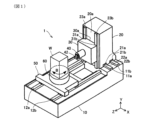
- FIG. 1 is a perspective view showing an overall configuration of a machine tool in the first embodiment.
- FIG. 2 is a diagram showing the thermal displacement correction device according to the first embodiment.
- FIG. 3 is a perspective view showing a tetrahedral primary element (thin lines) and a shape line of the column (thick lines) when a structural analysis is performed on the column in the first embodiment by the finite element method.
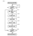
- FIG. 4 is a flowchart showing the optimization process of the coefficient matrix [W] and the temperature bias ⁇ b ⁇ in the first embodiment.
- FIG. 5 is a flowchart showing the thermal displacement correction process in the first embodiment.
- the machine tool has three mutually orthogonal linear axes (X-, Y-, and Z-axes) and a vertical rotation axis (B-axis) as drive axes.
- the machine tool 1 is composed of a bed 10, a column 20, a saddle 30, a rotating spindle 40, a table 50, a turntable 60, a temperature sensor 70, a control device 80, and a thermal displacement compensation device 90.
- the bed 10 is substantially rectangular and is placed on the floor.
- the shape of the bed 10 is not limited to a rectangular shape.
- a pair of X-axis guide rails 11a, 11b on which the column 20 can slide are formed on the upper surface of the bed 10 so as to extend in the X-axis direction (horizontal direction) and parallel to each other.
- an X-axis ball screw (not shown) for driving the column 20 in the X-axis direction is arranged between the pair of X-axis guide rails 11a, 11b on the bed 10, and an X-axis motor 11c is arranged to rotate and drive the X-axis ball screw.
- a pair of Z-axis guide rails 12a, 12b on which the table 50 can slide are formed on the upper surface of the bed 10 so as to extend in the Z-axis direction (horizontal direction) perpendicular to the X-axis direction and parallel to each other. Furthermore, a Z-axis ball screw (not shown) for driving the table 50 in the Z-axis direction is arranged between the pair of Z-axis guide rails 12a, 12b on the bed 10, and a Z-axis motor 12c for rotating and driving this Z-axis ball screw is arranged.
- a pair of X-axis guide grooves 21a, 21b are formed on the bottom surface (X-axis sliding surface) of the column 20 so as to extend in the X-axis direction and to be parallel to each other.
- the pair of X-axis guide grooves 21a, 21b are fitted onto a pair of X-axis guide rails 11a, 11b via ball guides 22a, 22b so that the column 20 can move in the X-axis direction relative to the bed 10.
- a pair of Y-axis guide rails 23a, 23b on which the saddle 30 can slide are formed so as to extend in the Y-axis direction (vertical direction) and parallel to each other. Furthermore, on the column 20, a Y-axis ball screw (not shown) for driving the saddle 30 in the Y-axis direction is arranged between the pair of Y-axis guide rails 23a, 23b, and a Y-axis motor 23c for rotating and driving this Y-axis ball screw is arranged.
- a pair of Y-axis guide grooves 31a, 31b are formed on the side surface 30a of the saddle 30 facing the Y-axis sliding surface 20a of the column 20 so as to extend in the Y-axis direction and to be parallel to each other.
- the pair of Y-axis guide grooves 31a, 31b are fitted into a pair of Y-axis guide rails 23a, 23b so that the saddle 30 can move in the Y-axis direction relative to the column 20.
- the rotating spindle 40 is rotatable by a spindle motor 41 housed in the saddle 30, and supports a tool 42.
- the tool 42 is fixed to the tip of the rotating spindle 40, and rotates with the rotation of the rotating spindle 40.
- the tool 42 also moves in the X-axis and Y-axis directions relative to the bed 10 with the movement of the column 20 and saddle 30. Examples of the tool 42 include a ball end mill, an end mill, a drill, and a tap.
- the table 50 is mounted on a pair of Z-axis guide rails 12a, 12b so that it can move in the Z-axis direction relative to the bed 10.
- a turntable 60 is supported on the top surface of the table 50 so that it can rotate around the vertical B-axis.
- the turntable 60 is rotatable by a B-axis motor 61 housed within the table 50, and the workpiece W is fixed by a jig, magnetic attraction, etc.
- the temperature sensor 70 shown in FIG. 2 is attached to any location of each structure of the machine tool 1, namely the bed 10, column 20, saddle 30, rotating spindle 40, table 50 and turntable 60.
- a thermocouple or a thermistor is used as this temperature sensor 70.
- the temperature information detected by the temperature sensor 70 is transmitted to a temperature acquisition unit 91, which will be described later, and is used for structural analysis of each structure of the machine tool 1.
- the control device 80 controls the spindle motor 41 to rotate the tool 42, and controls the X-axis motor 11c, the Z-axis motor 12c, the Y-axis motor 23c, and the B-axis motor 61 to move the workpiece W and the tool 42 relatively in the X-axis direction, the Z-axis direction, the Y-axis direction, and around the B-axis, thereby machining the workpiece W.
- the control device 80 also includes a thermal displacement correction device 90 that performs thermal displacement correction to eliminate deviations in the relative positions of the workpiece W and the tool 42 that occur due to thermal displacement of structures such as the bed 10 and the column 20.
- the thermal displacement correction device 90 is not limited to being provided inside the control device 80, and can also be applied as an external device.
- thin lines L1 and thick lines L2 are used.
- thick lines L2 are the shape lines of column 20.
- Thin lines L1 indicate boundary segments of elements in structural analysis using the finite element method, and the vertices of each thin line L1 are nodes. That is, in FIG. 3, the element is a primary tetrahedral element, and includes many nodes.
- one element is illustrated as a primary tetrahedral element, but this is not limited to this, and secondary tetrahedral elements, primary hexahedral elements, secondary hexahedral elements, etc. can also be applied.
- the machining command position is the position command value of the moving body of the machine tool 1 commanded by an NC program for machining, measurement, etc.
- the machining command position and the correction value are the command value of the tip position of the rotating spindle 40 relative to the workpiece W, that is, the command value of the tip position of the tool 42 relative to the workpiece W.
- the machining command position can also be regarded as a command position for each axis motor.
- this machining command position is expressed in X-axis, Y-axis, Z-axis, and B-axis coordinates.
- the correction value is expressed as X-axis, Y-axis, and Z-axis coordinates in order to perform correction for the X-axis, Y-axis, and Z-axis.
- the temperatures of all nodes are required as analysis conditions when structurally analyzing column 20 using the finite element method. Furthermore, instead of calculating the amount of thermal displacement for all nodes, only the amount of thermal displacement for a specified portion, for example, multiple nodes located near tool 42, is calculated. This makes it possible to significantly reduce the calculations required for structural analysis using the finite element method, and to speed up the calculations.
- the thermal displacement compensation device 90 includes a temperature acquisition unit 91, an FEM analysis unit 92, a coefficient matrix storage unit 93, a temperature bias acquisition unit 94, a compensation value calculation unit 95, a compensation unit 96, a comparison data acquisition unit 97, an error calculation unit 98, and an optimization processing unit 99. Each of these can be configured as separate hardware, or can be configured to be realized by software.
- the temperature acquisition unit 91 acquires the temperature detected by the temperature sensor 70 provided in the machine tool 1.
- the temperature acquisition unit 91 may acquire the temperature obtained by simulating the temperature of a specific part of the machine tool 1 using a calculation device (not shown).
- At least one, and more preferably multiple, temperature sensors 70 are arranged in the column 20.
- the FEM analysis unit 92 which serves as a finite element method analysis unit, performs structural analysis of the column 20 using the finite element method (FEM) and estimates the amount of thermal displacement at a specified portion of the column 20.
- FEM finite element method
- the conditions for this structural analysis require material constants, temperature information at all nodes, constraint conditions, and spring elements at the support portions. Of the conditions for the structural analysis, only the temperatures at all nodes change, and the other conditions are known. The temperatures at all nodes are calculated based on the temperatures acquired by the temperature acquisition unit 91 using the coefficient matrix [W] and temperature bias ⁇ b ⁇ described below.
- equation (1) structural analysis using the finite element method can be expressed by a matrix equation such as equation (1).
- equation (1) The method for deriving equation (1) for this structural analysis will be described later.
- the coefficient matrix storage unit 93 stores the coefficient matrix [W] used in structural analysis using the finite element method.
- the coefficient matrix [W] is optimized so that the difference between the amount of thermal displacement estimated by the FEM analysis unit 92 and the amount of thermal displacement obtained by actual measurement or simulation is minimized. This optimization is performed before the command position of the moving body of the machine tool is corrected by the thermal displacement correction device 90. In other words, with the optimized coefficient matrix [W] stored in the coefficient matrix storage unit 93, the command position of the moving body of the machine tool is corrected.
- the temperature bias acquisition unit 94 acquires the temperature bias ⁇ b ⁇ in the machine tool 1.
- the temperature bias ⁇ b ⁇ is acquired as a column vector.
- the temperature bias ⁇ b ⁇ can be various information in the machine tool 1, such as the initial temperature, temperature, machine coordinates, dimensional information, and linear expansion coefficient of each device provided in the machine tool 1.
- the temperature bias ⁇ b ⁇ is used in structural analysis using the finite element method.
- the temperature bias ⁇ b ⁇ , together with the coefficient matrix [W], is optimized by machine learning so that the difference between the thermal displacement amount estimated by the FEM analysis unit 92 and the thermal displacement amount acquired by actual measurement or simulation is minimized. This optimization is performed in advance, as in the case of the coefficient matrix [W].
- the initial value of the temperature bias ⁇ b ⁇ can be set appropriately by the user.
- the correction value calculation unit 95 calculates a correction value for the machining command position based on the amount of thermal displacement of a specific portion of the column 20 obtained by the FEM analysis unit 92.
- the correction unit 96 corrects the machining command position using the correction value obtained by the correction value calculation unit 95.
- the comparison data acquisition unit 97 acquires comparison data used for error calculation by the error calculation unit 98.
- the comparison data is a thermal displacement vector of a specific portion of the column 20 that is actually measured from the machine tool 1 or calculated by simulation.
- the error calculation unit 98 calculates the difference (error) between the comparison data acquired by the comparison data acquisition unit 97 and the thermal displacement vector of a specified portion of the structure (column 20) estimated by the FEM analysis unit 92.
- the difference can be calculated using a known loss function, such as the mean squared error (MSE), mean absolute error (MAE), root mean squared error (RMSE), mean squared logarithmic error (MSLE), Huber loss, Poisson loss, hinge loss, Kullback-Leibler divergence (KLD), etc.
- MSE mean squared error
- MAE mean absolute error
- RMSE root mean squared error
- MSLE mean squared logarithmic error
- Huber loss Poisson loss
- hinge loss hinge loss
- the optimization processing unit 99 adjusts the coefficient matrix [W] and temperature bias ⁇ b ⁇ used in the structural analysis by the finite element method so that the difference (error) calculated by the error calculation unit 98 is minimized.
- the adjusted coefficient matrix [W] is stored in the coefficient matrix storage unit 93 described above, and the adjusted temperature bias ⁇ b ⁇ is fed back to the temperature bias acquisition unit 94.
- the coefficient matrix [W] and temperature bias ⁇ b ⁇ are optimized by repeatedly performing adjustments by the optimization processing unit 99 as described below.
- the method of optimizing the coefficient matrix [W] and temperature bias ⁇ b ⁇ in the optimization processing unit 99 is not limited, and any known method can be adopted. For example, it can be performed by machine learning. Optimization based on artificial intelligence other than machine learning may also be performed. When performing it by machine learning, a known optimization algorithm can be used, and for example, the steepest descent method, SGD (Stochastic Gradient Descent), mini-batch SGD, momentum, RMSProp, Adam, etc. can be adopted as the optimization algorithm.
- SGD Spochastic Gradient Descent
- mini-batch SGD momentum
- RMSProp RMSProp
- Adam Adam
- step S1 temperature acquisition unit 91 acquires temperatures detected by each temperature sensor 70 provided in machine tool 1. At the same time, temperature bias ⁇ b ⁇ in machine tool 1 is also acquired.
- step S2 the FEM analysis unit 92 performs FEM analysis on the column 20 using the temperature and temperature bias ⁇ b ⁇ acquired in step S1 and the coefficient matrix [W] stored in the coefficient matrix storage unit 93, according to formula (1), to calculate the thermal displacement vector.
- a predetermined coefficient matrix [W] is stored in the coefficient matrix storage unit 93 as an initial value.
- step S3 the comparison data acquisition unit 97 acquires, as comparison data, a thermal displacement vector of a predetermined portion of the column 20 that is actually measured from the machine tool 1 or calculated by simulation. Then, in step S4, the error calculation unit 98 calculates the difference (error) between the comparison data acquired by the comparison data acquisition unit 97 and the thermal displacement vector of the column 20 estimated by the FEM analysis unit 92.
- step S5 the optimization processing unit 99 determines whether the error calculated by the error calculation unit 98 is equal to or less than a preset tolerance. If it is determined in step S5 that the error is not equal to or less than the preset tolerance, the process proceeds to No in step S5. Then, in step S6, the optimization processing unit 99 adjusts the coefficient matrix [W] and the temperature bias ⁇ b ⁇ , stores the adjusted coefficient matrix [W] in the coefficient matrix storage unit 93, and inputs the adjusted temperature bias ⁇ b ⁇ to the temperature bias acquisition unit 94. Then, the process returns to step S1, and the subsequent steps are performed again using the latest coefficient matrix [W] and temperature bias ⁇ b ⁇ . The adjustment of the coefficient matrix [W] and the temperature bias ⁇ b ⁇ by the optimization processing unit 99 is performed by optimization processing using machine learning based on a predetermined optimization algorithm.
- step S5 determines whether the error is equal to or less than the preset tolerance. If it is determined in step S5 that the error is equal to or less than the preset tolerance, the process proceeds to Yes in step S5 and ends the optimization process.
- the optimized coefficient matrix [W] is stored in the coefficient matrix storage unit 93, and the optimized temperature bias ⁇ b ⁇ is input to the temperature bias acquisition unit 94.
- thermal displacement compensation process by thermal displacement compensation device (thermal displacement compensation method)
- thermal displacement compensation process by the thermal displacement compensation device 90 will be described with reference to Fig. 5.
- the process by the thermal displacement compensation device 90 is performed after the power is turned on to the machine tool 1.
- the thermal displacement compensation process is performed when the workpiece W is measured by a touch probe (not shown) or the like.
- step S11 (corresponding to a temperature acquisition step)
- the temperature acquisition unit 91 continuously acquires the temperature of the column 20 from the temperature sensor 70.
- the temperature bias ⁇ b ⁇ in the optimized machine tool 1 is acquired by the temperature bias acquisition unit 94.
- step S12 corresponding to a finite element method analysis step
- the FEM analysis unit 92 executes FEM analysis for column 20 using the temperature and optimized temperature bias ⁇ b ⁇ acquired in step S1 and the optimized coefficient matrix [W] stored in the coefficient matrix storage unit 93 according to formula (1), and calculates the thermal displacement vector as an estimated value.
- the calculated thermal displacement vector is stored in a storage unit (not shown).
- the correction value calculation unit 95 calculates a correction value for the command position of the tip of the rotating spindle 40 based on an estimated value of the thermal displacement of a specified portion of the column 20 (a portion near the tool). For example, the thermal displacement of the tip position of the rotating spindle 40 is calculated based on the current Y-axis position of the saddle 30 and an estimated value of the thermal displacement of the sliding surface 20a corresponding to that Y-axis position. The thermal displacement of the tip position of the rotating spindle 40 calculated in this way becomes the correction value for the command position of the tip of the rotating spindle 40.
- step S14 the correction unit 96 corrects the command position of the tip of the rotating spindle 40 using the calculated correction value. That is, the command position output by the control device 80 is corrected to the corrected command position using the correction value.
- step S15 the control device 80 executes thermal displacement correction, and if the power supply to the machine tool 1 is not cut off in step S16, the process returns to step S11 and executes each step. That is, if the power supply to the machine tool 1 is not cut off, the process repeats the processing of steps S2 to S16, and if the power supply to the machine tool 1 is cut off, the thermal displacement correction processing ends.
- formula (2) is a stiffness equation for a structure.
- the stiffness matrix [K] is a known value obtained from the material constants of the column 20 and the shape of the column 20. Note that in formula (2), notation indicates the number of rows and columns, or the number of elements. Also, all vectors used in this specification refer to column vectors.
- the nodal force relational expression according to the nodal temperature is expressed by equation (3).
- the nodal force matrix [F] is a known value obtained from the material constants of column 20 and the shape of column 20. Note that in equation (2), notation is used to indicate the number of rows and columns, or the number of elements.
- the thermal displacement vector ⁇ all ⁇ of all nodes is expressed as in equation (4).
- the thermal displacement vector ⁇ all ⁇ of all nodes in equation (4) corresponds to the thermal displacement of all nodes.
- the multiplication matrix of the inverse matrix of the stiffness matrix [K] and the nodal force coefficient matrix [F] is expressed as [P], as in equation (5).
- the portion required for thermal displacement correction is not the entire column 20, but only the thermal displacement of the portion of the column 20 near the tool 42. Therefore, when the thermal displacement vector ⁇ all ⁇ of the formula (6) is divided into the thermal displacement vector ⁇ part1 ⁇ of the node of the portion of the column 20 near the tool 42 and the thermal displacement vector ⁇ part2 ⁇ of the node of the other portion, it is expressed as shown in the formula (6).
- the temperature vector ⁇ T all ⁇ of all the nodes of the structure can be expressed as ⁇ [W] ⁇ T sensor ⁇ + ⁇ b ⁇ . Therefore, the formula (7) can be expressed as the formula (8).
- formula (8) is synonymous with the above-mentioned formula (1). That is, formula (1) is derived in this manner.
- the first coefficient matrix [P part ] is a multiplication matrix of the inverse matrix of the stiffness matrix [K] and the nodal force coefficient matrix [F].
- the second coefficient matrix [W] is a coefficient matrix for calculating temperatures at all nodes of the column 20 from the temperatures of predetermined portions of the column 20 where the temperature sensor 70 is provided, which are acquired by the temperature acquisition unit 91.
- thermo displacement correction device 90 of the first embodiment a structural analysis is performed by the finite element method using a coefficient matrix [W] for calculating the temperatures at all nodes of the column 20 from the temperatures at the respective predetermined portions of the column 20 of the machine tool 1, and the thermal displacement amount at the predetermined nodes of the column 20 of the machine tool 1 is estimated, and the coefficient matrix [W] is optimized in advance so that the difference between the thermal displacement amount estimated by the finite element method analysis unit and the thermal displacement amount obtained by actual measurement or simulation is minimized.
- the thermal displacement amount at the actual nodes of the column 20 can be estimated with higher accuracy than when the thermal displacement amount is defined as constant for each block obtained by dividing the column 20, and therefore highly accurate thermal displacement correction can be performed.
- the coefficient matrix for calculating the temperatures at all nodes of the column 20 of the machine tool 1 from the temperatures of each specified part of the column 20 is optimized in advance. Therefore, compared to the case where an analysis for calculating the temperatures of all nodes, for example a temperature distribution analysis, is applied, the time required for calculation can be significantly shortened and the calculation speed of the thermal displacement vector ⁇ of all nodes can be increased. This calculation is performed in real time during machining, and thermal displacement correction is performed. In this way, structural analysis using the finite element method can be performed quickly, allowing thermal displacement correction to be performed in real time with high precision.
- the actual thermal displacement amount of the column 20 can be estimated with higher accuracy than when the thermal displacement amount is defined as constant for each block into which the column 20 is divided, making it possible to perform highly accurate thermal displacement correction.
- structural analysis by the finite element method can be performed at high speed, making it possible to perform highly accurate thermal displacement correction in real time.
- the temperature acquisition unit 91 acquires the temperature detected by the temperature sensor 70 provided at a predetermined location on the column 20 of the machine tool 1. This makes it possible to accurately acquire the temperature of the predetermined location on the column 20 as an actual measurement value.
- the temperature acquisition unit 91 may also acquire the temperature obtained by simulating the temperature of a specific portion of the column 20 of the machine tool 1. In this case, by providing the thermal displacement correction device 90 with a computing device that performs the simulation, it becomes unnecessary to use the temperature sensor 70, and it is possible to reduce the number of parts provided in the machine tool 1.
- the coefficient matrix [W] is optimized by machine learning. This allows the optimization process of the coefficient matrix [W] to be performed efficiently.
- the finite element method analysis unit 92 estimates the amount of thermal displacement at multiple nodes located near the tool 42 provided on the machine tool 1. This makes it possible to improve the machining accuracy of the workpiece by the tool 42.
- the coefficient matrix [W] is optimized so that the difference between the thermal displacement amount estimated by the finite element method analysis unit 92 and the thermal displacement amount obtained by actual measurement or simulation is minimized at all nodes of the structure 20. This improves the estimation accuracy of the thermal displacement amount vector estimated by the finite element method analysis unit 92, and allows for even more accurate thermal displacement correction.
- the finite element method analysis unit 92 is configured to perform structural analysis using the finite element method, using the temperature bias ⁇ b ⁇ related to the machine tool 1 together with the coefficient matrix [W].
- the temperature bias ⁇ b ⁇ , together with the coefficient matrix [W] is optimized by machine learning so that the difference between the thermal displacement amount estimated by the finite element method analysis unit 92 and the thermal displacement amount obtained by actual measurement or simulation is minimized.
- the estimation accuracy of the thermal displacement amount vector can be further improved, and thermal displacement correction can be performed with even higher accuracy.
- the machine tool 1 in this embodiment 1 also includes a thermal displacement compensation device 90 and a column 20, which is a moving body configured to move according to a command position corrected by the thermal displacement compensation device.
- the command position of the column 20 is set taking into account thermal displacement, so machining accuracy can be improved.
- thermo displacement correction device 90 for a machine tool 1, a thermal displacement correction method, and a machine tool that can perform structural analysis using the finite element method at high speed and perform thermal displacement correction in real time with high accuracy.
Landscapes
- Engineering & Computer Science (AREA)
- Mechanical Engineering (AREA)
- Human Computer Interaction (AREA)
- Manufacturing & Machinery (AREA)
- Physics & Mathematics (AREA)
- General Physics & Mathematics (AREA)
- Automation & Control Theory (AREA)
- Automatic Control Of Machine Tools (AREA)
- Numerical Control (AREA)
Priority Applications (4)
| Application Number | Priority Date | Filing Date | Title |
|---|---|---|---|
| CN202380094613.3A CN120770009A (zh) | 2023-03-30 | 2023-03-30 | 机床中的热位移修正装置和热位移修正方法以及机床 |
| JP2025509488A JPWO2024201885A1 (https=) | 2023-03-30 | 2023-03-30 | |
| PCT/JP2023/013142 WO2024201885A1 (ja) | 2023-03-30 | 2023-03-30 | 工作機械における熱変位補正装置及び熱変位補正方法並びに工作機械 |
| DE112023006098.3T DE112023006098T5 (de) | 2023-03-30 | 2023-03-30 | Thermischer-Versatz-Korrekturvorrichtung und Thermischer-Versatz-Korrekturverfahren für eine Werkzeugmaschine und Werkzeugmaschine |
Applications Claiming Priority (1)
| Application Number | Priority Date | Filing Date | Title |
|---|---|---|---|
| PCT/JP2023/013142 WO2024201885A1 (ja) | 2023-03-30 | 2023-03-30 | 工作機械における熱変位補正装置及び熱変位補正方法並びに工作機械 |
Publications (1)
| Publication Number | Publication Date |
|---|---|
| WO2024201885A1 true WO2024201885A1 (ja) | 2024-10-03 |
Family
ID=92904365
Family Applications (1)
| Application Number | Title | Priority Date | Filing Date |
|---|---|---|---|
| PCT/JP2023/013142 Ceased WO2024201885A1 (ja) | 2023-03-30 | 2023-03-30 | 工作機械における熱変位補正装置及び熱変位補正方法並びに工作機械 |
Country Status (4)
| Country | Link |
|---|---|
| JP (1) | JPWO2024201885A1 (https=) |
| CN (1) | CN120770009A (https=) |
| DE (1) | DE112023006098T5 (https=) |
| WO (1) | WO2024201885A1 (https=) |
Citations (4)
| Publication number | Priority date | Publication date | Assignee | Title |
|---|---|---|---|---|
| JP2016002637A (ja) * | 2014-06-18 | 2016-01-12 | 株式会社ジェイテクト | 工作機械の熱変位量推定装置に用いる条件決定方法 |
| JP2019111648A (ja) * | 2019-04-23 | 2019-07-11 | ファナック株式会社 | 機械学習装置及び熱変位補正装置 |
| CN112364444A (zh) * | 2020-09-23 | 2021-02-12 | 江苏赛洋机电科技有限公司 | 一种基于有限元模型数值仿真的数控机床温度测点优化方法 |
| JP2022532018A (ja) * | 2019-04-05 | 2022-07-13 | ディッケル マホ ゼーバッハ ゲーエムベーハー | 数値制御された工作機械の熱的に誘発された位置変化を補償するための方法および装置 |
Family Cites Families (1)
| Publication number | Priority date | Publication date | Assignee | Title |
|---|---|---|---|---|
| US9317084B2 (en) | 2011-05-17 | 2016-04-19 | Jtekt Corporation | Thermal displacement compensating device and method for a machine tool |
-
2023
- 2023-03-30 JP JP2025509488A patent/JPWO2024201885A1/ja active Pending
- 2023-03-30 CN CN202380094613.3A patent/CN120770009A/zh active Pending
- 2023-03-30 WO PCT/JP2023/013142 patent/WO2024201885A1/ja not_active Ceased
- 2023-03-30 DE DE112023006098.3T patent/DE112023006098T5/de active Pending
Patent Citations (4)
| Publication number | Priority date | Publication date | Assignee | Title |
|---|---|---|---|---|
| JP2016002637A (ja) * | 2014-06-18 | 2016-01-12 | 株式会社ジェイテクト | 工作機械の熱変位量推定装置に用いる条件決定方法 |
| JP2022532018A (ja) * | 2019-04-05 | 2022-07-13 | ディッケル マホ ゼーバッハ ゲーエムベーハー | 数値制御された工作機械の熱的に誘発された位置変化を補償するための方法および装置 |
| JP2019111648A (ja) * | 2019-04-23 | 2019-07-11 | ファナック株式会社 | 機械学習装置及び熱変位補正装置 |
| CN112364444A (zh) * | 2020-09-23 | 2021-02-12 | 江苏赛洋机电科技有限公司 | 一种基于有限元模型数值仿真的数控机床温度测点优化方法 |
Also Published As
| Publication number | Publication date |
|---|---|
| JPWO2024201885A1 (https=) | 2024-10-03 |
| CN120770009A (zh) | 2025-10-10 |
| DE112023006098T5 (de) | 2026-02-26 |
Similar Documents
| Publication | Publication Date | Title |
|---|---|---|
| US9317084B2 (en) | Thermal displacement compensating device and method for a machine tool | |
| JP7514322B2 (ja) | 工作機械制御及び工作機械に対する特性図に基づく誤差補償のための方法 | |
| Shen et al. | On-line asynchronous compensation methods for static/quasi-static error implemented on CNC machine tools | |
| JP4735795B2 (ja) | 冗長マニピュレータの制御方法 | |
| JP5399624B2 (ja) | 数値制御方法及び数値制御装置 | |
| CN102649246B (zh) | 补偿计算机数字控制机加工系统的尺寸精度的系统和方法 | |
| JP2012240137A (ja) | 工作機械の熱変位補正方法および熱変位補正装置 | |
| KR20210083176A (ko) | 열 변위 보정 장치 | |
| CN116339233B (zh) | 基于激光干涉跟踪仪测量场的机床误差控制方法及系统 | |
| JP2003094291A (ja) | 工作機械の熱変形補正方法および装置 | |
| JP7158582B2 (ja) | 調整量推定装置、調整量推定方法、調整量推定プログラム及び工作機械組立方法 | |
| JP6221419B2 (ja) | 工作機械の温度測定位置決定方法およびそのための装置 | |
| JP6648500B2 (ja) | 工作機械の熱変位補正装置 | |
| JP2015030083A (ja) | 工作機械の各部材の線膨張係数の決定方法および工作機械の熱変位補正装置 | |
| WO2024201885A1 (ja) | 工作機械における熱変位補正装置及び熱変位補正方法並びに工作機械 | |
| Fu et al. | Review on structure-based errors of parallel kinematic machines in comparison with traditional NC machines | |
| JP6435655B2 (ja) | 工作機械の熱変位量推定装置に用いる条件決定方法 | |
| Jeon et al. | A calibration method of redundantly actuated parallel mechanism machines based on projection technique | |
| WO2025164409A1 (ja) | 産業機械の熱変位補正装置及び熱変位補正方法 | |
| RU2573854C1 (ru) | Способ компенсации тепловых деформаций металлорежущих станков с чпу | |
| Ko et al. | Quasistatic Error Modeling and Model Testing for a 5-Axis Machine | |
| Tan et al. | RBF-based compensation method on displacement and thermal error | |
| WO2023223571A1 (ja) | 工具経路補正装置、工作機械システム、工具経路の補正方法およびプログラム | |
| Laspas | Modeling and measurement of geometric error of machine tools: Methodology and implementation | |
| JP2016112660A (ja) | 工作機械の熱変位量推定装置に用いる温度検出位置の条件決定方法 |
Legal Events
| Date | Code | Title | Description |
|---|---|---|---|
| 121 | Ep: the epo has been informed by wipo that ep was designated in this application |
Ref document number: 23930523 Country of ref document: EP Kind code of ref document: A1 |
|
| WWE | Wipo information: entry into national phase |
Ref document number: 2025509488 Country of ref document: JP |
|
| WWE | Wipo information: entry into national phase |
Ref document number: 202380094613.3 Country of ref document: CN |
|
| WWP | Wipo information: published in national office |
Ref document number: 202380094613.3 Country of ref document: CN |
|
| WWE | Wipo information: entry into national phase |
Ref document number: 112023006098 Country of ref document: DE |
|
| WWP | Wipo information: published in national office |
Ref document number: 112023006098 Country of ref document: DE |
|
| 122 | Ep: pct application non-entry in european phase |
Ref document number: 23930523 Country of ref document: EP Kind code of ref document: A1 |