WO2024201875A1 - 電動コンプレッサ装置 - Google Patents
電動コンプレッサ装置 Download PDFInfo
- Publication number
- WO2024201875A1 WO2024201875A1 PCT/JP2023/013105 JP2023013105W WO2024201875A1 WO 2024201875 A1 WO2024201875 A1 WO 2024201875A1 JP 2023013105 W JP2023013105 W JP 2023013105W WO 2024201875 A1 WO2024201875 A1 WO 2024201875A1
- Authority
- WO
- WIPO (PCT)
- Prior art keywords
- cooling
- rib
- passage
- circumferential direction
- electric compressor
- Prior art date
- Legal status (The legal status is an assumption and is not a legal conclusion. Google has not performed a legal analysis and makes no representation as to the accuracy of the status listed.)
- Ceased
Links
Images




Classifications
-
- F—MECHANICAL ENGINEERING; LIGHTING; HEATING; WEAPONS; BLASTING
- F04—POSITIVE - DISPLACEMENT MACHINES FOR LIQUIDS; PUMPS FOR LIQUIDS OR ELASTIC FLUIDS
- F04D—NON-POSITIVE-DISPLACEMENT PUMPS
- F04D29/00—Details, component parts, or accessories
- F04D29/58—Cooling; Heating; Diminishing heat transfer
- F04D29/5806—Cooling the drive system
-
- F—MECHANICAL ENGINEERING; LIGHTING; HEATING; WEAPONS; BLASTING
- F04—POSITIVE - DISPLACEMENT MACHINES FOR LIQUIDS; PUMPS FOR LIQUIDS OR ELASTIC FLUIDS
- F04D—NON-POSITIVE-DISPLACEMENT PUMPS
- F04D25/00—Pumping installations or systems
- F04D25/02—Units comprising pumps and their driving means
- F04D25/06—Units comprising pumps and their driving means the pump being electrically driven
-
- F—MECHANICAL ENGINEERING; LIGHTING; HEATING; WEAPONS; BLASTING
- F05—INDEXING SCHEMES RELATING TO ENGINES OR PUMPS IN VARIOUS SUBCLASSES OF CLASSES F01-F04
- F05D—INDEXING SCHEME FOR ASPECTS RELATING TO NON-POSITIVE-DISPLACEMENT MACHINES OR ENGINES, GAS-TURBINES OR JET-PROPULSION PLANTS
- F05D2260/00—Function
- F05D2260/20—Heat transfer, e.g. cooling
- F05D2260/221—Improvement of heat transfer
- F05D2260/2214—Improvement of heat transfer by increasing the heat transfer surface
- F05D2260/22141—Improvement of heat transfer by increasing the heat transfer surface using fins or ribs
Definitions
- This disclosure relates to an electric compressor device.
- electric compressor devices that include a motor housing in which a coolant flow path is formed.
- the coolant flowing through the flow path cools the stator of the motor that constitutes the electric compressor device.
- the motor housing disclosed in Patent Document 1 has a coolant passageway that extends in the circumferential direction.
- an electric compressor device A rotation axis; A compressor wheel provided on the rotating shaft; A motor for driving the rotating shaft; a motor housing that houses the motor; Equipped with The motor is A rotor fixed to the rotating shaft; a stator disposed around the rotor and supported by the motor housing; Including, A cooling flow passage is formed inside the motor housing at a position radially outside the stator through which a cooling liquid flows in a circumferential direction, When viewed along the circumferential direction, an axial length of the cooling passage is at least twice as long as a radial length of the cooling passage, At least one rib is provided which protrudes radially outward from an inner peripheral wall surface of the motor housing that defines the cooling flow passage and extends in the circumferential direction.
- expressions indicating that things are in an equal state such as “identical,””equal,” and “homogeneous,” not only indicate a state of strict equality, but also indicate a state in which there is a tolerance or a difference to the extent that the same function is obtained.
- expressions describing shapes such as a rectangular shape or a cylindrical shape do not only refer to rectangular shapes, cylindrical shapes, etc. in the strict geometric sense, but also refer to shapes that include uneven portions, chamfered portions, etc., to the extent that the same effect is obtained.
- the expressions “comprise”, “include”, or “have” a certain element are not exclusive expressions excluding the presence of other elements.
- the same components are denoted by the same reference numerals and the description thereof may be omitted.
- the direction in which the axis of the rotating shaft 2 extends is referred to as the "axial direction”, and the circumferential and radial directions based on the axis are sometimes simply referred to as the “circumferential direction” and "radial direction”.
- the outer radial direction is the side that moves away from the axis of the rotating shaft 2, and the inner radial direction is the side that moves closer to the axis.
- the electric compressor device 1 includes a housing 20 that houses the rotating shaft 2.
- the housing 20 includes a low-pressure side housing 23 that houses the low-pressure wheel 13 provided at one end of the rotating shaft 2, a high-pressure side housing 24 that houses the high-pressure wheel 14 provided at the other end of the rotating shaft 2, and a motor housing 25 that houses the motor 5 for driving the rotating shaft 2.
- the low-pressure side housing 23 and the high-pressure side housing 24 are arranged to sandwich the motor housing 25 in the axial direction.
- the motor 5 includes a rotor 51 fixed to the rotating shaft 2 between the high-pressure wheel 14 and the low-pressure wheel 13, and a stator 52 arranged around the rotor 51.
- the rotor 51 has a rotor core supported by the rotating shaft 2 and a plurality of permanent magnets supported by the rotor core.
- the stator 52 also has a stator core 53 extending in the circumferential direction and a stator coil 54 provided on the stator core 53.
- the stator core 53 is supported by the motor housing 25.
- the operation of the electric compressor device 1 is as follows. A rotating magnetic field is formed by the current flowing through the stator coil 54, and the rotor 51 starts to rotate together with the rotating shaft 2. As a result, the low-pressure wheel 13 and the high-pressure wheel 14 also start to rotate.
- air is drawn in from the suction port 236 (arrow A1). The drawn in air is accelerated by the centrifugal force of the low-pressure wheel 13, and the accelerated air is decelerated and pressurized by the diffuser 237, then flows through the scroll section 238 and is discharged from the discharge port (arrow A2). The low-pressure air compressed by the low-pressure compressor 3 is sent to the suction port 246 via the connecting pipe (arrow A3).
- the low-pressure air that passes through the suction port 246 is accelerated by the centrifugal force of the high-pressure wheel 14.
- the accelerated air is decelerated and pressurized by the diffuser 247, then flows through the scroll section 248 and is discharged from the discharge port (arrow A4).
- the motor housing 25 is formed with a cooling flow passage 40 radially outside the stator 52, through which a cooling liquid (not shown) can flow circumferentially.
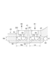
- FIG. 2 is a partially enlarged view of FIG. 1.
- the cooling flow passage 40 of this example has a first cooling flow passage 41, a second cooling flow passage 42, and a first turned-back cooling flow passage 46.
- the first cooling flow passage 41 and the second cooling flow passage 42 extend in the circumferential direction and are arranged to be aligned in the axial direction.
- the first turned-back cooling flow passage 46 is connected to the first cooling flow passage 41 and the second cooling flow passage 42.
- the cooling liquid that has passed through the inlet 251 formed in the motor housing 25 flows into the first cooling flow passage 41 (arrow B1).
- the cooling liquid also flows through the first cooling flow passage 41, the first turned-back cooling flow passage 46, and the second cooling flow passage 42 in order, and is discharged from an outlet 252 formed in the motor housing 25 (arrow B2).
- the axial length of the cooling flow passage 40 is at least twice its radial length, more specifically at least four times.
- the ratio of the axial length to the radial length is defined as the aspect ratio
- an axial length that is N times or more larger than the radial length is synonymous with an aspect ratio of 1/N or less.
- the aspect ratio of the cooling flow passage 40 in this example is 0.5 or less, more specifically 0.25 or less.
- the aspect ratio of 0.25 or less only needs to be established for at least the circumferentially extending cooling passages 40. That is, in the example of Figs. 1 and 2, the aspect ratio of the first cooling passage 41 and the second cooling passage 42 needs to be 0.25 or less.
- the axial length and radial length of the first cooling passage 41 correspond to dimensions La and Ld, respectively, in Fig. 2.
- the axial length and radial length of the second cooling passage 42 correspond to dimensions Ma and Md, respectively.
- dimension La is at least four times dimension Ld
- dimension Ma is at least four times dimension Md.
- the cross section of the first turned cooling passage 46 also has a similar shape. More specifically, when viewed along the axial direction, the circumferential length of the first turned cooling passage 46 is at least twice, and more specifically at least four times, the radial length of the first turned cooling passage 46 (not shown).
- the motor housing 25 includes at least one rib 70 extending circumferentially in the cooling passage 40. More specifically, the motor housing 25 includes a wall surface 60 that defines the cooling passage 40, and the wall surface 60 has an inner circumferential wall surface 62 and an outer circumferential wall surface 64.
- the rib 70 protrudes radially outward from the inner circumferential wall surface 62.
- the rib 70 is a convex surface that is integrally formed with the inner circumferential wall surface 62.
- the ribs 70 are arranged at intervals in the axial direction.
- the ribs 70 include a plurality of first ribs 71 arranged at intervals in the axial direction in the first cooling flow passage 41, and a plurality of second ribs 72 arranged at intervals in the axial direction in the second cooling flow passage 42.
- Each of the first ribs 71 and each of the second ribs 72 extend in the circumferential direction.
- the aspect ratio of the cooling flow passage 40 is smaller than 1, so the flow rate of the cooling liquid in the cooling flow passage 40 increases, and the provision of at least one rib 70 appropriately narrows the flow passage cross-sectional area, further increasing the flow rate of the cooling liquid.
- This increases the heat transfer coefficient between the cooling flow passage 40 and the cooling liquid.
- the provision of the rib 70 also increases the heat transfer area.
- an electric compressor device 1 with improved cooling performance is realized.
- the heat transfer area is further increased, further improving the cooling performance of the electric compressor device 1.
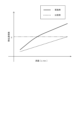
- FIG. 3 is a schematic graph showing the relationship between the flow rate of the coolant and the heat transfer coefficient determined by analysis.
- the solid line indicates the cooling flow path 40 of the embodiment having an aspect ratio of 0.25
- the dashed line indicates the cooling flow path of the comparative example (not shown) having an aspect ratio of 1.
- the heat transfer coefficient of the cooling flow path 40 is greater than that of the cooling flow path of the comparative example.
- the flow rate of the coolant required to achieve the required heat transfer coefficient (E shown in the graph) in the electric compressor device 1 is less for the cooling flow path 40 of the embodiment than for the cooling flow path of the comparative example. Therefore, it is also possible in the electric compressor device 1 to reduce the flow rate of the coolant flowing through the cooling flow path 40.
- cooling passage 40 in other examples may not have the second cooling passage 42 and the first return cooling passage 46, and may be configured only with the first cooling passage 41.
- first cooling passage 41 may have only one first rib 71.
- ⁇ Rib 70 according to some embodiments> 4A and 4B show a first rib 71 constituting the rib 70.
- Fig. 4A is a schematic cross-sectional view of the first rib 71A (71)
- Fig. 4B is a schematic cross-sectional view of the first rib 71B (71).
- At least one of the configurations relating to the first ribs 71A and 71B described below may be applied to the second rib 72 (see Fig. 2).
- the above configuration makes it possible to avoid an excessive increase in the flow rate of the cooling liquid and the associated increase in pressure loss caused by the shortest distance between the first rib 71 and the side surface 65 being too short.
- the above-mentioned relationship between the dimensions Wf and Wt may also be established for the second rib 72. That is, the shortest distance between a side surface (not shown) of the wall surface 60 that defines the second cooling flow passage 42 and the second rib 72 closest to that side surface may be longer than the axial length of the top of the second rib 72.
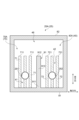
- the first extension portion 913 extends parallel to the first rib 71 and the second rib 72. 6A and 6B, the circumferential range in which the first cooling flow passage 41 is disposed and the circumferential range in which the second cooling flow passage 42 is disposed are both the same as the circumferential range in which the first partition wall 91 is disposed.
- the first turned cooling flow passage 46 is disposed at a position offset in the circumferential direction from the first partition wall 91.
- the inlet 251 is formed in the first cooling passage 41, and the outlet 252 is formed in the second cooling passage 42.
- the cooling liquid that passes through the inlet 251 flows through the first cooling passage 41, then flows through the first return cooling passage 46 and the second cooling passage 42 in that order, and is discharged from the outlet 252.
- the arrangement of the first turning cooling passage 46 makes it possible to lengthen the axial length of the cooling passage 40 (in other words, the axial length of the motor housing 25), further improving the cooling performance of the electric compressor device 1.
- the arrangement of the first turning cooling passage 46 allows the coolant to move back and forth in the circumferential direction, increasing the passage length of the cooling passage 40 and improving the cooling performance of the electric compressor device 1.
- all of the ribs 70A (70) according to the first embodiment are positioned so as to be offset from the first turned cooling flow passage 46 in the circumferential direction. More specifically, the first rib 71 and the second rib 72 are positioned in a circumferential range offset from the first turned cooling flow passage 46. In the illustrated example, one end 711 of the first rib 71 and one end 721 of the second rib 72 may be positioned at the same circumferential position as the first flow passage forming end 912. With the above configuration, the shape of the motor housing 25A can be simplified, making it easier to manufacture the motor housing 25A.
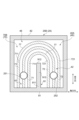
- the rib 70B (70) further includes a first curved rib 77 arranged in the first return cooling flow passage 46.
- the first curved rib 77 connects to one end 711 of the first rib 71 and one end 721 of the second rib 72, and curves in an arc shape so as to be convex toward the second body end 82.
- a plurality of first curved ribs 77 are arranged, and each first curved rib 77 connects to one end 711 of each first rib 71 and one end 721 of each second rib 72.
- the above configuration increases the heat transfer area in the first turning cooling passage 46, further improving the cooling performance of the electric compressor device 1.
- the coolant in the first turning cooling passage 46 can flow along the first curved rib 77, reducing the pressure loss of the coolant in the first turning cooling passage 46.
- ⁇ Details of the motor housing 25 and the cooling passage 40 according to another embodiment> 6C and 6D respectively show a motor housing 25C (25) according to the third embodiment and a motor housing 25D (25) according to the fourth embodiment.
- the cooling passage 40B (40) of the motor housing 25C, 25D (25) further includes a third cooling passage 43 and a second turned cooling passage 48 in addition to the first cooling passage 41, the second cooling passage 42, and the first turned cooling passage 46.
- the third cooling passage 43 is aligned with the first cooling passage 41 and the second cooling passage 42 in the axial direction and extends in the circumferential direction.
- the second turned cooling passage 48 communicates with the second cooling passage 42 and the third cooling passage 43.
- the illustrated ribs 70C, 70D (70) further include a third rib 73 extending in the circumferential direction in the third cooling passage 43 in addition to the first rib 71 and the second rib 72.
- three third ribs 73 are arranged axially spaced apart in the third cooling passage 43 .
- the motor housing 25C, 25D (25) shown in Figures 6C and 6D further includes a second partition wall 92.
- the second partition wall 92 extends in the circumferential direction so as to divide the cooling passages 40C, 40D (40) into the second cooling passage 42, the third cooling passage 43, and the third cooling passage 43. More specifically, the second partition wall 92 has a second connection end 921 connected to the second main body end 82, a second passage forming end 922 circumferentially facing the first main body end 81 with the second return cooling passage 48 in between, and a second extension portion 923 extending in the circumferential direction between the second connection end 921 and the second passage forming end 922. The second extension portion 923 extends parallel to the second rib 72 and the third rib 73.
- the second turned cooling channel 48 is disposed at a position offset in the circumferential direction with respect to the second rib 72 and the third rib 73.
- the first rib 71 and the third rib 73 have the same circumferential length, and the second rib 72 has a shorter circumferential length than the first rib 71 and the third rib 73.
- the first cooling channel 41 and the third cooling channel 43 have the same circumferential length, and the second cooling channel 42 has a shorter circumferential length than the first cooling channel 41 and the third cooling channel 43.
- the second turned cooling channel 48 has the same circumferential length and axial length as the first cooling channel 41, respectively.
- the inlet 251 is formed in the first cooling passage 41, and the outlet 252 is formed in the third cooling passage 43.
- the cooling liquid that passes through the inlet 251 flows in order through the first cooling passage 41, the first return cooling passage 46, the second cooling passage 42, the second return cooling passage 48, and the third cooling passage 43, and is discharged from the outlet 252.
- the second turning cooling passage 48 in addition to the first turning cooling passage 46, the axial length of the cooling passage 40 (in other words, the axial length of the motor housing 25) can be lengthened, and the cooling performance of the electric compressor device 1 is further improved.
- the second turning cooling passage 48 by further arranging the second turning cooling passage 48, the number of times the coolant travels back and forth in the circumferential direction increases, so the passage length of the cooling passage 40 increases, and the cooling performance of the electric compressor device 1 is improved.
- the second rib 72 and the third rib 73 are disposed in a circumferential range offset from the second return cooling flow passage 48.
- the other end 722 of the second rib 72 and one end 731 of the third rib 73 may be disposed in the same circumferential position as the second flow passage forming end 922.
- the rib 70D (70) illustrated in FIG. 6D further includes a second curved rib 78 that is also disposed in the second return cooling passage 48.
- the second curved rib 78 is connected to the other end 722 of the second rib 72 and one end 731 of the third rib 73, and is curved in an arc shape that is convex toward the first body end 81.
- multiple second curved ribs 78 are disposed, and each second curved rib 78 is connected to the other end 722 of each second rib 72 and one end 731 of each third rib 73.
- the above configuration increases the heat transfer area in the second cooling passage 42, further improving the cooling performance of the electric compressor device 1.
- the coolant in the second cooling passage 42 can flow along the second curved rib 78, reducing the pressure loss of the coolant in the second return cooling passage 48.
- the electric compressor device 1 is not limited to the two-stage compression type electric compressor shown in Fig. 1.
- the electric compressor device 1 may be a single-stage compression type electric compressor incorporated in a turbocharger device.
- the radial length of the first curved rib 77 may be shorter than at least one of the radial length of the first rib 71 and the radial length of the second rib 72. In this case, the cooling liquid flowing along the first curved rib 77 in the first turned cooling passage 46 can run up the first curved rib 77 and flow, thereby reducing pressure loss in the first turned cooling passage 46.
- the first curved rib 77 is not limited to extending continuously between one end 711 of the first rib 71 and one end 721 of the second rib 72.
- the first curved rib 77 may have a first through hole penetrating in the circumferential direction.
- the first curved rib 77 may include a first connecting curved rib extending in an arc shape from the one end 711 and a second connecting curved rib extending in an arc shape from the one end 721, and a gap may be formed as a first through hole between the first connecting curved rib and the second connecting curved rib.
- the first connecting curved rib and the second connecting curved rib have the same radius of curvature.
- the cooling liquid flowing through the first turned cooling flow passage 46 can also pass through the gap, and heat transfer in the first turned cooling flow passage 46 can be improved compared to the case where the flow of the cooling liquid along the circumferential direction is restricted by the first curved rib 77.
- the second curved rib 78 is not limited to extending continuously between the other end 722 of the second rib 72 and one end 731 of the third rib 73.
- the second curved rib 78 may have a second through hole formed therethrough in the circumferential direction.
- the second curved rib 78 may include a third connecting curved rib extending in an arc shape from the other end 722 and a fourth connecting curved rib extending in an arc shape from the one end 731, and a gap may be formed as a second through hole between the third connecting curved rib and the fourth connecting curved rib.
- the third connecting curved rib and the fourth connecting curved rib have the same radius of curvature.
- the cooling liquid flowing through the second turned cooling passage 48 can also pass through the gap, and heat transfer in the second turned cooling passage 48 can be improved compared to the case where the flow of the cooling liquid along the circumferential direction is restricted by the second curved rib 78.
- At least one embodiment of the electric compressor device (1) includes: A rotating shaft (2); A compressor wheel (at least one of a low pressure wheel 13 and a high pressure wheel 14) provided on the rotating shaft; A motor (5) for driving the rotating shaft; A motor housing (25) that houses the motor; Equipped with The motor is A rotor (51) fixed to the rotating shaft; a stator (52) disposed around the rotor and supported by the motor housing; Including, A cooling flow passage (40) is formed inside the motor housing, radially outside the stator, through which a cooling liquid flows in a circumferential direction, When viewed along the circumferential direction, an axial length of the cooling passage is at least twice as long as a radial length of the cooling passage, At least one rib (70) is provided which protrudes radially outward from an inner peripheral wall surface (62) of the wall surface (60) of the motor housing which defines the cooling flow passage and extends in the circumferential direction.
- the radial length of the rib is less than or equal to 4/5 of the maximum radial length of the cooling passage.
- the configuration described above in 3) further increases the heat transfer area, further improving the cooling performance of the electric compressor device.
- Each of the plurality of ribs has an apex (175) that is an outer end in the radial direction, The ribs are spaced apart in the axial direction at intervals greater than the axial length of the top portion.
- the configuration of 4) above makes it possible to avoid an excessive increase in the flow rate of the coolant and the associated increase in pressure loss caused by the distance between two adjacent ribs being too short.
- each of the plurality of ribs has a trapezoidal or rectangular shape.
- each of the plurality of ribs has an apex (175) that is an outer end in the radial direction
- the wall surface of the motor housing includes an axially facing side surface (65) that defines the cooling passage, The distance between the rib closest to the side surface and the side surface is greater than the axial length of the apex.
- the configuration of 6) above makes it possible to avoid an excessive increase in the flow rate of the coolant and the associated increase in pressure loss caused by the distance between the rib and the side being too short.
- the electric compressor device according to any one of 3) to 6) above,
- the number of the ribs arranged in the cooling passage extending in the circumferential direction is three or more.
- the configuration of 7) above further increases the heat transfer area, further improving the cooling performance of the electric compressor device.
- the motor housing includes: A first main body end portion (81) which is one end portion in the circumferential direction; A second body end portion (82) which is the other end portion in the circumferential direction and faces the first body end portion with a gap (M) therebetween; a first partition wall (91) extending in the circumferential direction so as to partition the cooling flow passage into a first cooling flow passage (41) and a second cooling flow passage (42) arranged in an axial direction, and a first turned-back cooling flow passage (46) communicating with the first cooling flow passage and the second cooling flow passage; Including, The first partition wall is a first connecting end (911) connected to the first body end; The second main body end portion and a first flow passage forming end portion (912) opposed to each other in the circumferential direction are disposed between the first turned cooling flow passage.
- the axial length of the cooling passage can be increased by providing a first return cooling passage in the cooling passage, thereby further improving the cooling performance of the electric compressor device.
- the electric compressor device according to 8) above,
- the at least one rib is positioned such that all of the ribs are offset from the first turning cooling passage in the circumferential direction.
- the at least one rib is a first rib (71) extending in the circumferential direction in the first cooling flow passage; a second rib (72) extending in the circumferential direction in the second cooling flow passage;
- the first curved rib (77) is a curved rib that is curved convexly toward the second main body end in the first return cooling flow passage, and connects one end (711) of the first rib and one end (721) of the second rib.
- the configuration of 10) above can increase the heat transfer area in the first turning cooling passage, further improving the cooling performance of the electric compressor device.
- the cooling liquid can flow along the curved ribs in the first turning cooling passage, reducing the pressure loss of the cooling liquid in the first turning cooling passage.
- the motor housing includes: a second partition wall (92) extending in the circumferential direction so as to partition the cooling flow passage into the second cooling flow passage and the third cooling flow passage (43) arranged in the axial direction, and a second turned-back cooling flow passage (48) communicating with the second cooling flow passage and the third cooling flow passage,
- the second partition wall is a second connecting end (921) connected to the second body end;
- the first main body end portion and a second flow passage forming end portion (922) opposed to each other in the circumferential direction are disposed between the first main body end portion and the second turned cooling flow passage.
- the axial length of the cooling passage can be further increased by further providing a second return cooling passage in the cooling passage, thereby further improving the cooling performance of the electric compressor device.
Landscapes
- Engineering & Computer Science (AREA)
- Mechanical Engineering (AREA)
- General Engineering & Computer Science (AREA)
- Physics & Mathematics (AREA)
- Thermal Sciences (AREA)
- Structures Of Non-Positive Displacement Pumps (AREA)
- Motor Or Generator Cooling System (AREA)
Abstract
Description
回転軸と、
前記回転軸に設けられたコンプレッサホイールと、
前記回転軸を駆動するためのモータと、
前記モータを収容するモータハウジングと、
を備え、
前記モータは、
前記回転軸に固定されたロータと、
前記ロータの周囲に配置され、前記モータハウジングによって支持されるステータと、
を含み、
前記モータハウジングの内部には、前記ステータよりも径方向の外側において冷却液が周方向に沿って流れるための冷却流路が形成され、
前記周方向に沿って視たとき、前記冷却流路の軸方向長さが前記冷却流路の径方向長さよりも2倍以上あり、
前記冷却流路を画定する前記モータハウジングの壁面のうち内周側壁面から前記径方向の外側に突出すると共に、前記周方向に延在する少なくとも1つのリブが設けられる。
例えば、「ある方向に」、「ある方向に沿って」、「平行」、「直交」、「中心」、「同心」或いは「同軸」等の相対的或いは絶対的な配置を表す表現は、厳密にそのような配置を表すのみならず、公差、若しくは、同じ機能が得られる程度の角度や距離をもって相対的に変位している状態も表すものとする。
例えば、「同一」、「等しい」及び「均質」等の物事が等しい状態であることを表す表現は、厳密に等しい状態を表すのみならず、公差、若しくは、同じ機能が得られる程度の差が存在している状態も表すものとする。
例えば、四角形状や円筒形状等の形状を表す表現は、幾何学的に厳密な意味での四角形状や円筒形状等の形状を表すのみならず、同じ効果が得られる範囲で、凹凸部や面取り部等を含む形状も表すものとする。
一方、一の構成要素を「備える」、「含む」、又は、「有する」という表現は、他の構成要素の存在を除外する排他的な表現ではない。
なお、同様の構成については同じ符号を付し説明を省略することがある。
図1は、本開示の一実施形態に係る電動コンプレッサ装置1の概略的な断面図である。本例の電動コンプレッサ装置1は回転軸2を備えた2段圧縮式電動コンプレッサである。2段圧縮式電動コンプレッサは例えば車両に搭載された燃料電池に圧縮空気を送るように構成される。
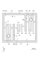
図1、図2を参照して本開示の一実施形態に係る冷却流路40を例示する。図2は、図1の部分拡大図である。本例の冷却流路40は、第1冷却流路41、第2冷却流路42、および、第1折返冷却流路46を有する。第1冷却流路41と第2冷却流路42は周方向に延在すると共に、軸方向において並ぶように配置されている。第1折返冷却流路46は、第1冷却流路41および第2冷却流路42に連通している。モータハウジング25に形成される入口251を通過した冷却液は、第1冷却流路41に流入するようになっている(矢印B1)。また、冷却液は、第1冷却流路41、第1折返冷却流路46、および、第2冷却流路42を順に流れて、モータハウジング25に形成される出口252から排出されるようになっている(矢印B2)。
図4A、図4Bはリブ70を構成する第1リブ71を示す。図4Aは第1リブ71A(71)の概略的な断面図であり、図4Bは第1リブ71B(71)の概略的な断面図である。以下で説明する第1リブ71A,71Bに関する構成の少なくとも1つは第2リブ72(図2参照)に適用されてもよい。
なお、上記した寸法hと寸法Hの間の関係は、第2リブ72と第2冷却流路42の間においても成立してもよい。より具体的には、第1リブ71と第1冷却流路41の径方向長さの関係と、第2リブ72と第2冷却流路42の径方向長さの関係は互いに同じであってもよい。より詳細な一例として、第1リブ71と第2リブ72は周方向に沿って視たとき互いに同一形状であり、かつ、第1冷却流路41と第2冷却流路42は周方向に沿って視たとき互いに同一形状であってもよい。
図5は、本開示の一実施形態に係る軸方向視におけるモータハウジング25の概略図である。同図で示すように、モータハウジング25は、周方向における一端部である第1本体端部81と、周方向における他端部である第2本体端部82とを含む。第1本体端部81と第2本体端部82は、隙間Mを空けて周方向にて互いに対向している。本例のモータハウジング25は、軸方向に延在する略円筒状であると共に、軸方向視において略C字状を呈する。
図6C、図6Dは、第3実施形態に係るモータハウジング25C(25)と、第4実施形態に係るモータハウジング25D(25)とをそれぞれ示す。モータハウジング25C,25D(25)の冷却流路40B(40)は、第1冷却流路41、第2冷却流路42、および、第1折返冷却流路46に加えて、第3冷却流路43と第2折返冷却流路48をさらに有する。第3冷却流路43は、第1冷却流路41および第2冷却流路42と軸方向に並ぶと共に、周方向に延在する。第2折返冷却流路48は、第2冷却流路42および第3冷却流路43と連通する。図示されるリブ70C,70D(70)は、第1リブ71および第2リブ72に加えて、第3冷却流路43において周方向に延在する第3リブ73をさらに有する。本例では、3つの第3リブ73が、第3冷却流路43において軸方向に間隔を空けて配置されている。
電動コンプレッサ装置1は、図1で示す2段圧縮式電動コンプレッサであることに限定されない。電動コンプレッサ装置1は、ターボチャージャー装置に組み込まれた1段圧縮式電動コンプレッサであってもよい。
上述した幾つかの実施形態に記載の内容は、例えば以下のように把握される。
回転軸(2)と、
前記回転軸に設けられたコンプレッサホイール(低圧ホイール13または高圧ホイール14の少なくとも一方)と、
前記回転軸を駆動するためのモータ(5)と、
前記モータを収容するモータハウジング(25)と、
を備え、
前記モータは、
前記回転軸に固定されたロータ(51)と、
前記ロータの周囲に配置され、前記モータハウジングによって支持されるステータ(52)と、
を含み、
前記モータハウジングの内部には、前記ステータよりも径方向の外側において冷却液が周方向に沿って流れるための冷却流路(40)が形成され、
前記周方向に沿って視たとき、前記冷却流路の軸方向長さが前記冷却流路の径方向長さよりも2倍以上あり、
前記冷却流路を画定する前記モータハウジングの壁面(60)のうち内周側壁面(62)から前記径方向の外側に突出すると共に、前記周方向に延在する少なくとも1つのリブ(70)が設けられる。
前記リブの径方向長さは、前記冷却流路の最大径方向長さの4/5以下である。
前記少なくとも1つのリブは、軸方向に間隔を空けて複数配置される。
前記複数のリブの各々は、前記径方向における外側端である頂部(175)を有し、
前記複数のリブは、前記頂部の軸方向長さよりも長い間隔を空けて、前記軸方向に配置される。
前記周方向に沿って視たとき、前記複数のリブの各々は、台形形状または矩形形状を呈する。
前記複数のリブの各々は、前記径方向における外側端である頂部(175)を有し、
前記モータハウジングの前記壁面は、軸方向を向く面であって、前記冷却流路を画定する側面(65)を含み、
前記側面に最も近接する前記リブと前記側面との間の距離は、前記頂部の軸方向長さよりも長い。
前記周方向に延在する前記冷却流路においては配置される前記リブの個数は3つ以上である。
前記モータハウジングは、
前記周方向における一端部である第1本体端部(81)と、
前記周方向における他端部であって、前記第1本体端部と隙間(M)を空けて対向する第2本体端部(82)と、
前記冷却流路を、軸方向に並ぶ第1冷却流路(41)および第2冷却流路(42)と、前記第1冷却流路および前記第2冷却流路に連通する第1折返冷却流路(46)とに仕切るように前記周方向に延在する第1仕切壁(91)と、
を含み、
前記第1仕切壁は、
前記第1本体端部に接続される第1接続端部(911)と、
前記第1折返冷却流路を間にして、前記第2本体端部と前記周方向に対向する第1流路形成端部(912)と
を有する。
前記少なくとも1つのリブは全て、前記周方向において前記第1折返冷却流路からずれるように配置される。
前記少なくとも1つのリブは、
前記第1冷却流路において前記周方向に延在する第1リブ(71)と、
前記第2冷却流路において前記周方向に延在する第2リブ(72)と、
前記第1折返冷却流路において前記第2本体端部に向けて凸となるように湾曲する湾曲リブであって、前記第1リブの一端部(711)と前記第2リブの一端部(721)とに接続する湾曲リブ(第1湾曲リブ77)と
を有する。
前記モータハウジングは、
前記冷却流路を、前記軸方向に並ぶ前記第2冷却流路および第3冷却流路(43)と、前記第2冷却流路および前記第3冷却流路に連通する第2折返冷却流路(48)とに仕切るように前記周方向に延在する第2仕切壁(92)をさらに含み、
前記第2仕切壁は、
前記第2本体端部に接続される第2接続端部(921)と、
前記第2折返冷却流路を間にして、前記第1本体端部と前記周方向に対向する第2流路形成端部(922)と
を有する。
2 :回転軸
3 :低圧圧縮機
4 :高圧圧縮機
5 :モータ
13 :低圧ホイール
14 :高圧ホイール
20 :ハウジング
23 :低圧側ハウジング
24 :高圧側ハウジング
25 :モータハウジング
40 :冷却流路
41 :第1冷却流路
42 :第2冷却流路
43 :第3冷却流路
46 :第1折返冷却流路
48 :第2折返冷却流路
51 :ロータ
52 :ステータ
53 :ステータコア
54 :ステータコイル
60 :壁面
62 :内周側壁面
64 :外周側壁面
65 :側面
69 :湾曲面
70 :リブ
71 :第1リブ
72 :第2リブ
73 :第3リブ
77 :第1湾曲リブ
78 :第2湾曲リブ
81 :第1本体端部
82 :第2本体端部
91 :第1仕切壁
92 :第2仕切壁
175 :頂部
236,246 :吸入口
237,247 :ディフューザ
238,248 :スクロール部
251 :入口
252 :出口
711,721,731 :一端部
722 :他端部
911 :第1接続端部
912 :第1流路形成端部
913 :第1延在部
921 :第2接続端部
922 :第2流路形成端部
923 :第2延在部
M :隙間
Claims (11)
- 回転軸と、
前記回転軸に設けられたコンプレッサホイールと、
前記回転軸を駆動するためのモータと、
前記モータを収容するモータハウジングと、
を備え、
前記モータは、
前記回転軸に固定されたロータと、
前記ロータの周囲に配置され、前記モータハウジングによって支持されるステータと、
を含み、
前記モータハウジングの内部には、前記ステータよりも径方向の外側において冷却液が周方向に沿って流れるための冷却流路が形成され、
前記周方向に沿って視たとき、前記冷却流路の軸方向長さが前記冷却流路の径方向長さよりも2倍以上あり、
前記冷却流路を画定する前記モータハウジングの壁面のうち内周側壁面から前記径方向の外側に突出すると共に、前記周方向に延在する少なくとも1つのリブが設けられる
電動コンプレッサ装置。 - 前記リブの径方向長さは、前記冷却流路の最大径方向長さの4/5以下である
請求項1に記載の電動コンプレッサ装置。 - 前記少なくとも1つのリブは、軸方向に間隔を空けて複数配置される
請求項1または2に記載の電動コンプレッサ装置。 - 前記複数のリブの各々は、前記径方向における外側端である頂部を有し、
前記複数のリブは、前記頂部の軸方向長さよりも長い間隔を空けて、前記軸方向に配置される
請求項3に記載の電動コンプレッサ装置。 - 前記周方向に沿って視たとき、前記複数のリブの各々は、台形形状または矩形形状を呈する
請求項4に記載の電動コンプレッサ装置。 - 前記複数のリブの各々は、前記径方向における外側端である頂部を有し、
前記モータハウジングの前記壁面は、軸方向を向く面であって、前記冷却流路を画定する側面を含み、
前記側面に最も近接する前記リブと前記側面との間の距離は、前記頂部の軸方向長さよりも長い
請求項3に記載の電動コンプレッサ装置。 - 前記周方向に延在する前記冷却流路においては配置される前記リブの個数は3つ以上である
請求項3に記載の電動コンプレッサ装置。 - 前記モータハウジングは、
前記周方向における一端部である第1本体端部と、
前記周方向における他端部であって、前記第1本体端部と隙間を空けて対向する第2本体端部と、
前記冷却流路を、軸方向に並ぶ第1冷却流路および第2冷却流路と、前記第1冷却流路および前記第2冷却流路に連通する第1折返冷却流路とに仕切るように前記周方向に延在する第1仕切壁と、
を含み、
前記第1仕切壁は、
前記第1本体端部に接続される第1接続端部と、
前記第1折返冷却流路を間にして、前記第2本体端部と前記周方向に並ぶ第1流路形成端部と
を有する
請求項1または2に記載の電動コンプレッサ装置。 - 前記少なくとも1つのリブは全て、前記周方向において前記第1折返冷却流路からずれるように配置される
請求項8に記載の電動コンプレッサ装置。 - 前記少なくとも1つのリブは、
前記第1冷却流路において前記周方向に延在する第1リブと、
前記第2冷却流路において前記周方向に延在する第2リブと、
前記第1折返冷却流路において前記第2本体端部に向けて凸となるように湾曲する湾曲リブであって、前記第1リブの一端部と前記第2リブの一端部とに接続する湾曲リブと
を有する
請求項8に記載の電動コンプレッサ装置。 - 前記モータハウジングは、
前記冷却流路を、前記軸方向に並ぶ前記第2冷却流路および第3冷却流路と、前記第2冷却流路および前記第3冷却流路に連通する第2折返冷却流路とに仕切るように前記周方向に延在する第2仕切壁をさらに含み、
前記第2仕切壁は、
前記第2本体端部に接続される第2接続端部と、
前記第2折返冷却流路を間にして、前記第1本体端部と前記周方向に対向する第2流路形成端部と
を有する
請求項8に記載の電動コンプレッサ装置。
Priority Applications (4)
| Application Number | Priority Date | Filing Date | Title |
|---|---|---|---|
| CN202380095072.6A CN120712418A (zh) | 2023-03-30 | 2023-03-30 | 电动压缩机装置 |
| PCT/JP2023/013105 WO2024201875A1 (ja) | 2023-03-30 | 2023-03-30 | 電動コンプレッサ装置 |
| DE112023005642.0T DE112023005642T5 (de) | 2023-03-30 | 2023-03-30 | Elektrische kompressorvorrichtung |
| JP2025509481A JPWO2024201875A1 (ja) | 2023-03-30 | 2023-03-30 |
Applications Claiming Priority (1)
| Application Number | Priority Date | Filing Date | Title |
|---|---|---|---|
| PCT/JP2023/013105 WO2024201875A1 (ja) | 2023-03-30 | 2023-03-30 | 電動コンプレッサ装置 |
Publications (1)
| Publication Number | Publication Date |
|---|---|
| WO2024201875A1 true WO2024201875A1 (ja) | 2024-10-03 |
Family
ID=92903658
Family Applications (1)
| Application Number | Title | Priority Date | Filing Date |
|---|---|---|---|
| PCT/JP2023/013105 Ceased WO2024201875A1 (ja) | 2023-03-30 | 2023-03-30 | 電動コンプレッサ装置 |
Country Status (4)
| Country | Link |
|---|---|
| JP (1) | JPWO2024201875A1 (ja) |
| CN (1) | CN120712418A (ja) |
| DE (1) | DE112023005642T5 (ja) |
| WO (1) | WO2024201875A1 (ja) |
Citations (3)
| Publication number | Priority date | Publication date | Assignee | Title |
|---|---|---|---|---|
| JP2014121257A (ja) * | 2012-12-18 | 2014-06-30 | Hyundai Motor Company Co Ltd | 冷却チャンネルを有するモータユニット |
| JP2017172444A (ja) * | 2016-03-23 | 2017-09-28 | 株式会社豊田自動織機 | 電動圧縮機、及び、冷却システム |
| JP2023505809A (ja) * | 2019-12-09 | 2023-02-13 | ヴァレオ、シーメンス、イーオートモーティブ、ジャーマニー、ゲーエムベーハー | 電気機械用ステータハウジング、車両用電気機械、および車両 |
-
2023
- 2023-03-30 DE DE112023005642.0T patent/DE112023005642T5/de active Pending
- 2023-03-30 JP JP2025509481A patent/JPWO2024201875A1/ja active Pending
- 2023-03-30 CN CN202380095072.6A patent/CN120712418A/zh active Pending
- 2023-03-30 WO PCT/JP2023/013105 patent/WO2024201875A1/ja not_active Ceased
Patent Citations (3)
| Publication number | Priority date | Publication date | Assignee | Title |
|---|---|---|---|---|
| JP2014121257A (ja) * | 2012-12-18 | 2014-06-30 | Hyundai Motor Company Co Ltd | 冷却チャンネルを有するモータユニット |
| JP2017172444A (ja) * | 2016-03-23 | 2017-09-28 | 株式会社豊田自動織機 | 電動圧縮機、及び、冷却システム |
| JP2023505809A (ja) * | 2019-12-09 | 2023-02-13 | ヴァレオ、シーメンス、イーオートモーティブ、ジャーマニー、ゲーエムベーハー | 電気機械用ステータハウジング、車両用電気機械、および車両 |
Also Published As
| Publication number | Publication date |
|---|---|
| CN120712418A (zh) | 2025-09-26 |
| JPWO2024201875A1 (ja) | 2024-10-03 |
| DE112023005642T5 (de) | 2025-12-04 |
Similar Documents
| Publication | Publication Date | Title |
|---|---|---|
| JP7373076B2 (ja) | 多段電動遠心圧縮機 | |
| CN113482973B (zh) | 具有在轴向热交换器装置中的冷却空气通道和液体冷却剂通道的压缩机 | |
| US11261879B2 (en) | Fluid machine | |
| CN112134414A (zh) | 用于电机的定子壳体、电机和车辆 | |
| JP5050538B2 (ja) | モータの冷却構造 | |
| WO2022137862A1 (ja) | 回転電機及び車両 | |
| WO2024201875A1 (ja) | 電動コンプレッサ装置 | |
| JP2016173068A (ja) | 排気ターボ過給機 | |
| CN206412853U (zh) | 转子、电机和压缩机 | |
| US12234836B1 (en) | Fan | |
| US20260002537A1 (en) | Scroll compressor | |
| JP5441324B2 (ja) | スクリュ圧縮機 | |
| CN104379939A (zh) | 涡轮压缩机 | |
| JP7788536B2 (ja) | 電動圧縮機 | |
| CN113339287B (zh) | 涡轮压缩机 | |
| CN114635872A (zh) | 风机及清洁设备 | |
| US12480503B2 (en) | Electric compressor | |
| JP7548124B2 (ja) | 回転電機の冷却構造 | |
| WO2025022708A1 (ja) | 電動過給機 | |
| CN219322168U (zh) | 转子、电机及空气压缩机 | |
| WO2025224939A1 (ja) | 多段電動遠心圧縮機の配管装置及び多段電動遠心圧縮機 | |
| CN120946621B (zh) | 磁悬浮气体压缩机的双级全风冷结构 | |
| JP7396226B2 (ja) | 回転電機 | |
| CN110573740B (zh) | 叶片泵 | |
| JP5622444B2 (ja) | インバータ一体型電動圧縮機およびこれを備えた空気調和装置 |
Legal Events
| Date | Code | Title | Description |
|---|---|---|---|
| 121 | Ep: the epo has been informed by wipo that ep was designated in this application |
Ref document number: 23930513 Country of ref document: EP Kind code of ref document: A1 |
|
| ENP | Entry into the national phase |
Ref document number: 2025509481 Country of ref document: JP Kind code of ref document: A |
|
| WWE | Wipo information: entry into national phase |
Ref document number: 2025509481 Country of ref document: JP |
|
| WWE | Wipo information: entry into national phase |
Ref document number: 112023005642 Country of ref document: DE |
|
| WWP | Wipo information: published in national office |
Ref document number: 112023005642 Country of ref document: DE |
|
| 122 | Ep: pct application non-entry in european phase |
Ref document number: 23930513 Country of ref document: EP Kind code of ref document: A1 |