WO2024201837A1 - 認識装置、移動体の制御装置、認識方法、およびプログラム - Google Patents
認識装置、移動体の制御装置、認識方法、およびプログラム Download PDFInfo
- Publication number
- WO2024201837A1 WO2024201837A1 PCT/JP2023/012948 JP2023012948W WO2024201837A1 WO 2024201837 A1 WO2024201837 A1 WO 2024201837A1 JP 2023012948 W JP2023012948 W JP 2023012948W WO 2024201837 A1 WO2024201837 A1 WO 2024201837A1
- Authority
- WO
- WIPO (PCT)
- Prior art keywords
- recognition unit
- recognition
- output
- unit
- velocity
- Prior art date
- Legal status (The legal status is an assumption and is not a legal conclusion. Google has not performed a legal analysis and makes no representation as to the accuracy of the status listed.)
- Ceased
Links
Images


Classifications
-
- B—PERFORMING OPERATIONS; TRANSPORTING
- B60—VEHICLES IN GENERAL
- B60W—CONJOINT CONTROL OF VEHICLE SUB-UNITS OF DIFFERENT TYPE OR DIFFERENT FUNCTION; CONTROL SYSTEMS SPECIALLY ADAPTED FOR HYBRID VEHICLES; ROAD VEHICLE DRIVE CONTROL SYSTEMS FOR PURPOSES NOT RELATED TO THE CONTROL OF A PARTICULAR SUB-UNIT
- B60W30/00—Purposes of road vehicle drive control systems not related to the control of a particular sub-unit, e.g. of systems using conjoint control of vehicle sub-units
- B60W30/08—Active safety systems predicting or avoiding probable or impending collision or attempting to minimise its consequences
-
- G—PHYSICS
- G08—SIGNALLING
- G08G—TRAFFIC CONTROL SYSTEMS
- G08G1/00—Traffic control systems for road vehicles
- G08G1/16—Anti-collision systems
Definitions
- the present invention relates to a recognition device, a control device for a moving object, a recognition method, and a program.
- surrounding recognition technology In recent years, there has been much research and practical application into autonomously moving vehicles and other moving bodies. In most cases, this technology requires technology to recognize objects that exist around the moving body (hereinafter, surrounding recognition technology).
- One invention relating to surrounding recognition technology is disclosed in which, based on driving scene data and driving behavior data in the driving scene in which the vehicle is currently located, it is determined whether or not a certain stable driving condition is met, and if the certain stable driving condition is met, driving scene data and driving behavior data are collected at a frequency lower than a certain sampling frequency, thereby reducing data redundancy in similar scenes and similar driving modes (Patent Document 1).
- the present invention was made in consideration of these circumstances, and one of its objectives is to provide a recognition device, a control device for a moving object, a recognition method, and a program that can quickly track changes in the speed of an object.
- a recognition device is a recognition device that recognizes a position and speed of an object present in the vicinity of a moving body based on the output of a detection device for detecting the surrounding conditions of the moving body, and includes a first recognition unit that repeatedly outputs the position of the object, which is a result of processing for recognizing the position of the object, in a first period, and a second recognition unit that repeatedly outputs the speed of the object, which is a result of processing for recognizing the speed of the object, in a second period that is shorter than the first period.
- the second recognition unit has a function of provisionally recognizing the position of an object whose position has not been output by the first recognition unit, and when a position is output from the first recognition unit and a velocity is output from the second recognition unit, the second recognition unit outputs the position output by the first recognition unit and the velocity output by the second recognition unit as the state of the object, and further includes a fusion unit that outputs the position and velocity output by the second recognition unit as the state of the object for an object whose position has not been output by the first recognition unit and whose position and velocity have been output by the second recognition unit.
- the second recognition unit has a function of recognizing the presence of an object whose position has not been output by the first recognition unit.
- the first recognition unit and the second recognition unit each perform processing by executing a processing procedure that is at least partially common to both units.
- each of the first recognition unit and the second recognition unit is realized by one or more processors performing the processing as the first recognition unit and the processing as the second recognition unit in a time-division manner.
- the first recognition unit and the second recognition unit are each realized by a separate processor performing processing.
- a control device for a moving body includes the recognition device according to aspect (1) above, and a driving control unit that moves the moving body so as to avoid approaching an object whose state has been output by the recognition device.
- a recognition method is a recognition method executed by a recognition device that recognizes the position and speed of an object present around a moving body based on the output of a detection device for detecting the surrounding conditions of the moving body, and includes repeatedly outputting the position of the object, which is a result of a process for recognizing the position of the object, in a first period, and repeatedly outputting the speed of the object, which is a result of a process for recognizing the speed of the object, in a second period shorter than the first period.
- a program according to another aspect of the present invention is a program for causing a processor of a recognition device that recognizes the position and speed of an object present around a moving body based on the output of a detection device for detecting the surrounding conditions of the moving body to repeatedly output the position of the object, which is a result of processing for recognizing the position of the object, in a first period, and repeatedly output the speed of the object, which is a result of processing for recognizing the speed of the object, in a second period shorter than the first period.
- FIG. 1 is a configuration diagram of a vehicle system 1 that uses a recognition device and a control device for a moving object according to an embodiment.
- FIG. 2 is a functional configuration diagram of a first control unit and a second control unit.
- FIG. 2 illustrates an example of a configuration of a recognition unit.
- FIG. 4 is a diagram illustrating an example of a relationship between a first recognition unit and a second recognition unit.
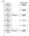
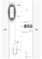
- FIG. 11 is a diagram illustrating an example of the operation of a first recognition unit and a second recognition unit in a certain scene. 11 is a diagram for explaining the processing of a future position prediction/risk setting unit.
- FIG. 1 is a configuration diagram of a vehicle system 1 that uses a recognition device and a control device for a moving object according to an embodiment.
- FIG. 2 is a functional configuration diagram of a first control unit and a second control unit.
- FIG. 2 illustrates an example of a configuration of a recognition unit.
- FIG. 4 is a diagram illustrating an
- the recognition device recognizes at least the position and speed of an object present around the moving body.
- the recognition device is mounted on the moving body, for example, but may be installed outside the moving body.
- the control device for the moving body controls the drive device of the moving body to move the moving body.
- the moving body refers to any object that can move in space using mechanical power, such as a four-wheeled or two-wheeled vehicle, micromobility, or a drone, aircraft, or ship.
- the moving body may move with a person or animal on board, or may be an unmanned moving body. In the following description, the moving body is assumed to be a vehicle that moves on the road with a person on board, and an "automatic driving control device" is taken as an example of a control device.
- [Overall configuration] 1 is a configuration diagram of a vehicle system 1 that uses a recognition device and a mobile object control device according to an embodiment.
- the vehicle on which the vehicle system 1 is mounted is, for example, a two-wheeled, three-wheeled, or four-wheeled vehicle, and its drive source is an internal combustion engine such as a diesel engine or a gasoline engine, an electric motor, or a combination of these.
- the electric motor operates using power generated by a generator connected to the internal combustion engine, or discharged power from a secondary battery or a fuel cell.
- the vehicle system 1 includes, for example, a camera 10, a radar device 12, a LIDAR (Light Detection and Ranging) 14, an object recognition device 16, a communication device 20, an HMI (Human Machine Interface) 30, a vehicle sensor 40, a navigation device 50, an MPU (Map Positioning Unit) 60, a driving operator 80, an automatic driving control device 100, a driving force output device 200, a braking device 210, and a steering device 220.
- These devices and equipment are connected to each other by multiple communication lines such as a CAN (Controller Area Network) communication line, serial communication lines, a wireless communication network, etc.
- CAN Controller Area Network
- the camera 10 is, for example, a digital camera that uses a solid-state imaging element such as a CCD (Charge Coupled Device) or a CMOS (Complementary Metal Oxide Semiconductor).
- the camera 10 is attached at any location of the vehicle (hereinafter, vehicle M) in which the vehicle system 1 is mounted.
- vehicle M vehicle
- the camera 10 is attached to the top of the front windshield, the back of the rearview mirror, or the like.
- the camera 10 for example, periodically and repeatedly captures images of the surroundings of the vehicle M.
- the camera 10 may be a stereo camera.
- the radar device 12 emits radio waves such as millimeter waves around the vehicle M and detects radio waves reflected by objects (reflected waves) to detect at least the position (distance and direction) of the object.
- the radar device 12 is attached to any location on the vehicle M.
- the radar device 12 may detect the position and speed of an object using the FM-CW (Frequency Modulated Continuous Wave) method.
- FM-CW Frequency Modulated Continuous Wave
- the LIDAR 14 irradiates light (or electromagnetic waves with a wavelength close to that of light) around the vehicle M and measures the scattered light.
- the LIDAR 14 detects the distance to the target based on the time between emitting and receiving the light.
- the irradiated light is, for example, a pulsed laser light.
- the LIDAR 14 can be attached to any location on the vehicle M.
- the object recognition device 16 performs sensor fusion processing on the detection results from some or all of the camera 10, radar device 12, and LIDAR 14 to recognize the position, type, speed, etc. of the object.
- the object recognition device 16 outputs the recognition results to the autonomous driving control device 100.
- the object recognition device 16 may output the detection results from the camera 10, radar device 12, and LIDAR 14 directly to the autonomous driving control device 100.
- the object recognition device 16 may be omitted from the vehicle system 1.
- the communication device 20 communicates with other vehicles in the vicinity of the vehicle M using, for example, a cellular network, a Wi-Fi network, Bluetooth (registered trademark), or DSRC (Dedicated Short Range Communication), or communicates with various server devices via a wireless base station.
- a cellular network for example, a Wi-Fi network, Bluetooth (registered trademark), or DSRC (Dedicated Short Range Communication), or communicates with various server devices via a wireless base station.
- the HMI 30 presents various information to the occupants of the vehicle M and accepts input operations by the occupants.
- the HMI 30 includes various display devices, speakers, buzzers, touch panels, switches, keys, etc.
- the vehicle sensor 40 includes a vehicle speed sensor that detects the speed of the vehicle M, an acceleration sensor that detects the acceleration, a yaw rate sensor that detects the angular velocity around the vertical axis, a direction sensor that detects the direction of the vehicle M, etc.
- the navigation device 50 includes, for example, a GNSS (Global Navigation Satellite System) receiver 51, a navigation HMI 52, and a route determination unit 53.
- the navigation device 50 stores first map information 54 in a storage device such as a HDD (Hard Disk Drive) or flash memory.
- the GNSS receiver 51 determines the position of the vehicle M based on signals received from GNSS satellites. The position of the vehicle M may be determined or supplemented by an INS (Inertial Navigation System) that uses the output of the vehicle sensor 40.
- the navigation HMI 52 includes a display device, a speaker, a touch panel, keys, etc. The navigation HMI 52 may be partially or completely shared with the HMI 30 described above.
- the route determination unit 53 determines a route (hereinafter, a route on a map) from the position of the vehicle M specified by the GNSS receiver 51 (or any input position) to a destination input by the occupant using the navigation HMI 52, for example, by referring to the first map information 54.
- the first map information 54 is, for example, information in which a road shape is expressed by links indicating roads and nodes connected by the links.
- the first map information 54 may include road curvature and POI (Point of Interest) information.
- the route on the map is output to the MPU 60.
- the navigation device 50 may perform route guidance using the navigation HMI 52 based on the route on the map.
- the navigation device 50 may be realized by the function of a terminal device such as a smartphone or tablet terminal owned by the occupant.
- the navigation device 50 may transmit the current position and the destination to a navigation server via the communication device 20, and obtain a route equivalent to the route on the map from the navigation server.
- the MPU 60 includes, for example, a recommended lane determination unit 61, and stores second map information 62 in a storage device such as an HDD or flash memory.
- the recommended lane determination unit 61 divides the route on the map provided by the navigation device 50 into a number of blocks (for example, every 100 m in the vehicle travel direction), and determines a recommended lane for each block by referring to the second map information 62.
- the recommended lane determination unit 61 determines, for example, which lane from the left to use. When there is a branch on the route on the map, the recommended lane determination unit 61 determines a recommended lane so that the vehicle M can use a reasonable route to proceed to the branch destination.
- the second map information 62 is map information with higher accuracy than the first map information 54.
- the second map information 62 includes, for example, information on the center of lanes or information on lane boundaries.
- the second map information 62 may also include road information, traffic regulation information, address information (address and postal code), facility information, telephone number information, information on prohibited sections where mode A or mode B described below is prohibited, and the like.
- the second map information 62 may be updated at any time by the communication device 20 communicating with other devices.
- the driving operators 80 include, for example, a steering wheel, an accelerator pedal, a brake pedal, a shift lever, and other operators.
- the driving operators 80 are fitted with sensors that detect the amount of operation or the presence or absence of operation, and the detection results are output to the automatic driving control device 100, or some or all of the driving force output device 200, the brake device 210, and the steering device 220.
- the automatic driving control device 100 includes, for example, a first control unit 120 and a second control unit 160.
- the first control unit 120 and the second control unit 160 are each realized by, for example, a hardware processor such as a CPU (Central Processing Unit) executing a program (software).
- a hardware processor such as a CPU (Central Processing Unit) executing a program (software).
- some or all of these components may be realized by hardware (including circuitry) such as an LSI (Large Scale Integration), ASIC (Application Specific Integrated Circuit), FPGA (Field-Programmable Gate Array), or GPU (Graphics Processing Unit), or may be realized by collaboration between software and hardware.
- LSI Large Scale Integration
- ASIC Application Specific Integrated Circuit
- FPGA Field-Programmable Gate Array
- GPU Graphics Processing Unit
- the program may be stored in advance in a storage device (a storage device with a non-transient storage medium) such as the HDD or flash memory of the autonomous driving control device 100, or may be stored in a removable storage medium such as a DVD or CD-ROM, and installed in the HDD or flash memory of the autonomous driving control device 100 by mounting the storage medium (non-transient storage medium) in a drive device.
- a storage device a storage device with a non-transient storage medium
- a storage device such as the HDD or flash memory of the autonomous driving control device 100
- a removable storage medium such as a DVD or CD-ROM
- the autonomous driving control device 100 is an example of a "vehicle control device”
- the recognition unit 130 is an example of a “recognition device”
- the combination of the action plan generation unit 140 and the second control unit 160 is an example of a "driving control unit”.
- FIG. 2 is a functional configuration diagram of the first control unit 120 and the second control unit 160.
- the first control unit 120 includes, for example, a recognition unit 130, an action plan generation unit 140, and a mode determination unit 150.
- the first control unit 120 realizes, for example, a function based on AI (Artificial Intelligence) and a function based on a pre-given model in parallel.
- AI Artificial Intelligence
- the "intersection recognition" function may be realized by executing in parallel the recognition of the intersection using deep learning or the like and the recognition based on pre-given conditions (such as traffic lights and road markings that can be pattern matched), and by scoring both and evaluating them comprehensively. This ensures the reliability of autonomous driving.
- the recognition unit 130 recognizes the presence, position, and state of the speed, acceleration, etc. of objects around the vehicle M based on information input from the camera 10, the radar device 12, and the LIDAR 14 via the object recognition device 16.
- the position of the object is recognized as a position on an absolute coordinate system with a representative point of the vehicle M (such as the center of gravity or the center of the drive shaft) as the origin, and is used for control.
- the position of the object may be represented by a representative point such as the center of gravity or a corner of the object, or may be represented by an area.
- the "state" of the object may include the acceleration or jerk of the object, or the "behavioral state” (for example, whether or not the object is changing lanes or is about to change lanes).
- the recognition unit 130 also recognizes, for example, the lane in which the vehicle M is traveling (the driving lane). For example, the recognition unit 130 recognizes the driving lane by comparing the pattern of road dividing lines (for example, an arrangement of solid and dashed lines) obtained from the second map information 62 with the pattern of road dividing lines around the vehicle M recognized from the image captured by the camera 10. Note that the recognition unit 130 may recognize the driving lane by recognizing road boundaries (road boundaries) including not only road dividing lines but also road dividing lines, shoulders, curbs, medians, guard rails, etc. In this recognition, the position of the vehicle M obtained from the navigation device 50 and the processing results by the INS may be taken into account. The recognition unit 130 also recognizes stop lines, obstacles, red lights, toll booths, and other road phenomena.
- road boundaries for example, an arrangement of solid and dashed lines
- the recognition unit 130 recognizes the position and attitude of the vehicle M with respect to the driving lane. For example, the recognition unit 130 may recognize the deviation of the reference point of the vehicle M from the center of the lane and the angle with respect to a line connecting the centers of the lanes in the direction of travel of the vehicle M as the relative position and attitude of the vehicle M with respect to the driving lane. Alternatively, the recognition unit 130 may recognize the position of the reference point of the vehicle M with respect to either side end of the driving lane (road division line or road boundary) as the relative position of the vehicle M with respect to the driving lane.
- the action plan generating unit 140 generates a target trajectory for the vehicle M to automatically (without the driver's operation) travel in the future so that, in principle, the vehicle travels in the recommended lane determined by the recommended lane determining unit 61 and avoids approaching objects (excluding road division lines, road markings, manholes, and other objects that can be climbed over) recognized by the recognition unit 130.
- the recognition unit 130 sets a risk area centered on the object whose state has been output, and within the risk area, the recognition unit 130 sets a risk as an index value indicating the degree to which the vehicle M should not approach.
- the action plan generating unit 140 generates a target trajectory so that the vehicle M does not pass through a point where the risk is equal to or greater than a predetermined value.
- the target trajectory includes, for example, a speed element.
- the target trajectory is expressed as a sequence of points (trajectory points) to be reached by the vehicle M.
- a trajectory point is a point where the vehicle M should reach at each predetermined travel distance (e.g., about several meters) along a road, and separately, a target speed and target acceleration are generated as part of the target trajectory for each predetermined sampling time (e.g., about a few tenths of a second).
- a trajectory point may also be a position where the vehicle M should reach at each predetermined sampling time.
- the information on the target speed and target acceleration is expressed as the interval between trajectory points.
- the second control unit 160 controls the driving force output device 200, the brake device 210, and the steering device 220 so that the vehicle M passes through the target trajectory generated by the action plan generation unit 140 at the scheduled time.
- the second control unit 160 includes, for example, an acquisition unit 162, a speed control unit 164, and a steering control unit 166.
- the acquisition unit 162 acquires information on the target trajectory (trajectory points) generated by the action plan generation unit 140, and stores it in a memory (not shown).
- the speed control unit 164 controls the driving force output device 200 or the brake device 210 based on the speed element associated with the target trajectory stored in the memory.
- the steering control unit 166 controls the steering device 220 according to the curvature of the target trajectory stored in the memory.
- the processing of the speed control unit 164 and the steering control unit 166 is realized, for example, by a combination of feedforward control and feedback control.
- the steering control unit 166 executes a combination of feedforward control according to the curvature of the road ahead of the vehicle M and feedback control based on the deviation from the target trajectory.
- the driving force output device 200 outputs a driving force (torque) to the drive wheels for the vehicle to travel.
- the driving force output device 200 comprises, for example, a combination of an internal combustion engine, an electric motor, and a transmission, and an ECU (Electronic Control Unit) that controls these.
- the ECU controls the above configuration according to information input from the second control unit 160 or information input from the driving operator 80.
- the brake device 210 includes, for example, a brake caliper, a cylinder that transmits hydraulic pressure to the brake caliper, an electric motor that generates hydraulic pressure in the cylinder, and a brake ECU.
- the brake ECU controls the electric motor according to information input from the second control unit 160 or information input from the driving operator 80, so that a brake torque corresponding to the braking operation is output to each wheel.
- the brake device 210 may include a backup mechanism that transmits hydraulic pressure generated by operating the brake pedal included in the driving operator 80 to the cylinder via a master cylinder. Note that the brake device 210 is not limited to the configuration described above, and may be an electronically controlled hydraulic brake device that controls an actuator according to information input from the second control unit 160 to transmit hydraulic pressure from the master cylinder to the cylinder.
- the steering device 220 includes, for example, a steering ECU and an electric motor.
- the electric motor changes the direction of the steered wheels by, for example, applying a force to a rack and pinion mechanism.
- the steering ECU drives the electric motor according to information input from the second control unit 160 or information input from the driving operator 80, to change the direction of the steered wheels.
- Fig. 3 is a diagram showing an example of the configuration of the recognition unit 130.
- the recognition unit 130 includes, for example, a first recognition unit 132, a second recognition unit 134, a fusion unit 136, and a future position prediction/risk setting unit 138.
- the first recognition unit 132 repeatedly outputs the object's position, which is the result of processing to recognize the object's position, in a first period.
- the second recognition unit 134 repeatedly outputs the object's speed, which is the result of processing to recognize the object's speed, in a second period shorter than the first period. In other words, the second recognition unit 134 performs processing at a higher speed than the first recognition unit 132. For example, the second recognition unit 134 performs processing at a frequency several times to several tens of times higher than the first recognition unit 132.
- the second recognition unit 134 has a function of provisionally recognizing the presence and position of an object whose position has not been output by the first recognition unit 132. There are no particular restrictions on this function, and it is sufficient that it is a process that is simpler and has a lower load than the process performed by the first recognition unit 132. As an example, this function is realized by a process that combines a contour extraction process and a size recognition process. This function may be stopped when the first recognition unit 132 starts to output the position, or may be continued even after the first recognition unit 132 starts to output the position.
- the fusion unit 136 When the first recognition unit 132 outputs a position and the second recognition unit 134 outputs a speed (and position), the fusion unit 136 outputs the position output by the first recognition unit 132 and the speed output by the second recognition unit 134 as the state of the object.
- the first recognition unit 132 does not output a position, but the second recognition unit 134 outputs a position (provisionally recognized as described above) and speed, the fusion unit 136 outputs the position and speed output by the second recognition unit 134 as the state of the object.
- the first recognition unit 132 and the second recognition unit 134 each perform processing by executing at least a part of a common processing procedure.
- the first recognition unit 132 and the second recognition unit 134 each input an image captured by the camera 10 (or an image that has been preprocessed) into a learned model such as a DNN (Deep Neural Network) to recognize and output the position, speed, etc. of an object, and the second recognition unit 134 compresses the input image to a lower resolution than the image input to the first recognition unit 132, thereby performing processing faster than the first recognition unit 132.
- Figure 4 is a diagram showing an example of the relationship between the first recognition unit 132 and the second recognition unit 134. In this case, the input image input to the first recognition unit 132 is thinned out in time, resulting in a smaller number of frames than the input image input to the second recognition unit 134.
- FIG. 5 is a diagram showing an example of the operation of the first recognition unit 132 and the second recognition unit 134 in a certain scene.
- the second recognition unit 134 performs processing at a frequency three times that of the first recognition unit 132.
- the control timing is a virtual time that arrives at a predetermined period (which is the same as the processing period of the second recognition unit 134 in this embodiment).
- a predetermined period which is the same as the processing period of the second recognition unit 134 in this embodiment.
- the control timing is assumed to start from 1.
- the second recognition unit 134 provisionally recognizes the presence and position of the object for the first time.
- the second recognition unit 134 also recognizes the speed of the object.
- the first recognition unit 132 or the second recognition unit 134 (or another functional unit) predicts the position and speed of the object at the next control timing 2, for example, by calculating a covariance matrix generated by arranging the states calculated before that control timing, its eigenvalues, and an interpolated value for future expansion (next prediction). This next prediction process is repeatedly executed at each control timing.
- the state output by the recognition unit 130 is defined as an object whose position has been provisionally recognized and whose speed has been definitively recognized.
- the degree of control over the object is changed depending on whether it has been provisionally recognized or definitively recognized. For example, for an object whose position has been provisionally recognized, the risk is calculated to be smaller than for an object whose position has been definitively recognized, and the degree of control is relaxed.
- the second recognition unit 134 updates the object's position and speed based on the result of the next prediction at control timing 1 and the result of processing the input image.
- the first recognition unit 132 updates the object's position based on the result of the next prediction at control timing 2 and the result of processing the input image.
- the second recognition unit 134 updates the object's speed based on the result of the next prediction at control timing 2 and the result of processing the input image. At this point, it is defined that the presence of the object is confirmed, and the object's position is also confirmed to be recognized definitively.
- the second recognition unit 134 updates the object's speed based on the result of the next prediction at control timing 3 and the result of processing the input image.
- the second recognition unit 134 updates the object's speed based on the result of the next prediction at control timing 4 and the result of processing the input image.
- the first recognition unit 132 updates the object's position based on the result of the next prediction at control timing 5 and the result of processing the input image.
- the second recognition unit 134 updates the object's speed based on the result of the next prediction at control timing 5 and the result of processing the input image. After that, the same processing as at control timings 4 to 6 is repeatedly executed.
- the future position prediction/risk setting unit 138 predicts the future position of the object based on the state (position, speed) of the object output by the fusion unit 136, and sets a risk for the object.
- FIG. 6 is a diagram for explaining the processing of the future position prediction/risk setting unit 138.
- the future position prediction/risk setting unit 138 sets risk, which is an index value indicating the degree to which the vehicle M should not enter or approach, on the assumed plane S, which is a virtual plane that represents the space around the vehicle M as a two-dimensional plane viewed from above. The higher the risk value, the more likely the vehicle M should not enter or approach, and the closer the value is to zero, the more favorable it is for the vehicle M to travel. However, this relationship may be reversed. If the moving object is a flying object such as a drone rather than a vehicle, the future position prediction/risk setting unit 138 may perform similar processing in three-dimensional space rather than on the assumed plane S.
- the future position prediction/risk setting unit 138 sets the risk on the imaginary plane S not only for the current time, but also for the future positions of objects predicted in advance and specified at regular time intervals, such as the current time t, ⁇ t later (time t + ⁇ t), 2 ⁇ t later (time t + 2 ⁇ t), etc.
- the future position prediction/risk setting unit 138 sets the risk of vehicles, pedestrians, bicycles, and other traffic participants (moving targets) on the assumed plane S, with ellipses or circles based on the direction of travel and speed as contour lines, and sets a fixed value of risk for impassable areas.
- DM is the direction of travel of vehicle M.
- R(M1) is the risk of stopped vehicle M1
- R(P) is the risk of pedestrian P. Since pedestrian P is moving in a direction crossing the road, a risk is set at a position different from the current time for each future point in time. The same applies to moving vehicles, bicycles, and the like.
- R(BD) is the risk of impassable areas BD. In the figure, the darkness of the hatching indicates the risk value, and the darker the hatching, the greater the risk.
- the future position prediction/risk setting unit 138 may set the risk so that the value increases the further away from the center of the lane.
- the recognition unit 130 and the automatic driving control device 100 can quickly follow the speed change of the object.
- the second recognition unit 134 performs processing using a compressed input image, so the overall processing time can be shortened, and processing can be performed faster than the first recognition unit 132, which performs processing using a high-resolution image.
- the advantage of processing using a high-resolution image is that it can accurately detect objects that are mainly far away from the vehicle M, but it is known that there is not much performance difference for objects that are close to the vehicle M.
- the second recognition unit 134 which mainly recognizes the speed, processes at a high speed, so sudden changes in the speed of the object can be detected quickly. Therefore, it is possible to quickly follow the speed change of the object, and ultimately to quickly control the behavior of the vehicle M.
- Each of the first recognition unit 132 and the second recognition unit 134 is realized, for example, by one or more processors performing processing as the first recognition unit 132 and processing as the second recognition unit 134 in a time-division manner. The same may be true for the fusion unit 136 and the future position prediction/risk setting unit 138. Alternatively, each of the first recognition unit 132 and the second recognition unit 134 may be realized by separate processors performing processing. The same may be true for the fusion unit 136 and the future position prediction/risk setting unit 138.
- control device is described as being mounted on the vehicle M (i.e., the moving body), but this is not limited thereto.
- the control device may be installed at a location away from the moving body, and may acquire output data from the camera 10, radar device 12, etc., via communication, and may transmit a drive command signal to the moving body, i.e., may remotely control the moving body.
- a recognition device that recognizes a position and a speed of an object present around a moving body based on an output of a detection device for detecting a surrounding situation of the moving body, one or more storage media storing computer-readable instructions; a processor coupled to the one or more storage media; The processor executes the computer-readable instructions to: repeatedly outputting the position of the object, which is a result of performing processing for recognizing the position of the object, in a first period; repeatedly outputting the velocity of the object, which is a result of performing a process for recognizing the velocity of the object, at a second period shorter than the first period; Control device.
Landscapes
- Engineering & Computer Science (AREA)
- Automation & Control Theory (AREA)
- Transportation (AREA)
- Mechanical Engineering (AREA)
- Physics & Mathematics (AREA)
- General Physics & Mathematics (AREA)
- Traffic Control Systems (AREA)
Abstract
移動体の周辺状況を検知するための検知デバイスの出力に基づいて、前記移動体の周辺に存在する物体の位置および速度を認識する認識装置であって、前記物体の位置を認識するための処理を行った結果である前記物体の位置を第1周期で繰り返し出力する第1認識部と、前記物体の速度を認識するための処理を行った結果である前記物体の速度を前記第1周期よりも短い第2周期で繰り返し出力する第2認識部と、を備える認識装置。
Description
本発明は、認識装置、移動体の制御装置、認識方法、およびプログラムに関する。
近年、車両などの移動体を自律的に移動させることについて研究および実用化が進められている。係る技術において、殆どの場合、移動体の周辺に存在する物体を認識する技術(以下、周辺認識技術)が必要不可欠である。周辺認識技術に関するものとして、車両の現在所在の運転シーンにおける運転シーンデータと運転行為データに基づいて、所定の安定走行条件を満たしているか否かを確定し、所定の安定走行条件を満たしている場合に、所定のサンプリング周波数よりも低い周波数で運転シーンデータと運転行為データを採集することにより、類似のシーン、類似の運転モードにおけるデータの冗長を低減する発明が開示されている(特許文献1)。
周辺認識技術を実現する上で、プロセッサの負荷を低減することと、急な事象の発生に速やかに追従することを両立しなければならない。上記従来の技術では、移動体の環境を総合的に判断する反面、局所的な変化に速やかに追従することができないことが懸念される。具体的には、従来の技術では、物体の速度変化に速やかに追従することができない場合があり得る。
本発明は、このような事情を考慮してなされたものであり、物体の速度変化に速やかに追従することができる認識装置、移動体の制御装置、認識方法、およびプログラムを提供することを目的の一つとする。
この発明に係る認識装置、移動体の制御装置、認識方法、およびプログラムは、以下の構成を採用した。
(1):この発明の一態様に係る認識装置は、移動体の周辺状況を検知するための検知デバイスの出力に基づいて、前記移動体の周辺に存在する物体の位置および速度を認識する認識装置であって、前記物体の位置を認識するための処理を行った結果である前記物体の位置を第1周期で繰り返し出力する第1認識部と、前記物体の速度を認識するための処理を行った結果である前記物体の速度を前記第1周期よりも短い第2周期で繰り返し出力する第2認識部と、を備えるものである。
(1):この発明の一態様に係る認識装置は、移動体の周辺状況を検知するための検知デバイスの出力に基づいて、前記移動体の周辺に存在する物体の位置および速度を認識する認識装置であって、前記物体の位置を認識するための処理を行った結果である前記物体の位置を第1周期で繰り返し出力する第1認識部と、前記物体の速度を認識するための処理を行った結果である前記物体の速度を前記第1周期よりも短い第2周期で繰り返し出力する第2認識部と、を備えるものである。
(2):上記(1)の態様において、前記第2認識部は、前記第1認識部により位置が出力されていない物体の位置を暫定的に認識する機能を有し、前記第1認識部から位置が、前記第2認識部から速度が、それぞれ出力されている場合、前記第1認識部が出力した位置と前記第2認識部が出力した速度を当該物体の状態として出力し、前記第1認識部から位置が出力されておらず、前記第2認識部から位置および速度が出力されている物体について、前記第2認識部が出力した位置および速度を当該物体の状態として出力するフュージョン部を更に備えるものである。
(3):上記(2)の態様において、前記第2認識部は、前記第1認識部により位置が出力されていない物体の存在を認識する機能を有するものである。
(4):上記(1)の態様において、前記第1認識部と前記第2認識部は、少なくとも一部が共通する処理手順を実行することで、それぞれ処理を行うものである。
(5):上記(1)の態様において、前記第1認識部と前記第2認識部のそれぞれは、一または複数のプロセッサが、前記第1認識部としての処理と前記第2認識部としての処理を時分割で行うことで実現されるものである。
(6):上記(1)の態様において、前記第1認識部と前記第2認識部のそれぞれは、別体のプロセッサが処理を行うことで実現されるものである。
(7):本発明の他の態様に係る移動体の制御装置は、上記(1)の態様の認識装置と、前記認識装置が状態を出力した物体への接近を回避するように前記移動体を移動させる運転制御部と、を備えるものである。
(8):本発明の他の態様に係る認識方法は、移動体の周辺状況を検知するための検知デバイスの出力に基づいて、前記移動体の周辺に存在する物体の位置および速度を認識する認識装置を用いて実行される認識方法であって、前記物体の位置を認識するための処理を行った結果である前記物体の位置を第1周期で繰り返し出力することと、前記物体の速度を認識するための処理を行った結果である前記物体の速度を前記第1周期よりも短い第2周期で繰り返し出力することと、を備えるものである。
(9):本発明の他の態様に係るプログラムは、移動体の周辺状況を検知するための検知デバイスの出力に基づいて、前記移動体の周辺に存在する物体の位置および速度を認識する認識装置のプロセッサに、前記物体の位置を認識するための処理を行った結果である前記物体の位置を第1周期で繰り返し出力することと、前記物体の速度を認識するための処理を行った結果である前記物体の速度を前記第1周期よりも短い第2周期で繰り返し出力することと、を実行させるためのプログラムである。
(1)~(9)の態様によれば、物体の速度変化に速やかに追従することができる。
[概要]
以下、図面を参照し、本発明の認識装置、移動体の制御装置、認識方法、およびプログラムの実施形態について説明する。認識装置は、移動体の周辺に存在する物体の少なくとも位置および速度を認識する。認識装置は、例えば移動体に搭載されるものであるが、移動体の外部に設置されてもよい。移動体の制御装置は、移動体の駆動装置を制御して移動体を移動させるものである。移動体とは、四輪や二輪などの車両、マイクロモビリティ、或いはドローンや航空機、船舶など、機械的動力を用いて空間を移動可能なあらゆるものを指す。移動体は人や動物を搭載して移動するものでもよいし、無人で移動するものでもよい。以下の説明では、移動体は人を搭載して路上を移動する車両であるものとし、制御装置の一例として「自動運転制御装置」を例に挙げて説明する。
以下、図面を参照し、本発明の認識装置、移動体の制御装置、認識方法、およびプログラムの実施形態について説明する。認識装置は、移動体の周辺に存在する物体の少なくとも位置および速度を認識する。認識装置は、例えば移動体に搭載されるものであるが、移動体の外部に設置されてもよい。移動体の制御装置は、移動体の駆動装置を制御して移動体を移動させるものである。移動体とは、四輪や二輪などの車両、マイクロモビリティ、或いはドローンや航空機、船舶など、機械的動力を用いて空間を移動可能なあらゆるものを指す。移動体は人や動物を搭載して移動するものでもよいし、無人で移動するものでもよい。以下の説明では、移動体は人を搭載して路上を移動する車両であるものとし、制御装置の一例として「自動運転制御装置」を例に挙げて説明する。
[全体構成]
図1は、実施形態に係る認識装置および移動体の制御装置を利用した車両システム1の構成図である。車両システム1が搭載される車両は、例えば、二輪や三輪、四輪等の車両であり、その駆動源は、ディーゼルエンジンやガソリンエンジンなどの内燃機関、電動機、或いはこれらの組み合わせである。電動機は、内燃機関に連結された発電機による発電電力、或いは二次電池や燃料電池の放電電力を使用して動作する。
図1は、実施形態に係る認識装置および移動体の制御装置を利用した車両システム1の構成図である。車両システム1が搭載される車両は、例えば、二輪や三輪、四輪等の車両であり、その駆動源は、ディーゼルエンジンやガソリンエンジンなどの内燃機関、電動機、或いはこれらの組み合わせである。電動機は、内燃機関に連結された発電機による発電電力、或いは二次電池や燃料電池の放電電力を使用して動作する。
車両システム1は、例えば、カメラ10と、レーダ装置12と、LIDAR(Light Detection and Ranging)14と、物体認識装置16と、通信装置20と、HMI(Human Machine Interface)30と、車両センサ40と、ナビゲーション装置50と、MPU(Map Positioning Unit)60と、運転操作子80と、自動運転制御装置100と、走行駆動力出力装置200と、ブレーキ装置210と、ステアリング装置220とを備える。これらの装置や機器は、CAN(Controller Area Network)通信線等の多重通信線やシリアル通信線、無線通信網等によって互いに接続される。なお、図1に示す構成はあくまで一例であり、構成の一部が省略されてもよいし、更に別の構成が追加されてもよい。
カメラ10は、例えば、CCD(Charge Coupled Device)やCMOS(Complementary Metal Oxide Semiconductor)等の固体撮像素子を利用したデジタルカメラである。カメラ10は、車両システム1が搭載される車両(以下、車両M)の任意の箇所に取り付けられる。前方を撮像する場合、カメラ10は、フロントウインドシールド上部やルームミラー裏面等に取り付けられる。カメラ10は、例えば、周期的に繰り返し車両Mの周辺を撮像する。カメラ10は、ステレオカメラであってもよい。
レーダ装置12は、車両Mの周辺にミリ波などの電波を放射すると共に、物体によって反射された電波(反射波)を検出して少なくとも物体の位置(距離および方位)を検出する。レーダ装置12は、車両Mの任意の箇所に取り付けられる。レーダ装置12は、FM-CW(Frequency Modulated Continuous Wave)方式によって物体の位置および速度を検出してもよい。
LIDAR14は、車両Mの周辺に光(或いは光に近い波長の電磁波)を照射し、散乱光を測定する。LIDAR14は、発光から受光までの時間に基づいて、対象までの距離を検出する。照射される光は、例えば、パルス状のレーザー光である。LIDAR14は、車両Mの任意の箇所に取り付けられる。
物体認識装置16は、カメラ10、レーダ装置12、およびLIDAR14のうち一部または全部による検出結果に対してセンサフュージョン処理を行って、物体の位置、種類、速度などを認識する。物体認識装置16は、認識結果を自動運転制御装置100に出力する。物体認識装置16は、カメラ10、レーダ装置12、およびLIDAR14の検出結果をそのまま自動運転制御装置100に出力してよい。車両システム1から物体認識装置16が省略されてもよい。
通信装置20は、例えば、セルラー網やWi-Fi網、Bluetooth(登録商標)、DSRC(Dedicated Short Range Communication)などを利用して、車両Mの周辺に存在する他車両と通信し、或いは無線基地局を介して各種サーバ装置と通信する。
HMI30は、車両Mの乗員に対して各種情報を提示すると共に、乗員による入力操作を受け付ける。HMI30は、各種表示装置、スピーカ、ブザー、タッチパネル、スイッチ、キーなどを含む。
車両センサ40は、車両Mの速度を検出する車速センサ、加速度を検出する加速度センサ、鉛直軸回りの角速度を検出するヨーレートセンサ、車両Mの向きを検出する方位センサ等を含む。
ナビゲーション装置50は、例えば、GNSS(Global Navigation Satellite System)受信機51と、ナビHMI52と、経路決定部53とを備える。ナビゲーション装置50は、HDD(Hard Disk Drive)やフラッシュメモリなどの記憶装置に第1地図情報54を保持している。GNSS受信機51は、GNSS衛星から受信した信号に基づいて、車両Mの位置を特定する。車両Mの位置は、車両センサ40の出力を利用したINS(Inertial Navigation System)によって特定または補完されてもよい。ナビHMI52は、表示装置、スピーカ、タッチパネル、キーなどを含む。ナビHMI52は、前述したHMI30と一部または全部が共通化されてもよい。経路決定部53は、例えば、GNSS受信機51により特定された車両Mの位置(或いは入力された任意の位置)から、ナビHMI52を用いて乗員により入力された目的地までの経路(以下、地図上経路)を、第1地図情報54を参照して決定する。第1地図情報54は、例えば、道路を示すリンクと、リンクによって接続されたノードとによって道路形状が表現された情報である。第1地図情報54は、道路の曲率やPOI(Point Of Interest)情報などを含んでもよい。地図上経路は、MPU60に出力される。ナビゲーション装置50は、地図上経路に基づいて、ナビHMI52を用いた経路案内を行ってもよい。ナビゲーション装置50は、例えば、乗員の保有するスマートフォンやタブレット端末等の端末装置の機能によって実現されてもよい。ナビゲーション装置50は、通信装置20を介してナビゲーションサーバに現在位置と目的地を送信し、ナビゲーションサーバから地図上経路と同等の経路を取得してもよい。
MPU60は、例えば、推奨車線決定部61を含み、HDDやフラッシュメモリなどの記憶装置に第2地図情報62を保持している。推奨車線決定部61は、ナビゲーション装置50から提供された地図上経路を複数のブロックに分割し(例えば、車両進行方向に関して100[m]毎に分割し)、第2地図情報62を参照してブロックごとに推奨車線を決定する。推奨車線決定部61は、左から何番目の車線を走行するといった決定を行う。推奨車線決定部61は、地図上経路に分岐箇所が存在する場合、車両Mが、分岐先に進行するための合理的な経路を走行できるように、推奨車線を決定する。
第2地図情報62は、第1地図情報54よりも高精度な地図情報である。第2地図情報62は、例えば、車線の中央の情報あるいは車線の境界の情報等を含んでいる。また、第2地図情報62には、道路情報、交通規制情報、住所情報(住所・郵便番号)、施設情報、電話番号情報、後述するモードAまたはモードBが禁止される禁止区間の情報などが含まれてよい。第2地図情報62は、通信装置20が他装置と通信することにより、随時、アップデートされてよい。
運転操作子80は、例えば、ステアリングホイール、アクセルペダル、ブレーキペダル、シフトレバー、その他の操作子を含む。運転操作子80には、操作量あるいは操作の有無を検出するセンサが取り付けられており、その検出結果は、自動運転制御装置100、もしくは、走行駆動力出力装置200、ブレーキ装置210、およびステアリング装置220のうち一部または全部に出力される。
自動運転制御装置100は、例えば、第1制御部120と、第2制御部160とを備える。第1制御部120と第2制御部160は、それぞれ、例えば、CPU(Central Processing Unit)などのハードウェアプロセッサがプログラム(ソフトウェア)を実行することにより実現される。また、これらの構成要素のうち一部または全部は、LSI(Large Scale Integration)やASIC(Application Specific Integrated Circuit)、FPGA(Field-Programmable Gate Array)、GPU(Graphics Processing Unit)などのハードウェア(回路部;circuitryを含む)によって実現されてもよいし、ソフトウェアとハードウェアの協働によって実現されてもよい。プログラムは、予め自動運転制御装置100のHDDやフラッシュメモリなどの記憶装置(非一過性の記憶媒体を備える記憶装置)に格納されていてもよいし、DVDやCD-ROMなどの着脱可能な記憶媒体に格納されており、記憶媒体(非一過性の記憶媒体)がドライブ装置に装着されることで自動運転制御装置100のHDDやフラッシュメモリにインストールされてもよい。
自動運転制御装置100は「移動体の制御装置」の一例であり、認識部130は「認識装置」の一例であり、行動計画生成部140と第2制御部160を合わせたものが「運転制御部」の一例である。
図2は、第1制御部120および第2制御部160の機能構成図である。第1制御部120は、例えば、認識部130と、行動計画生成部140と、モード決定部150とを備える。第1制御部120は、例えば、AI(Artificial Intelligence;人工知能)による機能と、予め与えられたモデルによる機能とを並行して実現する。例えば、「交差点を認識する」機能は、ディープラーニング等による交差点の認識と、予め与えられた条件(パターンマッチング可能な信号、道路標示などがある)に基づく認識とが並行して実行され、双方に対してスコア付けして総合的に評価することで実現されてよい。これによって、自動運転の信頼性が担保される。
認識部130は、カメラ10、レーダ装置12、およびLIDAR14から物体認識装置16を介して入力された情報に基づいて、車両Mの周辺にある物体の存在、位置、および速度、加速度等の状態を認識する。物体の位置は、例えば、車両Mの代表点(重心や駆動軸中心など)を原点とした絶対座標上の位置として認識され、制御に使用される。物体の位置は、その物体の重心やコーナー等の代表点で表されてもよいし、領域で表されてもよい。物体の「状態」とは、物体の加速度やジャーク、あるいは「行動状態」(例えば車線変更をしている、またはしようとしているか否か)を含んでもよい。
また、認識部130は、例えば、車両Mが走行している車線(走行車線)を認識する。例えば、認識部130は、第2地図情報62から得られる道路区画線のパターン(例えば実線と破線の配列)と、カメラ10によって撮像された画像から認識される車両Mの周辺の道路区画線のパターンとを比較することで、走行車線を認識する。なお、認識部130は、道路区画線に限らず、道路区画線や路肩、縁石、中央分離帯、ガードレールなどを含む走路境界(道路境界)を認識することで、走行車線を認識してもよい。この認識において、ナビゲーション装置50から取得される車両Mの位置やINSによる処理結果が加味されてもよい。また、認識部130は、一時停止線、障害物、赤信号、料金所、その他の道路事象を認識する。
認識部130は、走行車線を認識する際に、走行車線に対する車両Mの位置や姿勢を認識する。認識部130は、例えば、車両Mの基準点の車線中央からの乖離、および車両Mの進行方向の車線中央を連ねた線に対してなす角度を、走行車線に対する車両Mの相対位置および姿勢として認識してもよい。これに代えて、認識部130は、走行車線のいずれかの側端部(道路区画線または道路境界)に対する車両Mの基準点の位置などを、走行車線に対する車両Mの相対位置として認識してもよい。
行動計画生成部140は、原則的には推奨車線決定部61により決定された推奨車線を走行し、更に、認識部130により認識された物体(道路区画線、道路標示、マンホールなどの乗り越え可能なものを除く)への接近を回避するように、車両Mが自動的に(運転者の操作に依らずに)将来走行する目標軌道を生成する。例えば、認識部130は、状態を出力した物体を中心としたリスク領域を設定し、リスク領域内では認識部130により、車両Mが接近すべきでない度合いを示す指標値としてリスクが設定されている。行動計画生成部140は、リスクが所定値以上の地点を通過しないように目標軌道を生成する。物体には移動するものが含まれるため、リスクの分布は制御サイクルごとに一つでは無く、物体の速度に基づいて予測された物体の将来の位置を考慮し、将来の複数時点について設定されるものである。目標軌道は、例えば、速度要素を含んでいる。例えば、目標軌道は、車両Mの到達すべき地点(軌道点)を順に並べたものとして表現される。軌道点は、道なり距離で所定の走行距離(例えば数[m]程度)ごとの車両Mの到達すべき地点であり、それとは別に、所定のサンプリング時間(例えば0コンマ数[sec]程度)ごとの目標速度および目標加速度が、目標軌道の一部として生成される。また、軌道点は、所定のサンプリング時間ごとの、そのサンプリング時刻における車両Mの到達すべき位置であってもよい。この場合、目標速度や目標加速度の情報は軌道点の間隔で表現される。
第2制御部160は、行動計画生成部140によって生成された目標軌道を、予定の時刻通りに車両Mが通過するように、走行駆動力出力装置200、ブレーキ装置210、およびステアリング装置220を制御する。
第2制御部160は、例えば、取得部162と、速度制御部164と、操舵制御部166とを備える。取得部162は、行動計画生成部140により生成された目標軌道(軌道点)の情報を取得し、メモリ(不図示)に記憶させる。速度制御部164は、メモリに記憶された目標軌道に付随する速度要素に基づいて、走行駆動力出力装置200またはブレーキ装置210を制御する。操舵制御部166は、メモリに記憶された目標軌道の曲がり具合に応じて、ステアリング装置220を制御する。速度制御部164および操舵制御部166の処理は、例えば、フィードフォワード制御とフィードバック制御との組み合わせにより実現される。一例として、操舵制御部166は、車両Mの前方の道路の曲率に応じたフィードフォワード制御と、目標軌道からの乖離に基づくフィードバック制御とを組み合わせて実行する。
走行駆動力出力装置200は、車両が走行するための走行駆動力(トルク)を駆動輪に出力する。走行駆動力出力装置200は、例えば、内燃機関、電動機、および変速機などの組み合わせと、これらを制御するECU(Electronic Control Unit)とを備える。ECUは、第2制御部160から入力される情報、或いは運転操作子80から入力される情報に従って、上記の構成を制御する。
ブレーキ装置210は、例えば、ブレーキキャリパーと、ブレーキキャリパーに油圧を伝達するシリンダと、シリンダに油圧を発生させる電動モータと、ブレーキECUとを備える。ブレーキECUは、第2制御部160から入力される情報、或いは運転操作子80から入力される情報に従って電動モータを制御し、制動操作に応じたブレーキトルクが各車輪に出力されるようにする。ブレーキ装置210は、運転操作子80に含まれるブレーキペダルの操作によって発生させた油圧を、マスターシリンダを介してシリンダに伝達する機構をバックアップとして備えてよい。なお、ブレーキ装置210は、上記説明した構成に限らず、第2制御部160から入力される情報に従ってアクチュエータを制御して、マスターシリンダの油圧をシリンダに伝達する電子制御式油圧ブレーキ装置であってもよい。
ステアリング装置220は、例えば、ステアリングECUと、電動モータとを備える。電動モータは、例えば、ラックアンドピニオン機構に力を作用させて転舵輪の向きを変更する。ステアリングECUは、第2制御部160から入力される情報、或いは運転操作子80から入力される情報に従って、電動モータを駆動し、転舵輪の向きを変更させる。
[認識部の更に詳細な構成について]
ここで、認識部130の更に詳細な構成について説明する。上記の機能を実現するために、認識部130は以下に説明するような構成を有する。図3は、認識部130の構成の一例を示す図である。認識部130は、例えば、第1認識部132と、第2認識部134と、フュージョン部136と、将来位置予測/リスク設定部138とを備える。
ここで、認識部130の更に詳細な構成について説明する。上記の機能を実現するために、認識部130は以下に説明するような構成を有する。図3は、認識部130の構成の一例を示す図である。認識部130は、例えば、第1認識部132と、第2認識部134と、フュージョン部136と、将来位置予測/リスク設定部138とを備える。
第1認識部132は、物体の位置を認識するための処理を行った結果である物体の位置を第1周期で繰り返し出力する。
第2認識部134は、物体の速度を認識するための処理を行った結果である物体の速度を、第1周期よりも短い第2周期で繰り返し出力する。つまり、第2認識部134は第1認識部132よりも高速で処理を行う。例えば、第2認識部134は第1認識部132よりも数倍~十数倍程度の周波数で処理を行う。第2認識部134は、第1認識部132により位置が出力されていない物体の存在および位置を暫定的に認識する機能を有する。係る機能については特段の制約は無く、第1認識部132が行う処理よりも簡易かつ低負荷な処理であればよい。一例として、輪郭抽出処理とサイズ認識処理を組み合わせた処理によって、係る機能が実現される。係る機能は、第1認識部132により位置が出力され始めると停止されてもよいし、第1認識部132により位置が出力され始めた後も継続されてもよい。
フュージョン部136は、第1認識部132から位置が、第2認識部134から速度(および位置)が、それぞれ出力されている場合、第1認識部132が出力した位置と第2認識部134が出力した速度を当該物体の状態として出力し、第1認識部132から位置が出力されておらず、第2認識部134から位置(上記の通り暫定的に認識されたもの)および速度が出力されている物体について、第2認識部134が出力した位置および速度を当該物体の状態として出力する。
第1認識部132と第2認識部134は、少なくとも一部が共通する処理手順を実行することで、それぞれ処理を行うものである。例えば、第1認識部132と第2認識部134は、それぞれDNN(Deep Neural Network)などの学習済モデルにカメラ10が撮像した画像(或いはそれに前処理を行った画像)を入力することで物体の位置、速度などを認識して出力するものであり、第2認識部134は、入力される画像を、第1認識部132に入力される画像よりも低解像度に圧縮することで、結果として第1認識部132よりも高速に処理を行うものである。図4は、第1認識部132と第2認識部134の関係の一例を示す図である。なお、この場合、第1認識部132に入力される入力画像は、時間的に間引かれることで、第2認識部134に入力される入力画像よりもフレーム数が少なくなる。
図5は、ある場面における第1認識部132と第2認識部134の動作の一例を示す図である。本図において第2認識部134は、第1認識部132の3倍の周波数で処理を行うものとする。制御タイミングとは、所定周期(本実施例においては第2認識部134の処理周期と同じである)ごとに到来する仮想的な時刻である。制御タイミングごとに、カメラ10の撮像した画像が繰り返し入力される。本図では便宜上、制御タイミングが1から開始されるものとした。
制御タイミング1において、第2認識部134が初めて物体の存在および位置を暫定的に認識する。第2認識部134は、合わせて物体の速度も認識する。このとき、第1認識部132または第2認識部134が(或いは他の機能部が)、次回の制御タイミング2における物体の位置および速度を、例えば当該回の制御タイミング以前に算出された状態を並べて生成した共分散行列、その固有値、および将来に展開するための補間値を計算することで予測しておく(次回予測)。この次回予測の処理は制御タイミングごとに繰り返し実行される。
制御タイミング1において、認識部130の出力する状態の定義は、物体の位置については暫定認識、速度については確定的に認識されたと定義される。暫定認識であるか、確定的に認識されたかによって、その物体に対する制御の度合いが変更される。例えば、位置が暫定認識された物体については、位置が確定的に認識された物体に比してリスクを小さく計算することで、制御の度合いを緩めるといった処理が行われる。
制御タイミング2において、第2認識部134が制御タイミング1における次回予測の結果と、入力された画像を処理した結果とに基づいて、物体の位置と速度を更新する。
制御タイミング3において、第1認識部132が制御タイミング2における次回予測の結果と、入力された画像を処理した結果とに基づいて、物体の位置を更新する。また、第2認識部134が制御タイミング2における次回予測の結果と、入力された画像を処理した結果とに基づいて、物体の速度を更新する。このとき、物体の存在が確定し、物体の位置に関しても確定的に認識されたと定義される。
制御タイミング4において、第2認識部134が制御タイミング3における次回予測の結果と、入力された画像を処理した結果とに基づいて、物体の速度を更新する。
制御タイミング5において、第2認識部134が制御タイミング4における次回予測の結果と、入力された画像を処理した結果とに基づいて、物体の速度を更新する。
制御タイミング6において、第1認識部132が制御タイミング5における次回予測の結果と、入力された画像を処理した結果とに基づいて、物体の位置を更新する。また、第2認識部134が制御タイミング5における次回予測の結果と、入力された画像を処理した結果とに基づいて、物体の速度を更新する。以降、制御タイミング4~6と同様の処理が繰り返し実行される。
将来位置予測/リスク設定部138は、フュージョン部136が出力する物体の状態(位置、速度)に基づいて物体の将来位置を予測し、物体についてリスクを設定する。図6は、将来位置予測/リスク設定部138の処理について説明するための図である。将来位置予測/リスク設定部138は、車両Mの周辺の空間を上空から見た二次元平面で表した仮想的な平面である想定平面Sにおいて、車両Mが進入ないし接近すべきでない度合いを示す指標値であるリスクを設定する。リスクは、値が大きいほど車両Mが進入ないし接近すべきでないことを示し、値がゼロに近いほど車両Mが走行するのに好ましいことを示すものとする。但し、この関係は逆でもよい。移動体が車両ではなくドローンなどの飛翔体である場合、将来位置予測/リスク設定部138は、想定平面Sではなく三次元空間において同様の処理を行ってよい。
将来位置予測/リスク設定部138は、想定平面Sにおけるリスクを、現在時刻t、Δt後(時刻t+Δt)、2Δt後(時刻t+2Δt)、…というように、現時点だけでなく、一定の時間間隔で規定される、予め予測した物体の将来位置についても設定する。
将来位置予測/リスク設定部138は、車両、歩行者、自転車などの交通参加者(移動物標)について、想定平面S上で、進行方向および速度に基づく楕円ないし円を等高線とするリスクを設定し、走行不可能領域について一定値のリスクを設定する。図中、DMは車両Mの進行方向である。R(M1)は停止車両M1のリスクであり、R(P)は歩行者Pのリスクである。歩行者Pは道路を横断する方向に移動しているので、将来の各時点について現在時刻とは異なる位置にリスクが設定される。移動している車両や自転車などについても同様である。R(BD)は走行不可能領域BDのリスクである。図中、ハッチングの濃さがリスクの値を示しており、ハッチングが濃いほどリスクが大きいことを示している。将来位置予測/リスク設定部138は、車線の中央から離れる程、値が大きくなるようにリスクを設定してもよい。
このような構成で処理を行うことで、認識部130および自動運転制御装置100は、物体の速度変化に速やかに追従することができる。図3~5で説明したように、第2認識部134は圧縮された入力画像を用いて処理を行うため、全体としての処理時間を短くすることができ、高解像度画像を用いて処理を行う第1認識部132よりも高速に処理を行うことができる。高解像度画像を用いた処理の利点は、主に車両Mから見て遠方の物体を精度よく検出できる点にあるが、車両Mの近くに存在する物体に関しては、それ程の性能差が出ないことが分かっている。一方で、物体の将来位置に基づいてリスクを設定するような処理を行う場合、物体の急な速度変化(例えば歩行者が急に走り出した、他車両が急停車した)といった事象に対しては速やかに追従することが望まれる。この点、実施例の認識部130では主に速度を認識する第2認識部134の方を高速処理にしているため、物体の急な速度変化を高速に検知することができる。従って、物体の速度変化に速やかに追従することができ、ひいては迅速に車両Mの挙動を制御することができる。
第1認識部132と第2認識部134のそれぞれは、例えば、一または複数のプロセッサが、第1認識部132としての処理と第2認識部134としての処理を時分割で行うことで実現される。フュージョン部136や将来位置予測/リスク設定部138についても同様であってよい。これに代えて、第1認識部132と第2認識部134のそれぞれは、別体のプロセッサが処理を行うことで実現されてもよい。フュージョン部136や将来位置予測/リスク設定部138についても同様であってよい。
また、上記の説明において、制御装置は、車両M(つまりは移動体)に搭載されるものとしたが、これに限らず、移動体から離れた場所に設置され、通信によってカメラ10やレーダー装置12などの出力データを取得すると共に、駆動指示信号を移動体に送信するもの、つまり移動体を遠隔制御するものであってもよい。
上記説明した実施形態は、以下のように表現することができる。
移動体の周辺状況を検知するための検知デバイスの出力に基づいて、前記移動体の周辺に存在する物体の位置および速度を認識する認識装置であって、
コンピュータによって読み込み可能な命令(computer-readable instructions)を格納する一以上の記憶媒体(storage medium)と、
前記一以上の記憶媒体に接続されたプロセッサと、を備え、
前記プロセッサは、前記コンピュータによって読み込み可能な命令を実行することにより(the processor executing the computer-readable instructions to:)、
前記物体の位置を認識するための処理を行った結果である前記物体の位置を第1周期で繰り返し出力し、
前記物体の速度を認識するための処理を行った結果である前記物体の速度を前記第1周期よりも短い第2周期で繰り返し出力する、
制御装置。
移動体の周辺状況を検知するための検知デバイスの出力に基づいて、前記移動体の周辺に存在する物体の位置および速度を認識する認識装置であって、
コンピュータによって読み込み可能な命令(computer-readable instructions)を格納する一以上の記憶媒体(storage medium)と、
前記一以上の記憶媒体に接続されたプロセッサと、を備え、
前記プロセッサは、前記コンピュータによって読み込み可能な命令を実行することにより(the processor executing the computer-readable instructions to:)、
前記物体の位置を認識するための処理を行った結果である前記物体の位置を第1周期で繰り返し出力し、
前記物体の速度を認識するための処理を行った結果である前記物体の速度を前記第1周期よりも短い第2周期で繰り返し出力する、
制御装置。
以上、本発明を実施するための形態について実施形態を用いて説明したが、本発明はこうした実施形態に何等限定されるものではなく、本発明の要旨を逸脱しない範囲内において種々の変形及び置換を加えることができる。
10 カメラ
12 レーダ装置
14 LIDAR
16 物体認識装置
100 自動運転制御装置
120 第1制御部
130 認識部
132 第1認識部
134 第2認識部
136 フュージョン部
138 将来位置予測/リスク設定部
140 行動計画生成部
160 第2制御部
12 レーダ装置
14 LIDAR
16 物体認識装置
100 自動運転制御装置
120 第1制御部
130 認識部
132 第1認識部
134 第2認識部
136 フュージョン部
138 将来位置予測/リスク設定部
140 行動計画生成部
160 第2制御部
Claims (9)
- 移動体の周辺状況を検知するための検知デバイスの出力に基づいて、前記移動体の周辺に存在する物体の位置および速度を認識する認識装置であって、
前記物体の位置を認識するための処理を行った結果である前記物体の位置を第1周期で繰り返し出力する第1認識部と、
前記物体の速度を認識するための処理を行った結果である前記物体の速度を前記第1周期よりも短い第2周期で繰り返し出力する第2認識部と、
を備える認識装置。 - 前記第2認識部は、前記第1認識部により位置が出力されていない物体の位置を暫定的に認識する機能を有し、
前記第1認識部から位置が、前記第2認識部から速度が、それぞれ出力されている場合、前記第1認識部が出力した位置と前記第2認識部が出力した速度を当該物体の状態として出力し、
前記第1認識部から位置が出力されておらず、前記第2認識部から位置および速度が出力されている物体について、前記第2認識部が出力した位置および速度を当該物体の状態として出力するフュージョン部を更に備える、
請求項1記載の認識装置。 - 前記第2認識部は、前記第1認識部により位置が出力されていない物体の存在を認識する機能を有する、
請求項2記載の認識装置。 - 前記第1認識部と前記第2認識部は、少なくとも一部が共通する処理手順を実行することで、それぞれ処理を行うものである、
請求項1記載の認識装置。 - 前記第1認識部と前記第2認識部のそれぞれは、一または複数のプロセッサが、前記第1認識部としての処理と前記第2認識部としての処理を時分割で行うことで実現される、
請求項1記載の認識装置。 - 前記第1認識部と前記第2認識部のそれぞれは、別体のプロセッサが処理を行うことで実現される、
請求項1記載の認識装置。 - 請求項1記載の認識装置と、
前記認識装置が状態を出力した物体への接近を回避するように前記移動体を移動させる運転制御部と、
を備える移動体の制御装置。 - 移動体の周辺状況を検知するための検知デバイスの出力に基づいて、前記移動体の周辺に存在する物体の位置および速度を認識する認識装置を用いて実行される認識方法であって、
前記物体の位置を認識するための処理を行った結果である前記物体の位置を第1周期で繰り返し出力することと、
前記物体の速度を認識するための処理を行った結果である前記物体の速度を前記第1周期よりも短い第2周期で繰り返し出力することと、
を備える認識方法。 - 移動体の周辺状況を検知するための検知デバイスの出力に基づいて、前記移動体の周辺に存在する物体の位置および速度を認識する認識装置のプロセッサに、
前記物体の位置を認識するための処理を行った結果である前記物体の位置を第1周期で繰り返し出力することと、
前記物体の速度を認識するための処理を行った結果である前記物体の速度を前記第1周期よりも短い第2周期で繰り返し出力することと、
を実行させるためのプログラム。
Priority Applications (4)
| Application Number | Priority Date | Filing Date | Title |
|---|---|---|---|
| PCT/JP2023/012948 WO2024201837A1 (ja) | 2023-03-29 | 2023-03-29 | 認識装置、移動体の制御装置、認識方法、およびプログラム |
| CN202480021633.2A CN120981841A (zh) | 2023-03-29 | 2024-03-28 | 识别装置、移动体的控制装置、识别方法及程序 |
| PCT/JP2024/012743 WO2024204585A1 (ja) | 2023-03-29 | 2024-03-28 | 認識装置、移動体の制御装置、認識方法、およびプログラム |
| JP2025511183A JPWO2024204585A1 (ja) | 2023-03-29 | 2024-03-28 |
Applications Claiming Priority (1)
| Application Number | Priority Date | Filing Date | Title |
|---|---|---|---|
| PCT/JP2023/012948 WO2024201837A1 (ja) | 2023-03-29 | 2023-03-29 | 認識装置、移動体の制御装置、認識方法、およびプログラム |
Publications (1)
| Publication Number | Publication Date |
|---|---|
| WO2024201837A1 true WO2024201837A1 (ja) | 2024-10-03 |
Family
ID=92903680
Family Applications (2)
| Application Number | Title | Priority Date | Filing Date |
|---|---|---|---|
| PCT/JP2023/012948 Ceased WO2024201837A1 (ja) | 2023-03-29 | 2023-03-29 | 認識装置、移動体の制御装置、認識方法、およびプログラム |
| PCT/JP2024/012743 Ceased WO2024204585A1 (ja) | 2023-03-29 | 2024-03-28 | 認識装置、移動体の制御装置、認識方法、およびプログラム |
Family Applications After (1)
| Application Number | Title | Priority Date | Filing Date |
|---|---|---|---|
| PCT/JP2024/012743 Ceased WO2024204585A1 (ja) | 2023-03-29 | 2024-03-28 | 認識装置、移動体の制御装置、認識方法、およびプログラム |
Country Status (3)
| Country | Link |
|---|---|
| JP (1) | JPWO2024204585A1 (ja) |
| CN (1) | CN120981841A (ja) |
| WO (2) | WO2024201837A1 (ja) |
Citations (3)
| Publication number | Priority date | Publication date | Assignee | Title |
|---|---|---|---|---|
| JP2002274301A (ja) * | 2001-03-19 | 2002-09-25 | Nissan Motor Co Ltd | 障害物検出装置 |
| JP2005158012A (ja) * | 2003-11-07 | 2005-06-16 | Nissan Motor Co Ltd | 車両用運転操作補助装置および車両用運転操作補助装置を備えた車両 |
| US20210049381A1 (en) * | 2018-03-08 | 2021-02-18 | Samsung Electronics Co., Ltd. | Electronic device and method for vehicle driving assistance |
Family Cites Families (2)
| Publication number | Priority date | Publication date | Assignee | Title |
|---|---|---|---|---|
| JP2008082871A (ja) * | 2006-09-27 | 2008-04-10 | Mazda Motor Corp | 車両の障害物検知装置 |
| WO2018134941A1 (ja) * | 2017-01-19 | 2018-07-26 | 本田技研工業株式会社 | 車両制御システム、車両制御方法、および車両制御プログラム |
-
2023
- 2023-03-29 WO PCT/JP2023/012948 patent/WO2024201837A1/ja not_active Ceased
-
2024
- 2024-03-28 CN CN202480021633.2A patent/CN120981841A/zh active Pending
- 2024-03-28 JP JP2025511183A patent/JPWO2024204585A1/ja active Pending
- 2024-03-28 WO PCT/JP2024/012743 patent/WO2024204585A1/ja not_active Ceased
Patent Citations (3)
| Publication number | Priority date | Publication date | Assignee | Title |
|---|---|---|---|---|
| JP2002274301A (ja) * | 2001-03-19 | 2002-09-25 | Nissan Motor Co Ltd | 障害物検出装置 |
| JP2005158012A (ja) * | 2003-11-07 | 2005-06-16 | Nissan Motor Co Ltd | 車両用運転操作補助装置および車両用運転操作補助装置を備えた車両 |
| US20210049381A1 (en) * | 2018-03-08 | 2021-02-18 | Samsung Electronics Co., Ltd. | Electronic device and method for vehicle driving assistance |
Also Published As
| Publication number | Publication date |
|---|---|
| JPWO2024204585A1 (ja) | 2024-10-03 |
| WO2024204585A1 (ja) | 2024-10-03 |
| CN120981841A (zh) | 2025-11-18 |
Similar Documents
| Publication | Publication Date | Title |
|---|---|---|
| US11914386B2 (en) | Mobile object control device, mobile object control method, and storage medium | |
| CN109693667B (zh) | 车辆控制装置、车辆控制方法及存储介质 | |
| JP7406432B2 (ja) | 移動体制御装置、移動体制御方法、およびプログラム | |
| JP6859239B2 (ja) | 車両制御装置、車両制御方法、およびプログラム | |
| CN110053617A (zh) | 车辆控制装置、车辆控制方法及存储介质 | |
| JP7448400B2 (ja) | 移動体制御装置、移動体制御方法、およびプログラム | |
| JP7444680B2 (ja) | 移動体制御装置、移動体制御方法、およびプログラム | |
| JP7345349B2 (ja) | 車両制御装置、車両制御方法、およびプログラム | |
| CN110194166A (zh) | 车辆控制系统、车辆控制方法及存储介质 | |
| US11628862B2 (en) | Vehicle control device, vehicle control method, and storage medium | |
| JP7611741B2 (ja) | 移動体制御装置、移動体制御方法、およびプログラム | |
| US20240182024A1 (en) | Vehicle control device, vehicle control method, and storage medium | |
| JP7166988B2 (ja) | 車両制御装置、車両制御方法、およびプログラム | |
| JP7345515B2 (ja) | 車両制御装置、車両制御方法、およびプログラム | |
| CN114954511B (zh) | 车辆控制装置、车辆控制方法以及存储介质 | |
| US11840222B2 (en) | Vehicle control method, vehicle control device, and storage medium | |
| JP7607478B2 (ja) | 移動体制御装置、移動体制御方法、およびプログラム | |
| JP7638116B2 (ja) | 移動体の制御装置、移動体の制御方法、およびプログラム | |
| JP7250833B2 (ja) | 物体認識装置、物体認識方法、およびプログラム | |
| WO2024201837A1 (ja) | 認識装置、移動体の制御装置、認識方法、およびプログラム | |
| JP2024039776A (ja) | 移動体制御装置、移動体制御方法、およびプログラム | |
| CN118672245A (zh) | 控制装置、控制方法及存储介质 |
Legal Events
| Date | Code | Title | Description |
|---|---|---|---|
| 121 | Ep: the epo has been informed by wipo that ep was designated in this application |
Ref document number: 23930475 Country of ref document: EP Kind code of ref document: A1 |
|
| NENP | Non-entry into the national phase |
Ref country code: DE |
|
| 122 | Ep: pct application non-entry in european phase |
Ref document number: 23930475 Country of ref document: EP Kind code of ref document: A1 |