WO2024201773A1 - 通信制御システム、通信制御装置、及び通信制御方法 - Google Patents
通信制御システム、通信制御装置、及び通信制御方法 Download PDFInfo
- Publication number
- WO2024201773A1 WO2024201773A1 PCT/JP2023/012790 JP2023012790W WO2024201773A1 WO 2024201773 A1 WO2024201773 A1 WO 2024201773A1 JP 2023012790 W JP2023012790 W JP 2023012790W WO 2024201773 A1 WO2024201773 A1 WO 2024201773A1
- Authority
- WO
- WIPO (PCT)
- Prior art keywords
- communication
- abnormality
- communication path
- selecting
- predetermined
- Prior art date
- Legal status (The legal status is an assumption and is not a legal conclusion. Google has not performed a legal analysis and makes no representation as to the accuracy of the status listed.)
- Ceased
Links
Images


Classifications
-
- H—ELECTRICITY
- H04—ELECTRIC COMMUNICATION TECHNIQUE
- H04L—TRANSMISSION OF DIGITAL INFORMATION, e.g. TELEGRAPHIC COMMUNICATION
- H04L45/00—Routing or path finding of packets in data switching networks
- H04L45/24—Multipath
- H04L45/247—Multipath using M:N active or standby paths
Definitions
- This disclosure relates to a communication control system, a communication control device, and a communication control method.
- optical fibers are installed all over the country and are used as communication routes. In order to ensure stable communication without interruptions, it is important to select the optimal communication route to use for a given communication.
- Patent Document 1 describes a technique for selecting a communication path to be used for communication in which data is transmitted from a transmitting terminal to a receiving terminal via a plurality of repeaters. Specifically, according to the technology described in Patent Document 1, an abnormality in each repeater is predicted based on the transmission quality at each repeater, and a communication path is selected from multiple communication paths after excluding a communication path that includes a repeater for which an abnormality is predicted.
- the technology described in Patent Document 1 can predict that a communication path will be interrupted due to an abnormality caused by deterioration of transmission quality at each repeater.
- the technology described in Patent Document 1 cannot predict that a communication path will be interrupted due to an abnormality in the external environment around the optical fiber (e.g., landslides, earthquakes, etc.). Therefore, even if a communication path is selected using the technology described in Patent Document 1, there is a problem in that a communication interruption due to an abnormality in the external environment may occur on the selected communication path, making it impossible to continue communication.
- the objective of this disclosure is to provide a communication control system, a communication control device, and a communication control method that are capable of selecting a communication path while taking into account abnormalities in the external environment around the optical fiber.
- a communication control system includes: A plurality of optical fibers; a detection unit that detects an abnormality in an external environment around the plurality of optical fibers based on an optical signal received from each of the plurality of optical fibers; a prediction unit that predicts whether or not the abnormality has an effect on a communication path based on the detected abnormality; and a selection unit that selects, based on the presence or absence of the predicted effect of the abnormality on the communication path, a communication path that is not affected by the abnormality as the communication path to be used for a specified communication.
- a communication control device includes: a detection unit that detects an abnormality in an external environment around the plurality of optical fibers based on an optical signal received from each of the plurality of optical fibers; a prediction unit that predicts whether or not the abnormality has an effect on a communication path based on the detected abnormality; and a selection unit that selects, based on the presence or absence of the predicted effect of the abnormality on the communication path, a communication path that is not affected by the abnormality as the communication path to be used for a specified communication.
- a communication control method includes: A communication control method by a communication control device, a detection step of detecting an abnormality in an external environment around the plurality of optical fibers based on an optical signal received from each of the plurality of optical fibers; a prediction step of predicting whether or not the abnormality has an effect on a communication path based on the detected abnormality; and a selection step of selecting, based on the presence or absence of the predicted effect of the abnormality on the communication path, a communication path that is not affected by the abnormality as the communication path to be used for a predetermined communication.
- the above-mentioned aspects provide an advantage in that it is possible to provide a communication control system, a communication control device, and a communication control method that can select a communication path while taking into account abnormalities in the external environment around the optical fiber.
- FIG. 1 is a diagram illustrating a configuration example of a communication control system according to a first embodiment
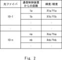
- 5 is a diagram showing an example of a correspondence table held by a detection unit according to the first embodiment
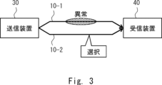
- FIG. 4A to 4C are diagrams illustrating specific examples of communication paths selected by a selection unit according to the first embodiment
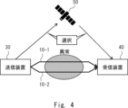
- 13 is a diagram showing another specific example of a communication path selected by the selection unit according to the first embodiment
- FIG. 1 is a flow diagram showing an example of a schematic operation flow of a communication control system according to a first embodiment.
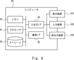
- 2 is a block diagram showing an example of a hardware configuration of a computer that realizes the communication control device according to the first embodiment;
- the communication control system according to the first embodiment includes a plurality of optical fibers 10-1 to 10-n (n is an integer of 2 or more) and a communication control device 20.
- n is an integer of 2 or more
- the optical fiber 10 when it is not necessary to specify which of the optical fibers 10-1 to 10-n is being referred to, it will be simply referred to as the "optical fiber 10.”
- the optical fiber 10 is laid in a specified area. There are no particular limitations on the manner in which the optical fiber 10 is laid.
- the optical fiber 10 may be laid overhead on a pole such as a utility pole, or may be buried underground.
- the communication control device 20 is a device for selecting a communication path to be used for a specific communication, and is realized by, for example, a sensing device such as a Distributed Fiber Optic Sensing (DFOS) device.
- the specific communication is, for example, communication that transmits data from a transmitting device to a receiving device.
- DFOS Distributed Fiber Optic Sensing
- the communication path that can be selected for use in a given communication is any one of the multiple optical fibers 10, and a wireless line via a communication satellite, base station, etc.
- the communication control device 20 includes a detection unit 21, a prediction unit 22, and a selection unit 23.
- a plurality of optical fibers 10 are connected to the detection unit 21 .
- the detection unit 21 transmits pulsed light to each of the plurality of optical fibers 10.
- the detection unit 21 receives backscattered light generated as the pulsed light is transmitted through each of the plurality of optical fibers 10 as an optical signal from each of the plurality of optical fibers 10.
- the vibrations caused by the abnormality are transmitted to the optical fiber 10, and the characteristics (e.g., wavelength) of the optical signal transmitted through the optical fiber 10 change.
- the detection unit 21 can detect vibrations transmitted to the optical fiber 10 based on the optical signal received from the optical fiber 10, and can also detect abnormalities that are the cause of the vibrations.
- the detection unit 21 can identify the location where the optical signal was generated, i.e., the location where the abnormality detected based on the optical signal occurred (the distance of the optical fiber 10 from the communication control device 20).
- the detection unit 21 also holds in advance a correspondence table that indicates, for each of the multiple optical fibers 10, the distance from the communication control device 20 on that optical fiber 10 and the latitude/longitude at that distance.
- An example of the correspondence table is shown in FIG. 2. Therefore, by using a correspondence table such as that shown in FIG. 2, the detection unit 21 can identify the latitude/longitude of the location where an abnormality has occurred. For example, in the example of FIG. 2, if an abnormality has occurred at a position on the optical fiber 10-1 that is a distance 1a from the communication control device 20, the detection unit 21 identifies the location where the abnormality has occurred as being at latitude/longitude X1a/Y1a.
- the correspondence table is not limited to being held by the detection unit 21.
- any component inside or outside the communication control device 20 may hold the correspondence table, and the detection unit 21 may read and use the correspondence table.
- the vibrations transmitted to the optical fiber 10 have unique vibration patterns that vary in strength, vibration position, and frequency fluctuation depending on the type of abnormality.
- the detection unit 21 may therefore estimate the type of abnormality in the external environment around the optical fiber 10 based on the vibration pattern of the vibration detected based on the optical signal.
- the types of abnormality in the external environment include, for example, landslides, earthquakes, traffic accidents, floods, tsunamis, and fires.
- the detection unit 21 may also use pattern matching or a learning model when estimating the type of abnormality in the external environment around the optical fiber 10.
- the learning model may also be a model that includes a CNN (Convolutional Neural Network).
- the detection unit 21 stores in advance, for each type of abnormality in the external environment, the vibration pattern that occurs when that type of abnormality occurs as a matching pattern. The detection unit 21 then compares the vibration pattern of the vibration detected based on the optical signal with the matching pattern. If there is a matching pattern among the matching patterns whose compatibility with the vibration pattern is equal to or exceeds a threshold value, the detection unit 21 determines that the type of abnormality in the external environment corresponds to that matching pattern.
- the detection unit 21 uses a learning model
- the detection unit 21 inputs multiple pairs of teacher data indicating the type of abnormality in the external environment and the vibration pattern when that type of abnormality occurs, and constructs and stores the learning model in advance.
- the detection unit 21 then inputs the vibration pattern of the vibration detected based on the optical signal to the learning model.
- the detection unit 21 obtains the type of abnormality in the external environment as the output result of the learning model.
- the matching patterns and learning models are not limited to being stored by the detection unit 21.
- any component inside or outside the communication control device 20 may store the matching patterns and learning models, and the detection unit 21 may read and use the matching patterns and learning models.
- the detection unit 21 may further estimate the scale of the abnormality in the external environment based on the estimated type of abnormality in the external environment.
- the prediction unit 22 predicts whether or not the communication path will be affected by the abnormality in the external environment, based on the abnormality in the external environment detected by the detection unit 21. For example, the prediction unit 22 may predict that a communication path that includes a location where a communication interruption may occur due to the abnormality in the external environment will be affected by the abnormality in the external environment.
- the prediction unit 22 may identify an area in which communication interruption may occur based on the estimated type and scale of the abnormality in the external environment, and when all or part of the communication path is included in the identified area, predict that the communication path will be affected by the abnormality in the external environment.
- the selection unit 23 selects a communication path that is not affected by an abnormality in the external environment as the communication path to be used for a specified communication, based on whether or not the communication path predicted by the prediction unit 22 is affected by an abnormality in the external environment.
- a specific example of a communication path selected by the selection unit 23 will be described.
- a communication path to be used for communication to transmit data from the transmitting device 30 to the receiving device 40 is selected. It is also assumed that two optical fibers 10-1 and 10-2 are laid between the transmitting device 30 and the receiving device 40.
- the prediction unit 22 predicts that only the optical fiber 10-1 will be affected by the abnormality in the external environment because the scale of the abnormality in the external environment is small. Therefore, the selector 23 selects the optical fiber 10-2, which is not affected by abnormalities in the external environment, as the communication path to be used for communication.
- the prediction unit 22 predicts that both of the two optical fibers 10-1 and 10-2 will be affected by the abnormality in the external environment because the abnormality in the external environment is large in scale. Therefore, the selection unit 23 selects, as the communication path to be used for communication, a wireless link via the communication satellite 50, which is not affected by abnormalities in the external environment.
- the selection unit 23 is not limited to selecting a wireless link via the communication satellite 50, and may select a wireless link via a base station (not shown) that is not affected by abnormalities in the external environment.
- the detection unit 21 transmits pulsed light to each of the multiple optical fibers 10 and receives optical signals from each of the multiple optical fibers 10. Then, the detection unit 21 detects an abnormality in the external environment around the multiple optical fibers 10 based on the optical signals received from each of the multiple optical fibers 10 (step S11).
- the prediction unit 22 predicts whether or not the abnormality in the external environment will have an effect on the communication path, based on the abnormality in the external environment detected by the detection unit 21 (step S12). Then, the selection unit 23 selects a communication path that is not affected by the abnormality in the external environment as the communication path to be used for the specified communication, based on whether or not the communication path predicted by the prediction unit 22 is affected by the abnormality in the external environment (step S13).
- the detection unit 21 detects an abnormality in the external environment surrounding the multiple optical fibers 10 based on the optical signals received from each of the multiple optical fibers 10.
- the prediction unit 22 predicts whether or not the communication path will be affected by the abnormality in the external environment based on the abnormality in the external environment detected by the detection unit 21.
- the selection unit 23 selects a communication path that is not affected by the abnormality in the external environment as the communication path to be used for the specified communication based on the presence or absence of the influence of the abnormality in the external environment on the communication path predicted by the prediction unit 22.
- the communication path to be used for the specified communication can be selected taking into consideration abnormalities in the external environment around the optical fiber 10. This allows the communication path to be selected while avoiding locations or areas where communication interruptions may occur due to abnormalities in the external environment. As a result, the specified communication can be continued without communication interruptions due to abnormalities in the external environment, and the specified communication can be realized stably.
- the optical fiber 10 which is also used as a communication path, is used. Therefore, there is no need to prepare a dedicated sensor for detecting abnormalities in the external environment, which can reduce costs.
- ⁇ Other embodiments> In the above-described first embodiment, only one detector 21 is provided, but the present invention is not limited to this.
- a plurality of detectors 21 may be provided corresponding to a plurality of optical fibers 10, respectively.
- the detector 21 may be connected only to the corresponding optical fiber 10, transmit pulsed light to the corresponding optical fiber 10, and receive an optical signal from the corresponding optical fiber 10.
- the detector 21 may detect only an abnormality in the external environment around the corresponding optical fiber 10, based on the optical signal received from the corresponding optical fiber 10.
- the selection unit 23 selects a communication path based on whether or not an abnormality in the external environment affects the communication path predicted by the prediction unit 22, but this is not limited to this.
- the selection unit 23 may determine the communication capacity during a given communication when the detection unit 21 detects an abnormality in the external environment. The selection unit 23 may then select a communication path based on the presence or absence of an effect of the abnormality in the external environment on the communication path predicted by the prediction unit 22 and the communication capacity determined above. For example, if the communication capacity exceeds the communication capacity of a single optical fiber 10, the selection unit 23 may select multiple optical fibers 10 that are not affected by the abnormality in the external environment as the communication path, or may select a wireless line.
- the selection unit 23 may determine the communication capacity of future communication in a given communication. The selection unit 23 may then select a communication path based on the presence or absence of an influence of an abnormality in the external environment on the communication path predicted by the prediction unit 22 and the communication capacity determined above.
- the selection unit 23 may determine the priority of a predetermined communication when the detection unit 21 detects an abnormality in the external environment. The selection unit 23 may then select a communication path based on the presence or absence of an influence of an abnormality in the external environment on the communication path predicted by the prediction unit 22 and the priority determined above. For example, a high priority may be set for a communication that requires real-time transmission, and a low priority may be set for a communication that does not require real-time transmission. Furthermore, when the priority of a predetermined communication is high, the selection unit 23 may select an optical fiber 10 that is not affected by an abnormality in the external environment as the communication path, in order to select an optical fiber 10 with a high communication speed. Furthermore, when the priority of a predetermined communication is low, the selection unit 23 may select a wireless line via a communication satellite with a low communication speed as the communication path.
- the computer 90 includes a processor 91, a memory 92, a storage 93, an input/output interface (input/output I/F) 94, and a communication interface (communication I/F) 95.
- the processor 91, the memory 92, the storage 93, the input/output interface 94, and the communication interface 95 are connected by a data transmission path for transmitting and receiving data to and from each other.
- the processor 91 is, for example, an arithmetic processing device such as a CPU (Central Processing Unit) or a GPU (Graphics Processing Unit).
- the memory 92 is, for example, a memory such as a RAM (Random Access Memory) or a ROM (Read Only Memory).
- the storage 93 is, for example, a storage device such as a HDD (Hard Disk Drive), an SSD (Solid State Drive), or a memory card.
- the storage 93 may also be a memory such as a RAM or ROM.
- Storage 93 stores programs that realize the functions of the components of communication control device 20.
- Processor 91 realizes the functions of the components of communication control device 20 by executing each of these programs.
- processor 91 executes each of the above programs, it may read these programs onto memory 92 and then execute them, or it may execute them without reading them onto memory 92.
- Memory 92 and storage 93 also serve to store information and data held by the components of communication control device 20.
- Non-transitory computer readable medium includes various types of tangible storage medium.
- Examples of non-transitory computer readable medium include magnetic recording media (e.g., flexible disks, magnetic tapes, hard disk drives), magneto-optical recording media (e.g., magneto-optical disks), Compact Disc-ROM (CD-ROM), CD-Recordable (CD-R), CD-ReWritable (CD-R/W), and semiconductor memory (e.g., mask ROM, Programmable ROM (PROM), Erasable PROM (EPROM), flash ROM, RAM).
- magnetic recording media e.g., flexible disks, magnetic tapes, hard disk drives
- magneto-optical recording media e.g., magneto-optical disks
- CD-ROM Compact Disc-ROM
- CD-R CD-Recordable
- CD-R/W CD-ReWritable
- semiconductor memory e.g., mask ROM, Programmable ROM (PROM), Erasable PROM (EPROM), flash ROM,
- the program may also be supplied to a computer by various types of transitory computer readable medium.
- Examples of transitory computer readable medium include electrical signals, optical signals, and electromagnetic waves.
- the temporary computer-readable medium can provide the program to the computer via a wired communication path, such as an electric wire or optical fiber, or via a wireless communication path.
- the input/output interface 94 is connected to a display device 941, an input device 942, a sound output device 943, etc.
- the display device 941 is a device that displays a screen corresponding to drawing data processed by the processor 91, such as an LCD (Liquid Crystal Display), a CRT (Cathode Ray Tube) display, or a monitor.
- the input device 942 is a device that accepts operational input from an operator, such as a keyboard, a mouse, or a touch sensor.
- the display device 941 and the input device 942 may be integrated and realized as a touch panel.
- the sound output device 943 is a device that acoustically outputs sound corresponding to the audio data processed by the processor 91, such as a speaker.
- the communication interface 95 transmits and receives data to and from an external device.
- the communication interface 95 communicates with the external device via a wired communication path or a wireless communication path.
- Appendix 1 A plurality of optical fibers; a detection unit that detects an abnormality in an external environment around the plurality of optical fibers based on an optical signal received from each of the plurality of optical fibers; a prediction unit that predicts whether or not the abnormality has an effect on a communication path based on the detected abnormality; a selection unit that selects a communication path that is not affected by the abnormality as a communication path to be used for a predetermined communication based on the presence or absence of an influence of the abnormality on the predicted communication path, Communications control system.
- the detection unit is Estimating a type and a magnitude of the detected anomaly based on the optical signal;
- the prediction unit is predicting whether or not the abnormality has an effect on a communication path based on the estimated type and scale of the abnormality; 2.
- the communication control system of claim 1. (Appendix 3)
- the selection unit is determining a communication capacity during the predetermined communication when the abnormality is detected; selecting a communication path to be used for the predetermined communication based on the presence or absence of the influence of the abnormality on the predicted communication path and the determined communication capacity; 2.
- the selection unit is determining a communication capacity for future communication in the predetermined communication; selecting a communication path to be used for the predetermined communication based on the presence or absence of the influence of the abnormality on the predicted communication path and the determined communication capacity; 2.
- the communication control system of claim 1. (Appendix 5) The selection unit is determining a priority of the predetermined communication when the abnormality is detected; selecting a communication path to be used for the predetermined communication based on the presence or absence of an influence of the abnormality on the predicted communication path and the determined priority; 2.
- the communication control system of claim 1. (Appendix 6) The selection unit is selecting one of the plurality of optical fibers or selecting a wireless line as a communication path to be used for the predetermined communication; 6.
- a communication control system according to any one of claims 1 to 5.
- (Appendix 7) a detection unit that detects an abnormality in an external environment around the plurality of optical fibers based on an optical signal received from each of the plurality of optical fibers; a prediction unit that predicts whether or not the abnormality has an effect on a communication path based on the detected abnormality; a selection unit that selects a communication path that is not affected by the abnormality as a communication path to be used for a predetermined communication based on the presence or absence of an influence of the abnormality on the predicted communication path, Communications control device.
- the detection unit is Estimating a type and a magnitude of the detected anomaly based on the optical signal;
- the prediction unit is predicting whether or not the abnormality has an effect on a communication path based on the estimated type and scale of the abnormality;
- the communication control device of claim 7. (Appendix 9)
- the selection unit is determining a communication capacity during the predetermined communication when the abnormality is detected; selecting a communication path to be used for the predetermined communication based on the presence or absence of the influence of the abnormality on the predicted communication path and the determined communication capacity; 8.
- the selection unit is Determining a communication capacity for future communication in the predetermined communication; selecting a communication path to be used for the predetermined communication based on the presence or absence of the influence of the abnormality on the predicted communication path and the determined communication capacity; 8. The communication control device of claim 7. (Appendix 11) The selection unit is determining a priority of the predetermined communication when the abnormality is detected; selecting a communication path to be used for the predetermined communication based on the presence or absence of an influence of the abnormality on the predicted communication path and the determined priority; 8. The communication control device of claim 7. (Appendix 12) The selection unit is selecting one of the plurality of optical fibers or selecting a wireless line as a communication path to be used for the predetermined communication; 12.
- a communication control method by a communication control device a detection step of detecting an abnormality in an external environment around the plurality of optical fibers based on an optical signal received from each of the plurality of optical fibers; a prediction step of predicting whether or not the abnormality has an effect on a communication path based on the detected abnormality; and selecting a communication path that is not affected by the abnormality as a communication path to be used for a predetermined communication based on the presence or absence of an influence of the abnormality on the predicted communication path.
- Communications control method is a communication control device, a detection step of detecting an abnormality in an external environment around the plurality of optical fibers based on an optical signal received from each of the plurality of optical fibers; a prediction step of predicting whether or not the abnormality has an effect on a communication path based on the detected abnormality; and selecting a communication path that is not affected by the abnormality as a communication path to be used for a predetermined communication based on the presence or absence of an influence of the abnormality on the predicted communication
- (Appendix 16) In the selection step, Determining a communication capacity for future communication in the predetermined communication; selecting a communication path to be used for the predetermined communication based on the presence or absence of the influence of the abnormality on the predicted communication path and the determined communication capacity; 14. A communication control method as described in claim 13. (Appendix 17) In the selection step, determining a priority of the predetermined communication when the abnormality is detected; selecting a communication path to be used for the predetermined communication based on the presence or absence of an influence of the abnormality on the predicted communication path and the determined priority; 14. A communication control method as described in claim 13. (Appendix 18) In the selection step, selecting one of the plurality of optical fibers or selecting a wireless line as a communication path to be used for the predetermined communication; 18. A communication control method according to any one of appendix 13 to 17.
Landscapes
- Engineering & Computer Science (AREA)
- Computer Networks & Wireless Communication (AREA)
- Signal Processing (AREA)
- Optical Communication System (AREA)
Abstract
Description
具体的には、特許文献1に記載の技術によれば、各中継器における伝送品質などに基づいて、各中継器における異常を予測し、複数の通信経路の中から、異常が予測された中継器を含む通信経路を除外した上で、通信経路を選択する。
複数本の光ファイバと、
前記複数本の光ファイバの各々から受信した光信号に基づいて、前記複数本の光ファイバの周囲の外部環境の異常を検知する検知部と、
前記検知された前記異常に基づいて、通信経路への前記異常の影響の有無を予測する予測部と、
前記予測された通信経路への前記異常の影響の有無に基づいて、所定の通信に用いる通信経路として、前記異常の影響を受けない通信経路を選択する選択部と、を備える。
複数本の光ファイバの各々から受信した光信号に基づいて、前記複数本の光ファイバの周囲の外部環境の異常を検知する検知部と、
前記検知された前記異常に基づいて、通信経路への前記異常の影響の有無を予測する予測部と、
前記予測された通信経路への前記異常の影響の有無に基づいて、所定の通信に用いる通信経路として、前記異常の影響を受けない通信経路を選択する選択部と、を備える。
通信制御装置による通信制御方法であって、
複数本の光ファイバの各々から受信した光信号に基づいて、前記複数本の光ファイバの周囲の外部環境の異常を検知する検知ステップと、
前記検知された前記異常に基づいて、通信経路への前記異常の影響の有無を予測する予測ステップと、
前記予測された通信経路への前記異常の影響の有無に基づいて、所定の通信に用いる通信経路として、前記異常の影響を受けない通信経路を選択する選択ステップと、を含む。
まず、図1を参照して、本実施の形態1に係る通信制御システムの構成例について説明する。
図1に示されるように、本実施の形態1に係る通信制御システムは、複数本の光ファイバ10-1~10-n(nは2以上の整数)及び通信制御装置20を備えている。以下、どの光ファイバ10-1~10-nであるかを特定しない場合は、単に「光ファイバ10」と適宜称する。
検知部21には、複数本の光ファイバ10が接続される。
検知部21は、複数本の光ファイバ10の各々にパルス光を送信する。また、検知部21は、複数本の光ファイバ10の各々をパルス光が伝送されることに伴い発生した後方散乱光を、複数本の光ファイバ10の各々から、光信号として受信する。
そのため、選択部23は、通信に用いる通信経路として、外部環境の異常の影響を受けない光ファイバ10-2を選択する。
そのため、選択部23は、通信に用いる通信経路として、外部環境の異常の影響を受けない、通信衛星50経由の無線回線を選択する。ただし、図4の例では、通信衛星50経由の無線回線を選択することには限定されず、選択部23は、外部環境の異常の影響を受けない基地局(不図示)経由の無線回線を選択しても良い。
図5に示されるように、検知部21は、複数本の光ファイバ10の各々にパルス光を送信すると共に、複数本の光ファイバ10の各々から光信号を受信する。そして、検知部21は、複数本の光ファイバ10の各々から受信した光信号に基づいて、複数本の光ファイバ10の周囲の外部環境の異常を検知する(ステップS11)。
その後、選択部23は、予測部22により予測された通信経路への外部環境の異常の影響の有無に基づいて、所定の通信に用いる通信経路として、外部環境の異常の影響を受けない通信経路を選択する(ステップS13)。
上述した実施の形態1では、検知部21を1つのみ設けているが、これには限定されない。例えば、複数本の光ファイバ10にそれぞれ対応して、複数の検知部21を設けても良い。この場合、検知部21は、対応する光ファイバ10にのみ接続され、対応する光ファイバ10にパルス光を送信し、対応する光ファイバ10から光信号を受信しても良い。また、検知部21は、対応する光ファイバ10から受信された光信号に基づいて、対応する光ファイバ10の周囲の外部環境の異常のみを検知しても良い。
続いて、図6を参照して、上述した実施の形態1に係る通信制御装置20を実現するコンピュータ90のハードウェア構成例について説明する。
(付記1)
複数本の光ファイバと、
前記複数本の光ファイバの各々から受信した光信号に基づいて、前記複数本の光ファイバの周囲の外部環境の異常を検知する検知部と、
前記検知された前記異常に基づいて、通信経路への前記異常の影響の有無を予測する予測部と、
前記予測された通信経路への前記異常の影響の有無に基づいて、所定の通信に用いる通信経路として、前記異常の影響を受けない通信経路を選択する選択部と、を備える、
通信制御システム。
(付記2)
前記検知部は、
前記光信号に基づいて、前記検知された前記異常の種類及び規模を推定し、
前記予測部は、
前記推定された前記異常の種類及び規模に基づいて、通信経路への前記異常の影響の有無を予測する、
付記1に記載の通信制御システム。
(付記3)
前記選択部は、
前記異常が検知されたときに前記所定の通信にて通信中の通信容量を判別し、
前記予測された通信経路への前記異常の影響の有無及び前記判別された前記通信容量に基づいて、前記所定の通信に用いる通信経路を選択する、
付記1に記載の通信制御システム。
(付記4)
前記選択部は、
前記所定の通信にて今後に通信予定の通信容量を判別し、
前記予測された通信経路への前記異常の影響の有無及び前記判別された前記通信容量に基づいて、前記所定の通信に用いる通信経路を選択する、
付記1に記載の通信制御システム。
(付記5)
前記選択部は、
前記異常が検知されたときの前記所定の通信の優先度を判別し、
前記予測された通信経路への前記異常の影響の有無及び前記判別された前記優先度に基づいて、前記所定の通信に用いる通信経路を選択する、
付記1に記載の通信制御システム。
(付記6)
前記選択部は、
前記所定の通信に用いる通信経路として、前記複数本の光ファイバのいずれかを選択するか、又は、無線回線を選択する、
付記1から5のいずれか1項に記載の通信制御システム。
(付記7)
複数本の光ファイバの各々から受信した光信号に基づいて、前記複数本の光ファイバの周囲の外部環境の異常を検知する検知部と、
前記検知された前記異常に基づいて、通信経路への前記異常の影響の有無を予測する予測部と、
前記予測された通信経路への前記異常の影響の有無に基づいて、所定の通信に用いる通信経路として、前記異常の影響を受けない通信経路を選択する選択部と、を備える、
通信制御装置。
(付記8)
前記検知部は、
前記光信号に基づいて、前記検知された前記異常の種類及び規模を推定し、
前記予測部は、
前記推定された前記異常の種類及び規模に基づいて、通信経路への前記異常の影響の有無を予測する、
付記7に記載の通信制御装置。
(付記9)
前記選択部は、
前記異常が検知されたときに前記所定の通信にて通信中の通信容量を判別し、
前記予測された通信経路への前記異常の影響の有無及び前記判別された前記通信容量に基づいて、前記所定の通信に用いる通信経路を選択する、
付記7に記載の通信制御装置。
(付記10)
前記選択部は、
前記所定の通信にて今後に通信予定の通信容量を判別し、
前記予測された通信経路への前記異常の影響の有無及び前記判別された前記通信容量に基づいて、前記所定の通信に用いる通信経路を選択する、
付記7に記載の通信制御装置。
(付記11)
前記選択部は、
前記異常が検知されたときの前記所定の通信の優先度を判別し、
前記予測された通信経路への前記異常の影響の有無及び前記判別された前記優先度に基づいて、前記所定の通信に用いる通信経路を選択する、
付記7に記載の通信制御装置。
(付記12)
前記選択部は、
前記所定の通信に用いる通信経路として、前記複数本の光ファイバのいずれかを選択するか、又は、無線回線を選択する、
付記7から11のいずれか1項に記載の通信制御装置。
(付記13)
通信制御装置による通信制御方法であって、
複数本の光ファイバの各々から受信した光信号に基づいて、前記複数本の光ファイバの周囲の外部環境の異常を検知する検知ステップと、
前記検知された前記異常に基づいて、通信経路への前記異常の影響の有無を予測する予測ステップと、
前記予測された通信経路への前記異常の影響の有無に基づいて、所定の通信に用いる通信経路として、前記異常の影響を受けない通信経路を選択する選択ステップと、を含む、
通信制御方法。
(付記14)
前記検知ステップでは、
前記光信号に基づいて、前記検知された前記異常の種類及び規模を推定し、
前記予測ステップでは、
前記推定された前記異常の種類及び規模に基づいて、通信経路への前記異常の影響の有無を予測する、
付記13に記載の通信制御方法。
(付記15)
前記選択ステップでは、
前記異常が検知されたときに前記所定の通信にて通信中の通信容量を判別し、
前記予測された通信経路への前記異常の影響の有無及び前記判別された前記通信容量に基づいて、前記所定の通信に用いる通信経路を選択する、
付記13に記載の通信制御方法。
(付記16)
前記選択ステップでは、
前記所定の通信にて今後に通信予定の通信容量を判別し、
前記予測された通信経路への前記異常の影響の有無及び前記判別された前記通信容量に基づいて、前記所定の通信に用いる通信経路を選択する、
付記13に記載の通信制御方法。
(付記17)
前記選択ステップでは、
前記異常が検知されたときの前記所定の通信の優先度を判別し、
前記予測された通信経路への前記異常の影響の有無及び前記判別された前記優先度に基づいて、前記所定の通信に用いる通信経路を選択する、
付記13に記載の通信制御方法。
(付記18)
前記選択ステップでは、
前記所定の通信に用いる通信経路として、前記複数本の光ファイバのいずれかを選択するか、又は、無線回線を選択する、
付記13から17のいずれか1項に記載の通信制御方法。
20 通信制御装置
21 検知部
22 予測部
23 選択部
30 送信装置
40 受信装置
50 通信衛星
90 コンピュータ
91 プロセッサ
92 メモリ
93 ストレージ
94 入出力インタフェース
941 表示装置
942 入力装置
943 音出力装置
95 通信インタフェース
Claims (18)
- 複数本の光ファイバと、
前記複数本の光ファイバの各々から受信した光信号に基づいて、前記複数本の光ファイバの周囲の外部環境の異常を検知する検知部と、
前記検知された前記異常に基づいて、通信経路への前記異常の影響の有無を予測する予測部と、
前記予測された通信経路への前記異常の影響の有無に基づいて、所定の通信に用いる通信経路として、前記異常の影響を受けない通信経路を選択する選択部と、を備える、
通信制御システム。 - 前記検知部は、
前記光信号に基づいて、前記検知された前記異常の種類及び規模を推定し、
前記予測部は、
前記推定された前記異常の種類及び規模に基づいて、通信経路への前記異常の影響の有無を予測する、
請求項1に記載の通信制御システム。 - 前記選択部は、
前記異常が検知されたときに前記所定の通信にて通信中の通信容量を判別し、
前記予測された通信経路への前記異常の影響の有無及び前記判別された前記通信容量に基づいて、前記所定の通信に用いる通信経路を選択する、
請求項1に記載の通信制御システム。 - 前記選択部は、
前記所定の通信にて今後に通信予定の通信容量を判別し、
前記予測された通信経路への前記異常の影響の有無及び前記判別された前記通信容量に基づいて、前記所定の通信に用いる通信経路を選択する、
請求項1に記載の通信制御システム。 - 前記選択部は、
前記異常が検知されたときの前記所定の通信の優先度を判別し、
前記予測された通信経路への前記異常の影響の有無及び前記判別された前記優先度に基づいて、前記所定の通信に用いる通信経路を選択する、
請求項1に記載の通信制御システム。 - 前記選択部は、
前記所定の通信に用いる通信経路として、前記複数本の光ファイバのいずれかを選択するか、又は、無線回線を選択する、
請求項1から5のいずれか1項に記載の通信制御システム。 - 複数本の光ファイバの各々から受信した光信号に基づいて、前記複数本の光ファイバの周囲の外部環境の異常を検知する検知部と、
前記検知された前記異常に基づいて、通信経路への前記異常の影響の有無を予測する予測部と、
前記予測された通信経路への前記異常の影響の有無に基づいて、所定の通信に用いる通信経路として、前記異常の影響を受けない通信経路を選択する選択部と、を備える、
通信制御装置。 - 前記検知部は、
前記光信号に基づいて、前記検知された前記異常の種類及び規模を推定し、
前記予測部は、
前記推定された前記異常の種類及び規模に基づいて、通信経路への前記異常の影響の有無を予測する、
請求項7に記載の通信制御装置。 - 前記選択部は、
前記異常が検知されたときに前記所定の通信にて通信中の通信容量を判別し、
前記予測された通信経路への前記異常の影響の有無及び前記判別された前記通信容量に基づいて、前記所定の通信に用いる通信経路を選択する、
請求項7に記載の通信制御装置。 - 前記選択部は、
前記所定の通信にて今後に通信予定の通信容量を判別し、
前記予測された通信経路への前記異常の影響の有無及び前記判別された前記通信容量に基づいて、前記所定の通信に用いる通信経路を選択する、
請求項7に記載の通信制御装置。 - 前記選択部は、
前記異常が検知されたときの前記所定の通信の優先度を判別し、
前記予測された通信経路への前記異常の影響の有無及び前記判別された前記優先度に基づいて、前記所定の通信に用いる通信経路を選択する、
請求項7に記載の通信制御装置。 - 前記選択部は、
前記所定の通信に用いる通信経路として、前記複数本の光ファイバのいずれかを選択するか、又は、無線回線を選択する、
請求項7から11のいずれか1項に記載の通信制御装置。 - 通信制御装置による通信制御方法であって、
複数本の光ファイバの各々から受信した光信号に基づいて、前記複数本の光ファイバの周囲の外部環境の異常を検知する検知ステップと、
前記検知された前記異常に基づいて、通信経路への前記異常の影響の有無を予測する予測ステップと、
前記予測された通信経路への前記異常の影響の有無に基づいて、所定の通信に用いる通信経路として、前記異常の影響を受けない通信経路を選択する選択ステップと、を含む、
通信制御方法。 - 前記検知ステップでは、
前記光信号に基づいて、前記検知された前記異常の種類及び規模を推定し、
前記予測ステップでは、
前記推定された前記異常の種類及び規模に基づいて、通信経路への前記異常の影響の有無を予測する、
請求項13に記載の通信制御方法。 - 前記選択ステップでは、
前記異常が検知されたときに前記所定の通信にて通信中の通信容量を判別し、
前記予測された通信経路への前記異常の影響の有無及び前記判別された前記通信容量に基づいて、前記所定の通信に用いる通信経路を選択する、
請求項13に記載の通信制御方法。 - 前記選択ステップでは、
前記所定の通信にて今後に通信予定の通信容量を判別し、
前記予測された通信経路への前記異常の影響の有無及び前記判別された前記通信容量に基づいて、前記所定の通信に用いる通信経路を選択する、
請求項13に記載の通信制御方法。 - 前記選択ステップでは、
前記異常が検知されたときの前記所定の通信の優先度を判別し、
前記予測された通信経路への前記異常の影響の有無及び前記判別された前記優先度に基づいて、前記所定の通信に用いる通信経路を選択する、
請求項13に記載の通信制御方法。 - 前記選択ステップでは、
前記所定の通信に用いる通信経路として、前記複数本の光ファイバのいずれかを選択するか、又は、無線回線を選択する、
請求項13から17のいずれか1項に記載の通信制御方法。
Priority Applications (2)
| Application Number | Priority Date | Filing Date | Title |
|---|---|---|---|
| JP2025509389A JPWO2024201773A1 (ja) | 2023-03-29 | 2023-03-29 | |
| PCT/JP2023/012790 WO2024201773A1 (ja) | 2023-03-29 | 2023-03-29 | 通信制御システム、通信制御装置、及び通信制御方法 |
Applications Claiming Priority (1)
| Application Number | Priority Date | Filing Date | Title |
|---|---|---|---|
| PCT/JP2023/012790 WO2024201773A1 (ja) | 2023-03-29 | 2023-03-29 | 通信制御システム、通信制御装置、及び通信制御方法 |
Publications (1)
| Publication Number | Publication Date |
|---|---|
| WO2024201773A1 true WO2024201773A1 (ja) | 2024-10-03 |
Family
ID=92903603
Family Applications (1)
| Application Number | Title | Priority Date | Filing Date |
|---|---|---|---|
| PCT/JP2023/012790 Ceased WO2024201773A1 (ja) | 2023-03-29 | 2023-03-29 | 通信制御システム、通信制御装置、及び通信制御方法 |
Country Status (2)
| Country | Link |
|---|---|
| JP (1) | JPWO2024201773A1 (ja) |
| WO (1) | WO2024201773A1 (ja) |
Citations (5)
| Publication number | Priority date | Publication date | Assignee | Title |
|---|---|---|---|---|
| JPH1155285A (ja) * | 1997-08-07 | 1999-02-26 | Nippon Telegr & Teleph Corp <Ntt> | Atm通信網 |
| JP2011193263A (ja) * | 2010-03-15 | 2011-09-29 | Nec Access Technica Ltd | 光信号冗長システム、光信号分配装置及び光信号冗長方法 |
| WO2011121705A1 (ja) * | 2010-03-29 | 2011-10-06 | 三菱電機株式会社 | 通信装置、通信システムおよび経路切替方法 |
| JP2015115751A (ja) * | 2013-12-11 | 2015-06-22 | Kddi株式会社 | 光回線障害検出装置、光/無線回線切替装置および光伝送システム |
| WO2020202654A1 (ja) * | 2019-03-29 | 2020-10-08 | 日本電気株式会社 | 監視システム、監視装置、監視方法、及び非一時的なコンピュータ可読媒体 |
-
2023
- 2023-03-29 WO PCT/JP2023/012790 patent/WO2024201773A1/ja not_active Ceased
- 2023-03-29 JP JP2025509389A patent/JPWO2024201773A1/ja active Pending
Patent Citations (5)
| Publication number | Priority date | Publication date | Assignee | Title |
|---|---|---|---|---|
| JPH1155285A (ja) * | 1997-08-07 | 1999-02-26 | Nippon Telegr & Teleph Corp <Ntt> | Atm通信網 |
| JP2011193263A (ja) * | 2010-03-15 | 2011-09-29 | Nec Access Technica Ltd | 光信号冗長システム、光信号分配装置及び光信号冗長方法 |
| WO2011121705A1 (ja) * | 2010-03-29 | 2011-10-06 | 三菱電機株式会社 | 通信装置、通信システムおよび経路切替方法 |
| JP2015115751A (ja) * | 2013-12-11 | 2015-06-22 | Kddi株式会社 | 光回線障害検出装置、光/無線回線切替装置および光伝送システム |
| WO2020202654A1 (ja) * | 2019-03-29 | 2020-10-08 | 日本電気株式会社 | 監視システム、監視装置、監視方法、及び非一時的なコンピュータ可読媒体 |
Also Published As
| Publication number | Publication date |
|---|---|
| JPWO2024201773A1 (ja) | 2024-10-03 |
Similar Documents
| Publication | Publication Date | Title |
|---|---|---|
| JP7124875B2 (ja) | 電柱位置特定システム、電柱位置特定装置、電柱位置特定方法、及びプログラム | |
| JP2023099542A (ja) | 電柱劣化検出システム、電柱劣化検出装置、電柱劣化検出方法、及びプログラム | |
| EP3913961B1 (en) | Radio operation management system and radio operation assistant method | |
| JP7552808B2 (ja) | 風速特定システム、風速特定装置、及び風速特定方法 | |
| CN114127519A (zh) | 光纤感测系统、光纤感测装置和用于检测管道劣化的方法 | |
| US20240377242A1 (en) | Optical fiber sensing system, optical fiber sensing apparatus, and breakage detection method | |
| US12009855B2 (en) | Monitoring system, monitoring device, and monitoring method | |
| US20220291262A1 (en) | Optical fiber sensing system, optical fiber sensing equipment, and power outage detection method | |
| WO2024201773A1 (ja) | 通信制御システム、通信制御装置、及び通信制御方法 | |
| WO2024184959A1 (ja) | 光ファイバセンシングシステム、光ファイバセンシング装置、及び光ファイバセンシング方法 | |
| JP7444289B2 (ja) | 位置特定システム、振動発生器、及び位置特定方法 | |
| US20240385032A1 (en) | Optical fiber sensing system, optical fiber sensing device, and road monitoring method | |
| JP7613483B2 (ja) | 通信ケーブル障害推定装置、方法およびプログラム | |
| US20250003792A1 (en) | Optical fiber sensing system, optical fiber sensing apparatus, and optical fiber sensing method | |
| US20240361178A1 (en) | Monitoring system, monitoring apparatus, and monitoring method | |
| US20240353253A1 (en) | Detection system, detection apparatus, and detection method | |
| US20250003791A1 (en) | Optical fiber sensing system, optical fiber sensing apparatus, and route determination method | |
| CN119324740A (zh) | 一种用于管道伴行光缆的故障点位确定方法和系统 | |
| US20230081172A1 (en) | Power failure detection system, power failure detection device, and power failure detection method | |
| WO2021240670A1 (ja) | 異常検出システム、異常検出装置、異常検出方法、及びコンピュータ可読媒体 | |
| JP7043916B2 (ja) | 測位システム、データ処理装置、データ処理方法、プログラム、通信器および音響受信器 | |
| JP7364046B2 (ja) | 異常検知システム、異常検知装置、及び異常検知方法 | |
| US20250198390A1 (en) | Deterioration detection system, deterioration detection apparatus, and deterioration detection method | |
| JP2025005067A (ja) | 光ファイバセンシングシステム、制御装置、及び制御方法 | |
| WO2024201664A1 (ja) | 監視システム、監視装置、及び監視方法 |
Legal Events
| Date | Code | Title | Description |
|---|---|---|---|
| 121 | Ep: the epo has been informed by wipo that ep was designated in this application |
Ref document number: 23930413 Country of ref document: EP Kind code of ref document: A1 |
|
| ENP | Entry into the national phase |
Ref document number: 2025509389 Country of ref document: JP Kind code of ref document: A |
|
| WWE | Wipo information: entry into national phase |
Ref document number: 2025509389 Country of ref document: JP |
|
| NENP | Non-entry into the national phase |
Ref country code: DE |
|
| 122 | Ep: pct application non-entry in european phase |
Ref document number: 23930413 Country of ref document: EP Kind code of ref document: A1 |