WO2024201769A1 - センターピラー - Google Patents
センターピラー Download PDFInfo
- Publication number
- WO2024201769A1 WO2024201769A1 PCT/JP2023/012779 JP2023012779W WO2024201769A1 WO 2024201769 A1 WO2024201769 A1 WO 2024201769A1 JP 2023012779 W JP2023012779 W JP 2023012779W WO 2024201769 A1 WO2024201769 A1 WO 2024201769A1
- Authority
- WO
- WIPO (PCT)
- Prior art keywords
- center pillar
- tubular member
- outer layer
- region
- fiber
- Prior art date
- Legal status (The legal status is an assumption and is not a legal conclusion. Google has not performed a legal analysis and makes no representation as to the accuracy of the status listed.)
- Ceased
Links
Images




Classifications
-
- B—PERFORMING OPERATIONS; TRANSPORTING
- B62—LAND VEHICLES FOR TRAVELLING OTHERWISE THAN ON RAILS
- B62D—MOTOR VEHICLES; TRAILERS
- B62D25/00—Superstructure or monocoque structure sub-units; Parts or details thereof not otherwise provided for
- B62D25/04—Door pillars ; windshield pillars
-
- B—PERFORMING OPERATIONS; TRANSPORTING
- B62—LAND VEHICLES FOR TRAVELLING OTHERWISE THAN ON RAILS
- B62D—MOTOR VEHICLES; TRAILERS
- B62D29/00—Superstructures, understructures, or sub-units thereof, characterised by the material thereof
- B62D29/04—Superstructures, understructures, or sub-units thereof, characterised by the material thereof predominantly of synthetic material
-
- B—PERFORMING OPERATIONS; TRANSPORTING
- B62—LAND VEHICLES FOR TRAVELLING OTHERWISE THAN ON RAILS
- B62D—MOTOR VEHICLES; TRAILERS
- B62D29/00—Superstructures, understructures, or sub-units thereof, characterised by the material thereof
- B62D29/04—Superstructures, understructures, or sub-units thereof, characterised by the material thereof predominantly of synthetic material
- B62D29/043—Superstructures
Definitions
- the technology disclosed herein relates to a center pillar made of a fiber-reinforced plastic composite material.
- CFRP carbon fiber reinforced resin
- Structural materials made of fiber-reinforced resins have high rigidity, and in particular demonstrate high strength against compressive or tensile stress acting in the direction of the fiber orientation.
- Patent Documents 1 and 2 disclose center pillars that use CFRP materials as part of their components.
- the center pillar in order to reduce the weight of the vehicle body, it is desirable for many of the components of the center pillar to be made from CFRP materials.
- CFRP materials even when the center pillar is mainly made of CFRP materials, it is required to have the same functionality as a conventional steel center pillar. Specifically, in the event of a side collision of the vehicle, the upper part of the center pillar needs to be prevented from breaking in order to protect the heads of the occupants, and the lower part of the center pillar needs to absorb the collision energy.
- the technology disclosed herein has been developed in consideration of the above problems, and the purpose of this disclosure is to provide a center pillar made of fiber-reinforced resin that is capable of absorbing collision energy at the bottom of the center pillar in the event of a side collision while maintaining the structural continuity of the center pillar.
- a center pillar made of a fiber-reinforced resin composite material A plurality of tubular members made of fiber reinforced resin are continuous from an upper portion to a lower portion of the center along a longitudinal direction of the center pillar; and an outer layer portion made of a fiber-reinforced resin including reinforcing fibers arranged around the plurality of tubular members and wound around the tubular members,
- the plurality of fiber-reinforced resin tubular members include a first tubular member and a second tubular member aligned in a front-rear direction of the vehicle body, In a first region of the upper portion of the center pillar, the first tubular member and the second tubular member are in contact with the outer layer portion located on the outer side in the vehicle width direction, while in a second region of the lower portion of the center pillar, the first tubular member and the second tubular member are spaced apart from the outer layer portion located on the outer side in the vehicle width direction.
- a center pillar made of a fiber-reinforced resin composite material, A
- the technology disclosed herein can provide a center pillar made of fiber-reinforced resin that can absorb impact energy at the bottom of the center pillar during a side impact while maintaining the structural continuity of the center pillar.
- FIG. 1 is a schematic diagram showing an overall configuration of a vehicle body side structure according to an embodiment of the present invention
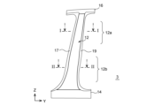
- FIG. 2 is an explanatory diagram for explaining the configuration of a center pillar according to the embodiment.
- 4 is an explanatory diagram showing a cross-sectional configuration of a first region of an upper portion of the center pillar according to the embodiment;
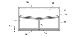
- FIG. 4 is an explanatory diagram showing a cross-sectional configuration of a second region of a lower portion of the center pillar according to the embodiment;
- FIG. 13 is an explanatory diagram showing an example in which a third cylindrical member is disposed in the cavity of the second region.
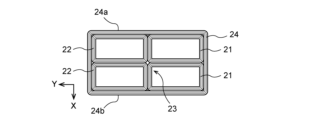
- FIG. 10 is an explanatory diagram showing a cross-sectional configuration of a first region of an upper portion of a center pillar according to a modified example of the embodiment.
- FIG. 10 is an explanatory diagram showing a cross-sectional configuration of a second region of a lower part of a center pillar according to a modified example of the embodiment.
- FIG. 10 is an explanatory diagram showing a cross-sectional configuration of a first region of an upper portion of a center pillar according to a modified example of the embodiment.
- FIG. 10 is an explanatory diagram showing a cross-sectional configuration of a second region of a lower part of a center pillar according to a modified example of the embodiment.
- Fig. 1 is a schematic diagram showing the appearance of a vehicle body side structure 1.
- the vehicle body side structure 1 shown in Fig. 1 shows a schematic view of a part of the structure of the left side of a vehicle.
- the vehicle width direction may be expressed as the X direction, the front-rear direction of the vehicle body as the Y direction, and the height direction of the vehicle body as the Z direction.
- the vehicle body side structure 1 is composed of a roof pillar 5, a rear pillar 4, a front pillar 2, a center pillar 3, and a side sill 6.
- the roof pillar 5 extends in the fore-and-aft direction of the vehicle body in the upper part of the vehicle interior space, and forms the side part of the vehicle roof.
- the side sill 6 extends in the fore-and-aft direction of the vehicle body in the lower part of the side of the vehicle.
- the front pillar 2 has its lower end connected to the front end of the side sill 6 and its upper end connected to the front end of the roof pillar 5.
- the front pillar 2 forms the front part that constitutes the interior space of the vehicle, and is positioned to support the side of the windshield.
- the rear pillar 4 has its lower end connected to the rear end of the side sill 6 and its upper end connected to the rear end of the roof pillar 5.
- the center pillar 3 has its lower end connected to the center of the side sill 6 in the fore-aft direction of the vehicle body, and its upper end connected to the center of the roof pillar 5 in the fore-aft direction of the vehicle body.
- Each member constituting the vehicle body side structure 1 may be composed of a plurality of members.
- each member may be composed of an outer panel on the outside in the vehicle width direction and an inner panel on the inside in the vehicle width direction joined together.
- the center pillar 3 has a longitudinal direction along the height direction and is formed in a columnar shape.
- the center pillar 3 has a roof pillar connection part 16 provided at the upper end, a side sill connection part 14 provided at the lower end, and a pillar main body part 12 located between the roof pillar connection part 16 and the side sill connection part 14.
- the center pillar 3 is made of a carbon fiber reinforced resin composite material.
- Figures 2 to 4 are diagrams for explaining the configuration of the center pillar 3.
- the center pillar 3 shown in Figures 2 to 4 is a simplified version of the center pillar 3 of the vehicle body side structure 1 shown in Figure 1.
- Figure 2 shows the center pillar 3 as viewed from the outside in the vehicle width direction.
- Figure 3 shows a cross-sectional view taken along line II of the first region 12a of the pillar main body portion 12 shown in Figure 2.
- Figure 4 shows a cross-sectional view taken along line II-II of the second region 12b of the pillar main body portion 12 shown in Figure 2.
- the center pillar 3 has a roof pillar connection portion 16, a side sill connection portion 14, a pillar body portion 12, and flanges 17, 19.
- Each of these components is made of CFRP material, but some may include metal components for connection or reinforcement (not shown).
- the roof pillar connection portion 16 and the side sill connection portion 14 are connected to the upper and lower ends of the pillar main body portion 12, respectively, and form grooves extending in the fore-and-aft direction of the vehicle body that fit into the roof pillar 5 and the side sill 6.
- the shapes of the roof pillar connection portion 16 and the side sill connection portion 14 are not limited to groove shapes.
- the flanges 17, 19 are provided on both sides of the pillar main body portion 12 in the fore-and-aft direction of the vehicle body. The flanges 17, 19 function, for example, as door stops.
- the pillar body 12 is columnar in shape with the axial direction extending along the height direction.
- the pillar body 12 has a plurality of CFRP tubular members 21, 22 and a CFRP outer layer 24 that is arranged around the plurality of tubular members 21, 22 and includes reinforced fibers wound around the tubular members 21, 22 around the Z axis.
- the pillar body 12 has a first tubular member 21 and a second tubular member 22 that are continuous from above the center to below along the longitudinal direction of the center pillar 3 as the plurality of tubular members 21, 22.
- the first tubular member 21 and the second tubular member 22 are arranged side by side in the vehicle front-rear direction (Y direction).
- the first tubular member 21, the second tubular member 22 and the outer layer 24 are formed using fiber-reinforced resin in which carbon fibers are impregnated with a thermoplastic resin or a thermosetting resin as a matrix resin.
- thermoplastic resins include polyethylene resin, polypropylene resin, polyvinyl chloride resin, ABS resin (acrylonitrile-butadiene-styrene copolymer synthetic resin), polystyrene resin, AS resin (acrylonitrile-styrene copolymer synthetic resin), polyamide resin, polyacetal resin, polycarbonate resin, polyester resin, PPS (polyphenylene sulfide) resin, fluororesin, polyetherimide resin, polyetherketone resin, and polyimide resin.
- the thermoplastic resin may be one of the above resins, or a mixture of two or more of them.
- the thermoplastic resin may be a copolymer of the above resins.
- a compatibilizer may be used in combination.
- a flame retardant such as a bromine-based flame retardant, a silicon-based flame retardant, or red phosphorus may be added to the thermoplastic resin.
- thermosetting resins examples include epoxy resins, unsaturated polyester resins, vinyl ester resins, phenolic resins, polyurethane resins, and silicone resins.
- the thermosetting resin may be one of the above resins, or a mixture of two or more of them. Appropriate curing agents and reaction accelerators may also be added to the thermosetting resin.
- the carbon fibers may contain an appropriate ratio of continuous fibers oriented in the longitudinal direction of the center pillar 3 and continuous fibers oriented in a direction intersecting the longitudinal direction.
- the amount of continuous fibers oriented in the longitudinal direction can adjust the tensile stress generated when a load is input due to a side collision.
- the amount of continuous fibers oriented in a direction intersecting the longitudinal direction can adjust the rigidity against the input load during a side collision, and the amount of energy absorption can be adjusted.
- the carbon fibers may contain short fibers in addition to the continuous fibers, and may contain fibers other than carbon fibers as reinforcing fibers.
- the first cylindrical member 21, the second cylindrical member 22, and the outer layer 24 are molded bodies each having a cylindrical shape and a closed cross-sectional shape, so that the continuity of the fibers can be maintained not only in the axial direction (longitudinal direction) but also in the circumferential direction around the axis, thereby increasing the rigidity against the input load during a side collision.
- the first cylindrical member 21 and the second cylindrical member 22 may be hollow tubular members, or may be solid members filled with resin or other appropriate materials inside.
- the first tubular member 21 and the second tubular member 22 are in contact with the surface 24a of the outer layer 24 located on the outer side in the vehicle width direction (the upper side in the figure). Therefore, in the first region 12a, the boundary portion 23 where the first tubular member 21 and the second tubular member 22 are in contact with each other is connected to the surface 24a of the outer layer 24.
- the first region 12a includes at least the expected range of the height of the occupant's head. In the first region 12a, it is required to suppress the bending of the center pillar 3 in the event of a side collision of the vehicle.
- the first tubular member 21 and the second tubular member 22 are configured to be in contact with the surfaces 24a, 24b of the outer layer portion 24 on both sides in the vehicle width direction. Therefore, in the first region 12a, a load input from the outside of the center pillar 3 in the vehicle width direction during a side collision is quickly transmitted from the surface 24a of the outer layer portion 24 through the first tubular member 21 and the second tubular member 22 to the surface 24b on the inside in the vehicle width direction (the lower side in the figure) of the outer layer portion 24. This allows the input load to be received by the entire first tubular member 21, the second tubular member 22, and the outer layer portion 24, and makes it possible to suppress bending of the center pillar 3 in the first region 12a.
- the first region 12a has the first tubular member 21 and the second tubular member 22 aligned in the fore-and-aft direction of the vehicle body, and the boundary portion 23 where the first tubular member 21 and the second tubular member 22 come into contact with each other is connected to the surfaces 24a, 24b on both sides of the outer layer portion 24 in the vehicle width direction. Therefore, in the first region 12a, the boundary portion 23 functions as a reinforcing rib, increasing the rigidity against the input load due to a side collision. This increases the reliability of preventing the center pillar 3 from breaking in the first region 12a.
- the first tubular member 21 and the second tubular member 22 are spaced apart from the surface 24a of the outer layer 24 located on the outer side in the vehicle width direction (upper side in the figure), forming a cavity 25. Therefore, in the second region 12b, the boundary portion 23 where the first tubular member 21 and the second tubular member 22 contact each other is spaced apart from the surface 24a of the outer layer 24.
- the second region 12b includes at least the expected range of bumper heights of other vehicles such as passenger cars. The second region 12b is required to absorb the energy input during a side collision of the vehicle and to mitigate the impact on the passenger compartment, etc.
- the first tubular member 21 and the second tubular member 22 are in contact with the surface 24b of the outer layer 24 on the inner side in the vehicle width direction, while being spaced apart from the surface 24a of the outer layer 24 on the outer side in the vehicle width direction. Therefore, in the second region 12b, when a load is input from the outside of the center pillar 3 in the vehicle width direction during a side collision, the outer layer 24 can be easily crushed by the width of the cavity 25 up to the position where the surface 24a of the outer layer 24 contacts the first tubular member 21 and the second tubular member 22, and the collision energy can be absorbed.
- the first tubular member 21, the second tubular member 22, and the outer layer 24 can receive the load as a whole, and the center pillar 3 can be prevented from entering the passenger compartment.
- the energy absorption characteristics can be designed as desired by adjusting the width (length L) of the cavity 25. Also, in the second region 12b, by having the first tubular member 21 and the second tubular member 22 aligned in the fore-and-aft direction of the vehicle body, the boundary portion 23 where the first tubular member 21 and the second tubular member 22 come into contact with each other functions as a reinforcing rib, increasing the rigidity against the input load due to a side collision. This increases the reliability of preventing the center pillar 3 from entering the vehicle interior.
- first tubular member 21 and the second tubular member 22 are arranged continuously from the top to the bottom in the longitudinal direction of the center pillar 3. This provides continuity in the entire longitudinal direction of the center pillar 3, which prevents the center pillar 3 from breaking and prevents the center pillar 3 from entering the vehicle cabin. Furthermore, since the center pillar 3 according to this embodiment has a closed cross-sectional structure with the outer layer portion 24 provided around it, it is less likely to break at the joint or the like, even if a collision load is input during a side collision, and this makes it possible to prevent the center pillar 3 from breaking and from entering the vehicle cabin.
- the length L1 at the boundary 23 between the first and second cylindrical members 21 and 22 and the surface 24a of the outer layer 24 of the cavity 25 is longer than the length L2 at both sides in the vehicle front-rear direction. Therefore, the cross-sectional shape of the surface of the first and second cylindrical members 21 and 22 facing the cavity 25 is gently concave, and when another vehicle collides with the side of the vehicle body, the load from the bumper of the other vehicle, which has a gently curved surface, can be easily received by the surfaces of the first and second cylindrical members 21 and 22. This distributes the collision load and suppresses the center pillar 3 from breaking.
- the first tubular member 21 and the second tubular member 22 are formed by a conventional braiding method, a filament winding method, a sheet winding method, a lay-up method, cold press molding, hot press molding, etc.
- the method for forming the first tubular member 21 and the second tubular member 22 is not particularly limited.
- the water-soluble mold may be, for example, a salt core, but is not particularly limited as long as it can be washed with water and removed in a later process.
- the outer layer 24 is formed around the first tubular member 21, the second tubular member 22, and the water-soluble mold.
- the outer layer 24 can be formed, for example, by winding continuous fibers using a winding method, impregnating the fibers with a matrix resin, and curing the fibers. With the winding method, the outer layer 24 can be formed by continuously winding a transition between areas where the water-soluble mold is not placed and areas where it is placed.
- the water-based mold is removed by washing with water, etc., and the roof pillar connection part 16, the side sill connection part 14, and the flanges 17, 19 are joined in the appropriate positions to obtain the center pillar 3 according to this embodiment.
- center pillar 3 according to one embodiment of the present disclosure, but the center pillar 3 according to the above embodiment can be modified in various ways. Some of the modified examples will be described below.
- a material having a lower rigidity than at least the fiber-reinforced resin constituting the first tubular member 21 and the second tubular member 22 and a high energy absorption characteristic against a collision load may be disposed between the first tubular member 21 and the second tubular member 22 and the surface 24a of the outer layer portion 24.
- the third tubular member 26 may be a member made of fiber-reinforced resin containing short fibers such as glass fiber or aramid fiber.
- the third tubular member 26 which has a relatively low rigidity, is crushed first, and the collision energy can be reliably absorbed.
- the member placed in cavity 25 does not have to be a cylindrical member. It may be a member that fills the entire cavity, or a member that is placed partially within the cavity.
- the number of multiple cylindrical members that run continuously from the top to the bottom of the center pillar 3 is not limited to two, but is not limited to any number as long as it includes at least two cylindrical members that are aligned in the fore-and-aft direction of the vehicle body.
- FIGS. 6 and 7 are diagrams shown to explain the configuration of a center pillar with a modified number of tubular members.
- FIG. 6 shows a cross-sectional view of the first region of the upper part of the center pillar of the modified example, and corresponds to the cross-sectional view taken along the arrows I-I of the first region 12a of the pillar main body 12 shown in FIG. 2.
- FIG. 7 shows a cross-sectional view of the second region of the lower part of the center pillar of the modified example, and corresponds to the cross-sectional view taken along the arrows II-II of the second region 12b of the pillar main body 12 shown in FIG. 2.
- the center pillar according to the modified example has four cylindrical members 31, 32, 33, 34 that are continuous from the upper part to the lower part along the longitudinal direction of the center pillar, and an outer layer 35 made of CFRP containing reinforced fibers that is arranged around the cylindrical members 31, 32, 33, 34 and wound around the Z axis around the cylindrical members 31, 32, 33, 34.
- the first cylindrical member 31 and the second cylindrical member 32 are arranged side by side in the vehicle width direction (X direction)
- the third cylindrical member 33 and the fourth cylindrical member 34 are arranged side by side in the vehicle width direction (X direction).
- the first cylindrical member 31 and the third cylindrical member 33 are arranged side by side in the vehicle front-rear direction (Y direction)
- the second cylindrical member 32 and the fourth cylindrical member 34 are arranged side by side in the vehicle front-rear direction (Y direction).
- the first tubular member 31 and the third tubular member 33 are in contact with the surface 24a of the outer layer 24 located on the outer side in the vehicle width direction (the upper side in the figure). Therefore, in the first region, the boundary portions 36 where the first tubular member 31 and the second tubular member 32 and the third tubular member 33 and the fourth tubular member 34 are in contact with each other are connected to the surface 35a of the outer layer 35.
- the first tubular member 31 and the third tubular member 33 are spaced apart from the surface 35a of the outer layer 35 located on the outer side in the vehicle width direction (upper side in the figure), forming a cavity 37. Therefore, in the second region, the boundary portions 36 where the first tubular member 31 and the second tubular member 32 and the third tubular member 33 and the fourth tubular member 34 contact each other are spaced apart from the surface 35a of the outer layer 35.
- a material having a lower rigidity than the fiber-reinforced resin constituting at least the four cylindrical members 31, 32, 33, 34 and a high energy absorption characteristic against a collision load may also be disposed in the cavity between the four cylindrical members 31, 32, 33, 34 and the surface 35a of the outer layer portion 35.
Landscapes
- Engineering & Computer Science (AREA)
- Chemical & Material Sciences (AREA)
- Combustion & Propulsion (AREA)
- Transportation (AREA)
- Mechanical Engineering (AREA)
- Architecture (AREA)
- Structural Engineering (AREA)
- Body Structure For Vehicles (AREA)
Abstract
Description
繊維強化樹脂複合材製のセンターピラーであって、
前記センターピラーの長手方向に沿って中央よりも上部から下部に亘って連続する複数の繊維強化樹脂製の筒状部材と、
前記複数の筒状部材の周囲に配置されて前記筒状部材の周囲に巻回された強化繊維を含む繊維強化樹脂製の外層部と、を有し、
前記複数の繊維強化樹脂製の筒状部材は、車体前後方向に並ぶ第1の筒状部材及び第2の筒状部材を含み、
前記センターピラーの前記上部の第1の領域では前記第1の筒状部材及び前記第2の筒状部材が車幅方向外側に位置する前記外層部に接する一方、前記センターピラーの前記下部の第2の領域では前記第1の筒状部材及び前記第2の筒状部材が前記車幅方向外側に位置する前記外層部から離間する、
センターピラーが提供される。
図1は、車体側部構造1の外観を示す模式図である。図1に示す車体側部構造1は、車両の左側部の構造の一部を概略的に示している。なお、図1に示すように、本明細書において、車幅方向をX方向、車体の前後方向をY方向、車体の高さ方向をZ方向と表記する場合がある。
図2~図4は、センターピラー3の構成を説明するために示す図である。図2~図4に示したセンターピラー3は、図1に示した車体側部構造1のセンターピラー3を簡略化して示したものである。図2は、センターピラー3を車幅方向外側から見た図を示す。図3は、図2に示すピラー本体部12の第1の領域12aのI-I断面の矢視図を示す。図4は、図2に示すピラー本体部12の第2の領域12bのII-II断面の矢視図を示す。
まず、従来のブレーディング法、フィラメントワインディング法、シートワインディング法、レイアップ法やコールドプレス成形又はホットプレス成形等により第1の筒状部材21及び第2の筒状部材22を成形する。第1の筒状部材21及び第2の筒状部材22の成形方法については特に限定されるものではない。
Claims (4)
- 繊維強化樹脂複合材製のセンターピラーにおいて、
前記センターピラーの長手方向に沿って中央よりも上部から下部に亘って連続する複数の繊維強化樹脂製の筒状部材と、
前記複数の筒状部材の周囲に配置されて前記筒状部材の周囲に巻回された強化繊維を含む繊維強化樹脂製の外層部と、を有し、
前記複数の繊維強化樹脂製の筒状部材は、車体前後方向に並ぶ第1の筒状部材及び第2の筒状部材を含み、
前記センターピラーの前記上部の第1の領域では前記第1の筒状部材及び前記第2の筒状部材が車幅方向外側に位置する前記外層部に接する一方、前記センターピラーの前記下部の第2の領域では前記第1の筒状部材及び前記第2の筒状部材が前記車幅方向外側に位置する前記外層部から離間する、
センターピラー。 - 前記第1の領域では、前記第1の筒状部材と前記第2の筒状部材とが互いに接する境界部が、前記車幅方向外側に位置する前記外層部に接続される一方、
前記第2の領域では、前記境界部が、前記車幅方向外側に位置する前記外層部から離間する、
請求項1に記載のセンターピラー。 - 前記第2の領域における、前記第1の筒状部材及び前記第2の筒状部材と前記車幅方向外側に位置する前記外層部との間に空洞を有する、請求項1に記載のセンターピラー。
- 前記第2の領域における、前記第1の筒状部材及び前記第2の筒状部材と前記車幅方向外側に位置する前記外層部との間に、前記複数の筒状部材を構成する繊維強化樹脂よりも剛性が低く、かつ、衝突荷重に対するエネルギ吸収特性が高い部材が配置される、請求項1に記載のセンターピラー。
Priority Applications (3)
| Application Number | Priority Date | Filing Date | Title |
|---|---|---|---|
| PCT/JP2023/012779 WO2024201769A1 (ja) | 2023-03-29 | 2023-03-29 | センターピラー |
| US18/863,260 US20250296636A1 (en) | 2023-03-29 | 2023-03-29 | Center pillar |
| JP2025509385A JPWO2024201769A1 (ja) | 2023-03-29 | 2023-03-29 |
Applications Claiming Priority (1)
| Application Number | Priority Date | Filing Date | Title |
|---|---|---|---|
| PCT/JP2023/012779 WO2024201769A1 (ja) | 2023-03-29 | 2023-03-29 | センターピラー |
Publications (1)
| Publication Number | Publication Date |
|---|---|
| WO2024201769A1 true WO2024201769A1 (ja) | 2024-10-03 |
Family
ID=92903598
Family Applications (1)
| Application Number | Title | Priority Date | Filing Date |
|---|---|---|---|
| PCT/JP2023/012779 Ceased WO2024201769A1 (ja) | 2023-03-29 | 2023-03-29 | センターピラー |
Country Status (3)
| Country | Link |
|---|---|
| US (1) | US20250296636A1 (ja) |
| JP (1) | JPWO2024201769A1 (ja) |
| WO (1) | WO2024201769A1 (ja) |
Citations (3)
| Publication number | Priority date | Publication date | Assignee | Title |
|---|---|---|---|---|
| JP2001048052A (ja) * | 1999-08-05 | 2001-02-20 | Mazda Motor Corp | 車体のフレーム構造及びその形成方法 |
| JP2015085911A (ja) * | 2013-11-01 | 2015-05-07 | トヨタ自動車株式会社 | 車両の骨格構造 |
| US20210114663A1 (en) * | 2019-10-21 | 2021-04-22 | Ford Global Technologies, Llc | Multi-cell energy absorbing structures |
-
2023
- 2023-03-29 WO PCT/JP2023/012779 patent/WO2024201769A1/ja not_active Ceased
- 2023-03-29 JP JP2025509385A patent/JPWO2024201769A1/ja active Pending
- 2023-03-29 US US18/863,260 patent/US20250296636A1/en active Pending
Patent Citations (3)
| Publication number | Priority date | Publication date | Assignee | Title |
|---|---|---|---|---|
| JP2001048052A (ja) * | 1999-08-05 | 2001-02-20 | Mazda Motor Corp | 車体のフレーム構造及びその形成方法 |
| JP2015085911A (ja) * | 2013-11-01 | 2015-05-07 | トヨタ自動車株式会社 | 車両の骨格構造 |
| US20210114663A1 (en) * | 2019-10-21 | 2021-04-22 | Ford Global Technologies, Llc | Multi-cell energy absorbing structures |
Also Published As
| Publication number | Publication date |
|---|---|
| US20250296636A1 (en) | 2025-09-25 |
| JPWO2024201769A1 (ja) | 2024-10-03 |
Similar Documents
| Publication | Publication Date | Title |
|---|---|---|
| JP6486339B2 (ja) | 乗用車用のサイドパネル組立体 | |
| CN102806877B (zh) | 车辆用塑料复合保险杠杆 | |
| US20100266806A1 (en) | Anti-intrusion beam for vehicle door assembly | |
| KR101866080B1 (ko) | 센터필라용 충격 흡수 레인프 구조 | |
| US6840542B2 (en) | Side member for use in vehicle frame and method of manufacturing the same | |
| JP2019156165A (ja) | 車体のセンターピラー | |
| US12384466B2 (en) | Vehicle body pillar structure and vehicle body structure | |
| US11396329B2 (en) | Fiber-reinforced resin composite and manufacturing method of fiber-reinforced resin composite | |
| JP7376293B2 (ja) | 繊維強化樹脂複合材及び繊維強化樹脂複合材の製造方法 | |
| US11541613B2 (en) | Fiber-reinforced resin composite material and method of manufacturing fiber-reinforced resin composite material | |
| US20250296636A1 (en) | Center pillar | |
| JP7129858B2 (ja) | 車両用センターピラー | |
| US20250229838A1 (en) | Vehicle body pillar structure and vehicle body side structure | |
| JP7812665B2 (ja) | 車体構造部材 | |
| JP7824093B2 (ja) | 車体構造部材及び車体構造 | |
| US20240025485A1 (en) | Cross car beam for a vehicle | |
| JP7376295B2 (ja) | 繊維強化樹脂複合材及び繊維強化樹脂複合材の製造方法 | |
| US20250033704A1 (en) | Vehicle body pillar structure | |
| JP2018001891A (ja) | 繊維強化樹脂製のセンターピラー構造 | |
| US20250256779A1 (en) | Side sill | |
| US20250091664A1 (en) | Vehicle body floor structure | |
| JP7041556B2 (ja) | 車体のセンターピラー | |
| WO2025203175A1 (ja) | 車体側部構造及び車体側部構造の製造方法 | |
| KR950001098Y1 (ko) | 자동차 도어용 임팩트 바(Impact bar) | |
| WO2025069199A1 (ja) | 車体側部構造 |
Legal Events
| Date | Code | Title | Description |
|---|---|---|---|
| WWE | Wipo information: entry into national phase |
Ref document number: 18863260 Country of ref document: US |
|
| 121 | Ep: the epo has been informed by wipo that ep was designated in this application |
Ref document number: 23930409 Country of ref document: EP Kind code of ref document: A1 |
|
| ENP | Entry into the national phase |
Ref document number: 2025509385 Country of ref document: JP Kind code of ref document: A |
|
| WWE | Wipo information: entry into national phase |
Ref document number: 2025509385 Country of ref document: JP |
|
| WWP | Wipo information: published in national office |
Ref document number: 18863260 Country of ref document: US |
|
| NENP | Non-entry into the national phase |
Ref country code: DE |
|
| 122 | Ep: pct application non-entry in european phase |
Ref document number: 23930409 Country of ref document: EP Kind code of ref document: A1 |