WO2024201680A1 - 制御モデル生成装置、ロボット制御装置、制御システム、制御モデル生成方法およびプログラム - Google Patents
制御モデル生成装置、ロボット制御装置、制御システム、制御モデル生成方法およびプログラム Download PDFInfo
- Publication number
- WO2024201680A1 WO2024201680A1 PCT/JP2023/012335 JP2023012335W WO2024201680A1 WO 2024201680 A1 WO2024201680 A1 WO 2024201680A1 JP 2023012335 W JP2023012335 W JP 2023012335W WO 2024201680 A1 WO2024201680 A1 WO 2024201680A1
- Authority
- WO
- WIPO (PCT)
- Prior art keywords
- control model
- user
- control
- data
- unit
- Prior art date
- Legal status (The legal status is an assumption and is not a legal conclusion. Google has not performed a legal analysis and makes no representation as to the accuracy of the status listed.)
- Ceased
Links
Images










Classifications
-
- G—PHYSICS
- G06—COMPUTING OR CALCULATING; COUNTING
- G06N—COMPUTING ARRANGEMENTS BASED ON SPECIFIC COMPUTATIONAL MODELS
- G06N20/00—Machine learning
Definitions
- This disclosure relates to a control model generation device, a robot control device, a control system, a control model generation method, and a program.
- a device or virtual character that can interact with people is a humanoid. Humanoids are required to act and speak in a way that suits each individual so as not to cause stress when living together with people. However, generally, the same device (or virtual character) will act and speak in the same way regardless of the user, that is, the person with whom they are interacting, and even the same device (or virtual character) can cause stress depending on the user.
- Patent Document 1 discloses a robot control device that controls the behavior of a robot so that the expected reaction of the robot's behavior matches the actual reaction of the user to that behavior, enabling the robot to build an affinity with the user.
- the present disclosure has been made in consideration of the above, and aims to provide a control model generation device that can reduce the stress on a user caused by at least one of the actions and speech patterns of a humanoid.
- the control model generation device disclosed herein comprises a data storage unit that stores personal behavior data, which is data related to the behavior of a person who has performed a cooperative action, and a learning unit that uses the personal behavior data stored in the data storage unit to generate a control model of a humanoid that allows a humanoid to perform a cooperative action with a user, the control model reflecting the personality of the person.
- the personal behavior data includes data acquired when the user is performing a cooperative action with a cooperative action target with whom the user is familiar.
- the control model generation device disclosed herein has the effect of reducing the stress of the user caused by at least one of the actions and speech patterns of the humanoid.
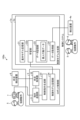
- FIG. 1 is a diagram showing an example of a configuration of a collaborative operation system according to a first embodiment
- FIG. 1 is a diagram showing an example of correction information according to the first embodiment
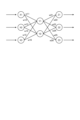
- Schematic diagram showing an example of a neural network A flowchart showing an example of a processing procedure in a control model generating unit according to the first embodiment.
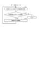
- 1 is a flowchart showing an example of a processing procedure in a robot control unit according to the first embodiment.
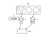
- FIG. 1 is a schematic diagram showing an example of acquiring personal behavior data in a first example
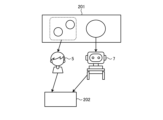
- FIG. 13 is a schematic diagram showing an example of a cooperative operation between a user and a robot in the first example
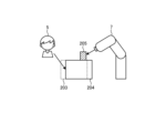
- FIG. 11 is a schematic diagram showing an example of acquiring personal behavior data in the second example
- FIG. 11 is a schematic diagram showing an example of a cooperative operation between a user and a robot in a second example
- FIG. 1 is a diagram showing an example of the configuration of a computer system that realizes a control system according to a first embodiment.
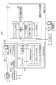
- FIG. 13 is a diagram showing a configuration example of a cooperative operation system according to a second embodiment; A flowchart showing an example of a processing procedure in a control model generating unit according to the second embodiment.
- FIG. 13 is a diagram showing a configuration example of a collaborative operation system according to a third embodiment. A flowchart showing an example of a control model update processing procedure in a control model generating unit according to the third embodiment.
- FIG. 13 is a diagram showing a configuration example of a cooperative operation system according to a fourth embodiment.
- FIG. 13 is a diagram showing a configuration example of a collaborative operation system according to a fifth embodiment.
- FIG. 23 is a diagram showing a configuration example of a cooperative operation system according to a sixth embodiment.
- control model generation device robot control device, control system, control model generation method, and program according to the embodiments are described in detail below with reference to the drawings.
- Embodiment 1. 1 is a diagram showing an example of the configuration of a collaborative operation system according to the first embodiment.
- the collaborative operation system 100 of the present embodiment includes a control system 1, a robot 7, a detection device 4, and a situation detection device 8.
- the collaborative operation system 100 of this embodiment accumulates personal behavior data of the user 5 including collaborative operation data acquired when the robot 7 and the user 5 performed collaborative operation with the collaborative operation target 6 before the collaborative operation between the robot 7 and the user 5 is performed, and generates a control model for controlling the robot 7 using the accumulated personal behavior data.
- the collaborative operation data is personal behavior data acquired while performing collaborative operation.
- the acquired personal behavior data may be only collaborative operation data, or may include other than collaborative operation data.
- the collaborative action includes, but is not limited to, at least one of, for example, conversation, work, games, and sports.
- the collaborative action target 6 is another person who performs a collaborative action with the user 5 and is familiar with the user 5 in the collaborative action.
- a person who is familiar with the user 5 in the collaborative action is, for example, a person who is not meeting the user for the first time and knows at least a little about the other person's personality or speech and behavior habits, and therefore, the user 5 feels that they are compatible in the collaborative action and is less likely to feel stressed when the user 5 performs a collaborative action together.
- the collaborative action target 6 may be determined, for example, by the user 5, or may be determined by an operator of the collaborative action system 100 other than the user 5.
- the collaborative action target 6 When determined by an operator of the collaborative action system 100, for example, a person who is clearly performing a collaborative action with the user 5 for a long period of time is determined as the collaborative action target 6.
- the collaborative action target 6 may be one person or multiple people.
- personal behavior data is acquired that includes collaborative action data when the user 5 collaborates with each of the collaborating action targets 6.
- the collaborating action targets 6 include a first collaborating action target and a second collaborating action target
- the personal behavior data of the user 5 includes collaborative action data acquired during collaboration between the first collaborating action target and the user 5, and collaborative action data acquired during collaboration between the second collaborating action target and the user 5.
- the personal behavior data is data on the behavior of a person who has performed a cooperative action, and in this embodiment, since the personal behavior data of user 5 is acquired, the personal behavior data is data reflecting the personality of user 5. Since the personal behavior data of user 5 includes data acquired when user 5 is performing a cooperative action with a cooperative action target 6 with which user 5 is familiar, it can also be said that the data indirectly reflects the personality of the cooperative action target 6. Furthermore, since the control model is generated using personal data including data of user 5 acquired when user 5 is performing a cooperative action with a cooperative action target 6 with which user 5 is familiar, the personality of user 5 is reflected in the control model.
- the personality of user 5 reflected in the control model is not simply the personality of user 5, but the personality of user 5 when performing a cooperative action with a cooperative action target 6 with which user 5 is familiar, so not only the personality of user 5 but also the personality of the cooperative action target 6 with which user 5 is familiar is indirectly reflected in the control model.
- the indirectly reflected control refers to control that reflects the behavior or manner of speech of the collaborative action target 6 when interacting with the user 5, and can be said to be control that includes elements that are characteristic of the behavior or manner of speech that constitute the individuality of the collaborative action target 6. This allows the robot 7 to perform actions that do not cause stress to the user 5 when performing collaborative actions.
- the personal behavior data is data including the behavioral habits of the user 5.
- the behavior is assumed to be the object to be used for controlling the robot 7, and may include not only the movement but also at least one of the user 5's way of speaking and the position and posture of the user 5. That is, the behavior includes, for example, at least one of the movement, the speech, and at least one of the position and posture of the user 5.
- the movement may not only indicate a continuous movement, but may also include at least one of the position and posture at a certain moment.
- the behavioral habits include at least one of the movement habits and the speech habits.
- the movement habits are, for example, at least one of the movement habits such as the movement trajectory and the movement speed, gestures, etc.
- the speech habits are, for example, at least one of the speaking speed, catchphrases, speaking style, intonation, dialect, etc., but are not limited to these.
- the movements, actions, speaking styles, habits, etc. of the user 5, the collaborative operation target person 6, and the robot 7 may be called behavior.
- the robot 7 is an example of a humanoid that operates in cooperation with the user 5. It should be noted that a humanoid may also be referred to as a controlled object. More specifically, in this embodiment, the robot 7 is an example of a machine that operates in cooperation with the user 5.
- the robot 7 may be humanoid, a machine that does not have any moving parts and only communicates with the user 5, an industrial machine equipped with a manipulator or the like, or something other than these, and there are no particular restrictions on its shape or function.
- the control system 1 controls the robot 7.
- the control system 1 includes a control model generation unit 2 that generates a control model of the robot 7, and a robot control unit 3 that controls the robot 7 using the control model generated by the control model generation unit 2 and situation data detected by a situation detection device 8.
- the control model generation unit 2, which is a control model generation device, and the robot control unit 3, which is a robot control device, may be integrated together, or each may be provided separately.
- the detection device 4 detects the behavior of the user 5 when the user 5 is performing a cooperative action with the cooperative action target 6 as personal behavior data, and transmits the personal behavior data to the control model generation unit 2.
- the detection device 4 is, for example, a device that detects at least one of the position, speed, acceleration, posture, voice, pulse, blood pressure, body temperature, emotion, etc., and there may be multiple detection devices 4.
- the detection device 4 may also detect psychological or internal information, such as biometric information or emotions, of the user 5 when the user 5 is performing a cooperative action with the cooperative action target 6, and include the information in the personal behavior data and transmit it to the control model generation unit 2.
- psychological or internal information such as biometric information or emotions
- the detection device 4 may be a wearable terminal that the user 5 can wear, or a mobile terminal that the user 5 can carry.
- the detection device 4 may also be a device installed so as to be able to detect the motion of the user 5, or a device that detects motion in a virtual space such as the metaverse.
- the detection device 4 may be a combination of these, or may be something else.
- the detection device 4 may be a terminal capable of detecting at least one of its own position, speed, and acceleration, a terminal capable of detecting its own rotation, a terminal equipped with a microphone capable of collecting and recording sound, or a combination of these.
- a GPS (Global Positioning System) receiver, an RFID (Radio Frequency IDentification) tag, or other devices may be used to detect the position of the wearable terminal.
- a wearable terminal or a mobile terminal is used as the detection device 4, it is possible to obtain personal behavior data of the user 5 on a daily basis, not limited to the position of the user 5.
- the detection device 4, the control model generation unit 2, or a device not shown in FIG. 1 performs voice recognition processing to extract the voice of the user 5.
- the voice recognition processing may be any type of processing, but may also be, for example, a process in which the voice of the user 5 is acquired in advance and the voice made by the user 5 is identified using the previously acquired voice.
- the device When a device installed so as to be able to detect the movements of the user 5 is used as the detection device 4, the device may be, for example, a photographing device such as a camera that photographs the location where the coordinated movements are performed, or a device such as a microphone that can collect and record sound at the location where the coordinated movements are performed, or a combination of these.
- the detection device 4 is a photographing device
- the control model generation unit 2 or a device not shown in FIG. 1 recognizes the user 5 in the video photographed by the photographing device, and detects the position, speed, acceleration, movement trajectory, etc. of the user 5.
- the method of recognizing the user 5 may be a general image recognition method, such as using an image of the user 5 photographed in advance.
- the detection device 4 may also recognize the user 5 and detect the position, speed, acceleration, movement trajectory, etc. of the user 5. General methods may also be used for detecting the position, speed, acceleration, movement trajectory, etc. of the user 5.
- the detection device 4 is a device that detects movements in a virtual space such as the metaverse
- the device may be, for example, a computer system that manages the virtual space, a terminal device that the user 5 uses to make his or her avatar move in the virtual space, or a device that records images in the virtual space.
- the control model generation unit 2 or a device not shown in FIG. 1 recognizes the user 5 in the image captured by the imaging device, and detects the position, speed, acceleration, movement trajectory, etc. of the user 5.
- the detection device 4 may include a device that detects the force that the user 5 applies to the object.
- the control model generation unit 2 includes a basic model storage unit 21, a learning unit 22, a data storage unit 23, a data acquisition unit 24, and a correction information storage unit 25.
- the basic model storage unit 21 stores a predetermined basic control model that serves as a reference for the control model for controlling the robot 7.
- the basic control model is a general control model that does not depend on the user 5, i.e., does not reflect the individuality of the user 5, and is a model that defines the basic operations of the robot 7.
- the basic control model may be stored in advance in the data storage unit 23 by the vendor of the control system 1 or the vendor of the robot 7, or may be transmitted from another device, received by a communication unit not shown in FIG. 1, and stored in the data storage unit 23.
- the user 5 may operate the control system 1, which causes the control system 1 to receive a basic control model from an external server that provides a basic control model corresponding to the robot 7.
- the basic control model may be provided for each type of robot 7, or may be provided according to the type of cooperative movement performed by the robot 7.
- a basic control model corresponding to the type of cooperative movement performed by the robot 7 may be stored in the basic model storage unit 21, and the user 5 may select a basic control model corresponding to the type of cooperative movement performed by the robot 7 and the user 5.
- an external server may provide a basic control model corresponding to the type of cooperative movement performed by the robot 7, and the user 5 may select and download a basic control model corresponding to the type of cooperative movement performed by the robot 7 and the user 5, thereby storing the basic control model in the basic model storage unit 21.
- the basic control model and the control model include, for example, one or more control parameters for controlling the robot 7.
- the control parameters include at least one of the following: parameters for controlling the movement of the robot 7, such as the trajectory, speed, and acceleration of the robot 7; parameters for controlling the movement of each part of the robot 7, such as the hands and joints of the robot 7; and parameters for controlling the way the robot 7 speaks, such as the speaking speed of the robot 7 and the pitch (frequency) of the voice emitted by the robot 7.
- the data acquisition unit 24 acquires the personal behavior data of the user 5 from the detection device 4 and stores the acquired personal behavior data in the data storage unit 23.
- processing such as image processing of the video acquired by the detection device 4 and voice recognition processing of the voice acquired by the detection device 4 may be performed.
- other devices not shown
- the data acquisition unit 24 acquires the personal behavior data from the other devices.
- the data acquisition unit 24 may also perform extraction processing such as image processing of the video acquired by the detection device 4 and voice recognition processing of the voice acquired by the detection device 4.
- the data acquisition unit 24 may perform extraction processing on the data acquired from the detection device 4 and store the processed data in the data storage unit 23 as personal behavior data, or the data itself acquired from the detection device 4 may be stored in the data storage unit 23 as personal behavior data, and the learning unit 22 may perform extraction processing in the process of generating a control model described later.
- the data acquisition unit 24 acquires the personal behavior data by receiving the personal behavior data, but this is not limited to this, and the personal behavior data may be recorded on a recording medium or the like. In this case, the data acquisition unit 24 acquires personal behavior data by reading the personal data from the recording medium.
- the correction information storage unit 25 stores correction information indicating correction contents for the basic control model according to the personal behavior data.
- the correction information is, for example, information that associates one or more feature amounts indicated by the personal behavior data with the correction contents.
- the feature amount indicates the personality of the person from whom the personal behavior data is acquired.
- the personality includes, for example, at least one of behavior, catchphrases, intonation, dialect, and movement habits.
- the correction contents are determined according to the personality of the user 5 so that the robot 7 performs an action that does not cause stress to the user 5 when performing a cooperative action with the robot 7.
- the learning unit 22 uses the personal behavior data stored in the data storage unit 23, i.e., the accumulated personal behavior data, to generate a control model of the robot 7 for performing a cooperative action with the user 5, which reflects the personality of the user 5.
- the learning unit 22 generates a control model using, for example, the basic control model stored in the basic model storage unit 21, the personal behavior data accumulated in the data storage unit 23, and the correction information stored in the correction information storage unit 25.
- the personality of the user 5 is classified into types based on N (N is an integer equal to or greater than 1) feature amounts, and the correction information includes correction contents of parameters (control parameters) in the control model for each type.
- the feature amount may be an angle indicating the direction of movement of the user 5 during cooperative movement from a reference direction, or a numerical value indicating the amount of movement from a reference point during cooperative movement of the user 5, or information obtained by frequency-converting time-series data of the position of the user 5 during cooperative movement, or the speaking speed of the user 5, or information obtained by frequency-converting the voice of the user 5.
- the feature amount may be whether or not the user 5 has performed a specific predetermined movement, or the number of times the user 5 has performed a specific predetermined movement per unit time, or whether or not the user 5 has uttered a specific word, or the number of times a specific word has been uttered by the user 5 per unit time, etc.
- a feature amount indicating the habits or personality of the user 5 for example, behaviors that tend to differ from person to person and that show a specific regularity may be extracted.
- the feature amount may be the individual behavior data itself, or the collaborative action data in the individual behavior data itself.
- the feature amount is not limited to the above example, and may be anything that indicates at least one of the characteristics of the user 5's way of moving and speaking, that is, the habits of the user 5. Note that while FIG. 2 shows an example in which N is 3 or more, this is not limiting, and N may be 1 or more.
- the learning unit 22 extracts features from the personal behavior data stored in the data storage unit 23, identifies a type corresponding to the extracted features using the correction information, extracts correction content corresponding to the identified type from the correction information, and generates a control model by correcting the basic control model based on the extracted correction content.
- the correction information may be determined manually in advance.
- the correction information may be determined by a vendor or administrator of the robot 7 or the control system 1, or may be determined by learning through machine learning (pre-learning).
- the vendor or administrator determines the modification information by inferring how the robot 7's behavior based on the basic control model should be modified for each type of user 5 according to the content of the collaborative behavior so that the user 5 does not feel stressed.
- the robot 7 is made to perform a cooperative action with an arbitrary person, and for each cooperative action, a set of data is obtained that includes feature amounts extracted from the personal behavior data of the person who performed the cooperative action and the correction contents of each control parameter in the control model of the robot 7 (correction contents from the basic control model).
- an evaluation is performed to indicate whether or not the person who performed the cooperative action with the robot 7 felt stress.
- the person who performs the cooperative action at this time does not have to be the robot 7 itself that performs the cooperative action with the user 5, but may be another robot of the same type as the robot 7, or may be a different type of robot that can perform the same action as the robot 7.
- a trained model is generated by supervised learning using the correction contents of each control parameter in the data set in which the evaluation result that no stress was felt was obtained by pre-learning as correct data.
- Pre-learning may be performed by the learning unit 22, a pre-learning unit (not shown) of the control model generation unit 2, or a learning device separate from the control system 1.
- the correction information is a trained model for inferring the correction contents of the control parameters from the features extracted from the personal behavior data, and the learning unit 22 can infer the correction contents of the control parameters suitable for the user 5 by inputting the features extracted from the personal behavior data of the user 5 into the trained model.
- the learning unit 22 generates a control model by reflecting the inferred correction contents in the basic control model.
- a neural network is composed of an input layer consisting of multiple neurons, an intermediate layer (hidden layer) consisting of multiple neurons, and an output layer consisting of multiple neurons.
- the intermediate layer can be one layer, or two or more layers.
- Figure 3 is a schematic diagram showing an example of a neural network.
- a three-layer neural network as shown in Figure 3, when multiple inputs are input to the input layer (X1-X3), the values are multiplied by weight W1 (w11-w16) and input to the intermediate layer (Y1-Y2), and the result is further multiplied by weight W2 (w21-w26) and output from the output layer (Z1-Z3).
- W1 weight 11-w16
- Y1-Y2 intermediate layer
- W2 w21-w26
- This output result changes depending on the value of weight W1 and the value of weight W2.
- the weights W1 and W2 are adjusted so that the output from the output layer when the feature extracted from the individual behavior data is input approaches the correction content of the control parameter, which is the correct data, and the relationship between the feature and the correct data is learned.
- the machine learning algorithm is not limited to a neural network, and may be other algorithms such as a support vector machine.
- the machine learning used to generate the trained model is not limited to supervised learning, and may be reinforcement learning, etc.
- information in table format may be used as correction information.
- information in table format may be used as correction information.
- multiple input data are generated by changing the values of each feature, and control parameters obtained by inputting each input data into the trained model are inferred.
- Input data in which the correction contents of the control parameters obtained by inference are all the same or the difference is within a certain range may be defined as one type, control parameters for each type may be determined, and correction information in table format as shown in FIG. 2 may be generated.
- the movement of the robot 7 and the person who performs the cooperative movement may be appropriately changed to obtain multiple data sets with different conditions, and correction information may be determined using the obtained data sets and the corresponding evaluation results.
- the values of the type classification thresholds X1, X2, etc. and the control parameters may be manually determined using the correction contents of each control parameter in a data set in which the evaluation result that no stress was felt is obtained and the feature amounts of the personal behavior data.
- the cooperative action is an action in which the robot 7 and the user 5 cooperate to pull an object with a certain force
- the cooperative action will fail unless the robot 7 increases the pulling force, which will cause stress for the user 5.
- the cooperative action will fail unless the robot 7 decreases the pulling force, which will cause stress for the user 5.
- the pulling force of the user 5 is acquired as individual behavior data, and the total force is defined as overall information. Then, the learning unit 22 calculates the pulling force of the robot 7 by subtracting the pulling force of the user 5 from the total force, and calculates the correction amount of the control parameter according to the calculated force.
- the above-mentioned overall information is one example, and the overall information is not limited to the above-mentioned example.
- the learning unit 22 outputs the generated control model to the robot control unit 3.
- the robot control unit 3 includes an instruction sending unit 31, a situation acquisition unit 32, a control instruction generating unit 33, and a control model storage unit 34.
- the robot control unit 3 is an example of a motion control unit (motion control device) that controls a humanoid.
- the control model storage unit 34 stores the control model output from the learning unit 22.
- the situation acquisition unit 32 acquires situation data indicating the situation of the cooperative operation between the robot 7 and the user 5 acquired by the situation detection device 8 by receiving it from the situation detection device 8, and outputs the acquired situation data to the control instruction generation unit 33.
- the situation detection device 8 may be provided on the robot 7, may be provided in the vicinity of the robot 7, or may be provided on both the robot 7 and the vicinity of the robot 7.
- the situation detection device 8 acquires situation data used for controlling the robot 7 according to the type of robot 7 and the content of the cooperative operation.
- the situation detection device 8 may acquire the situation of the operation of the user 5, such as the voice uttered by the user 5 and the movement of the user 5. There may be multiple situation detection devices 8.
- the situation detection device 8 may be, for example, a photographing device that detects the position of the robot 7, the state of the surroundings of the robot 7, etc., or may be an acceleration sensor, a force sensor, etc. Furthermore, the situation detection device 8 may be a photographing device for grasping the positional relationship between the target object and the robot 7 when the robot 7 moves the target object or applies a force to the target object.
- the situation detection device 8 may be two or more of these, or may be other than these, and any sensor generally used for controlling the robot 7 may be used. Note that situation data does not need to be used for controlling the robot 7, in which case the situation detection device 8 does not need to be provided.
- the control instruction generation unit 33 generates control instructions for the robot 7 using the situation data received from the situation acquisition unit 32 and the control model stored in the control model storage unit 34, and outputs the generated control instructions to the instruction transmission unit 31.
- the instruction transmission unit 31 transmits the control instructions received from the control instruction generation unit 33 to the robot 7.
- the robot 7 that receives the control instructions operates based on the control instructions.
- the learning unit 22 generates a control model using personal behavior data from when the user 5 is performing a cooperative action with the familiar cooperative action target 6, and a control instruction based on the generated control model is transmitted to the robot 7. Because the control model is generated before the cooperative action between the user 5 and the robot 7, the robot 7 can perform actions that are the same as or similar to the actions of the cooperative action target 6 from the start of the cooperative action, thereby reducing stress on the user 5 caused by at least one of the actions and speech of the robot 7 during the cooperative action.
- FIG. 4 is a flowchart showing an example of a processing procedure in the control model generation unit 2 of this embodiment.
- the control model generation unit 2 acquires personal behavior data of the user 5 including cooperative action data acquired during cooperative action between the user 5 and the cooperative action target 6 (step S1).
- the data acquisition unit 24 acquires the personal behavior data of the user 5 by receiving the personal behavior data from the detection device 4.
- the data acquisition unit 24 may acquire the personal behavior data by a recording medium. Also, video or the like that is the source of the personal behavior data may be acquired by the detection device 4 and extraction processing may be performed.
- the control model generation unit 2 stores the personal behavior data of the user 5 (step S2).
- the data acquisition unit 24 stores the received personal behavior data in the data storage unit 23.
- the control model generating unit 2 generates a control model using the accumulated individual behavior data (step S3).
- the learning unit 22 extracts a feature value using the individual behavior data of the user 5 stored in the data storage unit 23, and generates a control model using the feature value and the basic control model stored in the basic model storage unit 21.
- the accumulated individual behavior data is individual behavior data acquired for each cooperative action in one or more cooperative actions. If the feature value is, for example, the speaking speed of the user 5, when individual behavior data corresponding to multiple cooperative actions are accumulated, the average speed per character may be obtained using all the individual behavior data corresponding to the multiple cooperative actions.
- the individual behavior data corresponding to the multiple cooperative actions may be used to calculate an average position at a specified time point in the cooperative action, and the difference between the average position and a predetermined standard position may be used as the feature value.
- the method of calculating the feature value is not limited to the above example.
- the control model generation unit 2 outputs the control model (step S4).
- the learning unit 22 outputs the generated control model to the robot control unit 3.
- the control model storage unit 34 of the robot control unit 3 stores the control model output from the learning unit 22.
- FIG. 5 is a flowchart showing an example of a processing procedure in the robot control unit 3 of this embodiment. The processing shown in FIG. 5 is performed when the robot 7 and the user 5 perform a cooperative operation after the control model is generated by the control model generation unit 2.
- the robot control unit 3 acquires situation data (step S11).
- the situation acquisition unit 32 acquires situation data indicating the situation of the robot 7 acquired by the situation detection device 8 by receiving the situation data from the situation detection device 8, and outputs the acquired situation data to the control instruction generation unit 33.
- the robot control unit 3 generates a control instruction using the situation data and the control model (step S12).
- the control instruction generation unit 33 generates a control instruction for the robot 7 using the situation data received from the situation acquisition unit 32 and the control model stored in the control model storage unit 34, and outputs the generated control instruction to the instruction transmission unit 31.
- the robot control unit 3 transmits a control instruction (step S13).
- the instruction transmission unit 31 transmits the control instruction received from the control instruction generation unit 33 to the robot 7.
- the robot 7 performs an operation based on the control instruction.
- the cooperative operation is serving food.
- A, B, C, and D all work at the same restaurant, and B sometimes serves food with A, sometimes serves food with C, and sometimes serves food with D.
- B is able to perform a good job when serving food with A, and also when serving food with C.
- B is unable to perform the serving task comfortably and feels stressed.
- a and C are planning to retire, and after A and C retire, B is scheduled to perform the serving task with the robot 7.
- FIG. 6 is a schematic diagram showing an example of acquiring personal behavior data in the first example.
- user 5 and collaborative action target 6 serve plates placed on a serving counter 201 to tables 202 in the dining area of a restaurant.
- personal behavior data of person B is acquired by detection device 4.
- user 5 when user 5 is serving food together with collaborative action target 6, user 5 serves multiple small plates, and collaborative action target 6 serves large plates.
- person D when user 5 is serving food together with person D, person D serves multiple small plates, and person B serves large plates.
- the personal behavior data includes information indicating which dishes were served.
- a detection device 4 may be used to detect the position of the user 5, and the time series data of the positions detected by the detection device 4 may be used as the personal behavior data.
- the learning unit 22 may obtain a history of the movement of the user 5, and obtain the size of the plates served by the user 5 as a feature based on the obtained history and the positions of the small and large plates.
- a detection device 4 capable of photographing the serving counter 201 may be used, and the size and number of plates served by the user 5 may be calculated as personal behavior data by the data acquisition unit 24 or another device by analyzing the image photographed by the detection device 4.
- a detection device 4 capable of photographing the serving counter 201 may be used, and the image photographed by the detection device 4 may be used as personal behavior data, and the learning unit 22 may obtain the size of the plates served by the user 5 as a feature from the image.
- the plates to be served in the serving task include large and small plates.
- the size of the plates to be served, or the size and number of the plates to be served are included as feature quantities, and a type in which multiple small plates are served, or a type in which a large plate is served, are defined as a type in the modification information.
- a numerical value is defined as a control parameter for setting the target of the robot 7 to be a large plate.
- the control model includes a serving judgment model and a movement model
- the serving judgment model includes a definition of the size of the plate to be served by the robot 7.
- a modification content corresponding to the above-mentioned type in the modification information information is defined for setting a control parameter for setting the target of the serving to be a plate with a diameter of a certain value or more.
- This allows the learning unit 22 of the control model generation unit 2 to generate a control model that causes the robot 7 to serve large plates.
- the range of the plates to be served on the serving counter 201 may be defined as a control parameter.
- FIG. 7 is a schematic diagram showing an example of cooperative operation between user 5 and robot 7 in the first example.
- a control model has been generated to cause robot 7 to serve food on a large platter, and so robot 7 serves food on a large platter.
- This allows user 5 to serve food efficiently with less stress, similar to when serving food together with cooperative action target 6, person A or person C.
- control system 1 can learn a method of serving food that allows user 5, person B, to act efficiently, and generate a control model that reflects the results of the learning.
- the robot 7 is, for example, an assembly robot, which is a type of industrial machine.
- Person A, Person B, Person C, and Person D are all workers who perform assembly work, and Person B sometimes performs assembly work with Person A, sometimes performs assembly work with Person C, and sometimes performs assembly work with Person D.
- Person B is able to perform the job well when performing assembly work with Person A, and also when performing assembly work with Person C.
- Person B it is assumed that when Person B performs assembly work with Person D, Person B, who is the user 5, is unable to perform the assembly work comfortably and feels stressed.
- Persons A and C are scheduled to be transferred, and after Person A and C are transferred, Person B is scheduled to perform assembly work with the robot 7.
- individual behavior data including cooperative behavior data when Person B, who is the user 5, performs cooperative behavior with the cooperative behavior target person 6 is acquired.
- the collaborative action targets 6 who are familiar with collaborative action with B are A and C.
- FIG. 8 is a schematic diagram showing an example of acquiring individual behavior data in the second example.
- user 5 and collaborative action target 6 cooperate to perform assembly work. More specifically, user 5 (Mr. B) places first part 204, and collaborative action target 6 (Mr. A or Ms. C) places second part 205 on top of first part 204.
- Standard position 203 indicates the standard position where first part 204 is placed, and user 5 has a habit of placing first part 204 to the right of the standard position in FIG. 8.
- User D who is not familiar with User 5, attempts to place the second part 205 on the assumption that the first part 204 will be placed in the standard position 203, which takes time to align and requires User 5 to change the position of the first part 204, making it difficult to assemble efficiently and causing User 5 to feel stressed.
- the detection device 4 detects the location where the user 5 places the first part 204, or the position of the user 5's hand when the user 5 places the first part 204. Then, using the difference from the standard position 203 of the first part 204 as a feature amount, a type is defined in the correction information that the placement position of the first part 204 is shifted from the standard position 203 by a threshold value or more. Then, as the correction content corresponding to that type in the correction information, content is included that determines a control parameter so that the position of the second part 205 placed by the robot 7 is shifted by the same amount as the difference between the placement position of the first part 204 and the standard position 203. This allows the learning unit 22 of the control model generation unit 2 to generate a control model that causes the robot 7 to place the second part 205 according to the amount by which the user 5 has shifted the first part 204 from the standard position 203.
- FIG. 9 is a schematic diagram showing an example of cooperative operation between user 5 and robot 7 in the second example.
- a control model has been generated that causes robot 7 to place second part 205 in accordance with the amount by which user 5 has shifted first part 204 from standard position 203, so robot 7 places second part 205 shifted to the right. This allows user 5 to reduce stress and perform assembly work efficiently, just as when performing assembly work together with cooperative operation target person 6, Mr. A or Mr. C.
- the robot 7 is able to work together with the user 5, taking into consideration the behavior of the user 5, Mr. B, and even in an environment where humans work together to reduce manpower, with the robot 7, an example of a humanoid, the user 5 can perform cooperative operations with reduced stress, such as difficulty in working and discomfort.
- the cooperative operations performed using the cooperative operation system 100 described above are merely examples, and the cooperative operations performed using the cooperative operation system 100 are not limited to the above examples.
- the cooperative action is not limited to being performed by two people, but may be performed by three or more people.
- two robots 7 may be used, or the robot 7 and the cooperative action target person 6 may perform the cooperative action together with the user 5.
- a control model is generated based on C's personal behavior data, and the robot 7 is controlled based on this control model.
- FIG. 10 is a diagram showing an example of the configuration of a computer system that realizes the control system 1 of this embodiment.
- this computer system includes a control unit 101, an input unit 102, a storage unit 103, a display unit 104, a communication unit 105, and an output unit 106, which are connected via a system bus 107.
- the control unit 101 and the storage unit 103 form a processing circuit.
- control unit 101 is, for example, a processor such as a CPU (Central Processing Unit), and executes a program in which the processing in the control system 1 of this embodiment is described.
- a part of the control unit 101 may be realized by dedicated hardware such as a GPU (Graphics Processing Unit) or an FPGA (Field-Programmable Gate Array).
- the input unit 102 may be an input means such as a button, a keyboard, a mouse, a joystick, a touchpad, or a game controller.
- the storage unit 103 includes various memories such as a RAM (Random Access Memory) and a ROM (Read Only Memory), and a storage device such as a hard disk, and stores the program to be executed by the control unit 101, necessary data obtained in the process of processing, etc.
- the storage unit 103 is also used as a temporary storage area for the program.
- the display unit 104 is, for example, a display, as described above. Note that the display unit 104 and the input unit 102 may be integrated and realized by a touch panel, etc.
- the communication unit 105 is a receiver and a transmitter that perform communication processing.
- the output unit 106 is a speaker or the like. Note that FIG. 10 is an example, and the configuration of the computer system is not limited to the example of FIG. 10. For example, in this embodiment, the computer system that realizes the control system 1 does not need to include the output unit 106.
- a computer program is installed in the storage unit 103 from a CD-ROM or DVD-ROM set in a CD (Compact Disc)-ROM drive or DVD (Digital Versatile Disc)-ROM drive (not shown). Then, when the program is executed, the program read from the storage unit 103 is stored in the main memory area of the storage unit 103. In this state, the control unit 101 executes processing as the control system 1 of this embodiment according to the program stored in the storage unit 103.
- the program describing the processing in the control system 1 is provided on a CD-ROM or DVD-ROM as a recording medium, but this is not limiting.
- a program provided via a transmission medium such as the Internet may be used.
- the program of this embodiment causes a computer system to execute, for example, the steps of accumulating personal behavior data, which is data on the behavior of a person who has performed cooperative actions, and using the accumulated personal behavior data, generating a control model for a humanoid that allows the humanoid to perform cooperative actions with a user 5, the control model reflecting the personality of the person.
- the learning unit 22 and control instruction generation unit 33 shown in FIG. 1 are realized by the control unit 101 shown in FIG. 10 executing a computer program stored in the storage unit 103 shown in FIG. 10.
- the storage unit 103 shown in FIG. 10 is also used to realize the learning unit 22 and control instruction generation unit 33 shown in FIG. 1.
- the data acquisition unit 24, instruction transmission unit 31, and status acquisition unit 32 shown in FIG. 1 are realized by the communication unit 105 shown in FIG. 10.
- the data acquisition unit 24 may also be realized by a device that reads out a recording medium.
- the basic model storage unit 21, data storage unit 23, correction information storage unit 25, and control model storage unit 34 shown in FIG. 1 are part of the storage unit 103 shown in FIG. 10.
- the control system 1 shown in FIG. 1 may be realized by multiple computer systems.
- the control system 1 may be realized by a cloud system.
- the control model generation unit 2 and the robot control unit 3 may each be configured as separate devices, and in this case, each of the separate devices may also be realized by multiple computer systems.
- the collaborative operation system 100 of this embodiment generates a control model for controlling the robot 7 using personal behavior data of the user 5, including collaborative operation data acquired when the user 5 and the collaborative operation target 6 performed collaborative operation, before the collaborative operation between the robot 7 and the user 5 is performed.
- the robot 7 can perform actions that are the same as or similar to the actions of the collaborative operation target 6 from the start of the collaborative operation, and can reduce stress on the user 5 caused by at least one of the actions and speech of the robot 7 during the collaborative operation.
- Embodiment 2. 11 is a diagram showing an example of the configuration of a collaborative system according to the second embodiment.
- a collaborative system 100a according to the second embodiment is similar to the collaborative system 100 according to the first embodiment, except that it includes a control system 1a instead of the control system 1 and a detection device 4a instead of the detection device 4.
- Components having the same functions as those in the first embodiment are given the same reference numerals as those in the first embodiment, and duplicated explanations will be omitted. Below, differences from the first embodiment will be mainly explained.
- a control model is generated using personal behavior data of the user 5, including cooperative action data acquired when the user 5 and the cooperative action target 6 are performing cooperative actions.
- a control model is generated using personal behavior data of the cooperative action target 6, including cooperative action data acquired when the user 5 and the cooperative action target 6 are performing cooperative actions.
- the personal behavior data which is data on the actions of a person who has performed cooperative actions, is the personal behavior data of the cooperative action target 6. That is, the person from whom personal behavior data is acquired is the user 5 in the first embodiment, and the cooperative action target 6 in the present embodiment.
- the cooperative action target 6 is a person with whom the user 5 is familiar, as in the first embodiment, and is a person with whom the user 5 is unlikely to feel stressed when performing cooperative actions together.
- the detection device 4a acquires personal behavior data of the collaborative action subject 6 and transmits the personal behavior data to the control system 1a.
- the personal behavior data may include psychological or internal information such as biological information or emotions of the collaborative action subject 6.
- the detection device 4a is the same as the detection device 4 in the first embodiment, but acquires personal behavior data from the collaborative action subject 6.
- the detection device 4a may be a wearable terminal that can be worn by the collaborative action subject 6, a portable terminal that can be carried by the collaborative action subject 6, a device installed so as to detect the actions of the collaborative action subject 6, a device that detects actions in a virtual space such as the metaverse, a combination of these, or other.
- the personal behavior data includes, for example, at least one of data acquired by a wearable terminal and data recording the actions of a person in a virtual space.
- the control system 1a is similar to the control system 1 of the first embodiment, except that it includes a control model generation unit 2a instead of the control model generation unit 2.
- the control model generation unit 2a does not include a correction information storage unit 25, includes a learning unit 22a instead of the learning unit 22, and the data acquisition unit 24 acquires data from a detection device 4a instead of a detection device 4, but otherwise is similar to the control model generation unit 2 of the first embodiment.
- the control model generation unit 2a and the robot control unit 3 may be provided as separate devices.
- FIG. 12 is a flowchart showing an example of a processing procedure in the control model generating unit 2a of this embodiment.
- the control model generating unit 2a acquires personal behavior data of the collaborating action subject 6 including cooperative action data acquired during cooperative action between the user 5 and the collaborating action subject 6 (step S21).
- the data acquiring unit 24 acquires the personal behavior data of the collaborating action subject 6 by receiving the personal behavior data from the detection device 4a.
- the data acquiring unit 24 may acquire the personal behavior data by a recording medium. Also, video or the like that is the source of the personal behavior data may be acquired by the detection device 4a and extraction processing may be performed.
- the control model generating unit 2a stores the individual behavior data of the collaborative action target 6 (step S22).
- the data acquiring unit 24 stores the received individual behavior data in the data storage unit 23.
- the control model generating unit 2a generates a control model using the accumulated personal behavior data of the collaborative action target 6 (step S23).
- the learning unit 22a extracts features using the personal behavior data of the collaborative action target 6 stored in the data storage unit 23, and generates a control model based on the features.
- control parameters in the control model are set so that the robot 7 performs the action indicated by the feature.
- This generates a control model for making the robot 7 perform the same action as the action reflecting the individuality of the collaborative action target person 6.
- the feature can be the same as that in the first embodiment, but in this embodiment, information about the dialect, speaking habits (including catchphrases), and topics provided (genres that are often spoken) may be used as the feature.
- the information about the dialect includes, for example, information on the presence or absence of a dialect, and if there is a dialect, what type (region) of dialect it is.
- the dialect may be identified, for example, by storing a dictionary of dialects for each type of dialect in advance and using the dictionary, or by other methods.
- the speaking habits may be, for example, the frequent use of a specific word at the end of a sentence, the frequent utterance of a specific word, intonation such as a higher pitch at the end of a sentence, the pitch of the voice, the speed of speech, and the like, but may be other than these.
- the learning unit 22a extracts these speaking habits, for example, by performing voice recognition processing on the voice data obtained as the individual behavior data of the collaborative action target person 6.
- step S24 is the same as in embodiment 1, where the learning unit 22a outputs the generated control model to the robot control unit 3.
- the output control model is stored in the control model storage unit 34 of the robot control unit 3.
- the operation of the robot control unit 3 is the same as in embodiment 1.
- a control model is generated based on the personal behavior data of the collaborative operation target 6 so that the robot 7 performs an operation that reflects the individuality of the collaborative operation target 6. This allows the robot 7 to perform an operation that reflects the individuality of the collaborative operation target 6 that the user 5 is familiar with in collaborative operation with the user 5, and can reduce stress on the user 5 caused by at least one of the behavior and speaking style of the robot 7 in collaborative operation.
- the robot 7 is a communication robot and the cooperative operation is a conversation.
- Mr. A and Mr. B are a married couple, and Mr. B is accustomed to talking with Mr. A and does not feel stressed when talking with Mr. A. Mr. A is scheduled to work alone overseas, and during Mr. A's work alone, Mr. B plans to talk with the robot 7.
- the user 5 of the robot 7 is Mr. B, Mr. A is set as the cooperative operation target person 6, and personal behavior data of Mr. A is acquired.
- the control model generation unit 2a generates a control model based on the accumulated personal behavior data of Mr. A.
- the basic control model includes a conversation model and a voice model, and the conversation model and voice model are modified so as to have characteristics similar to those of Mr. A based on the personal behavior data.
- a control model is generated that reflects, for example, Mr. A's catchphrases, intonation, dialect, way of responding, and topic content.
- robot 7 When user 5, B, converses with robot 7 as a cooperative operation while A is away from home, robot 7 is controlled using a control model based on the personal behavior data of A described above. This allows robot 7 to converse in a way that reflects A's personality, thereby reducing the stress of user 5, B.
- the cooperative operation performed using cooperative operation system 100a described above is merely an example, and cooperative operation performed using cooperative operation system 100a is not limited to the above example.
- the control system 1a of this embodiment is realized by a computer system, similar to the control system 1 of embodiment 1.
- the control system 1a of this embodiment may also be realized by multiple computer systems, for example, by a cloud system.
- the control model generation unit 2a and the robot control unit 3 may each be configured as separate devices, and in this case, each of the separate devices may also be realized by multiple computer systems.
- the cooperative action is not limited to two people, but may be performed by three or more people.
- two robots 7 may be used, or the robot 7 and the cooperative action target 6 may perform a cooperative action together with the user 5.
- a control model is generated based on the personal behavior data of A and C, and the two robots 7 are controlled based on the respective control models.
- the robot 7 and the cooperative action target 6 perform a cooperative action together with the user 5
- the robot 7 may be controlled based on the control model corresponding to C
- the robot 7 may be controlled based on the control model corresponding to A.
- the collaborative operation system 100a of this embodiment generates a control model for controlling the robot 7 using personal behavior data of the collaborative operation target 6, including collaborative operation data acquired when the user 5 and the collaborative operation target 6 performed collaborative operation, before the collaborative operation between the robot 7 and the user 5 is performed.
- the robot 7 can perform actions that are the same as or similar to the actions of the collaborative operation target 6 from the start of the collaborative operation, and can reduce stress on the user 5 caused by at least one of the actions and speech of the robot 7 during the collaborative operation.
- Embodiment 3. 13 is a diagram showing an example of the configuration of a collaborative system according to the third embodiment.
- a collaborative system 100b according to the third embodiment is similar to the collaborative system 100a according to the second embodiment, except that a control system 1b is provided instead of the control system 1a.
- Components having the same functions as those in the second embodiment are given the same reference numerals as those in the second embodiment, and duplicated explanations will be omitted. Below, differences from the second embodiment will be mainly explained.
- Control system 1b is similar to control system 1a of embodiment 2, except that it has control model generation unit 2b instead of control model generation unit 2a.
- Control model generation unit 2b has an action result acquisition unit 26 added, and has learning unit 22b instead of learning unit 22a, but other than that it is similar to control model generation unit 2a of embodiment 2.
- control model generation unit 2b and robot control unit 3 may be provided as separate devices.
- control model generation unit 2b updates the control model based on the behavior result, which is the result of the cooperative action performed by the robot 7 and the user 5, and the control model corresponding to the behavior result.
- the control model is generated so as to reduce the stress of the user 5, but in this embodiment, the behavior of the robot 7 can be made more suitable for the user 5 by updating the control model using the behavior result.
- FIG. 14 is a flowchart showing an example of a control model update processing procedure in the control model generation unit 2b of this embodiment.
- the control model generation unit 2b acquires an action result corresponding to the control model (step S31).
- the action result acquisition unit 26 acquires an action result corresponding to a cooperative action (cooperative action between the robot 7 and the user 5) performed by control based on the control model stored in the robot control unit 3, and outputs the acquired action result to the learning unit 22b.
- the behavior result indicates, for example, whether a positive result or a negative result has been obtained.
- the behavior result is determined, for example, by the user 5 and input to the control model generation unit 2b.
- the behavior result acquisition unit 26 has a function of accepting input from the user 5.
- the user 5 may input the behavior result to another device, such as a user terminal (not shown), and the other device may transmit the behavior result to the control model generation unit 2b.
- the behavior result acquisition unit 26 has a communication function for receiving the behavior result.
- the behavior result is determined to be a positive result
- the behavior result is determined to be a negative result
- the behavior result may be determined by another means.
- the task time may be measured, and if the measurement result is below a threshold, a person other than the user 5 may determine that the task was performed efficiently and the behavior result may be a positive result, and if the measurement result exceeds the threshold, the task may be determined that the task was not performed efficiently and the behavior result may be a negative result.
- the behavior result may be input to the control model generation unit 2b or may be transmitted from another device. If the task is performed efficiently, it can be estimated that the stress on the user 5 is low, so the behavior result may be determined based on the measurement result of the task time in this way.
- the control model generation unit 2b may also make a judgment based on the above-mentioned measurement result.
- the behavior result acquisition unit 26 may receive the measurement result from a device that measures the task time and determine the behavior result using the received measurement result.
- the method of determining the behavior result is not limited to the above-mentioned example.
- the control model generating unit 2b determines whether the behavior result is a negative result (step S32).
- the learning unit 22b determines whether the behavior result received from the behavior result acquiring unit 26 is a negative result.
- step S32 No If the behavioral result is not a negative result (step S32 No), i.e., if the behavioral result is a positive result, the control model generation unit 2b ends the control model update process.
- step S33 the control model generation unit 2b updates the control model (step S33) and repeats the process from step S31.
- the learning unit 22b updates the control model and outputs the updated control model to the robot control unit 3. This updates the control model stored in the control model storage unit 34 of the robot control unit 3.
- the learning unit 22b updates the control model, for example, by changing some of the control parameters in the control model.
- the method of changing the control parameters may be determined in advance or may be specified by the user 5. For example, when updating a control parameter that changes the position of the robot 7, a rule for changing the position of the robot 7 may be determined in advance, or the user 5 may specify the direction and amount of change regarding the position of the robot 7.
- the control model is updated, control is performed using the updated control model, and processing is performed again from step S31. If the behavioral result is a negative result, the control parameters are repeatedly changed until a positive result is obtained as the behavioral result.
- the control model when the behavior result is a positive result, the control model is not changed and the current control model is used as the updated control model.
- the control model may be updated by changing the current control parameter to a control parameter that is estimated to be better.
- the control parameter that is estimated to be better is, for example, a control parameter that is changed in the opposite direction to the control parameter that was set when the behavior result was previously a negative result. For example, if the conversation speed is a first speed, the behavior result is negative, and changing the conversation speed to a second speed slower than the first speed results in a positive behavior result, the control model may be updated to change the conversation speed to a third speed slower than the second speed. Then, the behavior result is obtained again, and if the behavior result is negative, the control model is updated to return the conversation speed to the second speed.
- control model update process is not limited to the procedure shown in FIG. 14, and the control parameters may be changed sequentially to obtain action results corresponding to the values of the control parameters, a data set of the control parameter values and the corresponding action results may be stored, and the control model may be updated using the multiple data sets.
- the data sets in which the action results were positive may be extracted, one of the extracted data sets may be selected, and the control model may be updated using the control parameters in the selected data set.
- the control model may also be updated by determining control parameters that improve the action results by machine learning using multiple data sets, with the action results and the corresponding control parameters as a set of data sets.
- the learning unit 22b uses multiple data sets consisting of the action results and the control parameters that are the corresponding correct answer data to generate a learned model by the supervised learning described in the first embodiment. Then, at the time of inference, i.e., at the time of updating the control model, the learning unit 22b can infer control parameters that will result in a positive action result by inputting a value that will result in a positive action result as the action result.
- the behavioral result is not limited to the binary values of positive and negative, but may be expressed as a number with three or more levels.
- the behavioral result may be scored from 0 to 5, and a behavioral result of 5 may be defined as the least stressful for user 5, and a behavioral result of 0 may be defined as the most stressful for user 5.
- the definition of the score is not limited to this example.
- the learning unit 22b may determine whether the number indicates that the behavioral result is the most positive. Furthermore, when updating the control model using the above-mentioned multiple data sets, the learning unit 22b may select a data set with a number indicating that the behavioral result is the most positive.
- the behavior result was the result of evaluating the entire control model, but it is not limited to this, and may be the result of evaluating the time-series movements of the robot 7 in sections.
- the control instructions to the robot 7 may be recorded in an operation history storage unit (not shown), and the behavior result may be determined, for example, at regular intervals or for each section of the robot 7's movements.
- the operation history storage unit may be provided in the robot control unit 3, in the control model generation unit 2b, or outside the control system 1b.
- the behavior result acquisition unit 26 reads and acquires the control instructions for the period corresponding to the behavior result from the operation history storage unit together with the behavior result, and outputs the behavior result and the corresponding control instructions to the learning unit 22b. In this way, the learning unit 22b can obtain the behavior result of the movement in units of the movement of the robot 7 corresponding to the control instructions performed in the time series.
- the collaborative action is a conversation
- a result is obtained based on the individual behavior data of the collaborative action target 6 that the collaborative action target 6 often provides topics about the first and second genres as a feature of the collaborative action target 6, and a control model is generated based on this result.
- the frequency of providing topics of the first and second genres is set to be approximately the same.
- the time series includes a period in which the conversation of the first genre takes place and a period in which the conversation of the second genre takes place. These periods are distinguished based on a control instruction to the robot 7, and the behavior result of each is acquired by the behavior result acquisition unit 26.
- control model is updated to increase the frequency of providing topics of the first genre and decrease the frequency of providing topics of the second genre.
- the control model update process is not limited to the above example, and may be any method in which the learning unit 22b updates the control model based on the behavioral results so that the control model becomes more suitable for the user 5.
- the control system 1b of this embodiment is realized by a computer system, similar to the control system 1a of the second embodiment.
- the control system 1b of this embodiment may also be realized by multiple computer systems, for example, by a cloud system.
- the control model generation unit 2b and the robot control unit 3 may each be configured as separate devices, and in this case, each of the separate devices may also be realized by multiple computer systems.
- the collaborative operation system 100b of this embodiment performs the operations described in embodiment 2, and updates the control model based on the behavioral results that are the results of the collaborative operation between the robot 7 and the user 5. This provides the same effects as embodiment 2, and allows the robot 7 to perform operations that are more suitable for the user 5.
- a control model update function is added to the collaborative operation system 100a of embodiment 2, but this is not limiting, and a control model update function may be added to the collaborative operation system 100 of embodiment 1.
- the control model may be updated in the same manner as in the above example by adding an action result acquisition unit 26 to the control model generation unit 2 of the collaborative operation system 100 and providing the learning unit 22 with a control model update function similar to the learning unit 22b.
- Embodiment 4. 15 is a diagram showing an example of the configuration of a collaborative system according to the fourth embodiment.
- a collaborative system 100c according to the fourth embodiment is similar to the collaborative system 100b according to the third embodiment, except that a control system 1c is provided instead of the control system 1b.
- Components having the same functions as those in the third embodiment are given the same reference numerals as those in the third embodiment, and duplicated explanations will be omitted. Below, differences from the third embodiment will be mainly explained.
- the control system 1c is similar to the control system 1b of the third embodiment, except that it has a control model generation unit 2c instead of the control model generation unit 2b.
- the control model generation unit 2c has an additional model selection receiving unit 27 and a basic model storage unit 21a instead of the basic model storage unit 21, but is otherwise similar to the control model generation unit 2b of the third embodiment.
- the control model generation unit 2c and the robot control unit 3 may be provided as separate devices.
- the basic model storage unit 21a stores a plurality of basic control models, i.e., a plurality of types of basic control models, in advance. These plurality of types of basic control models can be said to be typical patterns that characterize the collaborative action target 6.
- a typical pattern that characterizes the collaborative action target 6 is a pattern that corresponds to speech and actions (behavior) based on a typical human personality, such as being impatient, easygoing, or meticulous.
- the collaborative action includes a conversation
- three basic control models, a moderate model, a solid model, and a leading model are stored in the basic model storage unit 21a.
- the moderate model, solid model, and leading model each differ in at least one of, for example, the content of the conversation, the speed of the conversation, the frequency of speaking, and the genre of the topic provided.
- the basic model storage unit 21a stores basic control models that behave in a manner that is based on typical work content that requires consideration for people working together, such as collaborative design work using engineering tools, collaborative precision work such as medical procedures (surgery), or collaborative work for long periods of time such as installing large equipment.
- the basic control models i.e., typical patterns
- the multiple control models may be classified based on typical characteristics of other objects that perform coordinated operations.
- the multiple control models each correspond to a different personality (personality of operation).
- the multiple basic control models are not limited to this example, and the number of basic control models is not limited to three.
- the model selection receiving unit 27 receives from the user 5 a selection result indicating the basic control model selected by the user 5 from among the multiple basic control models.
- the model selection receiving unit 27 may receive an input of the selection result from the user 5.
- the user 5 may input the selection result to another device such as a user terminal (not shown), which may transmit the selection result to the control model generating unit 2c, and the model selection receiving unit 27 may receive the selection result, thereby receiving the selection result of the basic control model.
- the user 5 selects a basic control model from among the multiple basic control models according to taste and compatibility.
- the user 5 may select a basic control model that matches the collaborative motion target 6 from among the multiple basic control models.
- the moderate model may be selected.
- the control system 1c or an operator of the control system 1c may select the basic control model suitable for the collaborative action target person 6.
- the model selection receiving unit 27 reads out the basic control model corresponding to the received selection result from the basic model storage unit 21a, and outputs the read basic control model to the learning unit 22b.
- the learning unit 22b uses the basic control model received from the model selection receiving unit 27, i.e., the basic control model indicated by the selection result, and the personal behavior data to generate a control model, as in the third embodiment, and outputs the generated control model to the robot control unit 3. Also, the learning unit 22b updates the control model using the behavior result, as in the third embodiment.
- the operation of this embodiment other than as described above is the same as in the third embodiment.
- the control system 1c of this embodiment is realized by a computer system, similar to the control system 1b of the third embodiment.
- the control system 1c of this embodiment may also be realized by multiple computer systems, for example, by a cloud system.
- the control model generation unit 2c and the robot control unit 3 may each be configured as separate devices, and in this case, each of the separate devices may also be realized by multiple computer systems.
- the collaborative operation system 100c of this embodiment generates a control model using a basic control model selected from a plurality of basic control models with different movement characteristics and personal behavior data. Furthermore, the collaborative operation system 100c of this embodiment updates the control model based on the behavioral results that are the result of collaborative operation between the robot 7 and the user 5. This provides the same effects as the third embodiment, and also makes it possible to cause the robot 7 to perform actions that are more in line with the preferences and compatibility of the user 5.
- the collaborative operation system 100b of the third embodiment is added with a function of generating a control model using a basic control model selected from a plurality of basic control models, but this is not limited to the above.
- a function of generating a control model using a basic control model selected from a plurality of basic control models may be added to the collaborative operation system 100 of the first embodiment.
- a control model may be generated using a basic control model selected from a plurality of basic control models as in the above example.
- a function of generating a control model using a basic control model selected from a plurality of basic control models may be added to the collaborative operation system 100a of the second embodiment.
- a control model may be generated using a basic control model selected from a plurality of basic control models as in the above example.
- Embodiment 5 is a diagram showing a configuration example of a collaborative system according to a fifth embodiment.
- a collaborative system 100d includes a control system 1d, a detection device 4, and a situation detection device 8a.
- the control system 1d generates a virtual space such as a metaverse, and transmits virtual space information to a terminal device 94 for allowing a user 5 to perceive the virtual space.
- the terminal device 94 outputs an image in the virtual space to an image presentation device 95 based on the virtual space information received from the control system 1d, and outputs an audio in the virtual space to an audio presentation device 96.
- the user 5 collaborates with a virtual character 902 via his or her own avatar 901 in the virtual space.
- a robot 7 is given as an example of a humanoid that cooperates with a user 5, but in this embodiment, an example will be described in which the humanoid that cooperates with a user 5 is a virtual character 902 in a virtual space.
- the virtual character 902 is controlled using a control model generated based on personal behavior data of the user 5 acquired in advance when the user 5 cooperates with a cooperative action target 6, as in the first embodiment.
- Components having the same functions as in the first embodiment are given the same reference numerals as in the first embodiment, and duplicated explanations will be omitted. Below, the differences from the first embodiment will be mainly explained.
- the terminal device 94 transmits video and audio to the video presentation device 95 and audio presentation device 96, respectively, via wireless communication, but one or more of the video and audio may be transmitted via wired communication.
- the terminal device 94 may be included in the control system 1d, or the terminal device 94, video presentation device 95, and audio presentation device 96 may be included in the control system 1d.
- the image presentation device 95 and the audio presentation device 96 are used as means for the user 5 to perceive the virtual space, but means capable of perceiving one or more of the sense of touch, smell, and taste may also be used.
- the sense of touch may include information perceived by the skin, such as temperature, in addition to stress.
- the image presentation device 95 and the audio presentation device 96 are used in FIG. 16, any of them may not be used. Furthermore, FIG.
- the image presentation device 95 may be a display or a monitor
- the audio presentation device 96 may be a speaker
- specific examples of the image presentation device 95 and the audio presentation device 96 are not limited to the example shown in FIG. 16.
- two or more of the terminal device 94, the image presentation device 95, and the audio presentation device 96 may be integrated.
- the display of the terminal device 94 may be used as the image presentation device 95.
- a head-mounted display having the functions of both the terminal device 94 and the image presentation device 95 may be used, or a head-mounted display with headphones may be used.
- the situation detection device 8a acquires the situation of the user 5 in the cooperative action between the user 5 and the virtual character 902. For example, the situation detection device 8a detects the voice, movement, etc. of the user 5 and transmits the detection result to the terminal device 94. The terminal device 94 transmits the detection result received from the situation detection device 8a to the control system 1d. There may be multiple situation detection devices 8a. Also, for example, the voice presentation device 96 may be integrated with the situation detection device 8a by using a headset as the voice presentation device 96. Also, the terminal device 94 may be equipped with the situation detection device 8a. Also, the situation detection device 8a may be worn by the user 5, or may be provided near the user 5, such as a photographing device that photographs the user 5 from outside.
- the control system 1d includes a control model generation unit 2 and a virtual space control unit 9 similar to those in the first embodiment.
- the control model generation unit 2 and the virtual space control unit 9 may each be provided as separate devices.
- the configuration and operation of the control model generation unit 2 are similar to those in the first embodiment, but the control model generated by the control model generation unit 2 is a control model for controlling the movement of the virtual character 902, and the basic control model stored in the basic model storage unit 21 is also a basic control model for controlling the movement of the virtual character 902.
- the virtual space control unit 9 includes a transmission/reception unit 91, a virtual space generation unit 92, and a virtual character control unit 93.
- the transmission/reception unit 91 communicates with the terminal device 94 and exchanges information with the terminal device 94.
- the transmission/reception unit 91 for example, acquires situation data indicating the situation of the user 5 in the collaborative action from the terminal device 94, and outputs the acquired situation data to the virtual space generation unit 92 and the control instruction generation unit 33.
- the transmission/reception unit 91 may receive situation data from the situation detection device 8a.
- the transmission/reception unit 91 also transmits, for example, virtual space information received from the virtual space generation unit 92 (described later) to the terminal device 94.
- the virtual space generating unit 92 generates a virtual space, generates virtual space information for allowing the user 5 to perceive the generated virtual space, and outputs the generated virtual space information to the transmitting/receiving unit 91.
- the virtual space information includes data representing images (image data) and data representing sounds (audio data). Note that, depending on the collaborative action and the contents of the virtual space, the virtual space information may not include data representing sounds.
- the virtual space information may also include at least one of information detectable by the user 5 through the sense of touch, smell, and taste.
- the virtual space generating unit 92 also generates virtual space information so that the avatar 901 of the user 5 in the virtual space performs an action based on the situation data received from the transmitting/receiving unit 91.
- the virtual space generating unit 92 receives a control instruction, which will be described later, from the virtual character control unit 93, it generates virtual space information so that the virtual character 902 performs an action based on the control instruction.
- the virtual character control unit 93 is an example of a motion control unit (motion control device) that controls a humanoid.
- the virtual character control unit 93 includes a control instruction generation unit 33 and a control model storage unit 34.
- the control model storage unit 34 stores the control model generated by the control model generation unit 2.
- this control model is a control model for controlling the motion of the virtual character 902.
- the control instruction generation unit 33 generates control instructions for controlling the motion of the virtual character 902 using situation data indicating the situation of the user 5 received from the transmission/reception unit 91 and the control model stored in the control model storage unit 34, and outputs the generated control instructions to the virtual space generation unit 92.
- the control target is a virtual character 902 instead of a robot 7, but similar to the first embodiment, before the virtual character 902 and user 5 perform a cooperative action, a control model is generated using personal behavior data of the user 5 including cooperative action data acquired when the user 5 and the cooperative action target 6 perform a cooperative action. Therefore, the virtual character 902 can perform actions that are the same as or similar to the actions of the cooperative action target 6 from the start of the cooperative action, and stress on the user 5 caused by at least one of the actions and speech of the virtual character 902 during the cooperative action can be reduced.
- the virtual character control unit 93 is provided in the virtual space control unit 9, but this is not limiting, and for example, the virtual space control unit 9 may be provided as a separate virtual space control device outside the control system 1d.
- the transmission/reception unit 91 and the virtual character control unit 93 are provided in the control system 1d
- the virtual space generation unit 92 is provided in the virtual space control device.
- the virtual space control device also has a transmission/reception unit 91, and the control instruction generated by the virtual character control unit 93 is transmitted to the virtual space control device via the transmission/reception unit 91 of the control system 1d, and the virtual space generation unit 92 of the virtual space control device receives the control instruction via the transmission/reception unit 91 of the virtual space control device.
- the virtual space generation unit 92 of the virtual space control device transmits the generated virtual space information to the terminal device 94 via the transmission/reception unit 91 of the virtual space control device.
- the transmission/reception unit 91 may also be provided in the virtual character control unit 93.
- the virtual character control unit 93 and the control model generation unit 2 may also be provided as separate devices.
- the control system 1d of this embodiment is realized by a computer system, similar to the control system 1 of the first embodiment.
- the control system 1d of this embodiment may also be realized by multiple computer systems, for example, by a cloud system.
- the control model generation unit 2 and the virtual space control unit 9 may each be configured as separate devices, and in this case, each of the separate devices may also be realized by multiple computer systems.
- control model generation unit 2 of embodiment 1 generates a control model for controlling the virtual character 902, and the virtual character control unit 93 controls the virtual character 902 using the generated control model.
- an action result acquisition unit 26 may be provided and the control model may be updated using the action result as in embodiment 3, or a basic control model to be used may be selected from a plurality of basic control models for controlling the virtual character 902 using the model selection reception unit 27 as in embodiment 4.
- both updating of the control model using the action result and selection of the basic control model to be used from a plurality of basic control models may be performed.
- Embodiment 6. 17 is a diagram showing a configuration example of a collaborative system according to the sixth embodiment.
- the collaborative system 100e includes a control system 1e, a detection device 4a, and a situation detection device 8a.
- the control system 1e generates a virtual space and transmits virtual space information to a terminal device 94 for allowing a user 5 to perceive the virtual space, as in the fifth embodiment.
- the situation detection device 8a, the terminal device 94, the video presentation device 95, and the audio presentation device 96 are the same as in the fifth embodiment.
- the terminal device 94 may be included in the control system 1e, or the terminal device 94, the video presentation device 95, and the audio presentation device 96 may be included in the control system 1e.
- the control system 1e includes a control model generating unit 2a similar to that of the second embodiment, and a virtual space control unit 9 similar to that of the fifth embodiment.
- the control model generating unit 2a and the virtual space control unit 9 may each be provided as separate devices.
- the configuration and operation of the control model generating unit 2a are similar to those of the second embodiment, but the control model generated by the control model generating unit 2a is a control model for controlling the movement of the virtual character 902, and the basic control model stored in the basic model storage unit 21 is also a basic control model for controlling the movement of the virtual character 902.
- Components having the same functions as those of the second or fifth embodiment are given the same reference numerals as those of the second or fifth embodiment, and duplicated explanations are omitted. Below, differences from the second or fifth embodiment are mainly explained.
- control model generation unit 2a generates a control model based on the personal behavior data of the collaborative action subject 6 acquired by the detection device 4a while the collaborative action is being performed with the user 5.
- This control model is a control model for controlling the action of the virtual character 902.
- the virtual character control unit 93 of the virtual space control unit 9 uses the control model generated by the control model generation unit 2a to control the virtual character 902 in the same manner as embodiment 5.
- the virtual space control unit 9 may be provided as a separate virtual space control device outside the control system 1e.
- the control target is a virtual character 902 instead of a robot 7, but similar to the second embodiment, before the virtual character 902 and the user 5 perform a cooperative action, a control model is generated using personal behavior data of the cooperative action target 6, including cooperative action data acquired when the user 5 and the cooperative action target 6 performed a cooperative action. Therefore, the virtual character 902 can perform actions that are the same as or similar to the actions of the cooperative action target 6 from the start of the cooperative action, and stress on the user 5 caused by at least one of the actions and speech of the virtual character 902 during the cooperative action can be reduced.
- the control system 1e of this embodiment is realized by a computer system, similar to the control system 1a of the second embodiment.
- the control system 1e of this embodiment may also be realized by multiple computer systems, for example, by a cloud system.
- the control model generation unit 2a and the virtual space control unit 9 may each be configured as separate devices, and in this case, each of the separate devices may also be realized by multiple computer systems.
- the virtual characters 902 perform cooperative actions and the personal behavior data includes cooperative action data.
- the applied actions are not limited to cooperative actions as long as the control model of the virtual characters 902 is generated using personal behavior data that indicates the personality of a specific person. That is, the personal behavior data, which is data related to the actions of a specific person, is stored in the data storage unit 23, and the learning unit 22a uses the personal behavior data to generate a control model of the virtual character 902 in the virtual space that reflects the personality of the specific person.
- the user 5 sets a specific person, and the control model of the virtual character 902 is generated using the personal behavior data of the specific person, thereby generating a control model that reflects the personality of the specific person according to the desires of the user 5.
- the method of setting a specific person is not limited to this example.
- generating a control model for the virtual character 902 based on the personal behavioral data of a specific person it is possible to generate a control model that reflects at least one of the behavior and speaking style of the specific person, and it is possible to reflect at least one of the individual characteristics of the specific person's behavior and speaking style in the virtual character 902.
- control model generating unit 2a of the second embodiment generates a control model for controlling the virtual character 902, and the virtual character control unit 93 controls the virtual character 902 using the generated control model.
- an action result acquiring unit 26 may be provided and the control model may be updated using the action result as in the third embodiment, or a basic control model to be used may be selected from a plurality of basic control models for controlling the virtual character 902 using the model selection receiving unit 27 as in the fourth embodiment.
- both updating of the control model using the action result and selection of the basic control model to be used from a plurality of basic control models may be performed.
Landscapes
- Engineering & Computer Science (AREA)
- Theoretical Computer Science (AREA)
- Software Systems (AREA)
- Data Mining & Analysis (AREA)
- Evolutionary Computation (AREA)
- Medical Informatics (AREA)
- Computer Vision & Pattern Recognition (AREA)
- Physics & Mathematics (AREA)
- Computing Systems (AREA)
- General Engineering & Computer Science (AREA)
- General Physics & Mathematics (AREA)
- Mathematical Physics (AREA)
- Artificial Intelligence (AREA)
- Manipulator (AREA)
- Processing Or Creating Images (AREA)
Abstract
Description
図1は、実施の形態1にかかる協調動作システムの構成例を示す図である。本実施の形態の協調動作システム100は、制御システム1と、ロボット7と、検出装置4と、状況検出装置8とを備える。
図11は、実施の形態2にかかる協調動作システムの構成例を示す図である。本実施の形態の協調動作システム100aは、制御システム1の代わりに制御システム1aを備え検出装置4の代わりに検出装置4aを備える以外は、実施の形態1の協調動作システム100と同様である。実施の形態1と同様の機能を有する構成要素は、実施の形態1と同一の符号を付して重複する説明を省略する。以下、実施の形態1と異なる点を主に説明する。
図13は、実施の形態3にかかる協調動作システムの構成例を示す図である。本実施の形態の協調動作システム100bは、制御システム1aの代わりに制御システム1bを備える以外は実施の形態2の協調動作システム100aと同様である。実施の形態2と同様の機能を有する構成要素は、実施の形態2と同一の符号を付して重複する説明を省略する。以下、実施の形態2と異なる点を主に説明する。
図15は、実施の形態4にかかる協調動作システムの構成例を示す図である。本実施の形態の協調動作システム100cは、制御システム1bの代わりに制御システム1cを備える以外は実施の形態3の協調動作システム100bと同様である。実施の形態3と同様の機能を有する構成要素は、実施の形態3と同一の符号を付して重複する説明を省略する。以下、実施の形態3と異なる点を主に説明する。
図16は、実施の形態5にかかる協調動作システムの構成例を示す図である。本実施の形態の協調動作システム100dは、制御システム1d、検出装置4および状況検出装置8aを備える。制御システム1dは、メタバースなどのバーチャル空間を生成し、バーチャル空間をユーザ5に知覚させるためのバーチャル空間情報を端末装置94へ送信する。端末装置94は、制御システム1dから受信したバーチャル空間情報に基づいてバーチャル空間における映像を映像提示装置95へ出力し、仮想空間における音声を音声提示装置96へ出力する。ユーザ5は、バーチャル空間における自身のアバター901を介してバーチャルキャラクタ902と協調動作を行う。
図17は、実施の形態6にかかる協調動作システムの構成例を示す図である。本実施の形態の協調動作システム100eは、制御システム1e、検出装置4aおよび状況検出装置8aを備える。制御システム1eは、実施の形態5と同様に、バーチャル空間を生成し、バーチャル空間をユーザ5に知覚させるためのバーチャル空間情報を端末装置94へ送信する。状況検出装置8a、端末装置94、映像提示装置95および音声提示装置96は、実施の形態5と同様である。なお、端末装置94を制御システム1eに含めてもよいし、端末装置94、映像提示装置95および音声提示装置96を制御システム1eに含めてもよい。
Claims (15)
- 協調動作を行ったことがある人物の動作に関するデータである個人行動データを記憶するデータ記憶部と、
前記データ記憶部に記憶された前記個人行動データを用いて、ヒューマノイドがユーザと前記協調動作を行うための前記ヒューマノイドの制御モデルであって前記人物の個性が反映された前記制御モデルを生成する学習部と、
を備え、
前記個人行動データは、前記ユーザが、前記ユーザが慣れ親しんだ協調動作対象者と前記協調動作を実施している際に取得されたデータを含むことを特徴とする制御モデル生成装置。 - 前記人物は、前記ユーザであることを特徴とする請求項1に記載の制御モデル生成装置。
- 前記人物は、前記協調動作対象者であることを特徴とする請求項1に記載の制御モデル生成装置。
- 前記ヒューマノイドは、ロボットであることを特徴とする請求項1から3のいずれか1つに記載の制御モデル生成装置。
- 前記ヒューマノイドは、バーチャル空間におけるバーチャルキャラクタであることを特徴とする請求項1から3のいずれか1つに記載の制御モデル生成装置。
- 前記学習部は、前記ヒューマノイドと前記ユーザとが行った前記協調動作の結果である行動結果と前記行動結果に対応する前記制御モデルとに基づいて、前記制御モデルを更新することを特徴とする請求項1から5のいずれか1つに記載の制御モデル生成装置。
- 前記学習部は、あらかじめ定められた基本制御モデルと前記個人行動データとを用いて前記制御モデルを生成することを特徴とする請求項1から6のいずれか1つに記載の制御モデル生成装置。
- 複数の前記基本制御モデルのなかから前記ユーザが選択した前記基本制御モデルを示す選択結果を受付ける選択結果受付部、
を備え、
前記学習部は、前記選択結果により示される前記基本制御モデルと前記個人行動データとを用いて前記制御モデルを生成することを特徴とする請求項7に記載の制御モデル生成装置。 - 前記学習部は、前記個人行動データから前記人物の個性を示す特徴量を抽出し、
前記個性は、口癖、イントネーション、方言および動き方の癖のうち少なくとも1つを含むことを特徴とする請求項1から8のいずれか1つに記載の制御モデル生成装置。 - 前記個人行動データは、ウェアラブル端末により取得されたデータ、およびバーチャル空間における前記人物の動作が記録されたデータのうち少なくとも1つを含むことを特徴とする請求項1から9のいずれか1つに記載の制御モデル生成装置。
- 人物の動作に関するデータである個人行動データを記憶するデータ記憶部と、
前記データ記憶部に記憶された前記個人行動データを用いて、バーチャル空間におけるバーチャルキャラクタの制御モデルであって前記人物の個性が反映された前記制御モデルを生成する学習部と、
を備えることを特徴とする制御モデル生成装置。 - 制御モデル記憶部と、
ヒューマノイドに対する制御指示を生成する制御指示生成部と、
を備え、
前記制御モデル記憶部は、協調動作を行ったことがある人物の動作に関するデータである個人行動データを用いて生成された、ヒューマノイドがユーザと前記協調動作を行うための前記ヒューマノイドの制御モデルであって前記人物の個性が反映された前記制御モデルを記憶し、
前記制御指示生成部は、前記制御モデルを用いて前記ヒューマノイドに対する制御指示を生成し、
前記個人行動データは、前記ユーザが、前記ユーザが慣れ親しんだ協調動作対象者と前記協調動作を実施している際に取得されたデータを含むことを特徴とするロボット制御装置。 - 制御モデル生成部と、
ヒューマノイドを制御する動作制御部と、
を備え、
前記制御モデル生成部は、
協調動作を行ったことがある人物の動作に関するデータである個人行動データを記憶するデータ記憶部と、
前記データ記憶部に記憶された前記個人行動データを用いて、ヒューマノイドがユーザと前記協調動作を行うための前記ヒューマノイドの制御モデルであって前記人物の個性が反映された前記制御モデルを生成する学習部と、
を備え、
前記動作制御部は、前記制御モデルを用いて前記ヒューマノイドを制御し、
前記個人行動データは、前記ユーザが、前記ユーザが慣れ親しんだ協調動作対象者と前記協調動作を実施している際に取得されたデータを含むことを特徴とする制御システム。 - 制御モデル生成装置における制御モデル生成方法であって、
前記制御モデル生成装置が、協調動作を行ったことがある人物の動作に関するデータである個人行動データを蓄積するステップと、
前記制御モデル生成装置が、蓄積された前記個人行動データを用いて、ヒューマノイドがユーザと前記協調動作を行うための前記ヒューマノイドの制御モデルであって前記人物の個性が反映された前記制御モデルを生成するステップと、
を含み、
前記個人行動データは、前記ユーザが、前記ユーザが慣れ親しんだ協調動作対象者と前記協調動作を実施している際に取得されたデータを含むことを特徴とする制御モデル生成方法。 - コンピュータシステムに、
協調動作を行ったことがある人物の動作に関するデータである個人行動データを蓄積するステップと、
蓄積された前記個人行動データを用いて、ヒューマノイドがユーザと前記協調動作を行うための前記ヒューマノイドの制御モデルであって前記人物の個性が反映された前記制御モデルを生成するステップと、
を実行させ、
前記個人行動データは、前記ユーザが、前記ユーザが慣れ親しんだ協調動作対象者と前記協調動作を実施している際に取得されたデータを含むことを特徴とするプログラム。
Priority Applications (4)
| Application Number | Priority Date | Filing Date | Title |
|---|---|---|---|
| CN202380095857.3A CN120898213A (zh) | 2023-03-27 | 2023-03-27 | 控制模型生成装置、机器人控制装置、控制系统、控制模型生成方法以及程序 |
| JP2024559720A JP7651077B2 (ja) | 2023-03-27 | 2023-03-27 | 制御モデル生成装置、ロボット制御装置、制御システム、制御モデル生成方法およびプログラム |
| PCT/JP2023/012335 WO2024201680A1 (ja) | 2023-03-27 | 2023-03-27 | 制御モデル生成装置、ロボット制御装置、制御システム、制御モデル生成方法およびプログラム |
| JP2025011415A JP2025065178A (ja) | 2023-03-27 | 2025-01-27 | 制御モデル生成装置、制御システム、制御モデル生成方法およびプログラム |
Applications Claiming Priority (1)
| Application Number | Priority Date | Filing Date | Title |
|---|---|---|---|
| PCT/JP2023/012335 WO2024201680A1 (ja) | 2023-03-27 | 2023-03-27 | 制御モデル生成装置、ロボット制御装置、制御システム、制御モデル生成方法およびプログラム |
Publications (1)
| Publication Number | Publication Date |
|---|---|
| WO2024201680A1 true WO2024201680A1 (ja) | 2024-10-03 |
Family
ID=92903548
Family Applications (1)
| Application Number | Title | Priority Date | Filing Date |
|---|---|---|---|
| PCT/JP2023/012335 Ceased WO2024201680A1 (ja) | 2023-03-27 | 2023-03-27 | 制御モデル生成装置、ロボット制御装置、制御システム、制御モデル生成方法およびプログラム |
Country Status (3)
| Country | Link |
|---|---|
| JP (2) | JP7651077B2 (ja) |
| CN (1) | CN120898213A (ja) |
| WO (1) | WO2024201680A1 (ja) |
Citations (5)
| Publication number | Priority date | Publication date | Assignee | Title |
|---|---|---|---|---|
| JP2006082150A (ja) * | 2004-09-14 | 2006-03-30 | Sony Corp | ロボット装置及びその行動制御方法 |
| US20190184573A1 (en) * | 2016-08-17 | 2019-06-20 | Huawei Technologies Co., Ltd. | Robot control method and companion robot |
| JP2019184813A (ja) * | 2018-04-10 | 2019-10-24 | 学校法人東海大学 | ロボット及びロボット制御プログラム |
| JP2019536150A (ja) * | 2016-11-10 | 2019-12-12 | ワーナー・ブラザース・エンターテイメント・インコーポレイテッドWarner Bros. Entertainment Inc. | 環境制御機能を有する社会ロボット |
| JP2020198065A (ja) * | 2019-06-03 | 2020-12-10 | アイドス インタラクティブ コープ | 拡張現実のバーチャルエージェントとのコミュニケーション |
Family Cites Families (5)
| Publication number | Priority date | Publication date | Assignee | Title |
|---|---|---|---|---|
| JP2003141563A (ja) * | 2001-10-31 | 2003-05-16 | Nippon Telegr & Teleph Corp <Ntt> | 顔3次元コンピュータグラフィック生成方法、そのプログラム及び記録媒体 |
| US8386918B2 (en) * | 2007-12-06 | 2013-02-26 | International Business Machines Corporation | Rendering of real world objects and interactions into a virtual universe |
| JP2009205370A (ja) * | 2008-02-27 | 2009-09-10 | Oki Electric Ind Co Ltd | ユーザ端末、コンピュータプログラム、および仮想世界コミュニケーション支援システム |
| JP7242175B2 (ja) * | 2017-12-05 | 2023-03-20 | 株式会社バンダイナムコエンターテインメント | ゲームシステム及びプログラム |
| WO2022085189A1 (ja) * | 2020-10-23 | 2022-04-28 | 日本電信電話株式会社 | 処理装置、処理方法およびプログラム |
-
2023
- 2023-03-27 CN CN202380095857.3A patent/CN120898213A/zh active Pending
- 2023-03-27 WO PCT/JP2023/012335 patent/WO2024201680A1/ja not_active Ceased
- 2023-03-27 JP JP2024559720A patent/JP7651077B2/ja active Active
-
2025
- 2025-01-27 JP JP2025011415A patent/JP2025065178A/ja active Pending
Patent Citations (5)
| Publication number | Priority date | Publication date | Assignee | Title |
|---|---|---|---|---|
| JP2006082150A (ja) * | 2004-09-14 | 2006-03-30 | Sony Corp | ロボット装置及びその行動制御方法 |
| US20190184573A1 (en) * | 2016-08-17 | 2019-06-20 | Huawei Technologies Co., Ltd. | Robot control method and companion robot |
| JP2019536150A (ja) * | 2016-11-10 | 2019-12-12 | ワーナー・ブラザース・エンターテイメント・インコーポレイテッドWarner Bros. Entertainment Inc. | 環境制御機能を有する社会ロボット |
| JP2019184813A (ja) * | 2018-04-10 | 2019-10-24 | 学校法人東海大学 | ロボット及びロボット制御プログラム |
| JP2020198065A (ja) * | 2019-06-03 | 2020-12-10 | アイドス インタラクティブ コープ | 拡張現実のバーチャルエージェントとのコミュニケーション |
Also Published As
| Publication number | Publication date |
|---|---|
| JP2025065178A (ja) | 2025-04-17 |
| JP7651077B2 (ja) | 2025-03-25 |
| JPWO2024201680A1 (ja) | 2024-10-03 |
| CN120898213A (zh) | 2025-11-04 |
Similar Documents
| Publication | Publication Date | Title |
|---|---|---|
| CN106956271B (zh) | 预测情感状态的方法和机器人 | |
| JP6816925B2 (ja) | 育児ロボットのデータ処理方法及び装置 | |
| JP7400923B2 (ja) | 情報処理装置および情報処理方法 | |
| US8751042B2 (en) | Methods of robot behavior generation and robots utilizing the same | |
| CN112204564A (zh) | 经由基于集成音频和视觉的语音识别进行语音理解的系统和方法 | |
| CN110774285A (zh) | 人形机器人和执行人形机器人与用户之间的对话的方法 | |
| US12204338B2 (en) | Information processing apparatus, information processing method, and program | |
| WO2017215297A1 (zh) | 云端互动系统及其多感知型智能机器人和感知互动方法 | |
| JPWO2019087495A1 (ja) | 情報処理装置、情報処理方法、およびプログラム | |
| EP3164806A1 (en) | Systems and methods for assessing, verifying and adjusting the affective state of a user | |
| CN120095830B (zh) | 机器人控制方法、计算机设备及计算机可读存储介质 | |
| KR102222911B1 (ko) | 로봇 상호작용 시스템 및 그를 위한 프로그램 | |
| JP6040745B2 (ja) | 情報処理装置、情報処理方法、情報処理プログラム及びコンテンツ提供システム | |
| JP5223605B2 (ja) | ロボットシステム、コミュニケーション活性化方法及びプログラム | |
| US11938625B2 (en) | Information processing apparatus, information processing method, and program | |
| JP7435641B2 (ja) | 制御装置、ロボット、制御方法およびプログラム | |
| JP7414735B2 (ja) | 複数のロボットエフェクターを制御するための方法 | |
| JP7651077B2 (ja) | 制御モデル生成装置、ロボット制御装置、制御システム、制御モデル生成方法およびプログラム | |
| JP2018055232A (ja) | コンテンツ提供装置、コンテンツ提供方法、及びプログラム | |
| JP2023039445A (ja) | ドッペルゲンガー遠隔ロボットシステム | |
| CN108172226A (zh) | 一种可学习应答语音和动作的语音控制机器人 | |
| JP2024157532A (ja) | 行動制御システム | |
| JP2024159686A (ja) | 電子機器 | |
| JP2024155809A (ja) | 行動制御システム | |
| JP2024159593A (ja) | 電子機器 |
Legal Events
| Date | Code | Title | Description |
|---|---|---|---|
| WWE | Wipo information: entry into national phase |
Ref document number: 2024559720 Country of ref document: JP |
|
| 121 | Ep: the epo has been informed by wipo that ep was designated in this application |
Ref document number: 23930320 Country of ref document: EP Kind code of ref document: A1 |
|
| WWE | Wipo information: entry into national phase |
Ref document number: 202380095857.3 Country of ref document: CN |
|
| NENP | Non-entry into the national phase |
Ref country code: DE |
|
| WWP | Wipo information: published in national office |
Ref document number: 202380095857.3 Country of ref document: CN |
|
| 122 | Ep: pct application non-entry in european phase |
Ref document number: 23930320 Country of ref document: EP Kind code of ref document: A1 |