WO2024201673A1 - 防護体制御装置、防護体制御方法、及び非一時的なコンピュータ可読媒体 - Google Patents
防護体制御装置、防護体制御方法、及び非一時的なコンピュータ可読媒体 Download PDFInfo
- Publication number
- WO2024201673A1 WO2024201673A1 PCT/JP2023/012285 JP2023012285W WO2024201673A1 WO 2024201673 A1 WO2024201673 A1 WO 2024201673A1 JP 2023012285 W JP2023012285 W JP 2023012285W WO 2024201673 A1 WO2024201673 A1 WO 2024201673A1
- Authority
- WO
- WIPO (PCT)
- Prior art keywords
- vehicle
- contact
- person
- state
- come
- Prior art date
- Legal status (The legal status is an assumption and is not a legal conclusion. Google has not performed a legal analysis and makes no representation as to the accuracy of the status listed.)
- Ceased
Links
Images





Classifications
-
- G—PHYSICS
- G08—SIGNALLING
- G08G—TRAFFIC CONTROL SYSTEMS
- G08G1/00—Traffic control systems for road vehicles
- G08G1/07—Controlling traffic signals
- G08G1/08—Controlling traffic signals according to detected number or speed of vehicles
-
- G—PHYSICS
- G08—SIGNALLING
- G08G—TRAFFIC CONTROL SYSTEMS
- G08G1/00—Traffic control systems for road vehicles
- G08G1/16—Anti-collision systems
Definitions
- the present disclosure relates to a protective body control device, a protective body control method, and a non-transitory computer-readable medium.
- Patent Document 1 discloses a safety fence installed on train station platforms.
- Patent Document 2 discloses an accident prevention system for preventing accidents caused by vehicles traveling on roads. This accident prevention system takes into account the driving characteristics of the vehicle and generates an accident probability map that represents the spatial distribution of the probability of an accident occurring around the vehicle, and presents the driver with a warning about locations where the probability of an accident occurring is high.
- Patent Document 1 The safety measures in Patent Document 1 must be operated manually.
- Patent Document 2 cannot prevent accidents when controlling the vehicle cannot avoid a collision with another vehicle, etc.
- This disclosure has been made in light of this issue, and one of its purposes is to provide a new technology for preventing vehicle accidents.
- the protective body control device disclosed herein has a prediction means for predicting whether a vehicle will come into contact with a person, and a control means for controlling the state of the protective body, which can be in a protected state that prevents the vehicle from moving forward, and a non-protected state that does not prevent the vehicle from moving forward, based on the results of prediction by the prediction means.
- the protective body control method disclosed herein is executed by a computer.
- the method includes a prediction step of predicting whether or not a vehicle will come into contact with a person, and a control step of controlling the state of the protective body, which can be in a protected state that prevents the vehicle from moving forward, and a non-protected state that does not prevent the vehicle from moving forward, based on the result of prediction by the prediction means.
- the non-transitory computer-readable medium of the present disclosure stores a program that causes a computer to execute the protective body control method of the present disclosure.
- This disclosure provides new technology to prevent vehicle accidents.
- FIG. 4 is a diagram illustrating an example of an outline of the operation of the protective body control device of the first embodiment.
- FIG. FIG. 1 is a first diagram illustrating a protected state and an unprotected state of a protective body.
- FIG. 2 is a second diagram illustrating the protected and unprotected states of the protective body.
- 2 is a block diagram illustrating a functional configuration of a protective body control device of the first embodiment.
- FIG. FIG. 2 is a block diagram illustrating a hardware configuration of a computer that realizes a protection control device.
- FIG. 2 is a block diagram illustrating the configuration of a protective body.
- 4 is a flowchart illustrating a process flow executed by the protective body control device of the first embodiment.
- 11 is a flowchart illustrating a flow of processing executed by a protection control device in a case where control information and warning information are utilized.
- predetermined values such as predetermined values and threshold values are stored in advance in a storage device accessible from a device that uses the value.
- the storage unit is composed of one or any number of storage devices.
- Fig. 1 is a diagram illustrating an example of an outline of the operation of the protective body control device 2000 of embodiment 1.
- Fig. 1 is a diagram for facilitating understanding of the outline of the protective body control device 2000, and the operation of the protective body control device 2000 is not limited to that shown in Fig. 1.
- the protection body control device 2000 controls the state of the protection body to prevent the vehicle from coming into contact with the person.
- the vehicle, the person, and the protection body are denoted by the reference numerals 20, 30, and 40, respectively.
- Vehicle 20 is any vehicle that travels on a road, such as a car, motorcycle, or moped.
- Person 30 is any person using the sidewalk.
- person 30 is a person walking or running.
- person 30 is a person riding a bicycle, tricycle, or unicycle.
- person 30 is a person using a wheelchair. Note that person 30 may be moving or stationary.
- the protective body 40 is provided at the boundary between the roadway and the sidewalk.
- the boundary between the roadway and the sidewalk where the protective body 40 is provided may be the edge of the roadway, the edge of the sidewalk, or the area between the roadway and the sidewalk (in other words, an area that is not classified as either the roadway or the sidewalk).
- the protective body 40 can be in at least two states: a protective state in which it impedes the progress of the vehicle 20, and a non-protective state in which it does not impede the progress of the vehicle 20. In the protective state, the protective body 40 can prevent contact between the vehicle 20 and the person 30 by impeding the progress of the vehicle 20.
- FIG. 2 is a first diagram illustrating the protective state and the non-protected state of the protective body 40.
- the protective body 40 is constructed using a wall that can be raised and lowered.
- the protective body 40 in the non-protected state is contained within the ground.
- the protective body 40 in the protected state protrudes above the ground.
- the protective body 40 can be changed to the protected state by raising the protective body 40.
- the protective body 40 can be changed to the non-protected state by lowering the protective body 40.
- the protective body 40 in an unprotected state may be in a state in which the vehicle 20 can pass over the protective body 40, and a part of the protective body 40 may be above the ground. In other words, there may be some difference in height between the protective body 40 in an unprotected state and the surrounding ground.
- the protective body 40 that can be raised and lowered may be constructed using something other than a wall.
- the protective body 40 may be constructed using a fence, a pole, a cushion, or the like.
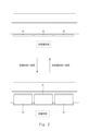
- FIG. 3 is a second diagram illustrating the protective state and non-protective state of the protective body 40.
- the protective body 40 is configured using a wall that can be opened and closed.
- the protective body 40 in the non-protective state is in an open state.
- the protective body 40 in the protected state is in a closed state.
- the protective body 40 can be changed to the protected state by closing the protective body 40.
- the protective body 40 can be changed to the non-protective state by opening the protective body 40.
- the protective body 40 may be configured using something other than a wall.
- the protective body 40 may be configured using a fence, a pole, a cushion, or the like.
- the protective body control device 2000 operates, for example, as follows.
- the protective body control device 2000 acquires the captured image 12 generated by the camera 10. Furthermore, the protective body control device 2000 uses the captured image 12 to predict whether the vehicle 20 will come into contact with the person 30.
- the protective body control device 2000 controls the state of the protective body 40 based on the result of the prediction.
- the protective body 40 under normal circumstances may be in a non-protected state or a protected state. If the protective body 40 is in a non-protected state under normal circumstances, the protective body control device 2000 changes the state of the protective body 40 to a protected state when it predicts that the vehicle 20 will come into contact with the person 30. Since the state of the protective body 40 is automatically controlled by the protective body control device 2000, it is possible to more reliably prevent the vehicle 20 from coming into contact with the person 30, compared to a case in which the state of the protective body 40 must be manually controlled.
- the protective body 40 when it is predicted that the vehicle 20 will come into contact with the person 30, the protective body 40 can be used to prevent contact between the vehicle 20 and the person 30. Therefore, unlike the case where a warning is only given to the vehicle 20, even if the vehicle 20 is unable to avoid contact with the person 30 even after a warning is given to the vehicle 20, the protective body 40 can prevent contact between the vehicle 20 and the person 30. Therefore, it is possible to more reliably prevent the vehicle 20 from coming into contact with the person 30.
- the protective body 40 When the protective body 40 is in a protective state under normal circumstances, for example, if the protective body 40 is installed in a place where the vehicle 20 must pass when entering a parking lot of a house or store, the vehicle 20 cannot enter the parking lot.
- the protection body control device 2000 predicts whether the vehicle 20 will come into contact with the protection body 40. If it is predicted that the vehicle 20 will come into contact with the protection body 40, the protection body control device 2000 further predicts whether the vehicle 20 will come into contact with the person 30. If it is predicted that the vehicle 20 will not come into contact with the person 30, the protection body control device 2000 changes the protection body 40 to a non-protected state. In this way, it is possible to prevent contact between the vehicle 20 and the person 30, while allowing the vehicle 20 to pass through the area where the protection body 40 is installed, if necessary.
- the protective body control device 2000 of this embodiment will be described in more detail below.
- ⁇ Example of functional configuration> 4 is a block diagram illustrating a functional configuration of the protective body control device 2000 of embodiment 1.
- the protective body control device 2000 has a prediction unit 2020 and a control unit 2040.
- the prediction unit 2020 acquires a captured image 12, and uses the captured image 12 to determine whether or not the vehicle 20 will come into contact with the person 30.
- the control unit 2040 controls the state of the protective body 40 based on the result of the prediction by the prediction unit 2020.
- Each functional component of the protective body control device 2000 may be realized by hardware that realizes each functional component (e.g., a hardwired electronic circuit, etc.), or may be realized by a combination of hardware and software (e.g., a combination of an electronic circuit and a program that controls it, etc.)
- a further explanation will be given of the case where each functional component of the protective body control device 2000 is realized by a combination of hardware and software.
- FIG. 5 is a block diagram illustrating an example of the hardware configuration of a computer 1000 that realizes the protective body control device 2000.
- the computer 1000 is any computer.
- the computer 1000 is a stationary computer such as a PC (Personal Computer) or a server machine.
- the computer 1000 is a portable computer such as a smartphone or a tablet terminal.
- the computer 1000 may be a dedicated computer designed to realize the protective body control device 2000, or may be a general-purpose computer.
- each function of the protective body control device 2000 is realized on the computer 1000.
- the above application is composed of a program for realizing each functional component of the protective body control device 2000.
- the above program may be acquired by any method.
- the program may be acquired from a storage medium (such as a DVD disk or USB memory) on which the program is stored.
- the program may be acquired by downloading the program from a server device that manages the storage device on which the program is stored.
- Computer 1000 has bus 1020, processor 1040, memory 1060, storage device 1080, input/output interface 1100, and network interface 1120.
- Bus 1020 is a data transmission path for processor 1040, memory 1060, storage device 1080, input/output interface 1100, and network interface 1120 to transmit and receive data to and from each other.
- the method of connecting processor 1040 and the like to each other is not limited to bus connection.
- the processor 1040 is a variety of processors, such as a CPU (Central Processing Unit), a GPU (Graphics Processing Unit), or an FPGA (Field-Programmable Gate Array).
- the memory 1060 is a primary storage device realized using RAM (Random Access Memory) or the like.
- the storage device 1080 is an auxiliary storage device realized using a hard disk, SSD (Solid State Drive), memory card, ROM (Read Only Memory), or the like.
- the input/output interface 1100 is an interface for connecting the computer 1000 to an input/output device.
- an input device such as a keyboard and an output device such as a display device are connected to the input/output interface 1100.
- the network interface 1120 is an interface for connecting the computer 1000 to a network.
- This network may be a LAN (Local Area Network) or a WAN (Wide Area Network).
- the storage device 1080 stores a program that realizes each functional component of the protective body control device 2000 (a program that realizes the application described above).
- the processor 1040 reads this program into the memory 1060 and executes it to realize each functional component of the protective body control device 2000.
- the protective body control device 2000 may be realized by one computer 1000, or may be realized by multiple computers 1000. In the latter case, the configuration of each computer 1000 does not need to be the same, and can be different from each other.
- the protection body control device 2000 is provided near the location to be monitored.
- the protection body control device 2000 is realized by an edge device provided on a street light on the side of the road.
- the protection body control device 2000 may be built into the camera 10.
- the protection body control device 2000 does not necessarily need to be provided near the location to be monitored, and may be provided in a data center, etc.
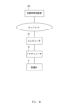
- Fig. 6 is a block diagram illustrating the configuration of the protective body 40.
- the protective body 40 is connected to an actuator 100.
- the actuator 100 physically changes the state of the protective body 40. For example, if the protective body 40 is a wall that can be raised and lowered, the actuator 100 raises and lowers the protective body 40.
- the actuator 100 is connected to a computer 200.
- the computer 200 is realized, for example, by a semiconductor chip (e.g., a System on Chip (SoC)).
- SoC System on Chip
- the configuration of the computer 200 is, for example, similar to that of the computer 1000.
- Computer 200 is connected to protective body control device 2000 (computer 1000) via a network.
- Computer 200 receives control information from protective body control device 2000 and controls actuator 100 according to the received control information. This causes the state of protective body 40 to change according to the control information from protective body control device 2000.
- Fig. 7 is a flow chart illustrating the flow of processing executed by the protective body control device 2000 of the first embodiment.
- the protective body control device 2000 controls the protective body 40 in the location to be monitored (the location imaged by the camera 10) by repeatedly executing the processing of Fig. 7.
- the prediction unit 2020 acquires the captured image 12 (S102).
- the prediction unit 2020 predicts whether the vehicle 20 will come into contact with the person 30 (S104).
- the control unit 2040 controls the state of the protective body 40 based on the prediction result (S106).
- the protective body control device 2000 acquires the captured image 12 (S102). There are various methods for acquiring the captured image generated by the camera.
- the camera 10 is configured to transmit the generated captured image 12 to the protective body control device 2000.
- the protective body control device 2000 acquires the captured image 12 by receiving the captured image 12 transmitted by the camera 10.
- the camera 10 stores the generated captured image 12 in a memory unit accessible from the protective body control device 2000.
- the protective body control device 2000 obtains the captured image 12 by accessing this memory unit.
- multiple cameras 10 may be provided.
- the protective body control device 2000 acquires the captured images 12 generated by each of the multiple cameras 10.
- the prediction unit 2020 uses the captured image 12 to predict whether the vehicle 20 will come into contact with the person 30 (S104). For example, the prediction unit 2020 executes a process for detecting the vehicle 20 and a process for detecting the person 30 on the captured image 12. Here, various existing processes can be used for the process for detecting a predetermined type of object from the captured image. Note that, when a plurality of cameras 10 are installed at a location to be monitored, the prediction unit 2020 detects the vehicle 20 and the person 30 using the captured images 12 obtained from each of the plurality of cameras 10.
- the prediction unit 2020 predicts that the vehicle 20 will not come into contact with the person 30. On the other hand, if one or more vehicles 20 and people 30 are detected in the captured image 12, the prediction unit 2020 predicts whether or not the vehicle 20 will come into contact with the person 30 for each pair of vehicles 20 and people 30, using the time series data of the captured images 12 acquired so far (for example, using the time series data of the captured images 12 generated within a predetermined time in the past).
- the prediction unit 2020 identifies the position, speed, acceleration, and direction of movement for each vehicle 20 and each person 30 by analyzing the time series data of the captured images 12.
- the prediction unit 2020 predicts changes in the position of each vehicle 20 and each person 30 based on the position, speed, acceleration, and direction of movement.
- the prediction unit 2020 determines whether or not the distance between the predicted position of the vehicle 20 and the predicted position of the person 30 is sufficiently small (for example, equal to or less than a predetermined threshold).
- the prediction unit 2020 predicts that the vehicle 20 and the person 30 will come into contact. On the other hand, if the distance between the predicted position of the vehicle 20 and the predicted position of the person 30 does not become sufficiently small (e.g., does not become equal to or below a predetermined threshold), the prediction unit 2020 predicts that the vehicle 20 and the person 30 will not come into contact.
- the prediction unit 2020 may use the captured image 12 to identify auxiliary information such as the status of traffic lights, the status of the turn signals of the vehicle 20, or the status of the brake lights of the vehicle 20, and use this auxiliary information to predict whether or not the vehicle 20 and the person 30 will come into contact.
- auxiliary information such as the status of traffic lights, the status of the turn signals of the vehicle 20, or the status of the brake lights of the vehicle 20, and use this auxiliary information to predict whether or not the vehicle 20 and the person 30 will come into contact.
- control of protective body 40 by the control unit 2040 will be given for both a case in which the protective body 40 is in a non-protected state under normal circumstances and a case in which the protective body 40 is in a protected state under normal circumstances.
- the protection body control device 2000 changes the state of the protection body 40 capable of preventing contact between the vehicle 20 and the person 30 to a protection state.
- the control unit 2040 selects, from among the multiple protection bodies 40, a protection body 40 capable of preventing contact between the vehicle 20 and the person 30 as a protection body 40 to be controlled. Then, the control unit 2040 changes the state of the protection body 40 selected as the control object to a protection state.
- control unit 2040 transmits control information to the protection body 40 selected as the control object, instructing the state of the protection body 40 to be changed to the protection state.
- transmitting control information to the protection body 40 means, for example, transmitting control information to the computer 200 described in FIG. 6.
- the protective bodies 40 that can prevent contact between the vehicle 20 and the person 30 are identified, for example, based on the position of the vehicle 20, the position of the person 30, and the position of each protective body 40.
- the control unit 2040 selects the protective bodies 40 that exist on the line connecting the position of the vehicle 20 and the position of the person 30 as the protective bodies 40 to be controlled.
- the control unit 2040 selects the protective bodies 40 whose distance from the line connecting the position of the vehicle 20 and the position of the person 30 is equal to or less than a predetermined threshold as the protective bodies 40 to be controlled.
- the control unit 2040 may also select the protective bodies 40 located in the vicinity (e.g., adjacent) of the protective body 40 selected as the control object by the above-mentioned method as the control object.
- the protection body control device 2000 may monitor contact between the vehicle 20 and the person 30 at each of a number of monitoring locations.
- the protection body 40 to be controlled at each monitoring location may be predefined in association with each monitoring location.
- the control unit 2040 predicts that the vehicle 20 will come into contact with the person 30 at a certain monitoring location, it may set all protection bodies 40 corresponding to that monitoring location to a protection state. In this way, with the method of setting all protection bodies 40 related to a monitoring location as control objects, the protection bodies 40 to be controlled can be easily selected, and the state of the protection bodies 40 can be changed to a protection state in a shorter time.
- the control unit 2040 may select as the control target only those protective bodies 40 that can be changed to a protected state before the vehicle 20 comes into contact with the person 30, among the protective bodies 40 that can prevent contact between the vehicle 20 and the person 30. Whether or not the protective body 40 can be changed to a protected state before the vehicle 20 comes into contact with the person 30 can be determined based on the time required to change the protective body 40 to the protected state and the time that the vehicle 20 and the person 30 are predicted to come into contact.
- control unit 2040 selects only those protective bodies 40 that are not malfunctioning as targets for control among the protective bodies 40 that can prevent contact between the vehicle 20 and the person 30.
- the control unit 2040 may also exclude from the control targets those protective bodies 40 that can prevent contact between the vehicle 20 and the person 30 and that are predicted to come into contact with the person 30 in the process of changing to a protective state. For example, if the protective body 40 is configured to be able to rise and fall, and the person 30 is on the protective body 40 housed on the ground. In this case, if the protective body 40 is raised, there is a possibility that the protective body 40 will come into contact with the person 30. Therefore, the control unit 2040 excludes from the control targets the protective body 40 that is provided under the feet of the person 30 (in other words, does not select it as a control target).
- the protective body 40 is configured to be able to open and close, and the person 30 is on the path of movement of the protective body 40, there is a possibility that the person 30 will be pinched by the protective body 40. Therefore, such a protective body 40 is excluded from the control targets.
- the protection body control device 2000 may transmit to the vehicle 20 avoidance information requesting control to avoid contact with the person 30.
- the vehicle 20 has a function to control the running of the vehicle without the driver's operation (for example, to automatically apply the brakes to decelerate the vehicle 20).
- the vehicle 20 also has a function to receive avoidance information from the protection body control device 2000.
- the vehicle 20 performs processing to control the traveling of the vehicle in response to receiving the avoidance information from the protection body control device 2000.
- the vehicle 20 may decelerate until it stops, or change its direction of travel to a direction in which it can avoid contact with the person 30.
- the avoidance information may indicate the position of the person 30 so that the vehicle 20 can determine the direction in which it can avoid contact with the person 30.
- the avoidance information may indicate the position of each person 30 around the vehicle 20.
- the protective body control device 2000 may transmit warning information to the driver of the vehicle 20 to inform him of the danger when it is predicted that the vehicle 20 will come into contact with the person 30.
- the vehicle 20 has a function to receive warning information from the protective body control device 2000 and a function to present the received warning information to the driver.
- the process of presenting the warning information is, for example, a process of displaying a screen showing the contents of the warning information on an arbitrary display device, or a process of outputting a sound showing the contents of the warning information from a speaker.
- the display device that displays the warning information is, for example, a display device of a car navigation system, a head-up display, or a display device of the driver's mobile terminal.
- the content of the warning information can be anything that can notify the driver of the vehicle 20 of a danger.
- the content of the warning information can be a message such as "There is a person ahead" or "Please apply the brakes.”
- the protection device control device 2000 may be configured to transmit only either the avoidance information or the warning information to the vehicle 20, or may be configured to transmit both the avoidance information and the warning information.
- the prediction unit 2020 may predict again whether the vehicle 20 will come into contact with the person 30 after the avoidance information or warning information is transmitted to the vehicle 20. If it is predicted that the vehicle 20 will come into contact with the person 30, the protection body 40 is changed to the protection state. On the other hand, if it is predicted that the vehicle 20 will not come into contact with the person 30, the protection body 40 is not changed to the protection state.
- the state of the protective body 40 will not be changed. Therefore, it is possible to reduce the frequency with which the state of the protective body 40 is changed. As a result, for example, it is possible to reduce the frequency with which the protective body 40 breaks down.
- FIG. 8 is a flowchart illustrating the flow of processing executed by the protective body control device 2000 in a case where control information or warning information is used.
- the prediction unit 2020 acquires the captured image 12 (S202).
- the prediction unit 2020 uses the captured image 12 to predict whether the vehicle 20 will come into contact with the person 30 (S204).
- the protective body control device 2000 ends the processing of FIG. 8. If it is predicted that the vehicle 20 will not come into contact with the person 30 (S204: NO), the protective body control device 2000 ends the processing of FIG. 8. If it is predicted that the vehicle 20 will come into contact with the person 30 (S204: YES), the control unit 2040 transmits warning information or avoidance information to the vehicle 20 (S206).
- the prediction unit 2020 acquires the captured image 12 generated after execution of S204 (S208). The prediction unit 2020 further uses the captured image 12 acquired in S208 to predict whether or not the vehicle 20 will come into contact with the person 30 (S210).
- the control unit 2040 changes the state of the protective body 40 to a protective state (S212). On the other hand, if it is predicted that the vehicle 20 will not come into contact with the person 30 (S210: NO), the protective body control device 2000 ends the processing of FIG. 8.
- the vehicle 20 that has received the avoidance information from the protection body control device 2000 may transmit response information representing information related to the automatic control of the vehicle 20 to the protection body control device 2000.
- the response information includes, for example, information such as the predicted stopping position of the vehicle 20 and the braking distance of the vehicle 20.
- the prediction unit 2020 may use the information on the predicted stopping position and braking distance indicated in the response information when predicting whether or not the vehicle 20 and the person 30 will come into contact after the avoidance information is transmitted.
- the prediction unit 2020 predicts that the vehicle 20 will not come into contact with the person 30.
- the prediction unit 2020 predicts that the vehicle 20 will come into contact with the person 30.
- the protection body control device 2000 changes the protection body 40 to a non-protected state when it is predicted that the vehicle 20 will come into contact with the protection body 40, but is also predicted that the vehicle 20 will not come into contact with the person 30. In this way, for example, in a case where the boundary between the roadway and the sidewalk is normally blocked by the protection body 40, it is possible for the vehicle 20 to pass through the sidewalk and enter a parking lot.
- the prediction unit 2020 predicts whether or not the vehicle 20 will come into contact with the protective body 40. For example, the prediction unit 2020 predicts the movement path of the vehicle 20 by identifying the position and movement direction of the vehicle 20 using the time series data of the captured image 12. Then, if the protective body 40 is present on the movement path of the vehicle 20, the prediction unit 2020 predicts that the vehicle 20 will come into contact with the protective body 40. On the other hand, if the protective body 40 is not present on the movement path of the vehicle 20, the prediction unit 2020 predicts that the vehicle 20 will not come into contact with the protective body 40.
- the prediction unit 2020 predicts whether or not the vehicle 20 will come into contact with the person 30 if the protective body 40 is put into a non-protected state (for example, if it is assumed that the protective body 40 does not exist).
- the method of predicting whether or not the vehicle 20 and the person 30 will come into contact is as described above.
- the prediction unit 2020 does not change the protective body 40 to a non-protected state. On the other hand, if it is predicted that the vehicle 20 will not come into contact with the person 30, the prediction unit 2020 changes the protective body 40 to a non-protected state.
- the prediction unit 2020 After changing the protective body 40 to the non-protected state, it is preferable for the prediction unit 2020 to change the protective body 40 back to the protected state at a timing when there is no vehicle 20 in contact with the protective body 40. In this way, the time during which the protective body 40 is in the non-protected state can be kept to the minimum necessary.
- the protection body control device 2000 may perform an operation test of the protection body 40 during a period when the probability of the vehicle 20 coming into contact with the person 30 is low.
- the period when the probability of the vehicle 20 coming into contact with the person 30 is low is, for example, a time period when traffic volume (i.e., the number of vehicles 20 traveling on the road) is low in the monitored location.
- the time period when traffic volume is low in the monitored location is, for example, manually set by an administrator of the protection body control device 2000.
- the time period when traffic volume is low in the monitored location may be identified by the protection body control device 2000 based on the result of detecting the vehicle 20 from the captured image 12.
- the protective body control device 2000 detects the vehicle 20 from the time series data of the captured image 12. While the vehicle 20 is detected in the captured image 12, the protective body control device 2000 does not perform an operation test of the protective body 40. On the other hand, when the vehicle 20 is no longer detected in the captured image 12, the protective body control device 2000 performs an operation test of the protective body 40. Note that the operation test of the protective body 40 may be performed immediately when the vehicle 20 is no longer detected in the captured image 12, or the operation test of the protective body 40 may be performed when the situation where the vehicle 20 is not detected in the captured image 12 continues for a certain period of time (for example, when it continues for a predetermined length of time or more).
- the operation test of the protective body 40 may include various tests.
- the protective body control device 2000 measures the time from when a control signal for changing the state is sent to the protective body 40 to when the state change of the protective body 40 is completed (i.e., the time required for the state change) for each protective body 40, and stores this in the memory unit.
- the required time is measured for both the time required to change from a protected state to a non-protected state and the time required to change from a non-protected state to a protected state.
- the time when the change in state of the protective body 40 is completed may be determined using the captured image 12, or may be determined using a completion notification transmitted from the protective body 40 to the protective body control device 2000.
- the completion notification is a notification transmitted from the protective body 40 to the protective body control device 2000 in response to the completion of the change in state of the protective body 40.
- the protective body control device 2000 determines that the protective body 40 is broken.
- the protective body control device 2000 stores the identification information of the broken protective body 40 in the memory unit. In this way, it is possible to exclude the broken protective body 40 from being subject to control by the control unit 2040, and to identify protective bodies 40 that need repair.
- the program includes instructions (or software code) that, when loaded into a computer, cause the computer to perform one or more functions described in the embodiments.
- the program may be stored on a non-transitory computer-readable medium or a tangible storage medium.
- computer-readable medium or tangible storage medium may include random-access memory (RAM), read-only memory (ROM), flash memory, solid-state drive (SSD) or other memory technology, CD-ROM, digital versatile disc (DVD), Blu-ray (registered trademark) disc or other optical disk storage, magnetic cassette, magnetic tape, magnetic disk storage or other magnetic storage device.
- the program may be transmitted on a transitory computer-readable medium or a communication medium.
- the transitory computer-readable medium or communication medium may include electrical, optical, acoustic, or other forms of propagated signals.
- a part or all of the above-described embodiments can be described as, but is not limited to, the following supplementary notes.
- Appendix 1 A prediction means for predicting whether or not a vehicle will come into contact with a person;
- a protection body control device having a control means for controlling the state of the protection body, which can be a protected state that hinders the progress of the vehicle, and a non-protected state that does not hinder the progress of the vehicle, based on the results of prediction by the prediction means.
- Appendix 2 The protection body control device described in Appendix 1, wherein the control means, when it is predicted that the vehicle will come into contact with a person, identifies from among a plurality of protection bodies a protection body that can hinder the vehicle's progress based on the position of the vehicle, the person, or both, and changes the state of the identified protection body to the protection state.
- the control means When it is predicted that the vehicle will come into contact with a person, transmitting to the vehicle avoidance information requesting control for avoiding contact with the person, warning information notifying the vehicle of a danger, or both of these; the prediction means predicts whether or not the vehicle will come into contact with a person after the avoidance information or the warning information is transmitted;
- the protection body control device described in Appendix 1 or 2 wherein the control means changes the state of the protection body to the protection state when it is predicted that the vehicle will come into contact with a person after the avoidance information or the warning information is transmitted.
- the control means For each of the protective bodies, a required time required for the protective body to change from the non-protected state to the protected state is stored in a storage unit, The control means identifies, from among the multiple protective bodies, a protective body that can hinder the progress of a vehicle predicted to come into contact with a person based on the required time for each protective body, and changes the state of the identified protective body to the protective state.
- the prediction means includes: predicting whether a vehicle will come into contact with the guard; predicting whether the vehicle will come into contact with a person when it is predicted that the vehicle will come into contact with the protective body; A protection body control device as described in Appendix 1, which changes the state of the protection body predicted to come into contact with the vehicle to the non-protection state when it is predicted that the vehicle will not come into contact with a person.
- Appendix 6 The protection device according to claim 1, 2, or 5, wherein the protection device is provided between a road and a sidewalk.
- (Appendix 7) a prediction step of predicting whether the vehicle will come into contact with a person;
- a protection control method executed by a computer comprising: a control step of controlling the state of the protection, which can be a protected state that hinders the progress of the vehicle, and a non-protected state that does not hinder the progress of the vehicle, based on the result of prediction by the prediction step.
- (Appendix 8) A protective body control method as described in Appendix 7, in which, in the control step, when it is predicted that the vehicle will come into contact with a person, a protective body that can hinder the progress of the vehicle is identified from among a plurality of protective bodies based on the position of the vehicle, the person, or both, and the state of the identified protective body is changed to the protective state.
- a non-transitory computer-readable medium storing a program for causing a computer to execute the steps of: a control step for controlling the state of a protective body, which can be a protected state that hinders the progress of the vehicle, and a non-protected state that does not hinder the progress of the vehicle, based on the results of prediction by the prediction step.
- Appendix 14 The readable medium of Appendix 13, wherein in the control step, when it is predicted that the vehicle will come into contact with a person, a protective body that can hinder the progress of the vehicle is identified from among a plurality of protective bodies based on the position of the vehicle, the person, or both, and the state of the identified protective body is changed to the protective state.
- a required time required for the protective body to change from the non-protected state to the protected state is stored in a storage unit, A readable medium as described in Appendix 13 or 14, in which, in the control step, a protective body that can hinder the progress of a vehicle predicted to come into contact with a person is identified from among the multiple protective bodies based on the required time for each protective body, and the state of the identified protective body is changed to the protective state.
Landscapes
- Physics & Mathematics (AREA)
- General Physics & Mathematics (AREA)
- Traffic Control Systems (AREA)
Abstract
Description
<概要>
図1は、実施形態1の防護体制御装置2000の動作の概要を例示する図である。ここで、図1は、防護体制御装置2000の概要の理解を容易にするための図であり、防護体制御装置2000の動作は、図1に示したものに限定されない。
図4は、実施形態1の防護体制御装置2000の機能構成を例示するブロック図である。防護体制御装置2000は、予測部2020及び制御部2040を有する。予測部2020は、撮像画像12を取得し、撮像画像12を用いて、車両20が人30に接触するか否かを判定する。制御部2040は、予測部2020による予測の結果に基づいて、防護体40の状態を制御する。
防護体制御装置2000の各機能構成部は、各機能構成部を実現するハードウエア(例:ハードワイヤードされた電子回路など)で実現されてもよいし、ハードウエアとソフトウエアとの組み合わせ(例:電子回路とそれを制御するプログラムの組み合わせなど)で実現されてもよい。以下、防護体制御装置2000の各機能構成部がハードウエアとソフトウエアとの組み合わせで実現される場合について、さらに説明する。
図6は、防護体40の構成を例示するブロック図である。図6において、防護体40はアクチュエータ100と接続されている。アクチュエータ100は、防護体40の状態を物理的に変更させる。例えば防護体40が昇降可能な壁である場合、アクチュエータ100は防護体40の昇降を行う。
図7は、実施形態1の防護体制御装置2000によって実行される処理の流れを例示するフローチャートである。防護体制御装置2000は、図7の処理を繰り返し実行することにより、監視対象の場所(カメラ10によって撮像されている場所)における防護体40の制御を行う。予測部2020は撮像画像12を取得する(S102)。予測部2020は、車両20が人30に接触するか否かを予測する(S104)。制御部2040は、予測結果に基づいて、防護体40の状態を制御する(S106)。
防護体制御装置2000は、撮像画像12を取得する(S102)。ここで、カメラによって生成される撮像画像を取得する方法は様々である。例えばカメラ10は、生成した撮像画像12を防護体制御装置2000へ送信するように構成される。この場合、防護体制御装置2000は、カメラ10によって送信された撮像画像12を受信することで、撮像画像12を取得する。
予測部2020は、撮像画像12を用いて、車両20が人30と接触するか否かを予測する(S104)。例えば予測部2020は、撮像画像12に対して、車両20を検出する処理、及び人30を検出する処理をそれぞれ実行する。ここで、撮像画像から所定の種類の物体を検出する処理には、既存の種々の処理を利用できる。なお、監視対象の場所にカメラ10が複数設けられている場合、予測部2020は、これら複数のカメラ10それぞれから得られる撮像画像12を用いて、車両20と人30の検出を行う。
以下、通常時の防護体40が非防護状態であるケースと、通常時の防護体40が防護状態であるケースのそれぞれについて、制御部2040による防護体40の制御を例示する。
このケースにおいて、防護体制御装置2000は、車両20が人30に接触すると予測される場合に、その車両20とその人30との接触を防ぐことができる防護体40の状態を、防護状態に変更する。そこで例えば、制御部2040は、複数の防護体40の中から、車両20と人30との接触を防ぐことができる防護体40を、制御対象の防護体40として選択する。そして、制御部2040は、制御対象として選択された防護体40の状態を、防護状態に変更する。具体的には、制御部2040は、制御対象として選択された防護体40に対して、防護体40の状態を防護状態に変更することを指示する制御情報を送信する。ここで、防護体40に対して制御情報を送信することは、例えば、図6で説明したコンピュータ200に対して制御情報を送信することを意味する。
防護体制御装置2000は、車両20が人30に接触すると予測された場合に、車両20に対し、人30との接触を回避するための制御を要求する回避情報を送信してもよい。この場合、例えば車両20は、運転手の操作によらずに自車の走行を制御する(例えば、自動的にブレーキを動作させて車両20を減速させる)機能を有する。また、車両20は、防護体制御装置2000からの回避情報を受信する機能を有する。
このケースにおいて、防護体制御装置2000は、車両20が防護体40に接触すると予測され、なおかつ、車両20が人30に接触しないと予測される場合に、その防護体40を非防護状態に変更する。こうすることで、例えば、通常時には車道と歩道との境界が防護体40によって塞がれているケースにおいて、車両20が歩道を通過して駐車場に入るといったことを可能にする。
防護体制御装置2000は、車両20が人30に接触する蓋然性が低い期間において、防護体40の動作テストを行ってもよい。車両20が人30に接触する蓋然性が低い期間は、例えば、監視対象の場所において交通量(すなわち、道路を走る車両20の数)が少ない時間帯である。監視対象の場所において交通量が少ない時間帯は、例えば、防護体制御装置2000の管理者によって手動で設定される。その他にも例えば、監視対象の場所において交通量が少ない時間帯は、撮像画像12から車両20を検出した結果に基づき、防護体制御装置2000によって特定されてもよい。
(付記1)
車両が人に接触するか否かを予測する予測手段と、
前記車両の進行を妨げる状態である防護状態と、前記車両の進行を妨げない状態である非防護状態とをとりうる防護体の状態を、前記予測手段による予測の結果に基づいて制御する制御手段と、を有する防護体制御装置。
(付記2)
前記制御手段は、車両が人に接触すると予測された場合に、前記車両、前記人、又はそれら双方の位置に基づいて、複数の前記防護体の中から、前記車両の進行を妨げることができる前記防護体を特定し、前記特定した防護体の状態を前記防護状態に変更する、付記1に記載の防護体制御装置。
(付記3)
前記制御手段は、
車両が人に接触すると予測された場合に、前記車両に対して、人との接触を回避するための制御を要求する回避情報、危険を知らせる警告情報、又はこれらの双方を送信し、
前記予測手段は、前記回避情報又は前記警告情報が送信された後に、前記車両が人に接触するか否かを予測し、
前記制御手段は、前記回避情報又は前記警告情報が送信された後に、前記車両が人に接触すると予測された場合、前記防護体の状態を前記防護状態に変更する、付記1又は2に記載の防護体制御装置。
(付記4)
各前記防護体について、前記非防護状態から前記防護状態となるまでに要する所要時間が記憶部に格納されており、
前記制御手段は、各前記防護体の前記所要時間に基づいて、複数の前記防護体の中から、人に接触すると予測された車両の進行を妨げることができる前記防護体を特定し、前記特定した防護体の状態を前記防護状態に変更する、付記1又は2に記載の防護体制御装置。
(付記5)
前記予測手段は、
車両が前記防護体に接触するか否かを予測し、
車両が前記防護体に接触すると予測された場合に、前記車両が人に接触するか否かを予測し、
前記車両が人に接触しないと予測された場合に、前記車両に接触すると予測された前記防護体の状態を、前記非防護状態に変更する、付記1に記載の防護体制御装置。
(付記6)
前記防護体は、道路と歩道との間に設けられている、付記1、2、又は5に記載の防護体制御装置。
(付記7)
車両が人に接触するか否かを予測する予測ステップと、
前記車両の進行を妨げる状態である防護状態と、前記車両の進行を妨げない状態である非防護状態とをとりうる防護体の状態を、前記予測ステップによる予測の結果に基づいて制御する制御ステップと、を有する、コンピュータによって実行される防護体制御方法。
(付記8)
前記制御ステップにおいて、車両が人に接触すると予測された場合に、前記車両、前記人、又はそれら双方の位置に基づいて、複数の前記防護体の中から、前記車両の進行を妨げることができる前記防護体を特定し、前記特定した防護体の状態を前記防護状態に変更する、付記7に記載の防護体制御方法。
(付記9)
前記制御ステップにおいて、
車両が人に接触すると予測された場合に、前記車両に対して、人との接触を回避するための制御を要求する回避情報、危険を知らせる警告情報、又はこれらの双方を送信し、
前記予測ステップにおいて、前記回避情報又は前記警告情報が送信された後に、前記車両が人に接触するか否かを予測し、
前記制御ステップにおいて、前記回避情報又は前記警告情報が送信された後に、前記車両が人に接触すると予測された場合、前記防護体の状態を前記防護状態に変更する、付記7又は8に記載の防護体制御方法。
(付記10)
各前記防護体について、前記非防護状態から前記防護状態となるまでに要する所要時間が記憶部に格納されており、
前記制御ステップにおいて、各前記防護体の前記所要時間に基づいて、複数の前記防護体の中から、人に接触すると予測された車両の進行を妨げることができる前記防護体を特定し、前記特定した防護体の状態を前記防護状態に変更する、付記7又は8に記載の防護体制御方法。
(付記11)
前記予測ステップにおいて、
車両が前記防護体に接触するか否かを予測し、
車両が前記防護体に接触すると予測された場合に、前記車両が人に接触するか否かを予測し、
前記車両が人に接触しないと予測された場合に、前記車両に接触すると予測された前記防護体の状態を、前記非防護状態に変更する、付記7に記載の防護体制御方法。
(付記12)
前記防護体は、道路と歩道との間に設けられている、付記7、8、又は11に記載の防護体制御方法。
(付記13)
車両が人に接触するか否かを予測する予測ステップと、
前記車両の進行を妨げる状態である防護状態と、前記車両の進行を妨げない状態である非防護状態とをとりうる防護体の状態を、前記予測ステップによる予測の結果に基づいて制御する制御ステップと、をコンピュータに実行させるプログラムが格納されている非一時的なコンピュータ可読媒体。
(付記14)
前記制御ステップにおいて、車両が人に接触すると予測された場合に、前記車両、前記人、又はそれら双方の位置に基づいて、複数の前記防護体の中から、前記車両の進行を妨げることができる前記防護体を特定し、前記特定した防護体の状態を前記防護状態に変更する、付記13に記載の可読媒体。
(付記15)
前記制御ステップにおいて、
車両が人に接触すると予測された場合に、前記車両に対して、人との接触を回避するための制御を要求する回避情報、危険を知らせる警告情報、又はこれらの双方を送信し、
前記予測ステップにおいて、前記回避情報又は前記警告情報が送信された後に、前記車両が人に接触するか否かを予測し、
前記制御ステップにおいて、前記回避情報又は前記警告情報が送信された後に、前記車両が人に接触すると予測された場合、前記防護体の状態を前記防護状態に変更する、付記13又は14に記載の可読媒体。
(付記16)
各前記防護体について、前記非防護状態から前記防護状態となるまでに要する所要時間が記憶部に格納されており、
前記制御ステップにおいて、各前記防護体の前記所要時間に基づいて、複数の前記防護体の中から、人に接触すると予測された車両の進行を妨げることができる前記防護体を特定し、前記特定した防護体の状態を前記防護状態に変更する、付記13又は14に記載の可読媒体。
(付記17)
前記予測ステップにおいて、
車両が前記防護体に接触するか否かを予測し、
車両が前記防護体に接触すると予測された場合に、前記車両が人に接触するか否かを予測し、
前記車両が人に接触しないと予測された場合に、前記車両に接触すると予測された前記防護体の状態を、前記非防護状態に変更する、付記13に記載の可読媒体。
(付記18)
前記防護体は、道路と歩道との間に設けられている、付記13、14、又は17に記載の可読媒体。
12 撮像画像
20 車両
30 人
40 防護体
100 アクチュエータ
200 コンピュータ
1000 コンピュータ
1020 バス
1040 プロセッサ
1060 メモリ
1080 ストレージデバイス
1100 入出力インタフェース
1120 ネットワークインタフェース
2000 防護体制御装置
2020 予測部
2040 制御部
Claims (18)
- 車両が人に接触するか否かを予測する予測手段と、
前記車両の進行を妨げる状態である防護状態と、前記車両の進行を妨げない状態である非防護状態とをとりうる防護体の状態を、前記予測手段による予測の結果に基づいて制御する制御手段と、を有する防護体制御装置。 - 前記制御手段は、車両が人に接触すると予測された場合に、前記車両、前記人、又はそれら双方の位置に基づいて、複数の前記防護体の中から、前記車両の進行を妨げることができる前記防護体を特定し、前記特定した防護体の状態を前記防護状態に変更する、請求項1に記載の防護体制御装置。
- 前記制御手段は、
車両が人に接触すると予測された場合に、前記車両に対して、人との接触を回避するための制御を要求する回避情報、危険を知らせる警告情報、又はこれらの双方を送信し、
前記予測手段は、前記回避情報又は前記警告情報が送信された後に、前記車両が人に接触するか否かを予測し、
前記制御手段は、前記回避情報又は前記警告情報が送信された後に、前記車両が人に接触すると予測された場合、前記防護体の状態を前記防護状態に変更する、請求項1又は2に記載の防護体制御装置。 - 各前記防護体について、前記非防護状態から前記防護状態となるまでに要する所要時間が記憶部に格納されており、
前記制御手段は、各前記防護体の前記所要時間に基づいて、複数の前記防護体の中から、人に接触すると予測された車両の進行を妨げることができる前記防護体を特定し、前記特定した防護体の状態を前記防護状態に変更する、請求項1又は2に記載の防護体制御装置。 - 前記予測手段は、
車両が前記防護体に接触するか否かを予測し、
車両が前記防護体に接触すると予測された場合に、前記車両が人に接触するか否かを予測し、
前記車両が人に接触しないと予測された場合に、前記車両に接触すると予測された前記防護体の状態を、前記非防護状態に変更する、請求項1に記載の防護体制御装置。 - 前記防護体は、道路と歩道との間に設けられている、請求項1、2、又は5に記載の防護体制御装置。
- 車両が人に接触するか否かを予測する予測ステップと、
前記車両の進行を妨げる状態である防護状態と、前記車両の進行を妨げない状態である非防護状態とをとりうる防護体の状態を、前記予測ステップによる予測の結果に基づいて制御する制御ステップと、を有する、コンピュータによって実行される防護体制御方法。 - 前記制御ステップにおいて、車両が人に接触すると予測された場合に、前記車両、前記人、又はそれら双方の位置に基づいて、複数の前記防護体の中から、前記車両の進行を妨げることができる前記防護体を特定し、前記特定した防護体の状態を前記防護状態に変更する、請求項7に記載の防護体制御方法。
- 前記制御ステップにおいて、
車両が人に接触すると予測された場合に、前記車両に対して、人との接触を回避するための制御を要求する回避情報、危険を知らせる警告情報、又はこれらの双方を送信し、
前記予測ステップにおいて、前記回避情報又は前記警告情報が送信された後に、前記車両が人に接触するか否かを予測し、
前記制御ステップにおいて、前記回避情報又は前記警告情報が送信された後に、前記車両が人に接触すると予測された場合、前記防護体の状態を前記防護状態に変更する、請求項7又は8に記載の防護体制御方法。 - 各前記防護体について、前記非防護状態から前記防護状態となるまでに要する所要時間が記憶部に格納されており、
前記制御ステップにおいて、各前記防護体の前記所要時間に基づいて、複数の前記防護体の中から、人に接触すると予測された車両の進行を妨げることができる前記防護体を特定し、前記特定した防護体の状態を前記防護状態に変更する、請求項7又は8に記載の防護体制御方法。 - 前記予測ステップにおいて、
車両が前記防護体に接触するか否かを予測し、
車両が前記防護体に接触すると予測された場合に、前記車両が人に接触するか否かを予測し、
前記車両が人に接触しないと予測された場合に、前記車両に接触すると予測された前記防護体の状態を、前記非防護状態に変更する、請求項7に記載の防護体制御方法。 - 前記防護体は、道路と歩道との間に設けられている、請求項7、8、又は11に記載の防護体制御方法。
- 車両が人に接触するか否かを予測する予測ステップと、
前記車両の進行を妨げる状態である防護状態と、前記車両の進行を妨げない状態である非防護状態とをとりうる防護体の状態を、前記予測ステップによる予測の結果に基づいて制御する制御ステップと、をコンピュータに実行させるプログラムが格納されている非一時的なコンピュータ可読媒体。 - 前記制御ステップにおいて、車両が人に接触すると予測された場合に、前記車両、前記人、又はそれら双方の位置に基づいて、複数の前記防護体の中から、前記車両の進行を妨げることができる前記防護体を特定し、前記特定した防護体の状態を前記防護状態に変更する、請求項13に記載の可読媒体。
- 前記制御ステップにおいて、
車両が人に接触すると予測された場合に、前記車両に対して、人との接触を回避するための制御を要求する回避情報、危険を知らせる警告情報、又はこれらの双方を送信し、
前記予測ステップにおいて、前記回避情報又は前記警告情報が送信された後に、前記車両が人に接触するか否かを予測し、
前記制御ステップにおいて、前記回避情報又は前記警告情報が送信された後に、前記車両が人に接触すると予測された場合、前記防護体の状態を前記防護状態に変更する、請求項13又は14に記載の可読媒体。 - 各前記防護体について、前記非防護状態から前記防護状態となるまでに要する所要時間が記憶部に格納されており、
前記制御ステップにおいて、各前記防護体の前記所要時間に基づいて、複数の前記防護体の中から、人に接触すると予測された車両の進行を妨げることができる前記防護体を特定し、前記特定した防護体の状態を前記防護状態に変更する、請求項13又は14に記載の可読媒体。 - 前記予測ステップにおいて、
車両が前記防護体に接触するか否かを予測し、
車両が前記防護体に接触すると予測された場合に、前記車両が人に接触するか否かを予測し、
前記車両が人に接触しないと予測された場合に、前記車両に接触すると予測された前記防護体の状態を、前記非防護状態に変更する、請求項13に記載の可読媒体。 - 前記防護体は、道路と歩道との間に設けられている、請求項13、14、又は17に記載の可読媒体。
Priority Applications (2)
| Application Number | Priority Date | Filing Date | Title |
|---|---|---|---|
| PCT/JP2023/012285 WO2024201673A1 (ja) | 2023-03-27 | 2023-03-27 | 防護体制御装置、防護体制御方法、及び非一時的なコンピュータ可読媒体 |
| JP2025509299A JPWO2024201673A5 (ja) | 2023-03-27 | 防護体制御装置、防護体制御方法、及びプログラム |
Applications Claiming Priority (1)
| Application Number | Priority Date | Filing Date | Title |
|---|---|---|---|
| PCT/JP2023/012285 WO2024201673A1 (ja) | 2023-03-27 | 2023-03-27 | 防護体制御装置、防護体制御方法、及び非一時的なコンピュータ可読媒体 |
Publications (1)
| Publication Number | Publication Date |
|---|---|
| WO2024201673A1 true WO2024201673A1 (ja) | 2024-10-03 |
Family
ID=92903549
Family Applications (1)
| Application Number | Title | Priority Date | Filing Date |
|---|---|---|---|
| PCT/JP2023/012285 Ceased WO2024201673A1 (ja) | 2023-03-27 | 2023-03-27 | 防護体制御装置、防護体制御方法、及び非一時的なコンピュータ可読媒体 |
Country Status (1)
| Country | Link |
|---|---|
| WO (1) | WO2024201673A1 (ja) |
Citations (3)
| Publication number | Priority date | Publication date | Assignee | Title |
|---|---|---|---|---|
| JP2002541536A (ja) * | 1999-02-05 | 2002-12-03 | ブレット・ホール | 衝突防止システム |
| CN203295992U (zh) * | 2013-05-24 | 2013-11-20 | 刘力豪 | 一种控制人行横道上行人和车辆通行的系统 |
| WO2020066813A1 (ja) * | 2018-09-26 | 2020-04-02 | 京セラ株式会社 | 基地局、車両、所定端末及び交通通信システム |
-
2023
- 2023-03-27 WO PCT/JP2023/012285 patent/WO2024201673A1/ja not_active Ceased
Patent Citations (3)
| Publication number | Priority date | Publication date | Assignee | Title |
|---|---|---|---|---|
| JP2002541536A (ja) * | 1999-02-05 | 2002-12-03 | ブレット・ホール | 衝突防止システム |
| CN203295992U (zh) * | 2013-05-24 | 2013-11-20 | 刘力豪 | 一种控制人行横道上行人和车辆通行的系统 |
| WO2020066813A1 (ja) * | 2018-09-26 | 2020-04-02 | 京セラ株式会社 | 基地局、車両、所定端末及び交通通信システム |
Also Published As
| Publication number | Publication date |
|---|---|
| JPWO2024201673A1 (ja) | 2024-10-03 |
Similar Documents
| Publication | Publication Date | Title |
|---|---|---|
| US12459468B2 (en) | Vehicle control device and vehicle control method | |
| JP6112054B2 (ja) | 電子機器、電子機器の制御方法及び電子機器の制御プログラム | |
| JP6834805B2 (ja) | 電子制御装置 | |
| CN114348025B (zh) | 一种车辆驾驶监控系统、方法、设备及存储介质 | |
| US20190185018A1 (en) | ALARM SYSTEM OF AUTONOMOUS DRIVING VEHICLES (ADVs) | |
| US10836412B2 (en) | System, method, and program for preventing accidents | |
| KR20210138463A (ko) | 보행자 사고방지 방법 및 그 장치 | |
| US20230076404A1 (en) | Traveling state determination apparatus, cutting-in warning apparatus, method, andcomputer readable medium | |
| JP2010067235A (ja) | 運転支援装置および運転支援プログラム | |
| US10435051B1 (en) | System, method, and program for preventing accidents | |
| CN111971723A (zh) | 驾驶监视装置和驾驶监视程序 | |
| CA3056611A1 (fr) | Systeme de generation automatique d'alertes destinees aux usagers d'une route | |
| JP2011028415A (ja) | 運転支援装置 | |
| US20230133873A1 (en) | Remote monitoring system, remote monitoring apparatus, and method | |
| KR20250036787A (ko) | 최소 위험 조작을 수행하기 위한 차량 및 상기 차량의 작동 방법 | |
| WO2024201673A1 (ja) | 防護体制御装置、防護体制御方法、及び非一時的なコンピュータ可読媒体 | |
| JP2017045265A (ja) | データ記録装置およびデータ記録方法 | |
| CN113053096B (zh) | 交通事故预警方法、装置、存储介质及智能灯杆 | |
| CN118683526A (zh) | 用于驾驶员情况感知的用户界面 | |
| CN120220377A (zh) | 车辆异常行为的预警方法、装置、电子设备和存储介质 | |
| KR20240138635A (ko) | 충격 감지 센서 모듈을 이용한 차량 사고 감지 및 자동 신고용 사용자 단말기 | |
| CN116453375A (zh) | 城市道路危险数据监控管理方法、装置、电子设备及介质 | |
| JP2019172076A (ja) | 踏切情報システム | |
| CN107678427A (zh) | 一种用于控制车辆行驶的方法与设备 | |
| JP7635176B2 (ja) | 運行管理装置、運行管理装置の制御方法、及び運行管理装置の制御プログラム |
Legal Events
| Date | Code | Title | Description |
|---|---|---|---|
| 121 | Ep: the epo has been informed by wipo that ep was designated in this application |
Ref document number: 23930313 Country of ref document: EP Kind code of ref document: A1 |
|
| ENP | Entry into the national phase |
Ref document number: 2025509299 Country of ref document: JP Kind code of ref document: A |
|
| WWE | Wipo information: entry into national phase |
Ref document number: 2025509299 Country of ref document: JP |
|
| NENP | Non-entry into the national phase |
Ref country code: DE |
|
| 122 | Ep: pct application non-entry in european phase |
Ref document number: 23930313 Country of ref document: EP Kind code of ref document: A1 |