WO2024201662A1 - 物体検出装置 - Google Patents
物体検出装置 Download PDFInfo
- Publication number
- WO2024201662A1 WO2024201662A1 PCT/JP2023/012243 JP2023012243W WO2024201662A1 WO 2024201662 A1 WO2024201662 A1 WO 2024201662A1 JP 2023012243 W JP2023012243 W JP 2023012243W WO 2024201662 A1 WO2024201662 A1 WO 2024201662A1
- Authority
- WO
- WIPO (PCT)
- Prior art keywords
- image
- feature extraction
- model
- feature
- unit
- Prior art date
- Legal status (The legal status is an assumption and is not a legal conclusion. Google has not performed a legal analysis and makes no representation as to the accuracy of the status listed.)
- Ceased
Links
Images


Classifications
-
- G—PHYSICS
- G06—COMPUTING OR CALCULATING; COUNTING
- G06T—IMAGE DATA PROCESSING OR GENERATION, IN GENERAL
- G06T7/00—Image analysis
- G06T7/70—Determining position or orientation of objects or cameras
- G06T7/73—Determining position or orientation of objects or cameras using feature-based methods
-
- G—PHYSICS
- G06—COMPUTING OR CALCULATING; COUNTING
- G06T—IMAGE DATA PROCESSING OR GENERATION, IN GENERAL
- G06T2207/00—Indexing scheme for image analysis or image enhancement
- G06T2207/30—Subject of image; Context of image processing
- G06T2207/30108—Industrial image inspection
- G06T2207/30164—Workpiece; Machine component
Definitions
- This disclosure relates to an object detection device.
- a robot system that detects the position and orientation of an object based on an image captured by a visual sensor and has the robot perform a task on the object.
- detection first, image features that represent specific parts of the object, whose position and orientation is known, are extracted from the captured image by feature extraction processing and registered together with the position and orientation.
- image features that represent specific parts of the object are similarly extracted from the captured image by feature extraction processing, and the position and orientation of the object is identified based on the amount of change in the position and orientation in the image obtained by comparing it with the registered image features (model features).
- Patent documents 1 and 2 describe a device that identifies the position and orientation of an object by performing a matching process using edge points.
- the image features used for matching change depending on the feature extraction process applied. For example, even with the same edge feature extraction process, the edge features extracted by a Sobel filter and a Laplacian filter differ. Furthermore, if the imaging conditions change and the appearance of the object changes, the image features output by the feature extraction process will change. There is a demand for an object detection device that can determine a feature extraction process that can stably detect the object even in situations where the imaging conditions change.
- One aspect of the present disclosure is an object detection device that includes a feature extraction unit that extracts image features from an image, a model image receiving unit that receives a first image of an object whose position and orientation are known as a model image, a model feature storage unit that stores the first image feature extracted from the model image by the feature extraction unit as a model feature, and a detection unit that identifies the position and orientation of the object by comparing a second image feature extracted by the feature extraction unit from a second image of the object whose position and orientation are unknown with the model feature, the object detection device further including a model conversion unit that applies one or more conversion processes to the model image and the model feature to generate one or more converted model images and one or more converted model features, respectively, and a model conversion unit that converts the converted model image into a converted model image by the feature extraction unit.
- the object detection device includes a first characteristic calculation unit that calculates a first characteristic related to the characteristics of the feature extraction process by the feature extraction unit based on the extracted third image feature and the conversion model feature, and an evaluation index calculation unit that calculates an evaluation index of the feature extraction process based on one or more first characteristics calculated by the first characteristic calculation unit based on the one or more third image features and the one or more conversion model features, where the feature extraction unit has a plurality of feature extraction processes, the first characteristic calculation unit calculates the one or more first characteristics for each of the plurality of feature extraction processes based on the third image feature and the conversion model feature, and the evaluation index calculation unit calculates the evaluation index for each of the plurality of feature extraction processes to determine the feature extraction process to be applied to the detection process of the detection unit.
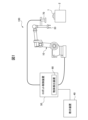
- FIG. 1 is a diagram illustrating a device configuration of a robot system including an object detection device according to an embodiment.
- FIG. 2 is a functional block diagram of a robot control device.
- FIG. 13 is a diagram showing a result of applying a Sobel filter to an image of a captured object.
- FIG. 13 is a diagram showing a result of applying a Laplacian filter to an image of a captured object.
- FIG. 11 is a data flow diagram showing the flow of data in the feature extraction process determination process.
- FIG. 11 illustrates an example of a conversion process.
- 6B is a flowchart showing the feature extraction process determination process.
- 6B is a flowchart showing the feature extraction process determination process together with FIG. 6A.
- FIG. 13 is a diagram illustrating an example of a list of evaluation indexes.
- FIG. 13 is a diagram illustrating an example of processing by a Shi-Tomasi corner detector.
- the robot system 100 includes a robot 10, a robot control device 50 that controls the robot 10, a visual sensor 70, and a teaching device 40 connected to the robot control device 50.
- the visual sensor 70 is mounted on the tip of the arm of the robot 10.
- the visual sensor 70 is connected to the robot control device 50 and operates under the control of the robot control device 50.
- the robot control device 50 is equipped with a function as an object detection device 60 that detects the position and orientation of an object 1 placed on, for example, a workbench 2 based on an image captured by the visual sensor 70.
- the robot control device 50 can cause the robot 10 to perform a predetermined task on the object 1 based on the detected position and orientation of the object 1.
- the robot 10 is a six-axis vertical articulated robot. Note that various types of robots may be used as the robot 10 depending on the work target, such as a horizontal articulated robot, a parallel link type robot, or a dual-arm robot.
- the robot 10 can perform the desired work using an end effector attached to the wrist.
- the end effector is an external device that can be replaced depending on the application, such as a hand, a welding gun, or a tool.
- Figure 1 shows an example in which a hand 33 is used as an end effector.
- the visual sensor 70 may be a camera that captures two-dimensional images such as grayscale images or color images, or a stereo camera or three-dimensional sensor that can obtain distance images or three-dimensional point clouds. In this embodiment, it is assumed that the visual sensor 70 is a camera that captures two-dimensional images.
- the robot control device 50 holds model data of the object and can execute a detection process that identifies the position and orientation of the object by matching the image of the object in the captured image with the model data (pattern matching). In this embodiment, it is assumed that the visual sensor 70 has been calibrated, and that the robot control device 50 holds calibration data that defines the relative positional relationship between the visual sensor 70 and the robot 10. This makes it possible to convert a position on an image captured by the visual sensor 70 into a position on a coordinate system (such as a robot coordinate system) fixed to the working space.
- a coordinate system such as a robot coordinate system
- the robot control device 50 controls the operation of the robot 10 according to an operation program or commands from the teaching device 40.
- the robot control device 50 may have a hardware configuration as a general computer having a processor, memory (ROM, RAM, non-volatile memory, etc.), a storage device 152 (see FIG. 2), an operation unit, an input/output interface, a network interface, etc.
- the teaching device 40 is used as an operation terminal for teaching the robot 10, performing various settings, displaying information, etc.
- a teaching operation panel, a tablet terminal, etc. may be used as the teaching device 40.
- the teaching device 40 may have a hardware configuration as a general computer having a processor, memory (ROM, RAM, non-volatile memory, etc.), a storage device, an operation unit, a display unit 41 (see Figure 2), an input/output interface, a network interface, etc.
- the display unit 41 is equipped with, for example, a liquid crystal display as a display device.
- FIG. 2 is a functional block diagram of the robot control device 50. As shown in FIG. 2, the robot control device 50 has a function as an object detection device 60 in addition to a function for controlling the robot 10.
- the robot control device 50 includes an operation control unit 151 and a storage device 152.
- the storage device 152 is, for example, a storage device formed of a non-volatile memory or a hard disk device.
- the storage device 152 stores a robot program for controlling the robot 10, a program (vision program) for performing image processing such as workpiece detection based on images captured by the visual sensor 70, calibration data, various setting information, etc.
- the motion control unit 151 controls the motion of the robot according to the robot program or according to commands from the teaching device 40.
- the robot control device 50 is equipped with a servo control unit (not shown) that performs servo control on the servo motors of each axis according to commands for each axis generated by the motion control unit 151.
- the object detection device 60 has a function of detecting an object from an image captured by the visual sensor 70.
- the image features (edge points, etc.) of the object in the input image are extracted by applying feature processing such as a filter to the input image, and the position and orientation of the object in the input image are identified by comparing the extracted image features with pre-prepared model data (image features) of the object.
- a filter for extracting edge features of the object may be used as a feature extraction process.
- there are multiple types of filters such as Sobel filters and Laplacian filters.
- the object detection device 60 according to this embodiment provides a function for automatically determining a feature extraction process suitable for stably detecting a certain object.
- the object detection device 60 includes a visual sensor control unit 161, an image acquisition unit 162, a detection unit 163, a feature extraction unit 164, a model image reception unit 165, a matching area reception unit 166, a model feature storage unit 167, a model conversion unit 168, a stability calculation unit (first characteristic calculation unit) 169, a sensitivity calculation unit (second characteristic calculation unit) 170, an evaluation index calculation unit 171, and a display control unit 172.
- These functional blocks may be realized by the processor of the robot control device 50 executing a program.
- the components of the object detection device 60 in FIG. 2 correspond to the processor of the robot control device 50.
- the visual sensor control unit 161 controls the operation of the visual sensor 70.
- the visual sensor control unit 161 can control the visual sensor 70 according to instructions for the visual sensor 70 in an operation program.
- the image acquisition unit 162 has a function of acquiring image information obtained by the visual sensor 70 capturing an image within its field of view. In this embodiment, the image acquisition unit 162 acquires a two-dimensional image from the visual sensor 70.
- the detection unit 163 can perform a detection process to identify the position and orientation of an object by comparing image features (hereinafter, mainly these image features) extracted by the feature extraction unit 164 from an image captured of an object whose position and orientation are unknown (hereinafter, this image is also referred to as a second image) with model features of the object prepared in advance.
- image features hereinafter, mainly these image features
- the model features are, for example, image features extracted by the feature extraction unit 164 from an image captured of an object whose position and orientation are known.
- the feature extraction unit 164 has multiple types of feature extraction processes that extract image features from an image.
- the feature extraction processes have multiple filters that extract edge features, for example.
- the multiple types of filters include, for example, Sobel filters and Laplacian filters. Both Sobel filters and Laplacian filters are filters for extracting edge features of an object. However, these filters have different properties.
- the Sobel filter determines whether or not a pixel is an edge point based on the edge strength represented by the first differential value in the x direction (horizontal direction) and the first differential value in the y direction (vertical direction) of the image.
- the Laplacian filter determines whether or not a pixel is an edge point based on the second differential value of the image.
- Fig. 3A image GI1
- Fig. 3B image GI2
- the model image used here is image IG11 shown on the left side of Fig. 5.
- image IG11 the details of the cast surface of the object 90 are omitted.
- Fig. 3A image GI1
- Fig. 3B image GI2
- the edge points extracted by the filter are represented by black dots.
- Fig. 3A image GI1
- Fig. 3B image GI2
- the edge features (edge points) extracted by each filter are different.
- the Laplacian filter in Fig.
- the Laplacian filter is suitable for identifying the position and orientation of the object by matching the arc-shaped step portion 91 as a characteristic part of the object.
- the object detection device 60 is configured to evaluate the properties of the feature extraction process for a certain object in response to changes in imaging conditions, and to determine the appropriate feature extraction process to apply to that object.
- the model image receiving unit 165 receives an image of an object whose position and orientation are known (hereinafter, this image is also referred to as the "first image") as a model image.
- the matching area receiving unit 166 provides a function for receiving input specifying an area in the model image to be used for matching with the target object.
- the matching area may be a part of the model image, or may be the entirety of the model image.
- the matching area receiving unit 166 receives a user operation for specifying an area in the model image to be used for matching with the target object.
- the matching area receiving unit 166 may provide a graphical user interface that displays a captured image of the target object on the display unit 41 of the teaching device 40, and receives an operation for specifying a matching area on the captured image using a pointing device or the like.
- the model feature storage unit 167 stores, as model features, the image features (hereinafter also referred to as "first image features") that are included in the matching region among the image features extracted from the model image by the feature extraction unit 164.
- the model transformation unit 168 provides a function for applying one or more transformation processes to input image data.
- the transformation processes include one or more of a change in brightness and a projective transformation.
- Projective transformation includes rotation and scale transformation.
- the model transformation unit 168 can output a "transformed model image" obtained by applying a transformation process to a model image.
- the model transformation unit 168 can also output "transformed model features" obtained by applying a transformation process to model features.
- third image features The image features obtained by applying feature extraction processing to the transformed model image are referred to as "third image features.”
- the stability calculation unit 169 calculates a first characteristic related to the characteristics of the feature extraction process based on the third image feature and the transformation model feature extracted by the feature extraction unit 164 from the transformation model image.
- the third image feature represents an image obtained by applying the feature extraction process to an image (transformed model image) to which transformation (brightness transformation, projective transformation, etc.) by the model transformation unit has been applied to the model image, in other words, an image in which the appearance of the object has changed. Therefore, by comparing the transformation model feature with the third image feature, it is possible to derive information that represents the characteristics of the feature extraction process with respect to changes in the image.
- the stability calculation unit 169 calculates, as the first characteristic, an index that represents the stability of the feature extraction process with respect to changes in the image. Hereinafter, this index will also be referred to simply as stability.
- the sensitivity calculation unit 170 calculates a second characteristic related to the characteristics of the feature extraction process based on the third image feature and the transformation model feature extracted by the feature extraction unit 164 from the transformation model image.
- the sensitivity calculation unit 170 calculates, as the second characteristic, an index that indicates the sensitivity of the feature extraction process by the feature extraction unit to changes in the image.
- this index will also be referred to simply as sensitivity.
- the evaluation index calculation unit 171 can calculate an evaluation index for determining a feature extraction process based on one or more stabilities calculated based on the third image feature and the transformation model feature.
- the evaluation index calculation unit 171 can also calculate an evaluation index for determining a feature extraction process based on one or more stabilities and one or more sensitivities.
- Step 1 A user inputs a model image 201 obtained by capturing an object whose position and orientation are known.
- Step 2 The user specifies an area on the model image 201 to be used for matching.
- the object detection device 60 performs the following processes (procedure 3-1) to (procedure 3-4) for each of the feature extraction processes 164A.
- Step 3-1 A feature extraction process is applied to the model image 201.
- Step 3-2 Image features within the matching region in the model image 201 are registered as model features 202 for the selected feature extraction process.
- Step 3-3) The object detection device 60 performs the following processes (a) to (d) for each of the multiple conversion processes 168A.
- a transformation process is applied to the model image 201 to obtain a transformed model image 203.
- a feature extraction process is applied to the transformed model image 203 to obtain a third image feature 204 .
- a transformation process is applied to the model features 202 to obtain transformed model features 205 .
- Stability and sensitivity are calculated (symbol 169A) from the image features (third image features 204) extracted from the transformed model image 203 and the transformed model features (transformed model features 205), and stored as the stability and sensitivity of the selected transformation process.
- an evaluation index for determining a feature extraction process from a plurality of sets of stability and sensitivity corresponding to a plurality of conversion processes is calculated (reference numeral 171A).
- the object detection device 60 determines the feature extraction process to be applied to the detection process based on the evaluation index calculated for each feature extraction process in the above step 3. For example, the evaluation index calculation unit 171 may determine the feature extraction process having the highest evaluation index as the feature extraction process to be used for the detection process.
- FIG. 5 An example of the conversion process by the model conversion unit 168 is shown in FIG. 5.
- a converted image IG12 is generated by applying a projective transformation (including rotation and scale transformation) to a model image IG11 obtained by capturing an image of an object 90.
- the stability calculation unit 169 calculates stability by the following process.
- the image features are edge points.
- Step k1 Determine the correspondence between the transformation model feature and the edge points included in each of the third image features extracted from the transformation model image.
- Step k2 Calculate the stability of the model feature based on the proportion of edge points included in the transformed model feature whose difference from the corresponding edge points included in the third image feature is smaller than a specific value.
- the correspondence between the edge points included in the transformation model feature and the third image feature may be determined according to the following rule.
- Rule Define edge points in the transformation model feature and the third image feature as points consisting of two variables, namely, their position and the direction of the brightness gradient. Then, determine an edge point in the third image feature whose distance from an edge point in the transformation model feature (distance in a space defined by the two variables (position, brightness gradient)) is within a predetermined threshold as the edge point corresponding to the edge point of the transformation model feature.
- stability can be said to be the proportion of similarity between the corresponding image feature of the third image feature and the transformation model feature.
- stability is an index that indicates how many edge points are extracted at the target position (the position of the corresponding point in the transformation model feature) in the third image feature.
- the stability calculation unit 169 provides an index that indicates the stability of the image feature against image changes (transformation) for the image feature extracted by the feature extraction process to be evaluated.
- the sensitivity calculation unit 170 calculates the sensitivity by the following process.
- the image features are edge points.
- Step m1 Determine the correspondence between the transformation model feature and the edge points included in each of the third image features extracted from the transformation model image.
- Step m2 Calculate the sensitivity of the model feature based on the proportion of image features whose difference from the corresponding edge points included in the transformation model feature is smaller than a specific value among edge points included in the third image feature.
- step m1 The determination of corresponding points in step m1 above is the same as in step k1 above.
- the sensitivity calculation unit 170 calculates the sensitivity as follows, for example.
- the total number of edge points appearing in the third image feature is set to Gtotal .
- the total number of edge points whose distance to the corresponding point of the transformation model feature is smaller than a specific value is set to G1 .
- sensitivity is an index that indicates how few third image features are similar to the transformed model features.
- sensitivity is an index that indicates the degree to which the image features extracted by the feature extraction process being evaluated react sensitively only to the model features, even if there is a change in the image (transformation).
- edge points (G total ) appearing in the third image feature increases, the likelihood that edge points will appear at the same positions of the edge points of the transformation model feature increases, tending to increase stability, but tending to decrease sensitivity.
- FIG. 6A-FIG. 6B are flowcharts showing the process for determining the feature extraction process (feature extraction process determination process) executed in the object detection device 60. This process is executed under the control of the processor.
- the model image receiving unit 165 receives an input of a model image acquired by the visual sensor 70 capturing an image of an object whose position and orientation are known (step S1).
- the matching area receiving unit 166 receives an operation by the user to specify a matching area on the model image that corresponds to an area from which image features are to be extracted (step S2).
- the series of processes from steps S4 to S16 are repeatedly executed for each feature extraction process (loop 1 of step S3).
- the model feature storage unit 167 applies the feature extraction process to the model image (step S4). Then, the model feature storage unit 167 saves the image features in the matching area in the model image as model features for the feature extraction process selected in loop 1 (step S5).
- the series of processes from steps S7 to S15 are repeated a predetermined number of times while changing the brightness conversion parameters (loop 2 of step S6). Also, the series of processes from steps S8 to S15 are repeated a predetermined number of times while switching the projection transformation parameters (loop 3 of step S7).
- step S8 the model transformation unit 168 applies a process to change the brightness of the model image. Furthermore, the model transformation unit 168 applies a projective transformation to the model image whose brightness has been changed (step S9).
- the projective transformation includes, for example, rotation and scale transformation of the model image.
- the feature extraction unit 164 applies the selected feature extraction process to the model image (transformed model image) to which the brightness change and projective transformation have been applied (step S10).
- the model transformation unit 168 then applies projective transformation to the model features resulting from the selected feature extraction process (step S11).
- the stability calculation unit 169 calculates the above-mentioned stability from the image features (third image features) extracted from the transformed model image and the model features (transformed model features) to which projective transformation has been applied (step S12).
- the stability calculation unit 169 then stores the calculated stability as one of the stabilities of the selected feature extraction process.
- step S14 the sensitivity calculation unit 170 calculates the above-mentioned sensitivity from the image feature (third image feature) extracted from the transformation model image and the transformation model feature. Then, the sensitivity calculation unit 170 stores the calculated sensitivity as one of the sensitivities for the selected feature extraction process (step S15).
- Loop processing by loop 2 and loop 3 is executed for multiple brightness change parameters and projection transformation parameters, and the number of stabilities and sensitivities each is generated equal to the number of brightness change parameters multiplied by the number of projection transformation parameters.
- the evaluation index calculation unit 171 calculates an evaluation index for the currently selected feature extraction process from the pair of stabilities and the pair of sensitivities generated for that feature extraction process.
- the evaluation index calculation unit 171 may use the average, weighted harmonic mean, or other statistics for the stabilities ST(1) to ST(n) and sensitivities SE(1) to SE(n) as the evaluation index for the selected feature extraction process.
- the evaluation index calculation unit 171 determines, for example, the feature extraction process with the highest evaluation index among the evaluation indexes calculated for each of the multiple feature extraction processes as the feature extraction process to be used for the detection process (step S17).
- the feature extraction process determination process is configured to calculate an evaluation index for determining the feature extraction process based on the stability of image features against changes in the image.
- the feature extraction process determination process is configured to calculate an evaluation index for determining the feature extraction process based on the sensitivity of image features to changes in the image.
- the feature extraction process determination process is configured to be able to calculate an evaluation index for determining the feature extraction process using a single image (model image). This configuration has the advantage of reducing the user's workload required for the feature extraction process determination process.
- the evaluation index calculation unit 171 is configured to calculate an evaluation index for determining a feature extraction process based on stability and sensitivity, but the evaluation index calculation unit 171 may calculate an evaluation index based on stability. Even in this case, it is possible to determine a feature extraction process that can stably detect changes in the image. Alternatively, the evaluation index calculation unit 171 may calculate an evaluation index based on sensitivity. Even in this case, it is possible to determine a feature extraction process that can provide stable detection.
- the evaluation index calculation unit 171 may calculate an evaluation index for each of one or more conversion processes (i.e., for each pair of one or more third image features and one or more conversion model features), and determine the minimum value of the one or more calculated evaluation indexes as the evaluation index for the feature extraction process.
- the display control unit 172 may operate to display the evaluation index for each feature extraction process calculated by the evaluation index calculation unit 171.
- FIG. 7 shows an example in which a list 250 showing the evaluation indexes of each feature extraction process (filter) is displayed on the display unit 41 by the display control unit 172. By displaying the evaluation indexes in this way, the user can recognize which feature extraction process is suitable. By referring to this list 250, the user can also select the feature extraction process to apply to detection.
- the list 250 may also function as a user interface that accepts a user operation to select a feature extraction process to be used for detection from multiple feature extraction processes.
- a filter that performs edge detection has been given as an example of feature extraction processing, but the above-mentioned content for determining a feature extraction processing can be applied to various types of feature extraction processing.
- corner detectors include the Harris corner detector, the Shi-Tomasi corner detector, and the FAST (Features from Accelerated Segment Test) corner detector.
- the Harris corner detector and Shi-Tomasi corner detector detect points that have a large amount of change (E in the following equation (1)) when the image position is shifted as corners.
- I(x,y) is the brightness of the pixel in the image
- I(x+u,y+v) is the brightness of the pixel in the shifted image
- w(x,y) is the window function.
- the Harris corner detector and the Shi-Tomasi corner detector determine whether a corner exists from the eigenvalues of M in the following equations (2) and (3), which are simplified versions of the above equations, but the method of determination is different.
- Figure 8 shows an example of the results of processing an image of an object using the Shi-Tomasi corner detector.
- Image IG20 shown in Figure 8 shows the results of applying the Shi-Tomasi corner detector to an image containing an object 190 (part of the object is marked with the reference symbol 190).
- the detected corners CP are represented by black dots (only a portion is marked with the reference symbol CP).
- the FAST corner detector classifies whether a candidate point is actually a corner by the difference in brightness values of a 16-pixel circle. If the difference is consecutively greater or smaller than a threshold, it is considered a corner.
- the FAST corner detector is said to be able to operate at high speed.
- corner detectors Due to the differences in the detection methods used by each corner detector, it is believed that, as with the edge detector, the extraction of image features by the corner detector will also be affected by changes in how the object appears. Therefore, for corner detectors as well, it is possible to calculate the stability and sensitivity described above, obtain an evaluation index, and determine a corner detector that will provide stable detection. Therefore, the various processes for determining the feature extraction process in the above-mentioned embodiments can also be applied to corner detectors.
- the object detection device is realized as a function of the robot control device, but the object detection device can also be realized as an independent device separate from the robot control device.
- the object detection device can be configured as an information processing device such as a personal computer connected to the robot control device.
- the functional blocks of the robot control device shown in Figure 2 may be realized by the processor of the robot control device executing various software stored in a storage device, or may be realized by a hardware-based configuration such as an ASIC (Application Specific Integrated Circuit).
- ASIC Application Specific Integrated Circuit
- the programs that execute various processes such as the feature extraction process and determination process in the above-mentioned embodiments can be recorded on various computer-readable recording media (for example, semiconductor memories such as ROM, EEPROM, and flash memory, magnetic recording media, and optical disks such as CD-ROM and DVD-ROM).
- a feature extraction unit (164) for extracting image features from an image a model image receiving unit (165) that receives, as a model image, a first image obtained by capturing an object whose position and orientation are known; a model feature storage unit (167) that stores the first image feature extracted from the model image by the feature extraction unit as a model feature; a detection unit (163) that identifies a position and orientation of the object by comparing a second image feature extracted by the feature extraction unit from a second image capturing the object, the position and orientation of which are unknown, with the model feature,
- the object detection device (60) further comprises: a model transformation unit (168) that applies one or more transformation processes to the model image and the model feature to generate one or more transformed model images and one or more transformed model features, respectively; a first characteristic calculation unit (169) that calculates a first characteristic related to a characteristic of the feature extraction process by the feature extraction unit based on a third image characteristic extracted from the transformation model image by the feature extraction unit and
- (Appendix 2) A matching area receiving unit (166) that receives a part or the whole of the object shown in the model image as a matching area,
- (Appendix 3) The object detection device (60) described in Appendix 1 or 2, wherein the evaluation index calculation unit (171) determines the feature extraction process to be used by the feature extraction unit in the detection process by the detection unit (163) based on the evaluation index calculated for each of the multiple feature extraction processes.
- (Appendix 4) The object detection device (60) described in Appendix 3, wherein the evaluation index calculation unit (171) determines the feature extraction process having the highest evaluation index among the evaluation indexes calculated for each of the multiple feature extraction processes as the feature extraction process to be used by the feature extraction unit (164) in the detection process by the detection unit (163).
- (Appendix 5) The object detection device (60) according to any one of appendixes 1 to 4, wherein the one or more conversion processes by the model conversion unit (168) include a process of converting brightness of the model image.
- (Appendix 6) The object detection device (60) according to any one of appendices 1 to 5, wherein the one or more transformation processes by the model transformation unit (168) include performing a projective transformation on each of the model image and the model feature.
- a second characteristic calculation unit (170) that calculates a second characteristic representing sensitivity of the feature extraction process by the feature extraction unit (164) to a change in an image based on the third image characteristic and the transformation model characteristic,
- the second characteristic calculation unit (170) determining a correspondence relationship between the transformation model feature and the image feature included in each of the third image features;
- the evaluation index calculation unit (171) calculates, for each of the plurality of feature extraction processes, calculating an index for determining the feature extraction process for each pair of the one or more third image features and the one or more transformation model features;
- Robot 33 Hand 40 Teaching device 41 Display unit 50 Robot control device 60 Object detection device 70 Visual sensor 100 Robot system 151 Operation control unit 161 Visual sensor control unit 162 Image acquisition unit 163 Detection unit 164 Feature extraction unit 165 Model image reception unit 166 Matching area reception unit 167 Model feature storage unit 168 Model conversion unit 169 Stability calculation unit 170 Sensitivity calculation unit 171 Evaluation index calculation unit 172 Display control unit 201 Model image 202 Model feature 203 Transformed model image 204 Third image feature 205 Transformed model feature
Landscapes
- Engineering & Computer Science (AREA)
- Computer Vision & Pattern Recognition (AREA)
- Physics & Mathematics (AREA)
- General Physics & Mathematics (AREA)
- Theoretical Computer Science (AREA)
- Image Analysis (AREA)
Priority Applications (5)
| Application Number | Priority Date | Filing Date | Title |
|---|---|---|---|
| PCT/JP2023/012243 WO2024201662A1 (ja) | 2023-03-27 | 2023-03-27 | 物体検出装置 |
| CN202380096046.5A CN120898227A (zh) | 2023-03-27 | 2023-03-27 | 物体检测装置 |
| DE112023005626.9T DE112023005626T5 (de) | 2023-03-27 | 2023-03-27 | Objekterkennungsvorrichtung |
| JP2025509292A JPWO2024201662A1 (https=) | 2023-03-27 | 2023-03-27 | |
| TW113106959A TW202438261A (zh) | 2023-03-27 | 2024-02-27 | 物體檢測裝置 |
Applications Claiming Priority (1)
| Application Number | Priority Date | Filing Date | Title |
|---|---|---|---|
| PCT/JP2023/012243 WO2024201662A1 (ja) | 2023-03-27 | 2023-03-27 | 物体検出装置 |
Publications (1)
| Publication Number | Publication Date |
|---|---|
| WO2024201662A1 true WO2024201662A1 (ja) | 2024-10-03 |
Family
ID=92903543
Family Applications (1)
| Application Number | Title | Priority Date | Filing Date |
|---|---|---|---|
| PCT/JP2023/012243 Ceased WO2024201662A1 (ja) | 2023-03-27 | 2023-03-27 | 物体検出装置 |
Country Status (5)
| Country | Link |
|---|---|
| JP (1) | JPWO2024201662A1 (https=) |
| CN (1) | CN120898227A (https=) |
| DE (1) | DE112023005626T5 (https=) |
| TW (1) | TW202438261A (https=) |
| WO (1) | WO2024201662A1 (https=) |
Citations (3)
| Publication number | Priority date | Publication date | Assignee | Title |
|---|---|---|---|---|
| JP2014199584A (ja) * | 2013-03-29 | 2014-10-23 | キヤノン株式会社 | 画像処理装置および画像処理方法 |
| JP2016103230A (ja) * | 2014-11-28 | 2016-06-02 | キヤノン株式会社 | 画像処理装置、画像処理方法、及びプログラム |
| JP2020082273A (ja) * | 2018-11-26 | 2020-06-04 | キヤノン株式会社 | 画像処理装置およびその制御方法、プログラム |
-
2023
- 2023-03-27 JP JP2025509292A patent/JPWO2024201662A1/ja active Pending
- 2023-03-27 CN CN202380096046.5A patent/CN120898227A/zh active Pending
- 2023-03-27 DE DE112023005626.9T patent/DE112023005626T5/de active Pending
- 2023-03-27 WO PCT/JP2023/012243 patent/WO2024201662A1/ja not_active Ceased
-
2024
- 2024-02-27 TW TW113106959A patent/TW202438261A/zh unknown
Patent Citations (3)
| Publication number | Priority date | Publication date | Assignee | Title |
|---|---|---|---|---|
| JP2014199584A (ja) * | 2013-03-29 | 2014-10-23 | キヤノン株式会社 | 画像処理装置および画像処理方法 |
| JP2016103230A (ja) * | 2014-11-28 | 2016-06-02 | キヤノン株式会社 | 画像処理装置、画像処理方法、及びプログラム |
| JP2020082273A (ja) * | 2018-11-26 | 2020-06-04 | キヤノン株式会社 | 画像処理装置およびその制御方法、プログラム |
Also Published As
| Publication number | Publication date |
|---|---|
| JPWO2024201662A1 (https=) | 2024-10-03 |
| CN120898227A (zh) | 2025-11-04 |
| TW202438261A (zh) | 2024-10-01 |
| DE112023005626T5 (de) | 2025-11-20 |
Similar Documents
| Publication | Publication Date | Title |
|---|---|---|
| US8467596B2 (en) | Method and apparatus for object pose estimation | |
| JP5612916B2 (ja) | 位置姿勢計測装置、その処理方法、プログラム、ロボットシステム | |
| JP7094702B2 (ja) | 画像処理装置及びその方法、プログラム | |
| US10083512B2 (en) | Information processing apparatus, information processing method, position and orientation estimation apparatus, and robot system | |
| US11094082B2 (en) | Information processing apparatus, information processing method, robot system, and non-transitory computer-readable storage medium | |
| US20020191818A1 (en) | Face detection device, face pose detection device, partial image extraction device, and methods for said devices | |
| JP6899189B2 (ja) | ビジョンシステムで画像内のプローブを効率的に採点するためのシステム及び方法 | |
| JP6716996B2 (ja) | 画像処理プログラム、画像処理装置、及び画像処理方法 | |
| WO2008020068A1 (en) | Method of image processing | |
| JP2002203243A (ja) | 画像処理方法及び装置、画像特徴点検出方法及びプログラム、並びに位置指定支援方法及びプログラム | |
| CN116958145B (zh) | 图像处理方法、装置、视觉检测系统及电子设备 | |
| JP6880618B2 (ja) | 画像処理プログラム、画像処理装置、及び画像処理方法 | |
| CN114782451A (zh) | 工件缺陷检测方法、装置、电子设备及可读存储介质 | |
| US6718074B1 (en) | Method and apparatus for inspection for under-resolved features in digital images | |
| US20200151844A1 (en) | Image processing method and image processing apparatus | |
| US11244159B2 (en) | Article recognition system and article recognition method | |
| CN118447456B (zh) | 大数据机房监控方法、装置、设备及存储介质 | |
| JP4001162B2 (ja) | 画像処理方法、画像処理用のプログラムならびにその記憶媒体、および画像処理装置 | |
| JP5769559B2 (ja) | 画像処理装置、画像処理プログラム、ロボット装置及び画像処理方法 | |
| CN114170202A (zh) | 基于面阵结构光3d视觉的焊缝分割与铣削判别方法及装置 | |
| CN119672766B (zh) | 眼镜设备中手关节检测的方法、存储介质、电子设备及产品 | |
| WO2024201662A1 (ja) | 物体検出装置 | |
| CN114494431A (zh) | 一种梁体外形外观照相检测系统及方法 | |
| CN117474858A (zh) | 缺陷检测方法、装置、视觉检测系统及电子设备 | |
| JP6897100B2 (ja) | 判定装置、判定方法、および判定プログラム |
Legal Events
| Date | Code | Title | Description |
|---|---|---|---|
| 121 | Ep: the epo has been informed by wipo that ep was designated in this application |
Ref document number: 23930302 Country of ref document: EP Kind code of ref document: A1 |
|
| WWE | Wipo information: entry into national phase |
Ref document number: 2025509292 Country of ref document: JP |
|
| WWE | Wipo information: entry into national phase |
Ref document number: 112023005626 Country of ref document: DE |
|
| WWE | Wipo information: entry into national phase |
Ref document number: 202380096046.5 Country of ref document: CN |
|
| WWP | Wipo information: published in national office |
Ref document number: 202380096046.5 Country of ref document: CN |
|
| 122 | Ep: pct application non-entry in european phase |
Ref document number: 23930302 Country of ref document: EP Kind code of ref document: A1 |