US8467596B2 - Method and apparatus for object pose estimation - Google Patents
Method and apparatus for object pose estimation Download PDFInfo
- Publication number
- US8467596B2 US8467596B2 US13/220,851 US201113220851A US8467596B2 US 8467596 B2 US8467596 B2 US 8467596B2 US 201113220851 A US201113220851 A US 201113220851A US 8467596 B2 US8467596 B2 US 8467596B2
- Authority
- US
- United States
- Prior art keywords
- pose
- angle
- matrix
- image
- singlets
- Prior art date
- Legal status (The legal status is an assumption and is not a legal conclusion. Google has not performed a legal analysis and makes no representation as to the accuracy of the status listed.)
- Expired - Fee Related, expires
Links
Images
Classifications
-
- G—PHYSICS
- G06—COMPUTING OR CALCULATING; COUNTING
- G06T—IMAGE DATA PROCESSING OR GENERATION, IN GENERAL
- G06T7/00—Image analysis
- G06T7/10—Segmentation; Edge detection
- G06T7/12—Edge-based segmentation
-
- G—PHYSICS
- G06—COMPUTING OR CALCULATING; COUNTING
- G06T—IMAGE DATA PROCESSING OR GENERATION, IN GENERAL
- G06T7/00—Image analysis
- G06T7/70—Determining position or orientation of objects or cameras
- G06T7/73—Determining position or orientation of objects or cameras using feature-based methods
-
- G—PHYSICS
- G06—COMPUTING OR CALCULATING; COUNTING
- G06V—IMAGE OR VIDEO RECOGNITION OR UNDERSTANDING
- G06V20/00—Scenes; Scene-specific elements
- G06V20/60—Type of objects
- G06V20/64—Three-dimensional objects
- G06V20/647—Three-dimensional objects by matching two-dimensional images to three-dimensional objects
Definitions
- robots are used for parts assembly and manufacturing. These robots are equipped with one or more cameras, e.g. CCD and CMOS, which give them vision. Often, objects (i.e. parts) are contained in a bin. The robot must recognize the object/part in the bin so it can pick it up to assemble the product. However, the object can be in any number of poses (position, orientation, rotation). So, the robot must be trained to recognize the part regardless of its pose.
- the present invention relates to estimating the pose of a three-dimensional (3D) object from two-dimensional images (e.g. camera images) so that a robot can be trained to recognize the object regardless of its pose as seen from its on-board camera.
- robots include software that attempt to identify the object from the camera image. Therefore it important for such software to have a robust and accurate database of object images with which to compare to the image captured by the robot camera.
- One aspect of the present invention is a method and apparatus for estimating a pose of an object from an input image and storing an object pose estimation, comprising: inputting an image containing an object; creating a binary mask of the input image; extracting a set of singlets from the binary mask of the input image, each singlet representing points in an inner and outer contour of the object in the input image; connecting the set of singlets into a mesh represented as a duplex matrix; comparing two duplex matrices to produce a set of candidate poses; and producing an object pose estimate, and storing the object pose estimate.
- a plurality of images of the object are input, each image containing a view of the object that is different than a view in each other of the plurality of images.
- One aspect comprises generating the view in each of the plurality of images of the object using a CAD model for the object.
- Another aspect comprises generating the view in each of the plurality of images of the object using a robot equipped with a camera.
- a further aspect of the invention comprises detecting the object in the input image and calculating a bounding box of the object. Another aspect comprises extracting inner and outer contours of the object.
- the object pose estimate is refined by modeling the pose estimate as an optimization of an energy function.
- the invention calculates pose estimates iteratively to minimize an energy value in the energy function.
- Another aspect calculates a velocity screw to iteratively calculate pose estimates.
- Another aspect projects a model contour curve of the object into a virtual image using a rendering application programming interface (API) such as OpenGL, DirectX, ray tracing, etc.
- API application programming interface
- the object pose estimate is refined by: inputting an image of an object in an estimated pose, a model of the object, and parameters of a camera used to take the image of the object in the estimated pose; projecting the model of the object into a virtual image of the object using the parameters of the camera and initial pose parameters to obtain a binary mask image and image depth information; updating the initial pose parameters to new pose parameters using the binary mask image and image depth information and updating the new pose parameters iteratively to minimize an energy function or until a maximum number of iterations is reached.
- Another aspect of the invention comprises: calculating a mean value inside and outside the object using a cost function; and calculating a contour C of the object from the binary mask image and 3D contour points using the image depth information.
- a further aspect comprises: calculating a gradient ⁇ T(x,y) in x and y direction for the contour points; calculating the image Jacobian matrix; and calculating a gradient flow and velocity screw using a Gaussian Newton method.
- Another aspect of the present invention comprises calculating a relative displacement using the velocity screw and a given stepwise.
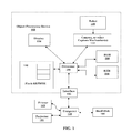
- FIG. 1 is a general block diagram of an object processing device and system for utilizing the present invention
- FIG. 2 is a flowchart of the general method of the present invention
- FIG. 3 is a flowchart of the object extraction stage of the method shown in FIG. 2 ;
- FIG. 4 illustrates a perspective projection in the pinhole camera model
- FIG. 5 illustrates and OpenGL projection and Normalized Device Coordinates (NDC);
- FIG. 6 ( a ) to ( d ) illustrates all four possible cases of the position of the projected model curve relative to the boundary of the object.
- FIG. 7 illustrates the composition of the camera motion.
- example embodiments relate to methods, devices, and computer-readable media for examining an image, particularly a digital image of one or more objects.
- the image is examined to estimate the pose (position and orientation) of a corresponding 3D object represented in the 2D image.
- Example embodiments create a binary mask of an image and extract a set of singlets from the binary mask. Each singlet will represent points in an inner and outer contour of the object.
- the set of singlets are connected into a mesh represented as a duplex matrix. Two duplex matrices are compared to produce a set of candidate poses.
- An object pose estimate is then produced and stored for later use, for example in a vision system for robotic parts assembly.
- FIG. 1 A schematic representation of an example object processing device 100 is shown in FIG. 1 .
- the object processing device 100 exchanges data with a host computer 150 by way of an intervening interface 102 .
- Application programs and an object processing device driver may also be stored for access on the host computer 150 .
- the object processing device driver controls conversion of the command data to a format suitable for the object processing device 100 and sends the converted command data to the object processing device 100 .
- the driver also receives and interprets various signals and data from the object processing device 100 , and provides necessary information to the user by way of the host computer 150 .
- the interface 102 When data is sent by the host computer 150 , the interface 102 receives the data and stores it in a receive buffer forming part of a RAM 104 .
- the RAM 104 can be divided into a number of sections, for example through addressing, and allocated as different buffers, such as a receive buffer or a send buffer.
- Data, such as digital image data can also be obtained by the object processing device 100 from the capture mechanism(s) 112 , the flash EEPROM 110 , or the ROM 108 .
- the capture mechanism(s) 112 can be a camera, for example, and generate a digital image by photographing one or more objects, such as a part to be used in manufacturing and/or assembly of a device such as a printer.
- a camera 112 can be controlled by robot 116 , for example, or a human, or can be automatically controlled by computer 150 , for example.
- the digital image of the object(s) can then be stored in the receive buffer or the send buffer of the RAM 104 .
- a processor 106 uses computer-executable instructions stored on a ROM 108 or on a flash EEPROM 110 , for example, to perform a certain function or group of functions, such as the method 200 ( FIG. 2 ) for example. Method 200 will be discussed in greater detail later herein.
- the processor 106 can implement the methodological acts of the method 200 on the digital image to extract features in the digital image and further analyze the image based on the extracted features.
- Further processing in an imaging pipeline may then be performed on the digital image before the image is displayed on a display 114 , such as an LCD display for example, or transferred to the host computer 150 , for printing on printer 162 , projected with projector 164 , or stored on hard disk 160 , for example.
- a display 114 such as an LCD display for example
- the host computer 150 for printing on printer 162 , projected with projector 164 , or stored on hard disk 160 , for example.
- the example method 200 and variations thereof disclosed herein can be implemented using non-transitory computer-readable media for carrying or having computer-executable instructions or data structures stored thereon.
- Such computer-readable media can be any available media that can be accessed by a processor of a general purpose or special purpose computer.
- Such computer-readable media can comprise RAM, ROM, EEPROM, CD-ROM or other optical disk storage, magnetic disk storage or other magnetic storage devices, or any other medium that can be used to carry or store program code in the form of computer-executable instructions or data structures and that can be accessed by a processor of a general purpose or special purpose computer. Combinations of the above should also be included within the scope of computer-readable media.
- Computer-executable instructions comprise, for example, instructions and data that cause a processor of a general purpose computer or a special purpose computer to perform a certain function or group of functions.
- Examples of special purpose computers include image processing devices such as digital cameras (an example of which includes, but is not limited to, the Epson R-D1 digital camera manufactured by Seiko Epson Corporation headquartered in Owa, Suwa, Nagano, Japan), digital camcorders, projectors, printers, scanners, copiers, portable photo viewers (examples of which include, but are not limited to, the Epson P-3000 or P-5000 portable photo viewers manufactured by Seiko Epson Corporation), or portable movie players, or some combination thereof, such as a printer/scanner/copier combination (examples of which include, but are not limited to, the Epson Stylus Photo RX580, RX595, or RX680, the Epson Stylus CX4400, CX7400, CX8400, or CX9400Fax, and the Epson AcuLaser® CX11NF manufactured by Seiko Epson Corporation) or a printer/scanner combination (examples of which include, but are not limited to, the Ep
- the first step in method 200 is inputting an image (step 210 ).
- the input images can be generated by robot 116 operating a camera (capture mechanism) 112 . If the input image contains one object, then it should preferably occupy at least 10% of the image area. If there is more than one object in the scene, the object of interest should preferably be at least two times larger than any other object in the image (scene).
- the input image can also be a CAD model of the object stored, for example, in RAM 104 or hard disk 160 .
- a plurality of images of the object are input and analyzed as described below. Each of the plurality of images preferably contains a view of the object that is different than a view shown in each of the other images. These plurality of images can be generated using the CAD model and/or robot 116 operating a camera.
- the Object Localization (step 212 ) and Object Extraction (step 214 stages of the present invention detect the object present in the image or scene and calculate its bounding-box.
- the Object Extraction stage also extracts the contours, both inner and outer, of the object.
- these steps process single-channel images 310 ( FIG. 3 ) that contain one or more objects on a plain background.
- These steps essentially discover areas of activity in the image and therefore may be sensitive to artifacts in the background.
- Objects in the input image are preferably single-color and with a minimum of contrast between the background and the objects. There is no additional limitation on the color of the background or that of the different objects. Some of the objects may be darker than the background and some may be brighter than it. Objects may have similar or different colors.
- the image 310 is divided into blocks of size S ⁇ S. S, which is a number of pixels. As an example, S is 8, but a different value can be selected according to the particular environment.
- This configuration parameter S is referred to herein as ACTIVITY.SCALE.
- This step then calculates the standard deviation and the average intensity for each block and returns the outputs as the two matrixes, standard (std) and average (ave).
- the present invention compares the elements of the matrix std to a threshold and identifies those elements that exceed a threshold, which can be selected for a particular environment. For example, this could be a color threshold. If 8 bits are used to represent a color depth, then the threshold would be set to somewhere between 0 and 255.
- the active area selection step identifies pixel blocks corresponding to the color object as contrasted to the plain background. The elements identified as exceeding a selected activity threshold are input to an Activity Map.
- the Region Analysis step 316 performs blob analysis on the Activity Map produced in previous step 314 .
- the parameters used in this step are size, controlled by OBJECTS.SIZE.MIN (default value is 0.001) and OBJECTS.SIZE.MAX (default value is 0.1), and number of candidate regions OBJECTS.COUNT (default value is 8).
- the size limitations are first divided by the square of ACTIVITY.SCALE in order to convert these configuration parameters from pixels to blocks.
- the Region Analysis step returns the bounding box for each object, as well as its first- and second-order means and area.
- each region is given an index.
- the indexes of the regions start from one but are not necessarily subsequent. In other words, there are missing index values, corresponding to regions which have not matched the size constraints.
- An index map carries the index assigned to each block. This map is called the Boundary Map. Any block given a non-zero index in the Boundary Map is a boundary block. The rest of the blocks are either background or represent the interior of an object. The interior blocks are detected in step 320 described hereinafter.
- the threshold calculation step 318 determines an optimal threshold for separating the contents of the boundary blocks for each region into foreground and background. This procedure is carried out through the following stages, done separately for each region.
- I is the set of all the points that fall into one of the boundary blocks for the region.
- the Threshold Calculation step 318 also determines if the object is darker than the background or vice versa. This determination is based on inspecting the pixels at the boundary of the bounding-box for each object and determining the number of them that exceed the threshold. If this number is over half the total number of pixels tallied, then it is determined that the object is darker than the background. This information OSMX_INVERSE is used in later steps. For example OSMX_INVERSE could be set to 1 if the object is darker than the background and 0 if it is lighter.
- the Interior Detection step 320 uses the Boundary Map and builds an Interior Map. This procedure starts with an all-zero Interior Map and for each region performs the following operation for each block in its bounding-box.
- Boundary Map does not enclose the Interior Map.
- unwanted “dents” may appear in the extracted object.
- the Boundary Closure step 322 closes the Boundary Map for each region by performing the following operation within the bounding-box of each region,
- the Object Extraction step 324 extracts the objects based on the Boundary Map and the Interior Map. This procedure performs the following operations for each object, within its own bounding-box.
- Duplet Creation is the last step in the present invention where the actual images are used. After this stage, the work is done on Duplet Matrixes and other feature points and vectors.
- Duplet Creation contains three sub-blocks of Contour-Tracing, Singlet Detection, and Duplet Creation, each described below.
- Contour-Tracing is the procedure that traces all the contours returned by the Object Extraction stage. The information collected at this stage is used in the Singlet Detection procedure. Any known contour-tracing algorithm can be used in the present invention, which is not limited to a particular algorithm. Examples of contour-tracing algorithms that may be utilized include Square Tracing, Moore-Neighbor, Radial Sweep. In a preferred embodiment Theo Pavlidis' algorithm is used.
- TRACE_WINDOW SINGLET_DISTANCE
- SINGLET_DISTANCE SINGLET_DISTANCE
- Duplet Creation is the procedure that combines the detected singlets into duplets.
- the process of creating the duplets contains the following steps:
- Duplet Comparison is the process of comparing the items in two Duplet Matrixes and producing a list of matches, and therefore a first list of candidate poses. Assuming that the two Duplet Matrixes are D1 and D2, the process is performed as follows:
- Candidate Clustering ( FIG. 2 , step 220 )
- Candidate Clustering is the process taking in the pose candidates produced through Duplet Comparison and estimating a limited number of poses which are each represented by a large set of the candidates. This procedure contains two stages, Scale-Angle Clustering, and X-Y Clustering, both described below.
- the aim of this stage is to produce a list of candidate (scale,angle) pairs based on the candidate poses produces through Duplet Comparison.
- the output of the Scale-Angle Clustering stage is a set of (scale,angle) candidates.
- the X-Y Clustering stage is the process of adding translation information to the candidates, as follows for each (scale,angle) candidate.
- Overlap Consideration is only functional if OVERLAP is non-negative.
- the Overlap Consideration is done as follows,
- a Contour-Duplets Database (CDDB) file contains a list of Duplet Matrixes, each accompanying an elevation and azimuth.
- CDDB Contour-Duplets Database
- the algorithm described above will perform Duplet Creation on the training images ( FIG. 2 , 224 ) and will then store the resulting Duplet Matrixes in the CDDB 222 each accompanied with the elevation-azimuth representation. These samples are called the views.
- CDDB files in practice are accompanied with a file that contains details about the training images. These details are necessary for producing different visualizations and are not needed for the regular operation of the algorithm.
- the procedure is repeated for each view in the database.
- the final output of the algorithm is the CDDBC.SEARCH.CANDIDATES.TOTAL number of candidates with the highest corresponding confidence values.
- the angular representation of the views that have produced each candidate are then appended to each candidate, thus producing the (elevation, azimuth, angle, scale, dx, dy, confidence) representation of the pose.
- the results of the object detection steps outlined above are these representations of the pose, which are pose estimates, and are stored in memory, e.g. RAM 104 or hard disk 160 . These pose estimates can then be used in robot recognition of the object/part in the assembly of a product.
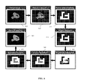
- Model View is the image of the matching training image modified to reflect scale, angle, and translation as well.
- Overlay is the overlay of the Model View on the query image.
- the training procedure requires images showing the object of interest in different poses, as governed by different parameters.
- a practical and more convenient method for producing these images is through the sample simulator 228 , which is a three-dimensional visualization tool that produces the 3D views of the objects.
- the Configuration Utility is an interactive tool thatfinds the proper values for these parameters and sets them accordingly using minimum intuitive input from the user.
- the pose refinement of the present invention is modeled as an alignment problem.
- a 3D model of the object of interest i.e. the part that the robot has to identify and pick up, and camera parameters of the camera 112 that is used to image the object.
- the goal is to find the 3D (Euclidean, 6 degrees of freedom) transformation that is to be applied to the model so that it coincides with the object of interest in the image.
- the pose refinement is implemented as iterative optimization problem of a cost function.
- the cost function may involve an image matching cost that aligns or matches local feature points or boundaries feature points.
- the camera projective model of the present invention is based on a pinhole camera model.
- the pinhole camera is the simplest, and the ideal, model of camera function. It has an infinitesimally small hole through which light enters before forming an inverted image on the camera surface facing the hole.
- the perspective projection is the projection of a three-dimensional object onto a two-dimensional image plane.
- the focal plane is one particular plane that is parallel to the image plane. Assuming the pinhole camera coordinate is aligned with world coordinates, simple geometry shows:
- the projection model from the camera frame coordinate to the pixel (image) coordinates is derived as:
- Sx and Sy are scaling factors in the x and y directions from the focal sensor plane to image or pixel coordinate.
- the Sx and Sy scaling factors are proportional to the CCD sensor cell width and height, and resolution. We can calibrate the camera to obtain the model scaling factor ⁇ x and ⁇ y .
- equation (3) can be represented as:
- the image Jacobian matrix should be constructed based on the relationship between the velocity of some object in the workspace and the corresponding changes that occur in the observed image of the workspace.
- the image Jacobian matrix is estimated as follows.
- Step 1 Using the quotient rule
- Step 2 The perspective projection equations can be rewritten to give expressions for x and y as
- Step 3 The velocity of (the fixed point) P relative to the camera frame is given by
- the present invention preferably uses OpenGL, which can execute high-speed rendering and hidden-line removal with existing hardware.
- OpenGL can store the depth information at each pixel. Using this information the 3D points corresponding to each contour point are calculated.
- FIG. 5 illustrates the OpenGL projection and Normalized Device Coordinates (NDC).
- NDC Normalized Device Coordinates
- OpenGL is used in a preferred embodiment, the present invention is not limited to this rendering application programming interface (API), and other rendering APIs such as DirectX, ray tracing, etc. may be utilized.
- a 3D point in a truncated pyramid frustum is mapped to a cube (NDC); the x-coordinate from [1, r] to [ ⁇ 1, 1], the y-coordinate from [b, t] to [ ⁇ 1, 1] and the z-coordinate from [n, f] to [ ⁇ 1, 1].
- the projection matrix transforms a vertex in eye coordinate system to the clip coordinate system.
- OpenGL is used only to project the model. All the equations by default are derived using the real camera model.
- the pose refinement method of the present invention minimizes an energy based cost function.
- the cost function is defined with a minimum so that the model projection using 3D pose (6DoF) coincides with the object of interest in the image.
- I(x,y) is the input image
- T(x,y) is the binary mask image of the model projection with given 3D pose.
- the binary mask T(x,y) image is the projection of the model for a given 3D pose and camera parameters with the definition as follows:
- T ⁇ ( x , y ) ⁇ 1 if ⁇ ⁇ ( x , y ) ⁇ inside 0 outside ( 17 )
- the OpenGL can execute high-speed rendering of the binary mask image by projecting the object model into a 2D virtual image.
- the u 1 and u 2 are the mean value of the input image inside and outside the object mask defined as:
- the projected model contour curve C can be obtained from T(x,y), which separates the image into “inside” object and “outside” object.
- F 1 is the fitting energy inside object and F 2 is the fitting energy outside object.
- FIG. 6 illustrates all possible cases of the position of the projected model curve.
- the additional constraining term may be defined as:
- ⁇ 1 M ⁇ ⁇ w i * ( ( u j - p jx ) 2 + ( v j + p jy ) 2 ) ( 19 )
- ⁇ j is the weight for feature match, which may be the match confidence or score
- the ⁇ ⁇ may be the Euclidean distance in the image coordinate.
- the equation (17) or match energy minimization can provide the initial pose estimation for refinement. It may be also used as a constraining term for pose refinement so that it can improve the convergence and robustness.
- ⁇ is a weight function to balance energy between E c and E match .
- the partial differentials of E with respect to the pose parameter r can be computed using the chain rule.
- ⁇ 1 M ⁇ ⁇ w i * ( ( u j - p jx ) 2 + ( v j - p jy ) 2 )
- ⁇ x ⁇ r i ⁇ ⁇ and ⁇ ⁇ ⁇ y ⁇ r i can be obtained as follows.
- ⁇ T ⁇ ( x , y ) ⁇ x ⁇ ⁇ and ⁇ ⁇ ⁇ T ⁇ ( x , y ) ⁇ y are differential of T(x,y) in x and y direction.
- T(x,y) is the binary mask of projection of the model as defined in equation (17).
- the gradient of T(x,y) are zero except on the boundary C.
- the match energy is the cost function to measure the distance the matched feature points in image coordinate between the feature points in the input image and in the projected virtual image.
- u . - ⁇ x Z c ⁇ v x + u Z c ⁇ v z + uv ⁇ y ⁇ wx - ⁇ x 2 + u 2 ⁇ x ⁇ w y + ⁇ x ⁇ v ⁇ y ⁇ w z v .
- the partial equation are derived in image and camera coordinate
- the e and J are obtained by concatenating e c , ⁇ e match and J c and ⁇ J match respectively.
- the transformation between object coordinate to camera coordinate may be representation by a transformation.
- X ( t ) R ( t ) X 0 +T ( t ) (37)
- the pose parameter update for iteration n is obtained by calculating g(t n , t n-1 ).
- a stepsize function is used to adjust the convergence speed.
- the pose estimation is modeled as an optimization or minimization of an energy function. Iteratively pose updates will be calculated to minimize the energy.
- the following is an exemplary implementation of the method detailed above:
- Step 1 Input image, model, camera parameters
- Step 2 Get initial pose parameters
- Step 3 Project model into virtual image by OpenGL using given pose parameters.
- the binary mask image T(x,y) and corresponding depth information/map are obtained.
- Step 4 Calculate the velocity screw for iteratively updating the pose.
- (i) Calculate the mean value inside and outside the object by equation (18).
- (ii). Get the contour C from binary mask and 3D contour points using depth information.
- (iii) Calculate the gradient ⁇ T(x,y) in x and y direction for contour points.
- (iv) Calculate image Jacobian matrix using equation (26)
- (iv) Calculate the gradient flow using equation (27) and get the control input (velocity screw) by equation (35) using the Gaussian Newton method
- Step 5 Calculate relative displacement using the control input (velocity screw) and given stepsize by equation (45)
- Step 6 Update the pose parameters by equation (46) and (47)
- Step 7 If changes of the pose parameters are very small or if maximum iterations are reached, go to END, else go back Step 3.
- Step 8 END
Landscapes
- Engineering & Computer Science (AREA)
- Physics & Mathematics (AREA)
- General Physics & Mathematics (AREA)
- Theoretical Computer Science (AREA)
- Computer Vision & Pattern Recognition (AREA)
- Multimedia (AREA)
- Image Analysis (AREA)
- Image Processing (AREA)
- Manipulator (AREA)
Abstract
Description
-
- 1. Produce a 256-bin histogram for the contents of I.
- 2. Calculate t as the average of I.
- 3. Threshold I using the value of t and produce I+ and I−.
- 4. Calculate t+ as the average of I+.
- 5. Calculate t− as the average of I−.
- 6. Calculate t* as (t−+t−)/2.
- 7. If the difference between t and t* is less than one, then return t as the threshold, otherwise set t=t* and go to 3.
The threshold calculated at this stage (OSMX_THRESHOLD) is used in later steps.
-
- 1. If the block is not in the Boundary Map, and if the average for the block is over or under (depending on how OE_INVERSE is set) the OE_THRESHOLD, and if this block has at least one 4-connected neighbors in the Boundary Map, then mark this block in the Interior Map.
-
- 1. If the block is not in either the Boundary Map or the Interior Map and if it has at least one 4-connected neighbor in the Interior Map, then mark this block in the Boundary Map.
-
- 1. If this block is marked in the Interior Map, then set all the pixels corresponding to it as belonging to the object.
- 2. If this block is marked in the Boundary Map, then set all the pixels corresponding to it as belonging to the object if the average for the block is over or under (depending on how OE_INVERSE is set) the OE_THRESHOLD.
-
- 1. Find the average X and Y coordinates for the TRACE_WINDOW points around the point on the contour.
- 2. Connect the point on the contour to the two points which are TRACE_WINDOW away to the left and to the right.
- 3. Find the two angles; call them the in-coming angle and the out-going angle.
- 4. Find the inner product of the two vectors which represent the incoming angle and the outgoing angle. Change the sign of this inner product and call it the Curvature.
- 5. Mark this point as a singlet if it has the highest Curvature in the SINGLET_DISTANCE points around it.
- 6. Store the X and Y coordinates for each singlet, as well as the in-coming and out-going angles and the Curvature corresponding to them.
-
- 1. Produce the matrix D, with its (i,j) element containing the distance between the i-th and the j-th singlets.
- 2. Change all the elements of D that are below the minimum threshold or over the maximum threshold as NAN (Not a Number, an identifier that denotes a variable that has not been initialized). The minimum and the maximum thresholds are calculated as DISTANCE.MIN (default value is 0.01) and DISTANCE.MAX (default value is 0.25) multiplied with the smallest dimension of the image, respectively.
- 3. Produce an Sx1 array of all zeros and call it deg. deg(s) will contain the number of singlets that are connected to the s-th singlet.
- 4. Scan D until it only contains NANs or when a maximum number for the singlets is specified and that the maximum is reached.
- 5. Find the smallest element of D. Call that (s1,s2). Increment both deg(s1) and deg(s2). If either deg(s1) or deg(s2) is larger than the maximum degree DEGREE (default is 10), then set all elements in the row and column which correspond to the singlet as NAN. For example, if deg(s1) is larger than DEGREE, then for all s set D(s,s1) and D(s1,s) to NAN.
- 6. For the pair (s1,s2), calculate the angle that connects them together as well as the length of the line which connects them, call them angle and distance, respectively. Subtract angle from the in-coming and out-going angles of a temporary copy of both singlets. Now, the duplet will be represented as, <angle, distance, s1.in-coming, s1.out-going, s2.in-coming, s2.out-going>.
- 7. Return the Duplet Matrix.
-
- 1. For any duplets d1 in D1 and d2 in D2, determine if these condition are all satisfied,
|d1.s1.in-coming−d2.s1.in-coming|<THRESHOLD,
|d1.s1.out-going−d2.s1.out-going|<THRESHOLD,
|d1.s2.in-coming−d2.s2.in-coming|<THRESHOLD,
|d1.s2.out-going−d2.s2.out-going|<THRESHOLD.- Here, THRESHOLD is determined by the configuration variable DUPLETS.THRESHOLD.
- If these conditions are met, then add the candidate pose (d1.length/d2.length, d1.angle-d2.angle) to the list of candidates. Also take note of the X and Y coordinates of the two singlets and of both duplets. Tag this candidate as “straight”.
- 2. Similarly, determine if these conditions are satisfied,
|d1.s1.in-coming−d2.s2.in-coming|<THRESHOLD,
|d1.s1.out-going−d2.s2.out-going|<THRESHOLD,
|d1.s2.in-coming−d2.s1.in-coming|<THRESHOLD,
|d1.s2.out-going−d2.s1.out-going|<THRESHOLD,- in which case, a similar candidate pose will be added to the list, except for the angle which will be recorded as d1.angle-d2.angle-pi. This candidate will be tagged as “reverse”.
- 3. Pass the list of candidates to the clustering stage described next.
- 1. For any duplets d1 in D1 and d2 in D2, determine if these condition are all satisfied,
-
- 1. Produce S_L by calculating the base BASE logarithm of the values of S.
- 2. Produce the histograms of A and S_L, independently. Each histogram will contain BINS bins. The histogram for A will cover the range of −pi to pi. S_L will be analyzed in the range of SCALE.MIN and SCALE.MAX, both in base BASE.
- 3. Mark a point on either histogram as a ‘peak’ if it is higher than the D points to its right and higher or equal to the D points to its left.
- 4. Select the C1 highest peaks for each histogram independently.
- 5. Intersect every scale candidate with every angle candidate and produce a list of scale-angle candidates. Pass this list to the X-Y clustering stage. For each scale-angle candidate, also send the positions of the singlets in the matching duplets which resulted in this pair.
- 6. Calculate the confidence for each scale-angle candidate as the number of pairs of duplet matches which represent it divided by the smallest of the number of duplets in the two Duplet Matrixes.
- 7. If the number of scale-angle candidates exceeds C2, then pick the C2 ones with the highest confidence.
-
- 1. Modify the singlet positions for this candidate so that the center of the axis systems moves to the center of the image. This process will be carried out independently for the two Duplet Matrixes.
- 2. Rotate the query singlet positions by angle.
- 3. Scale the query singlets by scale.
- 4. Find the difference in X and Y, independently, for the singlet positions between the query and the reference. Call these dx and dy arrays.
- 5. At this stage, the dx-dy pairs can undergo a two-dimensional clustering algorithm similar to the one carried out on scale-angle pairs, or a quicker operation can follow.
- 6. Find the mean of dx and dy, independently and append this information to the scale-angle pair, thus producing the pose candidate (angle,scale,dx,dy,confidence). The confidence for this pose candidate will remain equal to the confidence for scale-angle pair.
- 7. If required by the configuration parameters, as described below, perform overlap examination.
- 8. Pick C2 candidates which correspond to the highest values of confidence and report them to the next stage.
-
- 1. Transform the reference bounding-box according to the (angle,scale,dx,dy,confidence) information. Find the smallest rectangle that covers the rotated, scaled, and shifted bounding-box.
- 2. Find the smallest rectangle that covers both the modified bounding-box of the reference and the bounding-box of the query. Call the area of this rectangle A.
- 3. Mark this candidate as inappropriate if min(A1,A2)/A is below OVERLAP. Here, A1 and A2 are the area of the modified bounding-box of the reference and the area of the query.
- 4. Eliminate candidates marked as inappropriate from the list.
where (x0, y0) is the projection of the origin point of camera coordinate in the image or pixel coordinate.
{dot over (x)}=−v x −w y z+w z y
{dot over (y)}=−v y −w z x+w x z
ż=−v z −w x y+w y x (11)
These equations can be written in image Jacobian matrix form.
E=F 1 +F 2 =∫T(x,y)*(I(x,y)−u 1)2 dxdy+∫(1−T(x,y))*(I(x,y)−u 2)2 dxdy (16)
inf{F 1(C)+F 2(C)}≈0≈F 1(C 0)+F 2(C 0).
where Ain=∫T(x,y)dxdy is the area inside the object.
where Aout=∫(1−T(x,y))dxdy is the area outside the object.
Therefore, we can get:
The binary mask T(x,y) image is the projection of model for given 3D pose and camera parameters.
From the image Jacobian matrix in equation (12), the
can be obtained as follows.
The
are differential of T(x,y) in x and y direction.
The velocity of (the fixed point) P relative to the camera frame is given by
{dot over (P)}=−Ω×P−V
The
can be re-written in the form of the image Jacobian matrix as follows.
Starting with an initial guess for the minimum, the method proceeds by the iterations.
r n =r n-1 +Δr (33)
where the increment Δr is the solution to the normal equations.
e=−J r Δr (34)
The task of finding Δr minimizing the sum of squares
min∥e+J r Δr∥
The increment Δr is then calculated by
Δr=−(J r T J r)−1 J r T e (35)
e c=(I(x,y)−u 1)2−(I(x,y)−u 2)2
and
J c =[J 1 ,J 2 ,J 3 ,J 4 ,J 5 ,J 6]
and
The increment Δr will be calculated by
Δr=−(J T J)1 J T e
X(t)=R(t)X 0 +T(t) (37)
X(t 2)=g(t 2 ,t 1)X(t 1) (39)
X(t 3)=g(t 3 ,t 2)X(t 2)=g(t 3 ,t 2)g(t 2 ,t 1)X(t 1) (40)
X(t 3)=g(t 3 ,t 1)X(t 1) (41)
g(t 3 ,t 1)=g(t 3 ,t 2)g(t 2 ,t 1) (42)
g(t 3 ,t 1)−g(t n ,t n-1)g(t n-1 ,t 1) (43)
and the new transformation matrix from object to camera coordinate will be
g(t n ,t 1)=g(t n ,t n-1)g(t n-1 ,t 1) (47)
Claims (20)
|d1.s1.in-coming−d2.s1.in-coming|<THRESHOLD,
|d1.s1.out-going−d2.s1.out-going|<THRESHOLD,
|d1.s2.in-coming−d2.s2.in-coming|<THRESHOLD,
|d1.s2.out-going−d2.s2.out-going|<THRESHOLD,
|d1.s1.in-coming−d2.s1.in-coming|<THRESHOLD,
|d1.s1.out-going−d2.s1.out-going|<THRESHOLD,
|d1.s2.in-coming−d2.s2.in-coming|<THRESHOLD,
|d1.s2.out-going−d2.s2.out-going|<THRESHOLD,
Priority Applications (3)
| Application Number | Priority Date | Filing Date | Title |
|---|---|---|---|
| US13/220,851 US8467596B2 (en) | 2011-08-30 | 2011-08-30 | Method and apparatus for object pose estimation |
| JP2012162378A JP6011102B2 (en) | 2011-08-30 | 2012-07-23 | Object posture estimation method |
| CN2012102796647A CN103150544A (en) | 2011-08-30 | 2012-08-07 | Method and apparatus for object pose estimation |
Applications Claiming Priority (1)
| Application Number | Priority Date | Filing Date | Title |
|---|---|---|---|
| US13/220,851 US8467596B2 (en) | 2011-08-30 | 2011-08-30 | Method and apparatus for object pose estimation |
Publications (2)
| Publication Number | Publication Date |
|---|---|
| US20130051626A1 US20130051626A1 (en) | 2013-02-28 |
| US8467596B2 true US8467596B2 (en) | 2013-06-18 |
Family
ID=47743794
Family Applications (1)
| Application Number | Title | Priority Date | Filing Date |
|---|---|---|---|
| US13/220,851 Expired - Fee Related US8467596B2 (en) | 2011-08-30 | 2011-08-30 | Method and apparatus for object pose estimation |
Country Status (3)
| Country | Link |
|---|---|
| US (1) | US8467596B2 (en) |
| JP (1) | JP6011102B2 (en) |
| CN (1) | CN103150544A (en) |
Cited By (10)
| Publication number | Priority date | Publication date | Assignee | Title |
|---|---|---|---|---|
| US20130121526A1 (en) * | 2011-11-11 | 2013-05-16 | Microsoft Corporation | Computing 3d shape parameters for face animation |
| US20130156262A1 (en) * | 2011-12-19 | 2013-06-20 | Yuichi Taguchi | Voting-Based Pose Estimation for 3D Sensors |
| US20130300835A1 (en) * | 2012-05-14 | 2013-11-14 | Omron Scientific Technologies, Inc. | Method and Apparatus to Guarantee Minimum Contrast for Machine Vision System |
| US20160048970A1 (en) * | 2014-08-15 | 2016-02-18 | Maziar Loghman | Multi-resolution depth estimation using modified census transform for advanced driver assistance systems |
| US20170076462A1 (en) * | 2015-09-15 | 2017-03-16 | Korea Electronics Technology Institute | Robust region segmentation method and system using the same |
| US9969082B1 (en) * | 2016-01-05 | 2018-05-15 | Boston Dynamics, Inc. | Robotic systems and methods for task scoring and selection |
| US20190332084A1 (en) * | 2018-04-26 | 2019-10-31 | Liberty Reach Inc. | Non-contact method and system for controlling an industrial automation machine |
| US10909769B1 (en) * | 2019-09-18 | 2021-02-02 | Industry Academy Cooperation Foundation Of Sejong University | Mixed reality based 3D sketching device and method |
| US11295532B2 (en) | 2018-11-15 | 2022-04-05 | Samsung Electronics Co., Ltd. | Method and apparatus for aligning 3D model |
| EP4081938A4 (en) * | 2020-01-29 | 2024-03-20 | Intrinsic Innovation LLC | SYSTEMS AND METHODS FOR POSE DETECTION AND MEASURING |
Families Citing this family (36)
| Publication number | Priority date | Publication date | Assignee | Title |
|---|---|---|---|---|
| US8503720B2 (en) | 2009-05-01 | 2013-08-06 | Microsoft Corporation | Human body pose estimation |
| US8942917B2 (en) | 2011-02-14 | 2015-01-27 | Microsoft Corporation | Change invariant scene recognition by an agent |
| JP6323993B2 (en) * | 2012-08-28 | 2018-05-16 | キヤノン株式会社 | Information processing apparatus, information processing method, and computer program |
| US10572774B2 (en) * | 2012-12-06 | 2020-02-25 | Toyota Motor Engineering & Manufacturing North America. Inc. | Methods and robots for adjusting object detection parameters, object recognition parameters, or both object detection parameters and object recognition parameters |
| US9857470B2 (en) | 2012-12-28 | 2018-01-02 | Microsoft Technology Licensing, Llc | Using photometric stereo for 3D environment modeling |
| US9940553B2 (en) | 2013-02-22 | 2018-04-10 | Microsoft Technology Licensing, Llc | Camera/object pose from predicted coordinates |
| US9852512B2 (en) | 2013-03-13 | 2017-12-26 | Electronic Scripting Products, Inc. | Reduced homography based on structural redundancy of conditioned motion |
| US8970709B2 (en) * | 2013-03-13 | 2015-03-03 | Electronic Scripting Products, Inc. | Reduced homography for recovery of pose parameters of an optical apparatus producing image data with structural uncertainty |
| GB2532494A (en) * | 2014-11-21 | 2016-05-25 | The Chancellor Masters And Scholars Of The Univ Of Oxford | Localising portable apparatus |
| JP2017182274A (en) | 2016-03-29 | 2017-10-05 | セイコーエプソン株式会社 | Information processing device and computer program |
| JP2017187882A (en) | 2016-04-04 | 2017-10-12 | セイコーエプソン株式会社 | Computer program used for image processing |
| US11577159B2 (en) | 2016-05-26 | 2023-02-14 | Electronic Scripting Products Inc. | Realistic virtual/augmented/mixed reality viewing and interactions |
| WO2018072208A1 (en) * | 2016-10-21 | 2018-04-26 | Abb Schweiz Ag | Method, electronic device and system of picking an object from a container |
| JP2018081410A (en) | 2016-11-15 | 2018-05-24 | セイコーエプソン株式会社 | Computer program |
| US10373369B2 (en) * | 2017-03-16 | 2019-08-06 | Qualcomm Technologies, Inc. | Three-dimensional pose estimation of symmetrical objects |
| US10621751B2 (en) | 2017-06-16 | 2020-04-14 | Seiko Epson Corporation | Information processing device and computer program |
| CN109559271B (en) * | 2017-09-26 | 2023-02-28 | 富士通株式会社 | Method and device for optimizing depth image |
| CN107943458B (en) * | 2017-11-20 | 2020-07-24 | 上海木木聚枞机器人科技有限公司 | Robot development system |
| CN108304762B (en) * | 2017-11-30 | 2021-11-05 | 腾讯科技(深圳)有限公司 | Human body posture matching method and device, storage medium and terminal |
| US10552665B2 (en) | 2017-12-12 | 2020-02-04 | Seiko Epson Corporation | Methods and systems for training an object detection algorithm using synthetic images |
| US10970425B2 (en) | 2017-12-26 | 2021-04-06 | Seiko Epson Corporation | Object detection and tracking |
| US10410089B2 (en) | 2018-01-19 | 2019-09-10 | Seiko Epson Corporation | Training assistance using synthetic images |
| CN108564616B (en) * | 2018-03-15 | 2020-09-01 | 中国科学院自动化研究所 | Fast robust RGB-D indoor three-dimensional scene reconstruction method |
| US10311833B1 (en) | 2018-03-27 | 2019-06-04 | Seiko Epson Corporation | Head-mounted display device and method of operating a display apparatus tracking an object |
| US10769437B2 (en) | 2018-04-10 | 2020-09-08 | Seiko Epson Corporation | Adaptive sampling of training views |
| US10878285B2 (en) | 2018-04-12 | 2020-12-29 | Seiko Epson Corporation | Methods and systems for shape based training for an object detection algorithm |
| CN109345504A (en) * | 2018-08-07 | 2019-02-15 | 浙江大学 | A bottom-up multi-person pose estimation method using bounding box constraints |
| CN109190537B (en) * | 2018-08-23 | 2020-09-29 | 浙江工商大学 | A multi-person pose estimation method based on mask-aware deep reinforcement learning |
| US10634918B2 (en) | 2018-09-06 | 2020-04-28 | Seiko Epson Corporation | Internal edge verification |
| CN109344750B (en) * | 2018-09-20 | 2021-10-22 | 浙江工业大学 | A three-dimensional object recognition method for complex structures based on structure descriptors |
| CN111402191B (en) * | 2018-12-28 | 2023-04-18 | 阿里巴巴集团控股有限公司 | Target detection method, device, computing equipment and medium |
| CN110276805A (en) * | 2019-06-28 | 2019-09-24 | 联想(北京)有限公司 | A kind of data processing method and electronic equipment |
| JP7660387B2 (en) * | 2020-06-15 | 2025-04-11 | エヌビディア コーポレーション | Object-to-robot pose estimation from a single RGB image |
| CN112894815B (en) * | 2021-01-25 | 2022-09-27 | 西安工业大学 | Optimal pose detection method for object grasping by visual servo robotic arm |
| US11770495B2 (en) * | 2021-08-13 | 2023-09-26 | GM Global Technology Operations LLC | Generating virtual images based on captured image data |
| CN114083545B (en) * | 2022-01-24 | 2022-07-01 | 之江实验室 | Moving object robot grabbing method and device based on visual perception |
Citations (7)
| Publication number | Priority date | Publication date | Assignee | Title |
|---|---|---|---|---|
| US7016539B1 (en) * | 1998-07-13 | 2006-03-21 | Cognex Corporation | Method for fast, robust, multi-dimensional pattern recognition |
| US7158656B2 (en) * | 1999-03-08 | 2007-01-02 | Vulcan Patents Llc | Three dimensional object pose estimation which employs dense depth information |
| US20070162164A1 (en) * | 2005-12-22 | 2007-07-12 | Behzad Dariush | Reconstruction, Retargetting, Tracking, And Estimation Of Pose Of Articulated Systems |
| US20100259537A1 (en) | 2007-10-12 | 2010-10-14 | Mvtec Software Gmbh | Computer vision cad models |
| US7822264B2 (en) | 2003-08-15 | 2010-10-26 | Scape A/S | Computer-vision system for classification and spatial localization of bounded 3D-objects |
| US7957583B2 (en) * | 2007-08-02 | 2011-06-07 | Roboticvisiontech Llc | System and method of three-dimensional pose estimation |
| US20110157178A1 (en) * | 2009-12-28 | 2011-06-30 | Cuneyt Oncel Tuzel | Method and System for Determining Poses of Objects |
Family Cites Families (1)
| Publication number | Priority date | Publication date | Assignee | Title |
|---|---|---|---|---|
| CN102136139B (en) * | 2010-01-22 | 2016-01-27 | 三星电子株式会社 | Targeted attitude analytical equipment and targeted attitude analytical approach thereof |
-
2011
- 2011-08-30 US US13/220,851 patent/US8467596B2/en not_active Expired - Fee Related
-
2012
- 2012-07-23 JP JP2012162378A patent/JP6011102B2/en active Active
- 2012-08-07 CN CN2012102796647A patent/CN103150544A/en active Pending
Patent Citations (7)
| Publication number | Priority date | Publication date | Assignee | Title |
|---|---|---|---|---|
| US7016539B1 (en) * | 1998-07-13 | 2006-03-21 | Cognex Corporation | Method for fast, robust, multi-dimensional pattern recognition |
| US7158656B2 (en) * | 1999-03-08 | 2007-01-02 | Vulcan Patents Llc | Three dimensional object pose estimation which employs dense depth information |
| US7822264B2 (en) | 2003-08-15 | 2010-10-26 | Scape A/S | Computer-vision system for classification and spatial localization of bounded 3D-objects |
| US20070162164A1 (en) * | 2005-12-22 | 2007-07-12 | Behzad Dariush | Reconstruction, Retargetting, Tracking, And Estimation Of Pose Of Articulated Systems |
| US7957583B2 (en) * | 2007-08-02 | 2011-06-07 | Roboticvisiontech Llc | System and method of three-dimensional pose estimation |
| US20100259537A1 (en) | 2007-10-12 | 2010-10-14 | Mvtec Software Gmbh | Computer vision cad models |
| US20110157178A1 (en) * | 2009-12-28 | 2011-06-30 | Cuneyt Oncel Tuzel | Method and System for Determining Poses of Objects |
Non-Patent Citations (10)
| Title |
|---|
| Active Contours Without Edges, Tony F. Chan, Member, IEEE and Luminita A. Vese, IEEE Transactions on Image Processing, vol. 10. No. 2, (pp. 266-277) Feb. 2001. |
| Anthony J. Yezzi and Stefano Soatto, "Structure From Motion for Scenes Without Features", IEEE, Computer Society Conference on Computer Vision and Pattern Recognition, vol. 1, Jun. 2003, pp. 1-8. * |
| Björn Johansson and Anders Moe, "Patch-Duplets for Object Recognition and Pose Estimation", IEEE, Proceedings of the Second Canadian Conference on Computer and Robot Vision, May 2005, pp. 9-16. * |
| Fredrik Viksten, "Object Pose Estimation using Patch-Duplet/SIFT Hybrids", Proceedings of the 11th IAPR Conference on Machine Vision Applications, 2009, pp. 134-137. * |
| Fredrik Viksten, Per-Erik Forssen, Bjorn Johansson, and Anders Moe, "Comparison of Local Image Descriptors for Full 6 Degree-of-Freedom Pose Estimation", IEEE International Conference on Robotics and Automation, May 2009, pp. 2779-2786. * |
| Matching and Pose Refinement with Camera Pose Estimates, Satyan Coorg and Seth Teller, MIT Computer Graphics Group, 545 Technology Square NE43-217, Cambridge, MA 02139, Proc. 1997 Image Understanding Workshop, (pp. 857-862), May 1997. |
| Pose Estimation via Gauss-Newton-on-manifold, Pei Yean Lee and John B. Moore, Department of System Engineering, RSISE, Australian National University, ACT 0200, Australia and National ICT Australia Limited, Locked Bag 8001, Canberra, ACT 2601, Australia, Jan. 2005. |
| Pose Refinement of Active Models Using Forces in 3D, A. D. Worrall, G. D. Sullivan and K. D. Baker, Dept. of Computer Science, University of Reading, Reading, UK, RG6 2AY, ECCV (1) (pp. 341-350), Jan. 1994. |
| Robust 3D Pose Estimation and Efficient 2D Region-Based Segmentation from a 3D Shape Prior, Samuel Dambreville, Romeil Sandhu, Anthony Yezzi, and Allen Tannenbaum, Georgia Institute of Technology, In Proc. European Conf. on Computer Vision (ECCV), vol. 5303, (pp. 169-182), Jan. 2008. |
| Tony F. Chan and Luminita A. Vese, "Active Contours Without Edges", IEEE, Transactions on Image Processing, vol. 10, No. 2, Feb. 2001, pp. 266-277. * |
Cited By (17)
| Publication number | Priority date | Publication date | Assignee | Title |
|---|---|---|---|---|
| US9959627B2 (en) | 2011-11-11 | 2018-05-01 | Microsoft Technology Licensing, Llc | Computing 3D shape parameters for face animation |
| US20130121526A1 (en) * | 2011-11-11 | 2013-05-16 | Microsoft Corporation | Computing 3d shape parameters for face animation |
| US9123144B2 (en) * | 2011-11-11 | 2015-09-01 | Microsoft Technology Licensing, Llc | Computing 3D shape parameters for face animation |
| US8908913B2 (en) * | 2011-12-19 | 2014-12-09 | Mitsubishi Electric Research Laboratories, Inc. | Voting-based pose estimation for 3D sensors |
| US20130156262A1 (en) * | 2011-12-19 | 2013-06-20 | Yuichi Taguchi | Voting-Based Pose Estimation for 3D Sensors |
| US20130300835A1 (en) * | 2012-05-14 | 2013-11-14 | Omron Scientific Technologies, Inc. | Method and Apparatus to Guarantee Minimum Contrast for Machine Vision System |
| US20160048970A1 (en) * | 2014-08-15 | 2016-02-18 | Maziar Loghman | Multi-resolution depth estimation using modified census transform for advanced driver assistance systems |
| US9754377B2 (en) * | 2014-08-15 | 2017-09-05 | Illinois Institute Of Technology | Multi-resolution depth estimation using modified census transform for advanced driver assistance systems |
| US20170076462A1 (en) * | 2015-09-15 | 2017-03-16 | Korea Electronics Technology Institute | Robust region segmentation method and system using the same |
| US10489675B2 (en) * | 2015-09-15 | 2019-11-26 | Korea Electronics Technology Institute | Robust region segmentation method and system using the same |
| US9969082B1 (en) * | 2016-01-05 | 2018-05-15 | Boston Dynamics, Inc. | Robotic systems and methods for task scoring and selection |
| US20190332084A1 (en) * | 2018-04-26 | 2019-10-31 | Liberty Reach Inc. | Non-contact method and system for controlling an industrial automation machine |
| US11314220B2 (en) * | 2018-04-26 | 2022-04-26 | Liberty Reach Inc. | Non-contact method and system for controlling an industrial automation machine |
| US11295532B2 (en) | 2018-11-15 | 2022-04-05 | Samsung Electronics Co., Ltd. | Method and apparatus for aligning 3D model |
| US10909769B1 (en) * | 2019-09-18 | 2021-02-02 | Industry Academy Cooperation Foundation Of Sejong University | Mixed reality based 3D sketching device and method |
| EP4081938A4 (en) * | 2020-01-29 | 2024-03-20 | Intrinsic Innovation LLC | SYSTEMS AND METHODS FOR POSE DETECTION AND MEASURING |
| US12008796B2 (en) | 2020-01-29 | 2024-06-11 | Intrinsic Innovation Llc | Systems and methods for pose detection and measurement |
Also Published As
| Publication number | Publication date |
|---|---|
| JP2013050947A (en) | 2013-03-14 |
| US20130051626A1 (en) | 2013-02-28 |
| CN103150544A (en) | 2013-06-12 |
| JP6011102B2 (en) | 2016-10-19 |
Similar Documents
| Publication | Publication Date | Title |
|---|---|---|
| US8467596B2 (en) | Method and apparatus for object pose estimation | |
| US10395383B2 (en) | Method, device and apparatus to estimate an ego-motion of a video apparatus in a SLAM type algorithm | |
| JP6430064B2 (en) | Method and system for aligning data | |
| EP3547256B1 (en) | Extracting a feature descriptor for an image feature | |
| US10033985B2 (en) | Camera pose estimation apparatus and method for augmented reality imaging | |
| CN108717709B (en) | Image processing system and image processing method | |
| CN111598946B (en) | Object pose measuring method and device and storage medium | |
| Azad et al. | Stereo-based 6d object localization for grasping with humanoid robot systems | |
| US10268929B2 (en) | Method and device for generating binary descriptors in video frames | |
| CN109272577B (en) | Kinect-based visual SLAM method | |
| US20150348269A1 (en) | Object orientation estimation | |
| KR20100098641A (en) | Invariant visual scene and object recognition | |
| EP3185212B1 (en) | Dynamic particle filter parameterization | |
| JP6086491B2 (en) | Image processing apparatus and database construction apparatus thereof | |
| CN110751097A (en) | A Semi-Supervised 3D Point Cloud Gesture Keypoint Detection Method | |
| KR20230049969A (en) | Method and apparatus for global localization | |
| KR102382883B1 (en) | 3d hand posture recognition apparatus and method using the same | |
| CN113361400B (en) | Head posture estimation method, device and storage medium | |
| JP2014102805A (en) | Information processing device, information processing method and program | |
| CN108694348B (en) | Tracking registration method and device based on natural features | |
| JP6016242B2 (en) | Viewpoint estimation apparatus and classifier learning method thereof | |
| CN110009683B (en) | Real-time object detection method on plane based on MaskRCNN | |
| Yang et al. | Design flow of motion based single camera 3D mapping | |
| Karpushin et al. | TRISK: A local features extraction framework for texture-plus-depth content matching | |
| Matusiak et al. | Depth-based descriptor for matching keypoints in 3D scenes |
Legal Events
| Date | Code | Title | Description |
|---|---|---|---|
| AS | Assignment |
Owner name: EPSON CANADA, LTD., CANADA Free format text: ASSIGNMENT OF ASSIGNORS INTEREST;ASSIGNORS:ABADPOUR, ARASH;FU, GUOYI;MORAVEC, IVO;SIGNING DATES FROM 20110809 TO 20110815;REEL/FRAME:026827/0980 |
|
| AS | Assignment |
Owner name: SEIKO EPSON CORPORATION, JAPAN Free format text: ASSIGNMENT OF ASSIGNORS INTEREST;ASSIGNOR:EPSON CANADA, LTD.;REEL/FRAME:026948/0296 Effective date: 20110902 |
|
| STCF | Information on status: patent grant |
Free format text: PATENTED CASE |
|
| FPAY | Fee payment |
Year of fee payment: 4 |
|
| MAFP | Maintenance fee payment |
Free format text: PAYMENT OF MAINTENANCE FEE, 8TH YEAR, LARGE ENTITY (ORIGINAL EVENT CODE: M1552); ENTITY STATUS OF PATENT OWNER: LARGE ENTITY Year of fee payment: 8 |
|
| FEPP | Fee payment procedure |
Free format text: MAINTENANCE FEE REMINDER MAILED (ORIGINAL EVENT CODE: REM.); ENTITY STATUS OF PATENT OWNER: LARGE ENTITY |
|
| LAPS | Lapse for failure to pay maintenance fees |
Free format text: PATENT EXPIRED FOR FAILURE TO PAY MAINTENANCE FEES (ORIGINAL EVENT CODE: EXP.); ENTITY STATUS OF PATENT OWNER: LARGE ENTITY |
|
| STCH | Information on status: patent discontinuation |
Free format text: PATENT EXPIRED DUE TO NONPAYMENT OF MAINTENANCE FEES UNDER 37 CFR 1.362 |
|
| FP | Lapsed due to failure to pay maintenance fee |
Effective date: 20250618 |