WO2024201656A1 - 携帯情報端末及び携帯情報端末の表示制御方法 - Google Patents
携帯情報端末及び携帯情報端末の表示制御方法 Download PDFInfo
- Publication number
- WO2024201656A1 WO2024201656A1 PCT/JP2023/012221 JP2023012221W WO2024201656A1 WO 2024201656 A1 WO2024201656 A1 WO 2024201656A1 JP 2023012221 W JP2023012221 W JP 2023012221W WO 2024201656 A1 WO2024201656 A1 WO 2024201656A1
- Authority
- WO
- WIPO (PCT)
- Prior art keywords
- caution
- information terminal
- image
- display
- portable information
- Prior art date
- Legal status (The legal status is an assumption and is not a legal conclusion. Google has not performed a legal analysis and makes no representation as to the accuracy of the status listed.)
- Ceased
Links
Images









Classifications
-
- G—PHYSICS
- G02—OPTICS
- G02B—OPTICAL ELEMENTS, SYSTEMS OR APPARATUS
- G02B27/00—Optical systems or apparatus not provided for by any of the groups G02B1/00 - G02B26/00, G02B30/00
- G02B27/02—Viewing or reading apparatus
-
- G—PHYSICS
- G09—EDUCATION; CRYPTOGRAPHY; DISPLAY; ADVERTISING; SEALS
- G09G—ARRANGEMENTS OR CIRCUITS FOR CONTROL OF INDICATING DEVICES USING STATIC MEANS TO PRESENT VARIABLE INFORMATION
- G09G5/00—Control arrangements or circuits for visual indicators common to cathode-ray tube indicators and other visual indicators
Definitions
- the present invention relates to a mobile information terminal and a display control method for the mobile information terminal, and in particular to a video display for notifying the user of the surrounding situation.
- Patent Document 1 states, "An HMD that enables a user to easily grasp the proximity of surrounding objects has a display unit disposed in front of the eyes of the user wearing the HMD. The HMD controls the display unit in response to the proximity of the user to objects in the user's surroundings, allowing the user to view the area in front of the display unit (summary excerpt)."
- Patent document 2 also states that "an image cropping unit crops out an image of a predetermined range centered on the direction of travel from an ultra-wide-angle image as a direction of travel image, and displays the direction of travel image on a predetermined direction of travel display surface of the display of the portable device (summary excerpt)."
- Patent Document 1 has the problem that if the user is looking away and the direction in which the user should be paying attention is not in front of the display unit, the situation in the direction in which the user should be paying attention cannot be displayed.
- Patent Document 2 does not take into consideration the fact that there are directions other than the direction of travel that require attention depending on the surrounding conditions.
- the present invention was made in consideration of the above-mentioned circumstances, and aims to provide a mobile information terminal that displays an image of a direction in which the user should be paying attention to the user when the user is not looking in that direction.
- the present invention has the configuration described in the claims.
- the present invention provides a mobile information terminal that displays an image of a direction in which the user should pay attention to the user when the user is not looking in that direction.
- FIG. 2 is a system configuration diagram when a portable information terminal according to the embodiment is used.
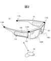
- 1 is a diagram showing an example of the external configuration of an HMD as an example of a portable information terminal according to an embodiment of the present invention.
- FIG. 2 is a diagram showing an example of a functional block configuration of an HMD.
- FIG. 2 is a functional block diagram of an HMD as a portable information terminal according to the present embodiment.
- FIG. 13 is a diagram showing an example of caution direction setting information for setting whether or not to display a caution direction according to the type of the caution direction.
- FIG. 11 is a diagram showing current management information on directions requiring caution.
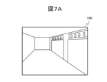
- 1A and 1B are diagrams showing examples of displays on a portable information terminal according to the embodiment.
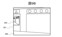
- FIG. 11 is a view showing a display example according to the second embodiment.
- FIG. 11 is a view showing a display example according to the second embodiment.
- FIG. 11 is a view showing a display example according to the second embodiment.
- FIG. 13 is a view showing a display example according to the third embodiment.
- FIG. 13 is a view showing a display example according to the third embodiment.
- 13 is a flowchart showing a process flow according to a third embodiment.
- 13 is a flowchart showing a process flow according to a fourth embodiment.
- FIG. 13 is an explanatory diagram showing importance determination item information for a cautionary direction.
- FIG. 13 is an explanatory diagram showing importance determination item information for a cautionary direction.
- FIG. 13 is a diagram showing a display example of the fourth embodiment.
- FIG. 13 is a diagram showing a display example of the fourth embodiment.
- FIG. 13 is a diagram showing an example of map information used in the fifth embodiment.
- FIG. 13 is a diagram showing an example of an image used in the fifth embodiment.
- 13 is a flowchart showing a process flow according to a sixth embodiment.
- FIG. 23 is a diagram showing the processing content of the seventh embodiment.
- the mobile information terminal is characterized in that it is equipped with a gaze detection sensor and a camera that captures the surroundings, and the processor mounted on the mobile information terminal determines the direction in which the user should direct his/her attention based on the image from the camera according to the surrounding situation, and if the user is not looking in the direction in which he/she should direct his/her attention, displays the image in that direction on the display. Therefore, since the present invention can increase the commercial value of mobile information terminals to which the present invention is applied, it is expected to contribute to 8.2 of the Sustainable Development Goals (SDGs) proposed by the United Nations (increase economic productivity through diversification, technological improvement, and innovation, mainly in industries that increase the value of goods and services and labor-intensive industries). In addition, since the burden of paying attention to the surroundings is reduced, work efficiency is improved, and contributions to energy conservation are expected, it is also expected to contribute to SDGs Goal 7 (Affordable and Clean Energy).
- SDGs Goal 7 Average and Clean Energy
- FIG. 1 is a system configuration diagram when a portable information terminal according to this embodiment is used.
- the user has at least one of the following mobile information terminals: a head mounted display (HMD) 1A and a smartphone 1B.
- the mobile information terminal may be connected to the Internet in order to refer to map information on the Internet.
- the mobile information terminal will be mainly described using the HMD 1A as an example.
- the server 3 provides map information and the like via the communication network 9.
- the server 3 may be, for example, a local server, a cloud server, an edge server, an internet service, or the like, and its form is not important.
- some of the functions of the mobile information terminal may be processed by the server 3.
- FIG. 2 is a diagram showing an example of the external configuration of an HMD as an example of a portable information terminal in this embodiment.
- the HMD 1A is equipped with a left display 102L and a right display 102R including display surfaces in a glasses-like housing 10.
- the left display 102L and the right display 102R are, for example, transparent displays, through which a real image of the outside world is transmitted to the display surfaces, and an image is superimposed on the real image.
- the housing 10 is equipped with a control device 110, a left front camera 112L, a right front camera 112R, a left rear camera 113L, a right rear camera 113R, a communication interface 141, a distance sensor 167, and a sensor group 160 including various other sensors.
- the HMD 1A may transmit and receive operation signals to and from an operating device 20 such as a remote controller via the communication interface 141.
- a user can input instructions related to the functions of the HMD 1A and move a cursor on the display screen by operating the operating device 20 with his or her hands.
- the HMD 1A may communicate with and cooperate with an external smartphone 1B, a PC, etc.
- the HMD 1A may receive AR (Augmented Reality) image data from an application on the smartphone 1B.
- the HMD1A may display virtual reality objects such as AR on the display surface.
- Figure 3 shows an example of the functional block configuration of an HMD.
- the HMD 1A includes a processor 101, a display 102, a ROM 103, a RAM 104, a storage 105, a front camera 112, a rear camera 113, a microphone 121, a speaker 122, an operation I/F 130, a communication interface 141, a wireless transmission interface 142, a wireless reception interface 143, a vibrator 150, a group of sensors 160, a distance measurement sensor 167, a gaze detection sensor 168, and a battery 170, all of which are interconnected via a bus 106.
- the rear camera 113 is a type of peripheral camera, as it captures images in a shooting direction different from the user's forward field of view.
- the control device 110 is composed of a processor 101, a ROM 103, a RAM 104, a storage 105, etc.
- the processor 101 performs processing according to control programs and application programs stored in the ROM 103 and storage 105, thereby realizing the functions of the OS, middleware, applications, and other functions.
- the display 102 includes a display drive circuit and a display surface, and displays images from the front camera 112 and rear camera 113 and virtual reality objects on the display surface based on the image data of the display information.
- ROM 103 is made up of non-volatile memory and stores programs that cannot be updated, such as the OS.
- RAM 104 is made up of volatile memory and functions as a working memory when processor 101 loads and executes programs, and as a memory for temporarily storing images captured by front camera 112 and rear camera 113, as well as sensor information output by various sensors.
- Storage 105 is a storage device, which is composed of a non-volatile storage device or the like, and stores various data and information handled by processor 101, etc.
- the front cameras 112 include a left front camera 112L and a right front camera 112R, which are disposed on the left and right front sides of the housing 10, respectively.
- the front cameras 112 capture an image by capturing an area including the area in front of the HMD 1A.
- the sensor group 160 includes various sensors for detecting the position and orientation of the HMD 1A. For example, it includes a GPS 161, a gyro sensor 162, a geomagnetic sensor 163, an acceleration sensor 164, an illuminance sensor 165, and a proximity sensor 166.
- the GPS 161 is an example of a positioning sensor.
- the distance measurement sensor 167 is a sensor that measures the distance between the HMD 1A and an object in the outside world.
- the distance measurement sensor 167 may be a TOF (Time Of Flight) type sensor, a stereo camera, or another type.
- the gaze detection sensor 168 monitors the state of the eyeball and detects the gaze direction.
- the gaze direction detected by the gaze detection sensor 168 is referred to as the main gaze direction.
- the housing 10 is equipped with a microphone 121, a speaker 122, etc.
- a left microphone and a left speaker may be provided on the left side of the housing 10
- a right microphone and a right speaker may be provided on the right side of the housing 10.
- the microphone 121 converts input voice into voice data. It may be configured as a voice input device with a voice recognition function based on the input voice from the microphone 121.
- the speaker 122 outputs audio based on the audio data.
- the communication interface 141 includes a communication processing circuit, an antenna, etc. that correspond to various predetermined communication interfaces. Examples of communication interfaces include mobile networks, Wi-Fi (registered trademark), Bluetooth (registered trademark), UWB (Ultra Wide Band), infrared, etc.
- the communication interface 141 performs wireless communication processing between other mobile information terminals and access points.
- the communication interface 141 also performs short-range communication processing with the controller 20.
- the wireless transmission interface 142 transmits a wireless signal from a radio wave source accompanied by an identification signal used for position estimation.
- the wireless signal accompanied by identification information is, for example, a UWB or Bluetooth (registered trademark) signal.
- the wireless receiving interface 143 receives the wireless signal from the radio wave source accompanied by the above-mentioned identification signal, and measures the reception strength and timing of the signal.
- the positional relationship between the mobile information terminals may be used as an aid in determining whether or not wireless power supply is possible.
- Information communication may also be performed using the wireless transmission interface 142 and the wireless reception interface 143.
- the wireless transmission interface 142 In the case of an HMD 1A that only transmits or only receives wireless signals, it is sufficient if the HMD 1A is equipped with the necessary devices.
- the operation interface 130 is a part that accepts operation inputs for the HMD 1A, such as turning the power on/off and adjusting the volume, and is composed of hardware buttons, touch sensors, etc.
- Battery 170 is a secondary battery that supplies power to each part of the HMD 1A.
- FIG. 4 is a functional block diagram of an HMD as a mobile information terminal according to this embodiment.
- the HMD 1A has, as examples of functional block configurations realized by processing by the processor 101, a data acquisition unit 101a, a caution direction detection unit 101b, a display control unit 101c, a communication control unit 101d, and an audio output control unit 101e.
- the data acquisition unit 101a acquires video information, sensor information, and audio information from the front camera 112, rear camera 113, distance measurement sensor 167, gaze detection sensor 168, and microphone 121.
- the caution direction detection unit 101b detects caution directions based on the above video information, sensor information, and audio information.
- caution-required direction means a direction to which the user should pay particular attention out of 360 degrees around the user.
- the following directions are regarded as caution-required directions, for example.
- - Direction in which the road extends including branching directions and the opposite direction of travel, using map information
- - Direction of travel - Direction of approaching object (camera, distance measurement sensor, etc.
- Direction of the source of a warning signal e.g., the source of a warning sound for entering a dangerous area using UWB (Ultra Wide Band), the siren of an emergency vehicle such as an ambulance or fire engine, the source of a warning sound for notifying the presence of a vehicle leaving a parking lot, a bicycle bell
- UWB Ultra Wide Band
- the siren of an emergency vehicle such as an ambulance or fire engine
- the source of a warning sound for notifying the presence of a vehicle leaving a parking lot
- a bicycle bell Directions requiring caution based on warning notifications (warnings from facility managers or people nearby)
- the display control unit 101c controls the display of images and virtual reality objects on the display surface of the display 102.
- the communication control unit 101d controls communication processing using the communication interface 141, such as when communicating with the server 3.
- Figure 5 shows an example of caution direction setting information that sets whether or not to display a direction depending on the type of caution direction.
- a "display flag” is associated with a "caution direction type number” and a “caution direction type” and stored. This allows for a setting in advance for each type of caution direction as to whether or not to display video and information about the caution direction. This setting may be changed by the user.
- Figure 6 shows the current management information on directions requiring caution.
- the "caution direction number,” “caution direction type number,” and “direction information” are associated with each other and stored in the RAM 104 or storage 105. It is constantly updated during display processing by the HMD 1A.
- “Caution Direction No.” is a sequence number that is assigned in the order in which caution directions are detected during the display process (from login to logout).
- “Caution direction type No.” is a number indicating the type of caution direction to which a sequence number has been assigned, and corresponds to the "Type No.” in the caution direction setting information 180 shown in FIG. 5.
- Directional information is information that indicates the direction of the cautionary direction in the world coordinate system.
- the direction indicated by “directional information” indicates the direction within the horizontal plane in the world coordinate system. For example, it is the angle measured counterclockwise from the X-axis direction. Three-dimensional directions may also be considered.
- the above-mentioned "world coordinate system” is a coordinate system fixed to the outside world. For example, north is the positive X-axis direction, the direction to the left when facing north is the positive Y-axis direction, and vertically upward is the positive Z-axis direction. Note that since directional information is managed as internal data, any appropriate coordinate system can be used.
- the "main gaze direction” mentioned above is the averaged gaze direction of the eyeball. Since the user mainly looks in the direction in which the HMD 1A is facing, the averaged direction of the HMD 1A may be used instead of the gaze direction of the eyeball.
- the averaging process can be performed by appropriately using well-known techniques such as moving average. Furthermore, it is determined that the caution direction and the user's main gaze direction match when the angular difference between the two directions is less than a predetermined display angle threshold ⁇ th.
- FIGS. 7A and 7B show examples of displays on a mobile information terminal according to this embodiment.
- 7A and 7B show examples of displays on a see-through HMD.
- FIG. 7A shows the field of view seen by a user using the HMD 1A when the user is walking along an aisle lined with shops and facing the direction the aisle extends.
- FIG. 7A only the outside world (field of view) 190 that can be seen through the glass is shown.
- Figure 7B shows the field of view of HMD 1A when the user turns their face to look at the store. Because the direction of the user's face, i.e., the user's main line of sight, has deviated from the direction in which the aisle extends, an image 192 of the direction in which the aisle extends is displayed superimposed on the field of view 191 of the outside world. Since other passersby may be walking toward them, the direction in which the aisle extends and the direction in which the user is moving is the direction in which attention should be paid (direction requiring caution). In this example, only one direction is shown as the direction requiring caution, but images of multiple directions may also be displayed.
- FIG. 8 is a flowchart showing the process flow of the first embodiment.
- the HMD 1A is an example of a mobile information terminal according to the first embodiment.
- the gaze detection sensor 168 of the HMD 1A starts detecting the main gaze direction of the user, and also starts capturing images with the front camera 112 and rear camera 113, and collecting sound from the microphone 121 (S101).
- the data acquisition unit 101a acquires video information, sensor information, and audio information.
- the caution direction detection unit 101b determines whether a caution event has occurred based on the video information from the front camera 112 and the rear camera 113, and the audio information from the microphone 121 (S102).
- the caution direction detection unit 101b detects the direction in which the caution event occurred as the caution direction (S103).
- the caution direction detection unit 101b detects the north direction based on the geomagnetic sensor 163, detects the direction in which the caution event occurred based on this north direction, and determines the caution direction. Then, in the order of detection, the caution direction detection unit 101b records the type and directional information using the angle relative to the north direction in the caution direction management information 181.
- the display control unit 101c compares the main gaze direction with the caution direction, and if it determines that the angular difference ⁇ between the main gaze direction and the caution direction is less than the display angle threshold ⁇ th (S104: No), the user can see the caution direction, so the image of the caution direction is not displayed (S105).
- the display control unit 101c determines that the angle difference ⁇ between the main line of sight direction and the direction requiring caution is equal to or greater than the display angle threshold ⁇ th (S104: Yes), it acquires an image of the direction requiring caution from the front camera 112 or the rear camera 113, reduces the image to a small screen size smaller than the full screen size of the display 102, and displays it on the display 102 (S106).
- the image of the direction requiring attention is displayed on the left display 102L or the right display 102R which is closer to the direction requiring attention. This allows the user to intuitively know whether the direction requiring attention is to the left or right of the user's front.
- the display control unit 101c can expect the same effect as above by displaying the image of the direction of caution on the left or right side closer to the direction of caution, with the left and right sides of the display surface as the center.
- the HMD 1A is a video see-through type
- the image in the direction requiring caution may be displayed, and the surrounding image displayed by the video see-through may be displayed in a faint manner. This allows the image in the direction requiring caution to stand out.
- the display control unit 101c judges whether or not it is necessary to display video of the caution direction for all caution directions listed in the caution direction management information 181. If there are any caution directions for which it has not yet determined whether they should be displayed (S107: No), the display control unit 101c returns to step S104 and judges whether or not it is necessary to display video of the caution direction for the caution direction with the next sequence number in the caution direction management information 181.
- step S107: Yes When the display control unit 101c has finished judging whether or not all of the caution directions listed in the caution direction management information 181 need to be displayed (S107: Yes), it returns to step S101 and repeats the process until an instruction to end the display of the caution direction image is received (S108: No).
- an image of the direction requiring attention can be displayed to the user to alert him/her. This makes it possible to alert the user to events requiring attention that occur in blind spots.
- this embodiment makes it possible to check images of directions other than the direction of travel where attention should be directed depending on the surrounding conditions.
- the second embodiment is an embodiment in which a variation is provided to the display mode of the image of the caution direction in the first embodiment, and the image of the caution direction is displayed by sliding from the boundary of the display surface of the display toward the center.
- Figures 9A to 9C are diagrams showing display examples according to the second embodiment.
- FIG. 9A shows the display surface 200 of the display 102 at the moment when the user's main line of sight deviates from the direction in which the road extends. From this point on, the display starts to display an image of the road's extension direction, which is a direction requiring caution.
- FIG. 9B the image 202 of the caution direction starts to be displayed from a boundary 201 on the display surface 200 of the display 102 that is close to the caution direction, and the image 202 of the caution direction is displayed by sliding it toward the center.
- FIG. 9C shows the state in which the image 202 of the caution direction is completely displayed.
- the second embodiment is an embodiment that aims to reduce the shock to the user caused by the sudden display of an image of a direction requiring caution.
- the display control unit 101c may display the image of the direction requiring caution by initially displaying the image in a light color and gradually darkening it.
- the display control unit 101c may also start by displaying the screen size of the image of the direction requiring caution at a small size and gradually increase it. In this way, by changing the color and screen size from an inconspicuous display mode to a gradually more conspicuous display mode, it is possible to prevent the user from being surprised by the sudden display of the image of the direction requiring caution.
- the third embodiment is an embodiment that provides a variation in the display mode of the video in the caution direction in the first embodiment, in which a plurality of caution images are constantly displayed, and when the main line of sight direction moves, the screen size of the caution images that are out of the main line of sight are displayed in a larger size.
- FIG. 10A shows display surface 300 when the main line of sight is facing the direction in which the passage extends forward, which is one of the directions requiring caution.
- Display surface 300 simultaneously displays image 301 facing the direction in which the passage extends forward, and image 302 extending to the rear of the passage, which is another direction requiring caution.
- the forward image is made small.
- FIG. 10B shows what happens when the user turns from this state toward the line of stores on the right.
- the image 301 in front is also displayed large.
- the display of the front may be gradually enlarged as the user's main line of sight changes.
- FIG. 11 is a flowchart showing the process flow of the third embodiment.
- steps that are the same as those in the first embodiment shown in FIG. 8 are given the same reference numerals, and duplicate explanations will be omitted.
- step S104 if it is determined in step S104 that the angular difference ⁇ between the main gaze direction and the caution direction is less than the display angle threshold ⁇ th (S104: No), the deviation of the user's main gaze direction from the caution direction is relatively small, so the caution direction is easy to see. Therefore, the image of the caution direction is displayed on a first screen size, which is a relatively small screen size (S201). Then, the process proceeds to step S107.
- step S104 determines whether the angle difference ⁇ between the main gaze direction and the caution direction is equal to or greater than the display angle threshold ⁇ th (S104: Yes). If it is determined in step S104 that the angle difference ⁇ between the main gaze direction and the caution direction is equal to or greater than the display angle threshold ⁇ th (S104: Yes), then the user's main gaze direction is relatively far from the caution direction and the user is unable to see the caution direction. Therefore, the image of the caution direction is displayed on a second screen size, which is a relatively large screen size (S202). Then, proceed to step S107.
- the image of the direction requiring caution is always displayed regardless of the user's main gaze direction, so the user can obtain information about the direction that is a blind spot.
- the screen size of the image of the direction requiring caution is displayed relatively large, so that the user can be alerted.
- the image of the direction requiring caution is constantly displayed, so it is even more preferable to determine whether the image display of the direction requiring caution interferes with the visibility of other objects, such as objects on the extension of the main line of sight.
- the image of the direction in which the user's main line of sight is facing, which requires caution, may be displayed in a small size.
- the fourth embodiment is an embodiment in which the screen size is enlarged to emphasize the image of the caution direction according to the importance of the caution event.
- Fig. 12 is a flowchart showing the flow of processing of the fourth embodiment.
- Fig. 13 is an explanatory diagram showing importance determination item information of the caution direction.
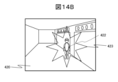
- Figs. 14A and 14B are diagrams showing a display example of the fourth embodiment.
- the caution-required direction detection unit 101b determines in step S102 that a caution-required event has occurred (S102: Yes), it detects a caution-required direction (S103) and determines the importance of the caution-required direction by referring to the importance determination item information 401 (S301).
- Information No is a number that uniquely identifies the important assessment item.
- approaching objects include humans.
- the judgment item targets objects within a specified range, for example within 15 meters.
- "vulnerable road users" in the importance judgment item information include children, elderly people, people who have difficulty walking, etc.
- Importance is a numerical value that represents the importance of each judgment item. The higher the importance number, the higher the importance.
- the direction from which an approaching object is located may be determined as a direction requiring high importance and requiring greater caution. Furthermore, even if there is an approaching object, the direction from which the object is approaching faster may be determined to be more important.
- step S104 If the caution direction detection unit 101b determines in step S104 that the angle difference ⁇ between the main gaze direction and the caution direction is equal to or greater than the display angle threshold ⁇ th (S104: Yes), the display control unit 101c highlights the image of the caution direction according to its importance, in this example, at a screen size (S302). The larger the importance value in the importance determination item information, the larger the screen size at which the display control unit 101c displays the image of the caution direction. Then, the process proceeds to step S107.
- An AR object may be used as an example of highlighting. For example, as shown in FIG. 14A, when the viewer is looking to the right in the direction in which the corridor extends, an image 411 of the direction in which the corridor extends, which is a direction requiring caution, is displayed on a display surface 410. An AR object 413 may be used to indicate an object 412 in the image 411 to which attention should be directed.
- the display of the image 411 of the caution direction may be stopped, and instead of the AR object 413 attached to the object 412 to which attention should be directed in the image 411 of the caution direction, an AR object 423 may be displayed at a position superimposed on the real image 422 of the object 412 viewed through the display 102 on the display surface 420.
- the image of the direction requiring caution is highlighted depending on the importance of the direction, so that, for example, if a dangerous object is approaching, the user can be notified of the danger as soon as possible.
- an alarm output instruction signal may be output to the audio output control unit 101e when an image of a direction requiring caution is displayed, depending on the importance of the direction requiring caution, and an alarm sound may be output from the speaker 122.
- an alarm sound may be output from the speaker 122.
- control may be performed so that no display is given even in directions requiring caution.
- the fifth embodiment is an embodiment related to grasping a direction requiring caution.
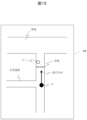
- Fig. 15 is a diagram showing an example of map information used in the fifth embodiment.
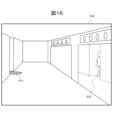
- Fig. 16 is a diagram showing an example of an image used in the fifth embodiment.
- Map information on the server 3 may be referenced to ascertain directions requiring caution around the user.
- the direction requiring caution detection unit 101b obtains map information from the server 3 and identifies passageways, road forks, and the like around the user's current location by referencing the location information of the mobile information terminal and the map information. This makes it easier to ascertain directions requiring caution.
- passage junctions, forks, and the like correspond to events requiring caution.
- a merging passage from the left of the user's traveling direction A is shown on the map 500.
- the caution direction detection unit 101b can determine that the direction to the left of the current position P on the map 500 is a caution direction based on the position information of the current position P from the GPS 161. In addition, since there is no passage to the right, it can be determined that it is not a caution direction.
- a video of a point where a roadway with heavy traffic emerges may be displayed to the user as a direction or location requiring caution.
- a video of that point may be displayed to the user as a direction or location requiring caution.
- Information regarding dangerous objects on the passageway may be obtained not only from a map, but also from the front camera 112 of the HMD 1A.
- the direction requiring caution detection unit 101b may analyze the images 510 from the front camera 112 and the rear camera 113 as shown in FIG. 16 to detect a figure 511 coming from behind a corner and a reflected image 512 in a shop window, and detect the direction requiring caution based on this.
- the acquisition of position information of the HMD 1A may be achieved by other positioning systems rather than GPS.
- the positional relationship between the terminal and feature points in the room may be grasped from images captured by the front camera 112 and rear camera 113, and distance measurement by the distance sensor 167, to acquire the terminal's position information.
- the terminal's movement information acquired by the gyro sensor 162 and acceleration sensor 164 may be used as an auxiliary means for terminal positioning. This makes it possible to provide the user with images of directions requiring caution using other positioning systems instead of GPS, even in situations where the positioning accuracy of GPS is low, such as inside a building.
- the sixth embodiment is an embodiment in which the timing of displaying the image of the caution direction is controlled so that the display does not blink.
- Fig. 17 is a flowchart showing the flow of the process of the sixth embodiment. The same steps as those in Fig. 8 are assigned the same reference numerals and the duplicated explanation will be omitted.
- step S104 If the caution direction detection unit 101b determines in step S104 that the angular difference ⁇ between the main gaze direction and the caution direction is equal to or greater than the display angle threshold ⁇ th (S104: Yes), the display control unit 101c starts measuring the elapsed time T from when the angular difference ⁇ became equal to or greater than the display angle threshold ⁇ th (S401).
- the display control unit 101c determines that the elapsed time T does not exceed the display time threshold Tth (S402: No), the process returns to step S104.
- the display time threshold Tth is a time threshold used to impart hysteresis characteristics to the condition determination that the user's main line of sight has deviated from the cautionary direction.
- the image of the caution direction is displayed, so that when the user looks at the caution direction for a short period of time, the image of the caution direction is not displayed. This prevents the image of the caution direction from switching between display and non-display and flashing, improving visibility.
- the seventh embodiment is an embodiment in which a non-wearable terminal is used as a portable information terminal.
- Fig. 18 is a diagram showing the process content of the seventh embodiment.
- the user's actual line of sight 705 is basically the main line of sight 704.
- the shooting direction 702 of the outer camera that is shooting the external image may be used as the main line of sight 704, and processing similar to that of each of the above embodiments may be performed.
- the main line of sight direction may be switched depending on the image displayed on the display 701.
- the front camera 112 may be an outer camera provided on the opposite side to the display 701, and the rear camera 113 may be an inner camera.
- multiple outer cameras may be used as the surrounding image shooting camera including the front camera 112 and the rear camera 113, or a wide-angle outer camera may be used.
- a caution direction which is the direction in which a caution event that requires attention has occurred based on the main line of sight direction, is detected from the images from these surrounding image capturing cameras, and the image of the caution direction is displayed on display 701. If a wide-angle camera is used, an image of the vicinity of the caution event may be cut out from the wide-angle image and displayed on display 701.
- a non-wearable device can provide the user with images of directions requiring caution, achieving the same effects as the above embodiments.
- the eighth embodiment is an embodiment in which an HMD equipped with a non-transmissive display is used as a portable information terminal.
- the transmissive display 102 in the HMD 1A is replaced with a non-transmissive display.
- an HMD equipped with a non-transparent display can provide images of areas requiring caution.
- each processing example may be independent programs, or multiple programs may constitute a single application program. Furthermore, the order in which each process is performed may be changed.
- each function may be realized in part or in whole by a server.
- the server may be any type that can execute functions in cooperation with other components via communication, such as a local server, cloud server, edge server, or net service.
- Information such as programs, tables, and files that realize each function may be stored in a memory, a recording device such as a hard disk or SSD (Solid State Drive), or a recording medium such as an IC card, SD card, or DVD, or may be stored in a device on a communication network.
- a recording device such as a hard disk or SSD (Solid State Drive), or a recording medium such as an IC card, SD card, or DVD, or may be stored in a device on a communication network.
- control lines and information lines shown in the diagram are those considered necessary for explanation, and do not necessarily represent all control lines and information lines on the product. In reality, it can be assumed that almost all components are interconnected.
- a portable information terminal A front camera and A peripheral camera having a shooting direction different from that of the front camera;
- the processor A gaze direction of the user detected by the gaze detection sensor is defined as a main gaze direction, and a caution direction is detected which is a direction in which a caution event that requires attention has occurred based on the main gaze direction; displaying an image of the caution-required direction on the display based on at least one of the image captured by the front camera and the image captured by the peripheral camera;
- Mobile information terminal Mobile information terminal.
- a portable information terminal A housing and A display provided on a surface of the housing; An outer camera provided on a rear surface of the housing; A processor, The processor, A direction in which a user is viewing the display is defined as a main gaze direction, and an attention-required direction is detected, the attention-required direction being a direction in which an attention-required event that requires attention has occurred based on the main gaze direction; displaying an image of the caution-required direction on the display based on the image captured by the outer camera; Mobile information terminal.
- a display control method for a mobile information terminal comprising: A step of determining a main gaze direction as a gaze direction of a user detected by a gaze detection sensor mounted on the portable information terminal, and detecting a caution direction, which is a direction in which a caution event that requires attention has occurred based on the main gaze direction; displaying the image of the caution direction on a display mounted on a portable information terminal;
- a display control method for a portable information terminal comprising:
- HMD 1B Smartphone 3: Server 9: Communication network 10: Housing 20: Controller 101: Processor 101a: Data acquisition unit 101b: Caution direction detection unit 101c: Display control unit 101d: Communication control unit 101e: Audio output control unit 102: Display 102L: Left display 102R: Right display 103: ROM 104: RAM 105: Storage 106: Bus 110: Control device 112: Front camera 112L: Left front camera 112R: Right front camera 113: Rear camera 113L: Left rear camera 113R: Right rear camera 121: Microphone 122: Speaker 130: Operation interface 141: Communication interface 142: Wireless transmission interface 143: Wireless reception interface 150: Vibrator 160: Sensor group 161: GPS 162: Gyro sensor 163: Geomagnetic sensor 164: Acceleration sensor 165: Illuminance sensor 166: Proximity sensor 167: Distance measurement sensor 168: Line of sight detection sensor 170: Battery 180: Caution direction setting information 181: Caution direction management information 191: Field of
Landscapes
- Physics & Mathematics (AREA)
- General Physics & Mathematics (AREA)
- Engineering & Computer Science (AREA)
- Optics & Photonics (AREA)
- Computer Hardware Design (AREA)
- Theoretical Computer Science (AREA)
- User Interface Of Digital Computer (AREA)
Abstract
携帯情報端末は、携帯情報端末に搭載された視線検出センサが検出したユーザの視線方向を主視線方向とし、当該主視線方向を基準として注意を喚起すべき要注意事象が発生した方向からなる要注意方向を検出し、要注意方向の映像を携帯情報端末に搭載されたディスプレイに表示する。
Description
本発明は、携帯情報端末及び携帯情報端末の表示制御方法に係り、特にユーザに周辺状況を通知するための映像表示に関する。
携帯情報端末を用いてユーザの周辺映像を表示する従来例として、特許文献1には「周辺の物体との接近をユーザが把握しやすくなるHMDであって、HMDを装着するユーザの眼前には表示部が配置されている。HMDはユーザと当該ユーザの周辺との物体との接近に応じて、表示部を制御することで表示部よりも前方をユーザに視認させる(要約抜粋)」という記載がある。
また特許文献2には「超広角度の画像から、進行方向を中心とする所定範囲の画像を進行方向画像として切り出す画像切出部と、前記進行方向画像を、当該携帯機器のディスプレイの予め定めた進行方向表示面に表示する(要約抜粋)」という記載がある。
特許文献1では、ユーザが余所見をしていて、注意を向けるべき方向が表示部よりも前方ではない場合、注意を向けるべき方向の状況を表示することができない、という課題がある。
また、特許文献2では、周囲状況に応じて進行方向以外にも注意を向けるべき方向があるという点が考慮されていない。
本発明は上記実情に鑑みてなされたものであり、ユーザが注意を向けるべき方向を見ていないときに、当該ユーザに対してその方向の映像を表示する携帯情報端末を提供することを目的とする。
上記課題を解決するために、本発明は、特許請求の範囲に記載の構成を備える。
本発明によれば、ユーザが注意を向けるべき方向を見ていないときに、当該ユーザに対してその方向の映像を表示する携帯情報端末を提供することができる。なお、上記した以外の課題、構成及び効果は、以下の実施形態の説明により明らかにされる。
以下、図面を参照しながら、本発明の実施形態について説明する。全図を通じて同一の構成には同一の符号を付し、重複説明を省略する。
本実施形態に係る携帯情報端末は、視線検出センサと周囲を撮影するカメラとを備え、携帯情報端末に搭載されたプロセッサが、カメラの映像を基に周囲状況に応じてユーザが注意を向けるべき方向を決定し、ユーザが注意を向けるべき方向を見ていない場合、その方向の映像をディスプレイに表示する点に特徴がある。よって本発明は、本発明を適用した携帯情報端末の商品価値を高めることができることから、国連の提唱する持続可能な開発目標(SDGs:Sustainable Development Goals)の8.2(商品やサービスの価値をより高める産業や、労働集約型の産業を中心に、多様化、技術の向上、イノベーションを通じて、経済の生産性をあげる)に貢献することが期待できる。また、周辺注意の負担が軽減し、作業の効率化が図られ、省エネへの貢献が期待できることからSDGsの目標7(エネルギーをみんなにそしてクリーンに)への貢献も期待できる。
[第1実施形態]
図1は、本実施形態における携帯情報端末の使用時のシステム構成図である。
図1は、本実施形態における携帯情報端末の使用時のシステム構成図である。
図1において、ユーザは携帯情報端末としては、例えば、HMD(Head Mounted Display)1A、スマートフォン1B、の少なくとも1つを持つ。ネット上の地図情報等を参照する場合に対応するために、携帯情報端末は、インターネットに接続されていてもよい。以下では、携帯情報端末として主にHMD1Aを例示して説明する。
サーバ3は、通信網9を介して、地図情報等の提供を行う。サーバ3は例えば、ローカルサーバ、クラウドサーバ、エッジサーバ、ネットサービス等であり、その形態は問わない。また、携帯情報端末の機能の一部をサーバ3で処理してもよい。
[ハード構成等の説明]
図2は、本実施形態における携帯情報端末の一例としてのHMDの外観構成例を示す図である。
図2は、本実施形態における携帯情報端末の一例としてのHMDの外観構成例を示す図である。
図2において、HMD1Aは、眼鏡状の筐体10に、表示面を含む左ディスプレイ102L、右ディスプレイ102Rを備える。左ディスプレイ102L、右ディスプレイ102Rは、例えば透過型ディスプレイであり、表示面には外界の実像が透過され、その実像上に画像が重畳表示される。筐体10には、制御装置110、左前方カメラ112L、右前方カメラ112R、左後方カメラ113L、右後方カメラ113R、通信インタフェース141、測距センサ167、他の各種センサを含むセンサ群160等が実装されている。
HMD1Aは、通信インタフェース141を介してリモートコントローラ等の操作器20との間で操作信号を送受信してもよい。ユーザは、手で操作器20を操作することで、HMD1Aの機能に関する指示入力や表示面でのカーソル移動等ができる。HMD1Aは、外部のスマートフォン1BやPC等と通信して連携を行ってもよい。例えば、HMD1Aは、スマートフォン1BのアプリケーションからAR(拡張現実:Augmented Reality)の画像データを受信してもよい。
HMD1Aは、AR等の仮想現実オブジェクトを表示面に表示させてもよい。
図3は、HMDの機能ブロック構成例である。
HMD1Aは、プロセッサ101、ディスプレイ102、ROM103、RAM104、ストレージ105、前方カメラ112、後方カメラ113、マイク121、スピーカ122、操作I/F130、通信インタフェース141、無線送信インタフェース142、無線受信インタフェース143、バイブレータ150、センサ群160、測距センサ167、視線検出センサ168、及びバッテリ170を備え、これらがバス106を通じて相互に接続されている。後方カメラ113はユーザの前方視界とは異なる撮影方向の映像を撮像するので周辺カメラの一態様である。
制御装置110は、プロセッサ101、ROM103、RAM104、ストレージ105等で構成される。
プロセッサ101は、ROM103やストレージ105に格納された制御プログラムやアプリケーションプログラムに従った処理を実行することにより、OS、ミドルウェア、アプリケーション等の機能や他の機能を実現する。
ディスプレイ102は、表示駆動回路や表示面を含み、表示情報の画像データに基づいて、表示面に前方カメラ112及び後方カメラ113の映像や仮想現実オブジェクトを表示する。
ROM103は、不揮発性メモリにより構成され、更新不可とするプログラム、例えばOSが記憶される。
RAM104は揮発性メモリにより構成され、プロセッサ101がプログラムをロードして実行する際のワークメモリとして、また前方カメラ112や後方カメラ113が撮像した映像、また各種センサが出力したセンサ情報を一時的に記憶するメモリとして機能する。
ストレージ105は記憶装置であって、不揮発性記憶装置等で構成され、プロセッサ101等が扱う各種のデータや情報を記憶する。
前方カメラ112は、左前方カメラ112L及び右前方カメラ112Rを含み、筐体10の左右前側にそれぞれ配置される。前方カメラ112は、HMD1Aの前方を含む範囲を撮影して画像を取得する。
後方カメラ113は、左後方カメラ113L及び右後方カメラ113Rを含み、筐体10の左右後側にそれぞれ配置される。後方カメラ113は、HMD1Aの後方を含む範囲を撮影して画像を取得する。
センサ群160は、HMD1Aの位置及び向きの状態を検出するための各種センサを含む。例えば、GPS161、ジャイロセンサ162、地磁気センサ163、加速度センサ164、照度センサ165、及び近接センサ166を含む。GPS161は測位センサの一例である。
測距センサ167は、HMD1Aと外界の物体との距離を測定するセンサである。測距センサ167は、TOF(Time Of Flight)方式のセンサを用いてもよいし、ステレオカメラや他の方式を用いてもよい。
視線検出センサ168は、眼球の状態をモニタし、視線方向を検出する。本明細書では視線検出センサ168が検出した視線方向を主視線方向という。
筐体10には、マイク121、スピーカ122等を備える。ステレオマイク、ステレオスピーカの場合は筐体10の左に左マイク、左スピーカを、筐体10の右に右マイク、右スピーカを備えてもよい。
マイク121は、入力音声を音声データに変換する。マイク121からの入力音声に基づいて音声認識機能を備える音声入力装置として構成してもよい。
スピーカ122は、音声データに基づいて音声を出力する。
通信インタフェース141は、所定の各種の通信インタフェースに対応する通信処理回路やアンテナ等を含む。通信インタフェースの例は、モバイル網、Wi-Fi(登録商標)、Bluetooth(登録商標)、UWB(Ultra Wide Band)、赤外線等が挙げられる。通信インタフェース141は、他の携帯情報端末やアクセスポイントとの間での無線通信処理等を行う。また、通信インタフェース141は、操作器20との近距離通信処理も行う。
無線送信インタフェース142は、位置推定に用いる識別信号を伴った電波源の無線信号を送信する。ここで、識別情報を伴った無線信号とは、例えば、UWB、Bluetooth(登録商標)等の信号である。
無線受信インタフェース143は、上記の識別信号を伴った電波源の無線信号を受信し、受信強度や信号のタイミング等を測定する。なお、携帯情報端末間の位置関係を無線給電の可否の判断の補助としてもよい。
また、無線送信インタフェース142と無線受信インタフェース143を使用して、情報通信を行ってもよい。また、無線信号の送信のみ、あるいは受信のみ行うHMD1Aの場合は、必要なデバイスを備えていればよい。
操作インタフェース130は、HMD1Aに対する操作入力、例えば電源オン/オフや音量調整等を受け付ける部分であり、ハードウェアボタンやタッチセンサ等で構成される。
バッテリ170は二次バッテリであって、HMD1Aの各部に電力を供給する。
図4は、本実施形態に係る携帯情報端末としてのHMDの機能ブロック図である。
HMD1Aはプロセッサ101による処理によって実現される機能ブロックの構成例として、データ取得部101a、要注意方向検出部101b、表示制御部101c、通信制御部101d、及び音声出力制御部101eを有する。
データ取得部101aは、前方カメラ112、後方カメラ113、測距センサ167、視線検出センサ168、マイク121から映像情報、センサ情報、音声情報を取得する。
要注意方向検出部101bは、上記映像情報、センサ情報、音声情報に基づいて要注意方向を検出する。
ここでいう「要注意方向」とは、ユーザの周囲360度のうち、ユーザが注意を特に向けるべき方向を意味する。本実施形態では、例えば下記の方向を要注意方向とする。
・道が伸びる方向(分岐方向、進行方向の逆も含む、地図情報利用)
・進行方向
・何か物体が接近してくる方向(カメラ、測距センサ等。ガラス等の反射面、影も利用)
・警告信号の発生源方向(例:UWB(Ultra Wide Band)を用いた危険領域への立ち入り警告音の発生源、救急車や消防車等の緊急車両のサイレン、駐車場からの出庫車の存在を伝える警告音の発生源、自転車のベル)
・警告通知(施設管理者や、近傍の人からの警告)に基づく要注意方向
・道が伸びる方向(分岐方向、進行方向の逆も含む、地図情報利用)
・進行方向
・何か物体が接近してくる方向(カメラ、測距センサ等。ガラス等の反射面、影も利用)
・警告信号の発生源方向(例:UWB(Ultra Wide Band)を用いた危険領域への立ち入り警告音の発生源、救急車や消防車等の緊急車両のサイレン、駐車場からの出庫車の存在を伝える警告音の発生源、自転車のベル)
・警告通知(施設管理者や、近傍の人からの警告)に基づく要注意方向
表示制御部101cは、ディスプレイ102の表示面への映像及び仮想現実オブジェクトの表示を制御する。
通信制御部101dは、サーバ3との通信の際等に、通信インタフェース141を用いた通信処理を制御する。
図5は、要注意方向の種別に応じた表示の有無を設定する要注意方向設定情報の例を示す図である。
要注意方向設定情報180では、「要注意方向種別No.」「要注意方向の種別」に「表示フラグ」を関連付けて記憶する。これにより、要注意方向の種別毎に、当該要注意方向の映像や情報を表示するかどうか予め設定しておくことができる。この設定は、ユーザにより変更されてもよい。
図6は、その時々の要注意方向管理情報を示す図である。
要注意方向管理情報181では、「要注意方向No.」、「要注意方向種別No.」、「方向情報」を関係づけてRAM104又はストレージ105に記憶される。HMD1Aによる表示処理中に常に更新される。
「要注意方向No.」は、表示処理中(ログインからログアウトまで)に要注意方向が検出されるとその検出順に振られるシーケンス番号である。
「要注意方向種別No.」は、シーケンス番号が振られた要注意方向の種別を示す番号であり、図5に示した要注意方向設定情報180における「種別No.」に相当する番号である。
「方向情報」は、要注意方向の世界座標系における方向を示す情報である。「方向情報」が示す方向は、世界座標系における水平面内での方向を示す。例えば、X軸方向から左回りに測った角度等である。また3次元的な方向を考えてもよい。上記「世界座標系」とは、外界に固定された座標系である。例えば、北がX軸正方向で、北を向いた時の左手方向がY軸正方向、鉛直上向きがZ軸正方向である。なお、方向情報の管理は内部データであるので、適宜適当な座標系を用いればよい。
図6で表示対象となる要注意方向のみ管理している。この要注意方向管理情報181で把握した要注意方向がユーザの主視線方向から外れている場合は、HMD1Aはディスプレイ102にその方向の映像を表示する。
上記「主視線方向」とは、平均化した眼球の視線方向である。ユーザは、主としてHMD1Aが向いている方向をみているので、眼球の視線方向の代わりに、平均化したHMD1Aの向きを用いてもよい。平均化の処理は移動平均等、周知の技術を適宜用いればよい。また、要注意方向とユーザの主視線方向の一致の判断は、両方向の角度差がある予め定めた表示角度閾値θth未満になった場合とする。
図7A、図7Bは、本実施形態に係る携帯情報端末における表示例を示す。図7A、図7Bでは、透過型HMDの表示例を示す。
図7Aは、店舗が並ぶ通路にて、ユーザが通路沿いに歩行し、通路が延びる方向を向いている場合のHMD1Aにおけるユーザが視認する視野を示す。この図7Aでは、透過して見える外界の様子(視界)190のみを示している。
図7Bは、ユーザが顔の向きを変えて店舗を見ている時のHMD1Aの視野を表す。ユーザの顔の向き、すなわちユーザの主視線方向が、通路が延びる方向から外れたために、通路が延びる方向の映像192を外界の視界191に重畳させて表示する。他の通行人が歩いてくることもあるので、通路の延びる方向でありかつユーザの進行方向でもある方向がここでの注意を向けるべき方向(要注意方向)である。この例では、要注意方向として1方向のみ示しているが、複数の方向の映像を表示してもよい。
図8は、第1実施形態の処理の流れを示すフローチャートである。HMD1Aは、第1実施形態に係る携帯情報端末の一例である。
ユーザがHMD1Aを装着し、要注意方向の表示制御を開始すると、HMD1Aの視線検出センサ168はユーザの主視線方向の検出を開始すると共に、前方カメラ112及び後方カメラ113の撮像、マイク121からの集音を開始する(S101)。データ取得部101aは、映像情報、センサ情報及び音声情報を取得する。
要注意方向検出部101bは、前方カメラ112及び後方カメラ113の其々からの映像情報、マイク121からの音声情報を基に、要注意事象が発生したかを判断する(S102)。
要注意事象が発生したと判断すると(S102:Yes)、要注意方向検出部101bは、要注意事象の発生方向を要注意方向として検出する(S103)。世界座標系を基準とする場合は、要注意方向検出部101bは、地磁気センサ163を基に北方向を検出し、この北方向を基準とする要注意事象の発生方向を検出して要注意方向を定める。そして、検出した順に要注意方向管理情報181にその種別と北向きに対する角度を用いた方向情報を記録する。
表示制御部101cは主視線方向と要注意方向とを比較し、主視線方向と要注意方向との角度差Δθが表示角度閾値θth未満と判断すると(S104:No)、ユーザは要注意方向を視認できるので要注意方向の映像は表示しない(S105)。
表示制御部101cは、主視線方向と要注意方向との角度差Δθが表示角度閾値θth以上と判断すると(S104:Yes)、前方カメラ112又は後方カメラ113から要注意方向の映像を取得し、当該映像をディスプレイ102の全画面サイズよりは小さい小画面サイズに縮小してディスプレイ102に表示する(S106)。
その際、左ディスプレイ102Lと右ディスプレイ102Rとがある場合は、要注意方向により近い側の左ディスプレイ102L又は右ディスプレイ102Rに要注意方向の映像を表示する。これにより、ユーザは直感的に要注意方向がユーザの正面を基準として左右どちらにあるかを把握できる。
ディスプレイ102が一表示面から構成される場合、あるいは、左ディスプレイ102Lと右ディスプレイ102Rの表示を統合して3D表示を行う場合は、表示制御部101cは、表示面の左右方向を中心として左側又は右側のより要注意方向に近い側に要注意方向の映像を表示すると上記と同様の効果が期待できる。
このように、要注意方向の映像の表示位置は、ディスプレイ102の表示面内において要注意方向に近い領域とすることにより、ユーザにとって要注意方向が直観的に分かり易くなる。
また、HMD1Aがビデオシースルー型である場合、要注意方向の映像を表示すると共に、ビデオシースルーで表示している周囲映像を薄く表示するようにしてもよい。これにより、要注意方向の映像を際立たせることができる。
表示制御部101cは、要注意方向管理情報181に記載された全ての要注意方向について要注意方向の映像の表示の要否を判断する。表示の要否を判断していない要注意方向が残っている場合は(S107:No)、表示制御部101cはステップS104へ戻り、要注意方向管理情報181における次のシーケンス番号の要注意方向について要注意方向の映像の要否を判断する。
表示制御部101cは、要注意方向管理情報181に記載された全ての要注意方向について表示の要否の判断が終了すると(S107:Yes)、要注意方向映像の表示の終了指示があるまでは(S108:No)、ステップS101へ戻り処理を繰り返す。
要注意方向映像の表示の終了指示がされると(S108:Yes)、処理を終了する。
本実施形態によれば、携帯情報端末を装着したユーザが余所見をしたり、ユーザが主に見ている主視線方向とは異なる方向に注意をすべき事象が発生した場合は、ユーザに要注意方向の映像を表示して注意を促すことができる。これにより、死角で発生した要注意事象に対して、ユーザの注意喚起が行える。
また本実施形態によれば、周囲状況に応じて進行方向以外の注意を向けるべき方向の映像を確認することができる。
<第2実施形態>
第2実施形態は、第1実施形態において要注意方向の映像の表示態様にバリエーションを設ける態様であって、要注意方向の映像をディスプレイの表示面の境界から中央方向に向けて滑り込ませて表示させる実施形態である。図9Aから図9Cは、第2実施形態に係る表示例を示す図である。
第2実施形態は、第1実施形態において要注意方向の映像の表示態様にバリエーションを設ける態様であって、要注意方向の映像をディスプレイの表示面の境界から中央方向に向けて滑り込ませて表示させる実施形態である。図9Aから図9Cは、第2実施形態に係る表示例を示す図である。
図9Aは、ユーザの主視線方向が道路の延伸方向から外れた瞬間の状態におけるディスプレイ102の表示面200を示す。この状態の時点から要注意方向である道路の延伸方向の映像の表示を開始する。
その際、図9Bに示すようにディスプレイ102の表示面200のうち、要注意方向に近い境界201から要注意方向の映像202の表示を開始し、要注意方向の映像202を中心方向に滑り込ませて表示する。図9Cは、要注意方向の映像202が完全に表示された状態を示す。
なお、要注意方向の映像202は視界の中心に配置されるとユーザが見たい場所が見づらくなるので主視線方向と要注意方向の映像202が重ならない位置に配置することが望ましい。
図9A、図9B、図9Cに示すように、ディスプレイのうち要注意方向に近い境界から要注意方向の映像が滑り込ませて表示することで、要注意方向の映像がいきなり表示されなくなり、要注意方向の映像が急に表示されてユーザを驚かせないようにすることができる。
第2実施形態は、要注意方向の映像が急に表示されることによるユーザのショックを緩和することを目的する実施形態であるが、上記の構成に代えて、例えば、表示制御部101cが要注意方向の映像の色彩を始めは薄く、徐々に濃く表示して要注意方向の映像を表示してもよい。
また、表示制御部101cは、要注意方向の映像の画面サイズを小さい表示から始めて徐々に大きくしてもよい。このように色彩や画面サイズを目立たない表示態様から徐々に目立させる表示態様に変更することで、要注意方向の映像が急に表示されてユーザを驚かせないようにしてもよい。
<第3実施形態>
第3実施形態は、第1実施形態において要注意方向の映像の表示態様にバリエーションを設ける態様であって、複数の要注意画像を常時表示しておき、主視線方向が移動すると主視線方向からから外れた要注意画像の画面サイズを大きく表示する実施形態である。図10A、図10Bは、第3実施形態に係る表示例を示す図である。
第3実施形態は、第1実施形態において要注意方向の映像の表示態様にバリエーションを設ける態様であって、複数の要注意画像を常時表示しておき、主視線方向が移動すると主視線方向からから外れた要注意画像の画面サイズを大きく表示する実施形態である。図10A、図10Bは、第3実施形態に係る表示例を示す図である。
図10Aは、主視線方向が要注意方向の一つである、前方への通路の延伸方向に向いている時の表示面300である。表示面300には、前方への通路の延伸方向に向いている映像301と、もう一つの要注意方向である、通路の後方に延びる映像302も同時に表示している。前方の映像は小さくしてある。
この状態から、ユーザが右側に並ぶ店舗の方を向いた時の状態を示したものが図10Bである。この場合、前方の映像301も大きな表示としている。前方の表示はユーザの主視線方向の変化に伴って、徐々に大きくしてもよい。
図11は、第3実施形態の処理の流れを示すフローチャートである。図11において図8に示す第1実施形態と同一のステップには同一の符号を付し重複説明を省略する。
第3実施形態では、ステップS104において主視線方向とその要注意方向の角度差Δθが表示角度閾値θth未満であると判断されると(S104:No)、ユーザの主視線方向の要注意方向からのずれは相対的に小さいので、要注意方向も見やすい。よってその要注意方向の映像を相対的に小さい画面サイズである第1の画面サイズで表示する(S201)。その後ステップS107へ進む。
一方、ステップS104において主視線方向とその要注意方向の角度差Δθが表示角度閾値θth以上と判断されると(S104:Yes)、ユーザの主視線方向が要注意方向から相対的に大きくずれているのでユーザは要注意方向が見えていない。よってその要注意方向の映像を相対的に大きい画面サイズである第2の画面サイズで表示する(S202)。その後ステップS107へ進む。
本実施形態によればユーザの主視線方向に関わらず要注意方向の映像は常に表示されるので、ユーザにとって死角となる方向の情報を得ることができる。そして、主視線方向と要注意方向の角度差が表示角度閾値以上となると要注意方向の映像の画面サイズを相対的に大きく表示するので注意を喚起することができる。
本実施形態では要注意方向の映像を常時表示しておくので、要注意方向の映像表示が他のもの、例えば主視線方向の延長上の物体の視認の妨害にならないかを判断すると更に好ましい。
また、ユーザの主視線方向が向いている要注意方向の映像は小さく表示していてもよい。
<第4実施形態>
第4実施形態は、要注意事象の重要性に従って要注意方向の映像を強調するために画面サイズを大きく表示する実施形態である。以下、図12から図14Bを参照して本実施形態について説明する。図12は、第4実施形態の処理の流れを示すフローチャートである。図13は、要注意方向の重要度判定項目情報を示す説明図である。図14A、図14Bは、第4実施形態の表示例を示す図である。
第4実施形態は、要注意事象の重要性に従って要注意方向の映像を強調するために画面サイズを大きく表示する実施形態である。以下、図12から図14Bを参照して本実施形態について説明する。図12は、第4実施形態の処理の流れを示すフローチャートである。図13は、要注意方向の重要度判定項目情報を示す説明図である。図14A、図14Bは、第4実施形態の表示例を示す図である。
図12において、図8と同一のステップには同一の符号を付し、重複説明を省略する。
要注意方向検出部101bは、ステップS102で要注意事象が発生したと判定すると(S102:Yes)、要注意方向を検出し(S103)、重要度判定項目情報401を参照して要注意方向の重要度を判定する(S301)。
図13に示す重要度判定項目情報401には、「項目No.」、「判定内容」、「重要度」が関連付けて記憶される。
「項目No.」は重要判定項目を固有に示す番号である。
「判定内容」は、重要度判定項目の詳細を示す。
重要度判定項目には、近づいてくる物体には人間も含まれる。また判定項目は、所定の範囲内例えば15m以内の物体を対象とする。なお重要度判定項目情報における「交通弱者」とは、子供、高齢者、歩行に困難が伴う人等である。
「重要度」は、各判定項目の重要度を数値化した値である。重要度の数値が大きいほど重要度が高い。
重要度を判定する項目としては、例えば、近づいてくる物体がある方向をより高い注意が必要な重要度が高い要注意方向と定めてもよい。更に、近づいてくる物体がある場合でも、より速く近づいてくる物体がある方向をより重要度を高く決定してもよい。
要注意方向検出部101bは、ステップS104において主視線方向とその要注意方向の角度差Δθが表示角度閾値θth以上と判断すると(S104:Yes)、表示制御部101cは、その要注意方向の映像を重要度に応じた強調表示、本例では画面サイズで表示する(S302)。表示制御部101cは、重要度判定項目情報において重要度の数値が大きいほど大きな画面サイズで要注意方向の映像を表示する。その後、ステップS107へ進む。
強調表示例としてARオブジェクトを用いてもよい。例えば、図14Aに示すように、通路の延伸方向に対して右を視認している状態の表示面410には、要注意方向である通路の延伸方向の映像411が表示されるが、映像411において注意を向けるべき対象412を、ARオブジェクト413にて指示してもよい。
そして、図14Bに示すように、ユーザが注意を向ける方向に主視線方向を向けた時に要注意方向の映像411の表示をやめると共に、要注意方向の映像411で注意を向けるべき対象412に対して付けたARオブジェクト413の代わりに、表示面420におけるディスプレイ102を透過して視認した対象412の実像422に重なる位置にARオブジェクト423を表示してもよい。
本実施形態によれば、要注意方向の重要性に応じて要注意方向の映像を強調表示するので、例えば危険物が接近している場合にユーザにいち早くその危険性を知らせることができる。
本実施形態の変形例として、要注意方向の重要性に応じて要注意方向の映像の表示時に音声出力制御部101eに対してアラームの出力指示信号を出力しスピーカ122からアラーム音を出力してもよい。その際、アラーム音の音像定位は要注意方向に設定すると注意を向ける方向がすぐに分かり、より効果的である。
また変形例として安全な状況である場合、要注意方向であっても表示を行わないという制御を行ってもよい。
<第5実施形態>
第5実施形態は、要注意方向の把握に関する実施形態である。図15は、第5実施形態で用いられる地図情報の例を示す図である。図16は、第5実施形態で用いられる映像例を示す図である。
第5実施形態は、要注意方向の把握に関する実施形態である。図15は、第5実施形態で用いられる地図情報の例を示す図である。図16は、第5実施形態で用いられる映像例を示す図である。
ユーザ周囲の要注意方向を把握するために、サーバ3上の地図情報を参照してもよい。要注意方向検出部101bは、サーバ3から地図情報を取得し、携帯情報端末の位置情報と地図情報とを参照することにより、ユーザの現在位置周辺の通路、道路の分岐点等を把握する。これにより、要注意方向の把握が容易となる。本実施形態では、通路の合流点、分岐点などが要注意事象に相当する。
図15の例では、地図500にユーザの進行方向Aに対して左方向からの合流通路が記載されている。要注意方向検出部101bは、GPS161からの現在位置Pの位置情報に基づいて地図500において現在位置Pの左方向を要注意方向と判定できる。また右方向は通路がないことから要注意方向ではないと判定できる。
地図情報による注意喚起の変形例として、進行方向における構造的な危険を知らせるものでもよい。例えば、交通量の多い車道に出るポイントを要注意方向あるいは要注意地点としてユーザに対してそのポイントの映像を表示してもよい。更に、穴であるとか段差であるとか、通路上の危険物等の位置が把握できるのであれば、同じくそのポイントを要注意方向あるいは要注意地点としてユーザに対してそのポイントの映像を表示してもよい。通路上の危険物に関する情報は、地図から取得する以外でもHMD1Aの前方カメラ112により取得してもよい。
また、要注意方向の検出の別例として、要注意方向検出部101bは、図16に示すように前方カメラ112及び後方カメラ113の映像510を解析して、曲がり角の陰から伸びてくる人影511及びショーウィンドウの反射像512を検出し、これを基に要注意方向を検出してもよい。
これにより、前方カメラ112及び後方カメラ113に直接映らない物体の存在を検出して要注意方向を検出することができ、ユーザ端末からの死角をカバーすることができる。
なお、HMD1Aの位置情報の取得は、GPSによらず、他の測位システムによってもよい。例えば、部屋内の特徴点と端末との位置関係を、前方カメラ112及び後方カメラ113による撮像画像、及び測距センサ167による距離測定により把握することにより、端末の位置情報を取得してもよい。更に、ジャイロセンサ162及び加速度センサ164により取得する端末の移動情報を端末測位の補助手段として使用してもよい。これにより、建物の内部のようにGPSでは測位の精度が低い状況でもGPSに代わる他の測位システムを用いてユーザに要注意方向の映像を提供できる。
<第6実施形態>
第6実施形態は、要注意方向の映像を表示するタイミングを表示が点滅しないように制御する実施形態である。図17は、第6実施形態の処理の流れを示すフローチャートである。図8と同一のステップには同一の符号を付し重複説明を省略する。
第6実施形態は、要注意方向の映像を表示するタイミングを表示が点滅しないように制御する実施形態である。図17は、第6実施形態の処理の流れを示すフローチャートである。図8と同一のステップには同一の符号を付し重複説明を省略する。
要注意方向検出部101bがステップS104において主視線方向とその要注意方向の角度差Δθが表示角度閾値θth以上と判断すると(S104:Yes)、表示制御部101cは、角度差Δθが表示角度閾値θth以上となってからの経過時間Tの計測を開始する(S401)。
表示制御部101cは経過時間Tが表示時間閾値Tthを超えていないと判断すると(S402:No)ステップS104へ戻る。表示時間閾値Tthは、要注意方向からユーザの主視線方向が外れたという条件判定にヒステリシス特性を持たせるために用いる時間閾値である。
経過時間Tが表示時間閾値Tth以上であると判断すると(S402:Yes)その要注意方向の映像を表示する(S106)。
本実施形態によれば、表示時間閾値Tth以上継続して主視線方向と要注意方向の角度差Δθが表示角度閾値θth以上となると要注意方向の映像を表示するので、ユーザが短時間要注意方向を見たときには要注意方向の映像が表示されない。これにより、要注意方向の映像が表示又は非表示に切り替わり点滅することを防止し、視認性を向上させることができる。
<第7実施形態>
第7実施形態は、携帯情報端末として非ウェアラブル端末を用いる実施形態である。図18は、第7実施形態の処理内容を示す図である。
第7実施形態は、携帯情報端末として非ウェアラブル端末を用いる実施形態である。図18は、第7実施形態の処理内容を示す図である。
図18に示すように非ウェアラブル端末として、スマートフォン1Bやタブレットのように筐体表面にディスプレイ701、背面にアウトカメラを有し、ユーザが把持して用いる携帯情報端末を用いる場合も、基本的にユーザの実視線方向705を主視線方向704とする。但し、ディスプレイ701に外界映像を表示している場合は、ユーザの実視線方向705を用いる代わりに、当該外界映像を撮影しているアウトカメラの撮影方向702を主視線方向704として用い、上記各実施形態と同様の処理を行ってもよい。あるいは、ディスプレイ701の表示映像により、主視線方向を切替えてもよい。非ウェアラブル端末の場合は、前方カメラ112はディスプレイ701と反対側に備えられたアウトカメラとすればよく、後方カメラ113はインカメラとすればよい。非ウェアラブル端末の場合も、できるだけ広い範囲の要注意方向を撮影することが望ましいため、前方カメラ112と後方カメラ113を含む周囲映像撮影カメラとして、アウトカメラを複数用いたり、広角のアウトカメラを用いてもよい。主視線方向を基準として注意を喚起すべき要注意事象が発生した方向からなる要注意方向をこれらの周囲映像撮影カメラの映像から検出し、要注意方向の映像をディスプレイ701に表示する。広角カメラを用いる場合は、広角映像から要注意事象近傍の映像を切り出してディプレイ701に表示してもよい。
本実施形態によれば、非ウェアラブル端末であってもユーザに対して要注意方向の映像を提供し、上記各実施形態と同様の作用効果を奏することができる。
<第8実施形態>
第8実施形態は、携帯情報端末として非透過型ディスプレイを搭載したHMDを用いる実施形態である。本実施形態では、上記HMD1Aにおける透過型のディスプレイ102が非透過型ディスプレイに代わる。
第8実施形態は、携帯情報端末として非透過型ディスプレイを搭載したHMDを用いる実施形態である。本実施形態では、上記HMD1Aにおける透過型のディスプレイ102が非透過型ディスプレイに代わる。
非透過型のHMDでビデオシースルーにして外界を見る場合は、透過型のHMDに準じた制御を行う。その際、非透過型のHMDの場合は、通常の状態で外界が見えないので、主視線方向は定義できない。この場合、要注意方向が発生した時点でその方向の映像を表示する。また、通路があっても、その通路を移動する行動をとらない限り、要注意方向とは見做さなくてもよい。
本実施形態によれば非透過型ディスプレイを搭載したHMDでも要注意方向の映像を提供することができる。
以上、本発明の実施形態について説明したが、言うまでもなく、本発明の技術を実現する構成は上記実施形態に限られるものではなく、様々な変形例が考えられる。例えば、前述した実施の形態は、本発明を分かり易く説明するために詳細に説明したものであり、必ずしも説明した全ての構成を備えるものに限定されるものではない。また、ある実施形態の構成の一部を他の実施形態の構成と置き換えることが可能であり、また、ある実施形態の構成に他の実施形態の構成を加えることも可能である。これらは全て本発明の範疇に属するものである。また、文中や図中に現れる数値やメッセージ等もあくまでも一例であり、異なるものを用いても本発明の効果を損なうことはない。
また、各処理例で説明したプログラムは、それぞれ独立したプログラムでもよく、複数のプログラムが一つのアプリケーションプログラムを構成していてもよい。また、各処理を行う順番を入れ替えて実行するようにしてもよい。
前述した本発明の機能等は、それらの一部又は全部を、例えば集積回路で設計する等によりハードウェアで実現してもよい。また、マイクロプロセッサユニット、CPU等がそれぞれの機能等を実現する動作プログラムを解釈して実行することによりソフトウェアで実現してもよい。また、ソフトウェアの実装範囲を限定するものでなく、ハードウェアとソフトウェアを併用してもよい。また、各機能の一部又は全部をサーバで実現してもよい。なお、サーバは、通信を介して他の構成部分と連携し機能の実行ができればよく、例えば、ローカルサーバ、クラウドサーバ、エッジサーバ、ネットサービス等であり、その形態は問わない。各機能を実現するプログラム、テーブル、ファイル等の情報は、メモリや、ハードディスク、SSD(Solid State Drive)等の記録装置、又は、ICカード、SDカード、DVD等の記録媒体に格納されてもよいし、通信網上の装置に格納されてもよい。
また、図中に示した制御線や情報線は説明上必要と考えられるものを示しており、必ずしも製品上の全ての制御線や情報線を示しているとは限らない。実際には殆ど全ての構成が相互に接続されていると考えてもよい。
前記実施の形態は、以下の形態を含む。
(付記1)
携帯情報端末であって、
前方カメラと、
前方カメラとは異なる撮影方向を有する周辺カメラと、
ディスプレイと、
ユーザの視線方向を検出する視線検出センサと、
プロセッサと、を備え、
前記プロセッサは、
前記視線検出センサが検出した前記ユーザの視線方向を主視線方向とし、当該主視線方向を基準として注意を喚起すべき要注意事象が発生した方向からなる要注意方向を検出し、
前記前方カメラが撮像した映像及び前記周辺カメラが撮像した映像の少なくとも一つ以上に基づいて、前記要注意方向の映像を前記ディスプレイに表示する、
携帯情報端末。
携帯情報端末であって、
前方カメラと、
前方カメラとは異なる撮影方向を有する周辺カメラと、
ディスプレイと、
ユーザの視線方向を検出する視線検出センサと、
プロセッサと、を備え、
前記プロセッサは、
前記視線検出センサが検出した前記ユーザの視線方向を主視線方向とし、当該主視線方向を基準として注意を喚起すべき要注意事象が発生した方向からなる要注意方向を検出し、
前記前方カメラが撮像した映像及び前記周辺カメラが撮像した映像の少なくとも一つ以上に基づいて、前記要注意方向の映像を前記ディスプレイに表示する、
携帯情報端末。
(付記2)
携帯情報端末であって、
筐体と、
前記筐体の表面に備えられたディスプレイと、
前記筐体の裏面に備えられたアウトカメラと、
プロセッサと、を備え、
前記プロセッサは、
ユーザが前記ディスプレイを視認している方向を主視線方向とし、当該主視線方向を基準として注意を喚起すべき要注意事象が発生した方向からなる要注意方向を検出し、
前記アウトカメラが撮像した映像に基づいて、前記要注意方向の映像を前記ディスプレイに表示する、
携帯情報端末。
携帯情報端末であって、
筐体と、
前記筐体の表面に備えられたディスプレイと、
前記筐体の裏面に備えられたアウトカメラと、
プロセッサと、を備え、
前記プロセッサは、
ユーザが前記ディスプレイを視認している方向を主視線方向とし、当該主視線方向を基準として注意を喚起すべき要注意事象が発生した方向からなる要注意方向を検出し、
前記アウトカメラが撮像した映像に基づいて、前記要注意方向の映像を前記ディスプレイに表示する、
携帯情報端末。
(付記3)
携帯情報端末の表示制御方法であって、
携帯情報端末に搭載された視線検出センサが検出したユーザの視線方向を主視線方向とし、当該主視線方向を基準として注意を喚起すべき要注意事象が発生した方向からなる要注意方向を検出するステップと、
前記要注意方向の映像を携帯情報端末に搭載されたディスプレイに表示するステップと、
を含む携帯情報端末の表示制御方法。
携帯情報端末の表示制御方法であって、
携帯情報端末に搭載された視線検出センサが検出したユーザの視線方向を主視線方向とし、当該主視線方向を基準として注意を喚起すべき要注意事象が発生した方向からなる要注意方向を検出するステップと、
前記要注意方向の映像を携帯情報端末に搭載されたディスプレイに表示するステップと、
を含む携帯情報端末の表示制御方法。
1A :HMD
1B :スマートフォン
3 :サーバ
9 :通信網
10 :筐体
20 :操作器
101 :プロセッサ
101a :データ取得部
101b :要注意方向検出部
101c :表示制御部
101d :通信制御部
101e :音声出力制御部
102 :ディスプレイ
102L :左ディスプレイ
102R :右ディスプレイ
103 :ROM
104 :RAM
105 :ストレージ
106 :バス
110 :制御装置
112 :前方カメラ
112L :左前方カメラ
112R :右前方カメラ
113 :後方カメラ
113L :左後方カメラ
113R :右後方カメラ
121 :マイク
122 :スピーカ
130 :操作インタフェース
141 :通信インタフェース
142 :無線送信インタフェース
143 :無線受信インタフェース
150 :バイブレータ
160 :センサ群
161 :GPS
162 :ジャイロセンサ
163 :地磁気センサ
164 :加速度センサ
165 :照度センサ
166 :近接センサ
167 :測距センサ
168 :視線検出センサ
170 :バッテリ
180 :要注意方向設定情報
181 :要注意方向管理情報
191 :視界
192 :映像
200 :表示面
201 :境界
202 :映像
300 :表示面
301 :映像
302 :映像
401 :重要度判定項目情報
410 :表示面
411 :映像
412 :対象
413 :ARオブジェクト
420 :表示面
422 :実像
423 :ARオブジェクト
500 :地図
510 :映像
511 :人影
512 :反射像
701 :ディスプレイ
702 :アウトカメラの撮影方向
703 :目
704 :主視線方向
705 :ユーザの実視線方向
1B :スマートフォン
3 :サーバ
9 :通信網
10 :筐体
20 :操作器
101 :プロセッサ
101a :データ取得部
101b :要注意方向検出部
101c :表示制御部
101d :通信制御部
101e :音声出力制御部
102 :ディスプレイ
102L :左ディスプレイ
102R :右ディスプレイ
103 :ROM
104 :RAM
105 :ストレージ
106 :バス
110 :制御装置
112 :前方カメラ
112L :左前方カメラ
112R :右前方カメラ
113 :後方カメラ
113L :左後方カメラ
113R :右後方カメラ
121 :マイク
122 :スピーカ
130 :操作インタフェース
141 :通信インタフェース
142 :無線送信インタフェース
143 :無線受信インタフェース
150 :バイブレータ
160 :センサ群
161 :GPS
162 :ジャイロセンサ
163 :地磁気センサ
164 :加速度センサ
165 :照度センサ
166 :近接センサ
167 :測距センサ
168 :視線検出センサ
170 :バッテリ
180 :要注意方向設定情報
181 :要注意方向管理情報
191 :視界
192 :映像
200 :表示面
201 :境界
202 :映像
300 :表示面
301 :映像
302 :映像
401 :重要度判定項目情報
410 :表示面
411 :映像
412 :対象
413 :ARオブジェクト
420 :表示面
422 :実像
423 :ARオブジェクト
500 :地図
510 :映像
511 :人影
512 :反射像
701 :ディスプレイ
702 :アウトカメラの撮影方向
703 :目
704 :主視線方向
705 :ユーザの実視線方向
Claims (13)
- 携帯情報端末であって、
前方カメラと、
前方カメラとは異なる撮影方向を有する周辺カメラと、
ディスプレイと、
ユーザの視線方向を検出する視線検出センサと、
プロセッサと、を備え、
前記プロセッサは、
前記視線検出センサが検出した前記ユーザの視線方向を主視線方向とし、当該主視線方向を基準として注意を喚起すべき要注意事象が発生した方向からなる要注意方向を検出し、
前記前方カメラが撮像した映像及び前記周辺カメラが撮像した映像の少なくとも一つ以上に基づいて、前記要注意方向の映像を前記ディスプレイに表示する、
携帯情報端末。 - 請求項1に記載の携帯情報端末において、
前記プロセッサは、
前記要注意事象が発生していない場合は前記要注意方向の映像を非表示にし、前記要注意事象が発生したと判断すると前記要注意方向の映像の表示を開始する、
携帯情報端末。 - 請求項1に記載の携帯情報端末において、
前記プロセッサは、
前記主視線方向と前記要注意方向との角度差が予め定めた表示角度閾値未満であれば当該要注意方向の映像は非表示とし、
前記角度差が前記表示角度閾値以上であれば当該要注意方向の映像を表示する、
携帯情報端末。 - 請求項1に記載の携帯情報端末において、
前記プロセッサは、
前記ディスプレイの表示面の境界のうち前記要注意方向に最も近い境界から前記要注意方向の映像を前記表示面の中央方向に向かって挿入して表示する、
携帯情報端末。 - 請求項1に記載の携帯情報端末において、
前記プロセッサは、
前記前方カメラの映像及び前記周辺カメラが撮像した映像を前記ディスプレイに表示し、前記要注意事象が発生した前記要注意方向により撮影方向が近い映像を相対的に大きく表示する、
携帯情報端末。 - 請求項1に記載の携帯情報端末において、
前記プロセッサは、
前記主視線方向及び前記要注意方向の角度差が予め定めた表示角度閾値未満であれば前記要注意方向の映像を相対的に小さい画面サイズで表示し、前記角度差が前記表示角度閾値以上あれば前記要注意方向の映像を相対的に大きい画面サイズで表示する、
携帯情報端末。 - 請求項1に記載の携帯情報端末において、
前記プロセッサは、
前記要注意事象の重要性を規定した重要度判定項目情報を参照し、
発生した前記要注意事象の重要性に基づいて前記要注意方向の重要度を決定し、前記要注意方向の重要度に応じた画面サイズで前記要注意方向の映像を表示する、
携帯情報端末。 - 請求項1に記載の携帯情報端末において、
前記ディスプレイは透過型ディスプレイであり、
前記プロセッサは、
前記透過型ディスプレイを透過して視認される前記要注意事象の要因となる物体に、当該物体を強調表示する仮想現実オブジェクトが重なる位置に前記仮想現実オブジェクトを表示する、
携帯情報端末。 - 請求項1に記載の携帯情報端末において、
携帯情報端末の位置を検出する測位センサを更に備え、
前記プロセッサは、
前記測位センサから前記携帯情報端末の位置情報を取得し、当該位置情報が示す位置を含む地図情報を参照して前記要注意方向の検出を行う、
携帯情報端末。 - 請求項1に記載の携帯情報端末において、
前記プロセッサは、
前記前方カメラの映像及び前記周辺カメラの映像を解析し、前記前方カメラの映像及び前記周辺カメラの映像に映り込んだ影、反射像の少なくとも一つに基づいて前記要注意方向の検出を行う、
携帯情報端末。 - 請求項3に記載の携帯情報端末において、
前記プロセッサは、
前記角度差が前記表示角度閾値以上となってからの経過時間を計測し、当該経過時間が予め定めた表示時間閾値以上となると前記要注意方向の映像を表示する、
携帯情報端末。 - 携帯情報端末であって、
筐体と、
前記筐体の表面に備えられたディスプレイと、
前記筐体の裏面に備えられたアウトカメラと、
前記アウトカメラを含む前記筐体に備えられた周囲映像撮影カメラと、
プロセッサと、を備え、
前記プロセッサは、
ユーザの実視線方向またはアウトカメラの撮影方向を主視線方向とし、当該主視線方向を基準として注意を喚起すべき要注意事象が発生した方向からなる要注意方向を検出し、
前記周囲映像撮影カメラが撮像した映像に基づいて、前記要注意方向の映像を前記ディスプレイに表示する、
携帯情報端末。 - 携帯情報端末の表示制御方法であって、
携帯情報端末に搭載された視線検出センサが検出したユーザの視線方向を主視線方向とし、当該主視線方向を基準として注意を喚起すべき要注意事象が発生した方向からなる要注意方向を検出するステップと、
前記要注意方向の映像を携帯情報端末に搭載されたディスプレイに表示するステップと、
を含む携帯情報端末の表示制御方法。
Priority Applications (1)
| Application Number | Priority Date | Filing Date | Title |
|---|---|---|---|
| PCT/JP2023/012221 WO2024201656A1 (ja) | 2023-03-27 | 2023-03-27 | 携帯情報端末及び携帯情報端末の表示制御方法 |
Applications Claiming Priority (1)
| Application Number | Priority Date | Filing Date | Title |
|---|---|---|---|
| PCT/JP2023/012221 WO2024201656A1 (ja) | 2023-03-27 | 2023-03-27 | 携帯情報端末及び携帯情報端末の表示制御方法 |
Publications (1)
| Publication Number | Publication Date |
|---|---|
| WO2024201656A1 true WO2024201656A1 (ja) | 2024-10-03 |
Family
ID=92903537
Family Applications (1)
| Application Number | Title | Priority Date | Filing Date |
|---|---|---|---|
| PCT/JP2023/012221 Ceased WO2024201656A1 (ja) | 2023-03-27 | 2023-03-27 | 携帯情報端末及び携帯情報端末の表示制御方法 |
Country Status (1)
| Country | Link |
|---|---|
| WO (1) | WO2024201656A1 (ja) |
Citations (5)
| Publication number | Priority date | Publication date | Assignee | Title |
|---|---|---|---|---|
| JP2015191124A (ja) * | 2014-03-28 | 2015-11-02 | ソフトバンクBb株式会社 | 非透過型ヘッドマウントディスプレイ及びプログラム |
| JP2017049670A (ja) * | 2015-08-31 | 2017-03-09 | カシオ計算機株式会社 | 表示制御装置、表示制御方法及びプログラム |
| JP2017142294A (ja) * | 2016-02-08 | 2017-08-17 | セイコーエプソン株式会社 | 表示装置、及び、表示装置の制御方法 |
| WO2017183436A1 (ja) * | 2016-04-18 | 2017-10-26 | ソニー株式会社 | 表示制御装置および表示制御方法、並びに、生成装置および生成方法 |
| CN111294586A (zh) * | 2020-02-10 | 2020-06-16 | Oppo广东移动通信有限公司 | 图像显示方法、装置、头戴显示设备及计算机可读介质 |
-
2023
- 2023-03-27 WO PCT/JP2023/012221 patent/WO2024201656A1/ja not_active Ceased
Patent Citations (5)
| Publication number | Priority date | Publication date | Assignee | Title |
|---|---|---|---|---|
| JP2015191124A (ja) * | 2014-03-28 | 2015-11-02 | ソフトバンクBb株式会社 | 非透過型ヘッドマウントディスプレイ及びプログラム |
| JP2017049670A (ja) * | 2015-08-31 | 2017-03-09 | カシオ計算機株式会社 | 表示制御装置、表示制御方法及びプログラム |
| JP2017142294A (ja) * | 2016-02-08 | 2017-08-17 | セイコーエプソン株式会社 | 表示装置、及び、表示装置の制御方法 |
| WO2017183436A1 (ja) * | 2016-04-18 | 2017-10-26 | ソニー株式会社 | 表示制御装置および表示制御方法、並びに、生成装置および生成方法 |
| CN111294586A (zh) * | 2020-02-10 | 2020-06-16 | Oppo广东移动通信有限公司 | 图像显示方法、装置、头戴显示设备及计算机可读介质 |
Similar Documents
| Publication | Publication Date | Title |
|---|---|---|
| KR102366293B1 (ko) | 디지털 트윈을 이용한 증강현실 기반 현장 모니터링 시스템 및 방법 | |
| CN113841191B (zh) | 行人装置和交通安全辅助方法 | |
| JP6886024B2 (ja) | ヘッドマウントディスプレイ | |
| EP3165939B1 (en) | Dynamically created and updated indoor positioning map | |
| US10474411B2 (en) | System and method for alerting VR headset user to real-world objects | |
| US11140251B2 (en) | Divided display of multiple cameras | |
| US8965741B2 (en) | Context aware surface scanning and reconstruction | |
| US9952657B2 (en) | Display apparatus and display control method | |
| JP2022530012A (ja) | パススルー画像処理によるヘッドマウントディスプレイ | |
| JP6547900B2 (ja) | 眼鏡型ウェアラブル端末、その制御方法および制御プログラム | |
| EP3163407B1 (en) | Method and apparatus for alerting to head mounted display user | |
| JP2015114757A (ja) | 情報処理装置、情報処理方法及びプログラム | |
| US12243210B2 (en) | Maintenance support system, maintenance support method, program, method for generating processed image, and processed image | |
| JP2022159732A (ja) | 表示制御装置、表示制御方法、移動体、プログラムおよび記憶媒体 | |
| US10225525B2 (en) | Information processing device, storage medium, and control method | |
| US20160133051A1 (en) | Display device, method of controlling the same, and program | |
| WO2018008210A1 (ja) | 情報処理装置、情報処理方法、およびプログラム | |
| JP2013083731A (ja) | 画像表示システム | |
| KR102243903B1 (ko) | 복합재난 사고대응 지원용 지휘통제시스템 | |
| JP2024156855A (ja) | 位置推定システムおよびそれに用いる情報端末、位置推定方法 | |
| US11164390B2 (en) | Method and apparatus for displaying virtual reality image | |
| US20230221794A1 (en) | Head mounted display device and display content control method | |
| JP2018036847A (ja) | 情報処理システム | |
| WO2025186976A1 (ja) | 情報表示装置、情報処理システム | |
| JP2018185638A (ja) | 表示装置、透過型ヘッドマウントディスプレイ、制御装置および表示システム |
Legal Events
| Date | Code | Title | Description |
|---|---|---|---|
| 121 | Ep: the epo has been informed by wipo that ep was designated in this application |
Ref document number: 23930296 Country of ref document: EP Kind code of ref document: A1 |
|
| NENP | Non-entry into the national phase |
Ref country code: DE |
|
| 122 | Ep: pct application non-entry in european phase |
Ref document number: 23930296 Country of ref document: EP Kind code of ref document: A1 |
|
| NENP | Non-entry into the national phase |
Ref country code: JP |