WO2024201622A1 - 筒内噴射式内燃機関 - Google Patents
筒内噴射式内燃機関 Download PDFInfo
- Publication number
- WO2024201622A1 WO2024201622A1 PCT/JP2023/012054 JP2023012054W WO2024201622A1 WO 2024201622 A1 WO2024201622 A1 WO 2024201622A1 JP 2023012054 W JP2023012054 W JP 2023012054W WO 2024201622 A1 WO2024201622 A1 WO 2024201622A1
- Authority
- WO
- WIPO (PCT)
- Prior art keywords
- cylinder
- intake
- inclined surface
- side guide
- piston
- Prior art date
- Legal status (The legal status is an assumption and is not a legal conclusion. Google has not performed a legal analysis and makes no representation as to the accuracy of the status listed.)
- Ceased
Links
Images


Classifications
-
- F—MECHANICAL ENGINEERING; LIGHTING; HEATING; WEAPONS; BLASTING
- F02—COMBUSTION ENGINES; HOT-GAS OR COMBUSTION-PRODUCT ENGINE PLANTS
- F02B—INTERNAL-COMBUSTION PISTON ENGINES; COMBUSTION ENGINES IN GENERAL
- F02B19/00—Engines characterised by precombustion chambers
- F02B19/12—Engines characterised by precombustion chambers with positive ignition
-
- F—MECHANICAL ENGINEERING; LIGHTING; HEATING; WEAPONS; BLASTING
- F02—COMBUSTION ENGINES; HOT-GAS OR COMBUSTION-PRODUCT ENGINE PLANTS
- F02F—CYLINDERS, PISTONS OR CASINGS, FOR COMBUSTION ENGINES; ARRANGEMENTS OF SEALINGS IN COMBUSTION ENGINES
- F02F3/00—Pistons
- F02F3/26—Pistons having combustion chamber in piston head
-
- Y—GENERAL TAGGING OF NEW TECHNOLOGICAL DEVELOPMENTS; GENERAL TAGGING OF CROSS-SECTIONAL TECHNOLOGIES SPANNING OVER SEVERAL SECTIONS OF THE IPC; TECHNICAL SUBJECTS COVERED BY FORMER USPC CROSS-REFERENCE ART COLLECTIONS [XRACs] AND DIGESTS
- Y02—TECHNOLOGIES OR APPLICATIONS FOR MITIGATION OR ADAPTATION AGAINST CLIMATE CHANGE
- Y02T—CLIMATE CHANGE MITIGATION TECHNOLOGIES RELATED TO TRANSPORTATION
- Y02T10/00—Road transport of goods or passengers
- Y02T10/10—Internal combustion engine [ICE] based vehicles
- Y02T10/12—Improving ICE efficiencies
Definitions
- the present invention relates to a direct injection type internal combustion engine equipped with a fuel injection nozzle that injects fuel into a combustion chamber.
- a direct injection type internal combustion engine includes a combustion chamber formed by a cylinder, a cylinder head, and a piston, an ignition plug located in the center of the cylinder head, and a fuel injection nozzle provided in the combustion chamber to supply fuel.
- a direct injection type internal combustion engine an air-fuel mixture is formed in the combustion chamber using intake air supplied into the combustion chamber through an intake port during the intake stroke and fuel supplied by the fuel injection nozzle, and the mixture compressed during the compression stroke is ignited by the spark plug.
- the mixture is efficiently formed by the tumble flow created by the intake air supplied to the combustion chamber.
- a direct injection internal combustion engine is proposed, as described in Patent Document 1, in which the piston top surface is provided with a central raised portion having a cylindrical surface that curves upward toward the intake direction, and outer raised portions that also have cylindrical surfaces and are located on both sides of the central raised portion in the cylinder row direction.
- the present invention was made in consideration of the above-mentioned problems, and aims to provide a direct injection internal combustion engine that further stabilizes the tumble flow that is formed during the compression stroke.
- a cylinder formed by a cylinder block; a cylinder head covering one end of the cylinder; a piston having a top surface facing the cylinder head and reciprocating within the cylinder; a spark plug disposed in a center portion of the cylinder head in a combustion chamber defined between the cylinder, the cylinder head, and the piston; a fuel injection nozzle disposed within the combustion chamber; an intake port and an exhaust port provided in the cylinder head on either side of the spark plug;
- a cylinder injection type internal combustion engine comprising: the fuel injection nozzle is disposed on one side in an intake/exhaust direction connecting the intake port and the exhaust port, and injects fuel toward the ignition plug; a pair of side guide portions are formed on the top surface of the piston, the pair of side guide portions being disposed so as to sandwich the inclined surface in a crank axial direction perpendicular to the intake/exhaust direction and a cylinder axial direction which is a reciprocating direction of the cylinder, and the
- the inclined surface is formed so that the inclination angle toward the cylinder head side increases stepwise toward the one side.
- the side guide portion has a side guide surface that inclines toward the cylinder head as it approaches the one side,
- the top surface is formed with a downward surface that slopes toward the cylinder head from the top of the inclined surface toward the one side, and a lateral extension surface that extends from the top of the side guide surface to the one side
- the inclined surface is formed so that an angle formed between an extension line of the inclined surface and the downward surface is larger than an angle formed between an extension line of the side guide surface and the side extension surface.
- the width of the side guide portion in the crank axial direction is widest at a portion corresponding to a center of the piston in the intake/exhaust direction, and is formed to be approximately constant on the one side from the widest portion.
- the direct injection internal combustion engine according to [1].
- a sub-chamber for accommodating the ignition plug is provided in the combustion chamber,
- the auxiliary chamber is provided with an injection port that communicates the combustion chamber with the auxiliary chamber and injects flame from the auxiliary chamber to the combustion chamber, a passage portion extending in the crankshaft direction and communicating between an inner surface and an outer surface of the side guide portion is formed in the side guide portion,
- the passage portion is formed on an extension line of the injection port.
- the width of the inclined surface is narrowed toward the fuel injection direction, which makes it possible to further stabilize the tumble flow that is formed during the compression stroke.
- FIG. 1 is a cross-sectional view of a main portion showing a schematic configuration of an internal combustion engine according to an embodiment of the present disclosure.
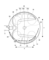
- FIG. 2 is a plan view showing a schematic configuration of the internal combustion engine in the cylinder axis direction.
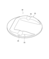
- FIG. 3 is a perspective view of a piston showing the shape of the piston top surface.
- FIG. 4 is a central cross-sectional view showing the piston.
- FIG. 5(A) is a cross-sectional view of a main part of an internal combustion engine showing a state in which the piston has risen to the midpoint during the compression stroke
- FIG. 5(B) is a cross-sectional view of a main part of an internal combustion engine showing a state in which the piston has risen to top dead center during the compression stroke.
- FIG. 5(A) is a cross-sectional view of a main part of an internal combustion engine showing a state in which the piston has risen to top dead center during the compression stroke.
- FIG. 5(A) is a cross
- FIG. 6 is a perspective view of a main part of a piston, showing the airflow guided by the piston top surface.
- FIG. 7 is a plan view of the piston top surface in the cylinder axial direction, showing the flame injected from the sub-chamber.
- FIG. 8 is a perspective view of the piston top surface showing the grooves provided in the side guide portions.
- 9(A) and 9(B) are perspective views of the piston top surface showing first and second alternative embodiments of the protrusions.
- a pre-chamber internal combustion engine (hereinafter simply referred to as an "internal combustion engine") that employs a direct-injection internal combustion engine according to one embodiment of the present invention will be described with reference to Figures 1 to 8. Note that the present invention is not limited to the embodiment described below, and various modifications are possible as long as they have substantially the same configuration as this embodiment and provide similar effects.
- the cylinder axis direction Z of the internal combustion engine 1 refers to the direction in which the piston slides along the cylinder.
- the intake and exhaust direction X refers to the direction connecting the intake port and the exhaust port.
- the "intake side” refers to the intake port side of the intake and exhaust direction X
- the “exhaust side” refers to the exhaust port side of the intake and exhaust direction X.
- the intake and exhaust direction X is also the fuel injection direction by the fuel injection nozzle.
- crankshaft direction Y refers to the extension direction of the crankshaft, and refers to the direction perpendicular to the cylinder axis direction Z and the intake and exhaust direction X.
- the crankshaft direction Y is also the direction of the cylinder rows arranged along the crankshaft. This configuration can be seen in FIG. 2.
- FIG. 1 is a cross-sectional view of a main portion showing a schematic configuration of an internal combustion engine according to an embodiment of the present disclosure
- Fig. 2 is a plan view showing a schematic configuration of the internal combustion engine in a cylinder axial direction Z.
- the internal combustion engine 1 includes a main combustion chamber 10 and an auxiliary combustion chamber 20 which form combustion chambers, an ignition plug 4, and a fuel injection nozzle 5.
- the internal combustion engine 1 of this embodiment is an in-line internal combustion engine in which a plurality of cylinders, each including a main combustion chamber 10 and an auxiliary combustion chamber 20, are arranged in series along a crankshaft 2.
- the arrangement of the cylinders may be a V-type or a horizontal type.
- the main chamber 10 is a space defined by a cylinder block 11 that forms a cylindrical cylinder 11a extending in the vertical direction, a cylinder head 12 that covers the upper end side of the cylinder 11a, and a piston 13 that reciprocates within the cylinder 11a.
- the auxiliary chamber 20 is a space defined by an auxiliary chamber wall 21 provided in the cylinder head 12.
- the auxiliary chamber 20 has the auxiliary chamber wall 21 and a communication passage 22 (injection port) that connects the main chamber 10 and the auxiliary chamber 20.
- the spark plug 4 is supported in the center of the cylinder head 12 and its tip side is disposed in the sub-chamber 20 separated by the sub-chamber wall 21 .
- a pair of intake ports 15 that are opened and closed by intake valves 14 are connected to one side of the cylinder head 12 in the intake and exhaust direction X, and a pair of exhaust ports 17 that are opened and closed via exhaust valves 16 are connected to the other side.
- a fuel supply nozzle 18 is disposed in the intake port 15. The fuel supply nozzle 18 can supply fuel into the main chamber 10 when the intake valve 14 opens. This configuration can be seen in Figures 1 and 2.
- the intake port 15 is connected to an intake passage (not shown), and the exhaust port 17 is connected to an exhaust passage (not shown).
- the piston 13 has a piston top surface 30 that faces the cylinder head 12 and thereby constitutes the lower part of the main chamber 10, and a pin hole 13a that is connected to the upper end side of the connecting rod 3 via a piston pin 19, and is connected to the crankshaft 2 via the connecting rod 3. This causes the piston 13 to reciprocate between the bottom dead center and the top dead center in the cylinder 11a in the vertical direction. See Figure 1 for this configuration.
- the auxiliary chamber wall 21 has a circular cross section centered on the cylinder axis (the axis that passes through the center of the piston 13 and extends in the cylinder axis direction Z) when viewed from above in the cylinder axis direction Z. This configuration can be seen in Figure 2.
- the auxiliary chamber wall 21 has a lower part that is hemispherical when viewed in the intake/exhaust direction X and the crank axis direction Y. This configuration can be seen in Figure 1.
- the communication passages 22 are formed along the circumferential direction of the auxiliary chamber wall 21 when viewed in a plan view in the cylinder axial direction Z, and connect the main chamber 10 and the auxiliary chamber 20.
- the fuel injection nozzle 5 is disposed outside the sub chamber 20, on the periphery of the cylinder head 12.
- the fuel injection nozzle 5 is disposed on the intake valve 14 side in the intake/exhaust direction X, more specifically, between the pair of intake valves 14, 14.
- This configuration can be seen in FIG. 2.
- the fuel injection nozzle 5 injects fuel directly toward the spark plug 4 in the auxiliary combustion chamber 20.
- a first communication passage 22A which is one of the communication passages 22, is arranged on the line of fire of the fuel injection from the fuel injection nozzle 5, i.e., on an extension line of the fuel injection port of the fuel injection nozzle 5. Therefore, the fuel injected from the fuel injection nozzle 5 can be directly supplied into the auxiliary combustion chamber 20 via the first communication passage 22A.
- the extension line of the first communication passage 22A also passes below the fuel injection nozzle 5. This configuration can be seen in Figures 1 and 5(A).
- the amount of fuel injected by the fuel injection nozzle 5 and the timing of fuel injection are controlled by a control
- the above-described internal combustion engine 1 can output power from the crankshaft 2 by repeating an intake stroke, a compression stroke, an expansion stroke, and an exhaust stroke to cause the piston 13 to reciprocate within the cylinder 11 a.
- fuel is supplied into the main combustion chamber 10 from a fuel supply nozzle 18 in the intake port 15 during the intake stroke.
- the intake air introduced into the main chamber 10 from the intake port 15 during the intake stroke is guided to the piston top surface 30, forming a tumble flow, which is a vortex air flow in the vertical direction (rotating around the crankshaft direction Y), within the main chamber 10.
- the shape of the piston top surface 30 makes it possible to stably form a tumble flow that does not impede the fuel injection from the fuel injection nozzle 5 to the spark plug 4 when the piston 13 moves upward during the compression stroke.
- the specific shape of the piston top surface 30 will be described later.
- the fuel and air-fuel mixture supplied to the auxiliary combustion chamber 20 is ignited by the spark plug 4 and combusted in the auxiliary combustion chamber 20.
- a flame F generated in the auxiliary combustion chamber 20 is injected from the communication passage 22 toward the main combustion chamber 10. This configuration can be seen in FIG. 7.
- the mixture formed in the main chamber 10 is combusted by the flame F injected from the auxiliary chamber 20 toward the main chamber 10 .
- Figure 3 is a perspective view of a piston showing the shape of the piston top surface
- Figure 4 is a central cross-sectional view of a piston
- Figure 5(A) is a cross-sectional view of a main part of an internal combustion engine showing the state in which the piston has risen to an intermediate point during the compression stroke, which will be described later
- Figure 5(B) is a cross-sectional view of a main part of an internal combustion engine showing the state in which the piston has risen to top dead center during the compression stroke
- Figure 6 is a perspective view of a main part of a piston showing the flow of the airflow guided by the piston top surface
- Figure 7 is a plan view of the piston top surface in the cylinder axial direction Z, showing the flame ejected from the auxiliary chamber.
- the circular piston top surface 30 When viewed from above in the cylinder axial direction Z, the circular piston top surface 30 has an inclined surface 31 and a flat surface 32 that are provided at the center of the crankshaft direction Y and extend along the intake/exhaust direction X, a pair of lateral guide portions 33, 33 provided on both sides of the inclined surface 31 and the flat surface 32 in the crankshaft direction Y, and a protrusion portion 34 and a valve recess 39 provided on the intake side of the inclined surface 31.
- the inclined surface 31 is formed on the intake port 15 side (intake side) in the intake/exhaust direction X, i.e., on the side where the fuel injection nozzle 5 is located.
- the inclined surface 31 extends in the intake/exhaust direction X and inclines toward the cylinder head 12 as it approaches the fuel injection nozzle 5.
- the inclined surface 31 is inclined upward toward the intake side.
- the inclined surface 31 has a first inclined surface 31a and a second inclined surface 31b that are continuously formed in that order from the exhaust side (the side opposite to the fuel injection nozzle 5) along the intake/exhaust direction X.
- the second inclined surface 31b which is disposed on the intake side, has a shorter length in the intake/exhaust direction X and a steeper angle of upward inclination toward the cylinder head 12. This configuration can be seen in FIG. 4.
- the inclined surface 31 is formed by the first inclined surface 31a and the second inclined surface 31b having different angles, but the inclined surface 31 may be formed by three or more inclined surfaces having different angles as long as the angle of the upward inclination becomes steeper in multiple stages toward the intake side (the fuel injection nozzle 5 side).
- the angle of the top of the inclined surface 31, in this embodiment, the angle of the second inclined surface 31b, is set so that when the vertical position of the piston 13 is within a predetermined range, the position where an extension line of the second inclined surface 31b parallel to the intake/exhaust direction X (hereinafter simply referred to as the extension line of the inclined surface 31) intersects with the wall surface of the cylinder 11a is lower (to the piston side) in the cylinder axial direction Z than the fuel injection nozzle 5.
- the intersection point of the extension line of the inclined surface 31 and the wall surface of the cylinder 11a is defined as a first contact point H1. This configuration can be seen in FIG. 4.
- the inclined surface 31 is formed so that, when the piston 13 is at least at the midpoint between the top dead center and the bottom dead center and closer to the bottom dead center, an extension of the inclined surface 31 intersects with the wall surface of the cylinder 11a at a first contact point H1.
- FIG. 5(A) the inclined surface 31 is formed so that, when the piston 13 is at the top dead center, an extension line of the inclined surface 31 passes between the fuel injection nozzle 5 and the spark plug 4 and intersects with the lower surface of the cylinder head 12. This configuration can be seen in FIG. 5(B).
- the inclined surface 31 be formed so that, at the timing when fuel is injected from the fuel injection nozzle 5, an extension line of the inclined surface 31 intersects with the wall surface of the cylinder 11a at the first contact point H1, as shown in Figure 5 (A).
- the higher the engine speed the closer the vertical position of the piston 13 is to the bottom dead center at the timing when fuel is injected from the fuel injection nozzle 5.
- the inclined surface 31 is formed so that when the piston 13 reaches top dead center, its top is located below the center line extending from the injection port 22a of the first communication passage 22A of the auxiliary chamber 20 when viewed in the crankshaft direction Y.
- This configuration can be seen in FIG. 5(B). This configuration prevents the inclined surface 31 from being directly hit by the flame F injected from the auxiliary chamber 20 toward the main chamber 10, and thus preventing the inclined surface 31 from being deteriorated.
- a downward slope 36 is formed, which slopes downward as it approaches the intake side.
- the downward slope 36 is connected to the top of the inclined surface 31.
- the flat surface 32 extends in the intake/exhaust direction X from the exhaust side end of the piston top surface 30 toward the intake side, and is continuous with the inclined surface 31.
- the flat surface 32 is formed as a plane extending parallel to the intake/exhaust direction X and the crankshaft direction Y so as to be perpendicular to the cylinder axial direction Z. This configuration may be seen in FIG.
- the flat surface 32 may be any surface capable of guiding the airflow toward the inclined surface by a smooth plane, and is not limited to a plane perpendicular to the cylinder axial direction Z.
- the flat surface 32 may be a gently inclined surface having an angle with the inclined surface 31.
- the intake side from the center of the piston 13 is defined as the inclined surface 31.
- the lateral guide portion 33 has a lateral guide surface 33a that slopes from the exhaust side end toward the cylinder head 12, a lateral extension surface 33b that extends approximately parallel to the piston top surface 30 from the intake side end of the lateral guide surface 33a, and a lateral downward surface 33c that slopes downward from the intake side end of the lateral extension surface 33b toward the piston top surface 30. That is, the side guide portion 33 protrudes toward the cylinder head 12 in the cylinder axial direction Z when viewed in the crankshaft direction Y, extends along the intake/exhaust direction X, and is formed in a generally mountain shape with the intake side end of the side guide surface 33a as the apex. This configuration can be seen in Fig. 4. Note that the side guide portion 33 may have the side extension surface 33b inclined in the same manner as the side downward surface 33c. In this case, the side extension surface 33b and the side downward surface 33c are in the same place.
- the angle of the side guide surface 33a is set so that, when the vertical position of the piston 13 is within a predetermined range, the position where an extension line of the side guide surface 33a parallel to the intake/exhaust direction X (hereinafter simply referred to as the extension line of the side guide surface 33a) intersects with the wall surface of the cylinder 11a is lower (to the piston side) in the cylinder axial direction Z than the first contact point H1. At this time, the intersection point of the extension line of the side guide surface 33a and the wall surface of the cylinder 11a is defined as the second contact point H2.
- the side guide surface 33a is formed to have a gentler inclination than the inclined surface 31.
- the top of the side guide surface 33a is located closer to the wall surface of the cylinder 11a in the intake/exhaust direction X than the top of the inclined surface 31.
- the second contact point H2 is located lower in the cylinder axial direction Z than the first contact point H1, and the intake/exhaust direction X is on the exhaust side.
- the side guide surface 33a is formed so that, when an extension line of the side guide surface 33a is extended along the inner wall of the cylinder 11a to the intake side in the intake/exhaust direction X while maintaining the vertical angle from the second contact point H2, the extension line reaches a third contact point H3 below the first contact point H1 below the fuel injection nozzle 5 (a position overlapping with the fuel injection nozzle 5 as viewed in the cylinder axial direction Z).
- a third contact point H3 below the first contact point H1 below the fuel injection nozzle 5 (a position overlapping with the fuel injection nozzle 5 as viewed in the cylinder axial direction Z).
- the lateral downward surface 33c is inclined downward from the lateral extension surface 33b toward the intake side, and smoothly connects to the downward surface 36 arranged on the intake side of the inclined surface 31. In other words, the lateral downward surface 33c and the downward surface 36 are flush with each other. With this configuration, it is possible to prevent the airflow that flows in the intake/exhaust direction X along the inclined surface 31 and the flat surface 32, and the airflow that does not separate from the inclined surface 31 and the airflow that does not separate from the lateral guide surface 33a, from being disturbed on the intake side of the piston top surface 30.
- Figures 2 and 6 refer to Figures 2 and 6.
- the first separation angle ⁇ between the extension line of the inclined surface 31 and the downward surface 36 is set to be larger than the second separation angle ⁇ between the extension line of the lateral guide surface 33a and the lateral extension surface 33b.
- the airflow guided by the inclined surface 31, where the flow is strongest is more likely to separate from the top of the inclined surface 31, making the tumble flow guided by the piston top surface 30 more stable.
- the first separation angle ⁇ is larger than the second separation angle ⁇ .
- the guide width which is the width of the inclined surface 31 and the flat surface 32 in the crankshaft direction Y, is formed so as to gradually narrow toward the intake side in the intake and exhaust direction X.
- the inner surfaces (surfaces facing the cylinder axis) of the side guide parts 33 are inclined in the crankshaft direction Y so as to approach each other toward the intake side.
- the outer surfaces (surfaces facing the wall surface of the cylinder 11a) of the side guide parts 33 are formed in an arc shape along the wall surface of the cylinder 11a in the intake and exhaust direction X.
- the side guide parts 33 extend from the exhaust side to the intake side of the cylinder axis in the intake and exhaust direction X.
- each side guide part 33, 33 is largest at the point located at the center of the piston 13 in the intake and exhaust direction X.
- the inclination angle of the inner surface of the side guide parts 33 is determined so that the width in the crankshaft direction Y on the intake side of the point located at the center of the piston 13 in the intake and exhaust direction X of each side guide part 33, 33 is approximately constant.
- the protrusion 34 is a protrusion formed on the downward surface 36 toward the upper side.
- the protrusion 34 is formed so that the width in the crankshaft direction Y decreases toward the exhaust side in the intake and exhaust direction X.
- the width in the crankshaft direction Y of the intake side end of the protrusion 34 is formed larger than the width in the crankshaft direction Y of the tip of the fuel injection nozzle 5. This configuration can be seen in FIG. 2.
- the protrusion 34 is located between a pair of intake valves 14, 14.
- the protrusion 34 is formed by utilizing a trapezoidal portion of the valve recess 39, which is a recess formed according to the shape of the pair of intake valves 14, 14, between a pair of recesses corresponding to each intake valve 14, 14, as viewed from the cylinder axial direction Z. That is, the valve recess 39 is formed flush with the downward surface 36 and the lateral downward surface 33c, and the protrusion 34 protrudes upward from the downward surface 36.
- the protrusion 34 may be configured so that the surface in the crankshaft direction Y when viewed in the intake/exhaust direction X is inclined upward as it approaches the center of the protrusion 34. This configuration may be seen in FIG. 9(A).
- the shape of the protrusion 34 may be a trapezoid when viewed in the cylinder axial direction Z as shown in FIG. 2, or a diamond shape or the like. In other words, it is sufficient that the width of the exhaust side end of the protrusion 34 in the crankshaft direction Y becomes smaller as it approaches the exhaust side. This configuration may be seen in FIG. 9(B).
- the flow speed of the air flowing on the fuel injection nozzle 5 side of the inclined surface 31 becomes faster, and the tumble flow becomes more stable.
- the inclination angle of the inclined surface 31 gradually larger toward the fuel injection nozzle 5 side, the airflow guided by the inclined surface 31 can be easily separated smoothly at the end of the inclined surface 31. Therefore, the tumble flow formed by the inclined surface 31 becomes more stable.
- the flat surface 32 described above makes the downstream side of the airflow flowing along the piston top surface 30 flat, which prevents the airflow flowing toward the inclined surface 31 from separating from the piston top surface 30, making the tumble flow more stable.
- the above-described lateral guide portion 33 can guide the airflow flowing along the outer edge of the piston top surface 30 toward the fuel injection nozzle 5 to a second contact point H2 below the first contact point H1. This makes it possible to suppress the airflow guided by the lateral guide portions 33 from disturbing the airflow guided by the inclined surfaces 31. As a result, the above-mentioned tumble flow formed in the main chamber 10 by the piston top surfaces 30 becomes more stable.
- the lateral guide portion 33 is formed so that when the extension line of the lateral guide surface 33a is extended along the inner wall of the cylinder 11a toward the fuel injection nozzle 5 while maintaining the vertical angle from the second contact point H2, it reaches the third contact point H3 below the first contact point H1.
- the airflow guided by the lateral guide portion 33 can push up the airflow guided by the inclined surface 31, making the tumble flow more stable.
- the lateral guide portion 33 is formed so that the lateral downward surface 33c and the downward surface 36 are flush with each other, it is possible to suppress turbulence of the air flow flowing along the lateral downward surface 33c and the downward surface 36 without peeling off from the lateral guide surface 33a and the inclined surface 31, making the tumble flow more stable.
- the width of the lateral guide portion 33 approximately constant from its widest point in the crankshaft direction Y toward the fuel injection nozzle 5, it is possible to prevent the airflow flowing along the lateral guide portion 33 from being turbulent in the crankshaft direction Y, making the tumble flow more stable.
- the above-mentioned protrusion 34 allows the flame F1, which is part of the flame F injected from the auxiliary chamber 20 toward the main chamber 10 in a plan view in the cylinder axial direction Z and is injected from the first communication passage 22A toward the fuel injection nozzle 5, to be divided in the crankshaft direction Y and deflected away from the fuel injection nozzle 5. This reduces the effect of the flame F1 injected from the first communication passage 22A on the fuel injection nozzle 5.
- Fig. 8 is a perspective view of the piston top surface showing the groove provided in the side guide portion 33.
- the side guide portion 33 may be configured to extend in a direction intersecting the extending direction of the side guide portion 33 and to have a groove portion 35 provided as a passage portion that communicates between the inside and outside of the side guide portion 33.
- the groove portion 35 is recessed in the cylinder axial direction Z, extends in a direction intersecting the extension direction of the side guide portion 33, i.e., in the crankshaft direction Y, and opens on the inner and outer surfaces of the side guide portion 33.
- the depth of the groove 35 in the vertical direction (cylinder axial direction Z) is gradually increased from the outer side (the center side of the piston 13) toward the inner side in the extending direction of the groove 35.
- the width of the groove 35 in the extending direction of the side guide portion 33 (the intake/exhaust direction X) is formed so as to gradually increase from the inside toward the outside in the extending direction of the groove 35 .
- the groove 35 having this configuration by providing a pair of side guide portions 33 on the edge portion of the piston top surface 30, the flame F injected from the auxiliary chamber 20 can be efficiently transmitted to the gap formed between the outside of the side guide portions 33 in the width direction (crankshaft direction Y) and the wall surface of the cylinder 11a. Therefore, the side guide portions 33 provided on the piston top surface 30 can suppress the inhibition of the spread of the combustion of the mixture outside the side guide portions 33. In addition, the vertical depth of the groove portion 35 becomes deeper toward the inside in the extension direction of the groove portion 35, so that the flame F sprayed from the auxiliary chamber 20 is more easily guided to the groove portion 35.
- the width of the groove 35 becomes wider from the inside toward the outside in the extension direction of the groove 35, so that the flame F is more likely to propagate over a wider area on the outside in the width direction of the side guide portion 33. Therefore, the mixture is more likely to burn on the outside of the side guide portion 33.
- the groove portion 35 is a groove for guiding the flame F injected from the injection port 22a of the auxiliary chamber 20 from the inside to the outside of the side guide portion 33, the position is not limited to the position shown in Fig. 8. Specifically, the groove portion 35 only needs to be provided at a position where an extension line from each injection port 22a of the auxiliary chamber 20 intersects with the side guide portion 33 in a plan view in the cylinder axial direction Z, so as to extend along the extension line from the injection port 22a, and a configuration in which a plurality of groove portions are provided is also possible. However, the grooves 35 are not provided at positions adjacent to the tops of the inclined surfaces 31 of the lateral guide portions 33. This makes it possible to prevent the grooves 35 from disrupting the flow of the airflow guided along the inclined surfaces 31.
- the side guide portion 33 may be configured so that the width in the crankshaft direction Y on the exhaust side of the groove portion 35 is greater than the width in the crankshaft direction Y on the intake side of the groove portion 35. This makes it possible to suppress turbulence in the airflow caused by the airflow passing along the side guide portion 33 through the groove portion 35.
- the groove portion 35 is not limited to a groove recessed into the upper surface of the side guide portion 33, but may be a through hole drilled in a direction intersecting the extension direction of the side guide portion 33.
- the present embodiment shows an example of the present invention, and the present invention is not limited to the present embodiment.
- various modifications and improvements can be made to the present embodiment, and such modifications and improvements can also be included in the present invention.
- the features of the present invention are not limited to the internal combustion engine 1 using the auxiliary chamber 20 that houses the spark plug 4 within the main chamber 10, and similar effects can be expected as long as the internal combustion engine is provided with a fuel injection nozzle 5 that injects fuel toward the spark plug 4.
- the internal combustion engine of the present disclosure uses gasoline, the fuel is not limited to this and may be other fuels such as alcohol.
- the present specification discloses the following: (1) a cylinder formed by a cylinder block; a cylinder head covering one end of the cylinder; a piston having a top surface facing the cylinder head and reciprocating within the cylinder; a spark plug disposed in a center portion of the cylinder head in a combustion chamber defined between the cylinder, the cylinder head, and the piston; a fuel injection nozzle disposed within the combustion chamber; an intake port and an exhaust port provided in the cylinder head on either side of the spark plug;
- a cylinder injection type internal combustion engine comprising: the fuel injection nozzle is disposed on one side in an intake/exhaust direction connecting the intake port and the exhaust port, and injects fuel toward the ignition plug; a pair of side guide portions are formed on the top surface of the piston, the pair of side guide portions being disposed so as to sandwich the inclined surface in a crank axial direction perpendicular to the intake/exhaust direction and a cylinder axial direction which is a reciprocating direction of the cylinder, and the pair of side guide
- the inclined surface is formed so that the inclination angle toward the cylinder head side increases stepwise toward the one side.
- a direct injection type internal combustion engine according to claim 1. According to this configuration, the airflow guided by the inclined surface 31 is more likely to separate from the top of the inclined surface 31. Also, compared to a case where the angle of the inclined surface 31 is made steep from the beginning, it is possible to suppress the inclined surface 31 from acting as resistance to the airflow.
- the side guide portion has a side guide surface that inclines toward the cylinder head as it approaches the one side,
- the top surface is formed with a downward surface that slopes toward the cylinder head from the top of the inclined surface toward the one side, and a lateral extension surface that extends from the top of the side guide surface to the one side,
- the inclined surface is formed so that an angle formed between an extension line of the inclined surface and the downward surface is larger than an angle formed between an extension line of the side guide surface and the side extension surface.
- a direct injection type internal combustion engine according to (1) or (2) According to this configuration, the airflow separates more easily from the main inclined surface than from the side guide surface 33a, so that the tumble flow formed on the piston top surface 30 becomes more stable.
- the width of the side guide portion in the crank axial direction is widest at a portion corresponding to a center of the piston in the intake/exhaust direction, and is formed to be approximately constant on the one side from the widest portion.
- a sub-chamber for accommodating the ignition plug is provided in the combustion chamber,
- the auxiliary chamber is provided with an injection port that communicates the combustion chamber with the auxiliary chamber and injects flame from the auxiliary chamber to the combustion chamber, a passage portion extending in the crankshaft direction and communicating between an inner surface and an outer surface of the side guide portion is formed in the side guide portion, The passage portion is formed on an extension line of the injection port.
- a direct injection type internal combustion engine according to any one of (1) to (4). According to this configuration, the flame injected from the auxiliary chamber can be efficiently guided into the gap between the side guide portion 33 and the wall surface of the cylinder 11a, thereby achieving both the formation of a stable tumble flow and combustion efficiency.
Landscapes
- Engineering & Computer Science (AREA)
- Chemical & Material Sciences (AREA)
- Combustion & Propulsion (AREA)
- Mechanical Engineering (AREA)
- General Engineering & Computer Science (AREA)
- Combustion Methods Of Internal-Combustion Engines (AREA)
Priority Applications (2)
| Application Number | Priority Date | Filing Date | Title |
|---|---|---|---|
| PCT/JP2023/012054 WO2024201622A1 (ja) | 2023-03-24 | 2023-03-24 | 筒内噴射式内燃機関 |
| JP2025509257A JPWO2024201622A1 (https=) | 2023-03-24 | 2023-03-24 |
Applications Claiming Priority (1)
| Application Number | Priority Date | Filing Date | Title |
|---|---|---|---|
| PCT/JP2023/012054 WO2024201622A1 (ja) | 2023-03-24 | 2023-03-24 | 筒内噴射式内燃機関 |
Publications (1)
| Publication Number | Publication Date |
|---|---|
| WO2024201622A1 true WO2024201622A1 (ja) | 2024-10-03 |
Family
ID=92903977
Family Applications (1)
| Application Number | Title | Priority Date | Filing Date |
|---|---|---|---|
| PCT/JP2023/012054 Ceased WO2024201622A1 (ja) | 2023-03-24 | 2023-03-24 | 筒内噴射式内燃機関 |
Country Status (2)
| Country | Link |
|---|---|
| JP (1) | JPWO2024201622A1 (https=) |
| WO (1) | WO2024201622A1 (https=) |
Citations (5)
| Publication number | Priority date | Publication date | Assignee | Title |
|---|---|---|---|---|
| JPH09280055A (ja) * | 1996-04-15 | 1997-10-28 | Nissan Motor Co Ltd | 直接筒内噴射式火花点火エンジン |
| JP2000027650A (ja) * | 1998-07-13 | 2000-01-25 | Nissan Motor Co Ltd | 筒内噴射式内燃機関のピストン |
| JP2001342836A (ja) * | 2000-03-29 | 2001-12-14 | Mazda Motor Corp | 火花点火式直噴エンジン |
| JP2007100547A (ja) * | 2005-09-30 | 2007-04-19 | Mazda Motor Corp | 往復動ピストン型火花点火式直噴エンジン |
| JP2013113120A (ja) * | 2011-11-25 | 2013-06-10 | Honda Motor Co Ltd | 内燃機関 |
-
2023
- 2023-03-24 WO PCT/JP2023/012054 patent/WO2024201622A1/ja not_active Ceased
- 2023-03-24 JP JP2025509257A patent/JPWO2024201622A1/ja active Pending
Patent Citations (5)
| Publication number | Priority date | Publication date | Assignee | Title |
|---|---|---|---|---|
| JPH09280055A (ja) * | 1996-04-15 | 1997-10-28 | Nissan Motor Co Ltd | 直接筒内噴射式火花点火エンジン |
| JP2000027650A (ja) * | 1998-07-13 | 2000-01-25 | Nissan Motor Co Ltd | 筒内噴射式内燃機関のピストン |
| JP2001342836A (ja) * | 2000-03-29 | 2001-12-14 | Mazda Motor Corp | 火花点火式直噴エンジン |
| JP2007100547A (ja) * | 2005-09-30 | 2007-04-19 | Mazda Motor Corp | 往復動ピストン型火花点火式直噴エンジン |
| JP2013113120A (ja) * | 2011-11-25 | 2013-06-10 | Honda Motor Co Ltd | 内燃機関 |
Also Published As
| Publication number | Publication date |
|---|---|
| JPWO2024201622A1 (https=) | 2024-10-03 |
Similar Documents
| Publication | Publication Date | Title |
|---|---|---|
| KR100304232B1 (ko) | 성층급기연소및균질급기연소가가능한관내분사식가솔린엔진 | |
| US6615794B2 (en) | Direct cylinder injection-type spark ignition internal combustion engine | |
| EP1350014B1 (en) | Piston for internal combustion engines | |
| US10718258B2 (en) | Spark-ignited direct-injection engine combustion systems | |
| JP3585766B2 (ja) | ガソリン直噴エンジン | |
| JP2005195001A (ja) | 直接噴射式エンジン | |
| US6684848B2 (en) | Direct-injection spark-ignition engine | |
| CN100381682C (zh) | 缸内燃料喷射式内燃机 | |
| JP6405352B2 (ja) | 直噴内燃機関のピストン | |
| JP3777660B2 (ja) | 筒内直接噴射式火花点火内燃機関 | |
| WO2024201622A1 (ja) | 筒内噴射式内燃機関 | |
| WO2018180132A1 (ja) | 火花点火式内燃機関 | |
| WO2024201621A1 (ja) | 筒内噴射式内燃機関 | |
| WO2024201623A1 (ja) | 内燃機関 | |
| WO2024201624A1 (ja) | 筒内噴射式内燃機関 | |
| WO2024201620A1 (ja) | 筒内噴射式内燃機関 | |
| US6289870B1 (en) | Direct fuel injection-type spark-ignition internal combustion engine | |
| JP3644329B2 (ja) | 筒内噴射型内燃機関 | |
| CN101631939B (zh) | 缸内喷射式内燃机 | |
| US11408367B2 (en) | Internal combustion engine | |
| WO2018180129A1 (ja) | 火花点火式内燃機関 | |
| JP4088565B2 (ja) | 筒内噴射式内燃機関および筒内噴射式内燃機関の混合気形成方法 | |
| KR100303976B1 (ko) | 가솔린엔진의연소실 | |
| JP7283850B2 (ja) | 内燃機関 | |
| JP2025151873A (ja) | エンジンの燃焼室構造 |
Legal Events
| Date | Code | Title | Description |
|---|---|---|---|
| 121 | Ep: the epo has been informed by wipo that ep was designated in this application |
Ref document number: 23930262 Country of ref document: EP Kind code of ref document: A1 |
|
| DPE1 | Request for preliminary examination filed after expiration of 19th month from priority date (pct application filed from 20040101) | ||
| WWE | Wipo information: entry into national phase |
Ref document number: 2025509257 Country of ref document: JP |
|
| NENP | Non-entry into the national phase |
Ref country code: DE |
|
| 122 | Ep: pct application non-entry in european phase |
Ref document number: 23930262 Country of ref document: EP Kind code of ref document: A1 |