WO2024201576A1 - 電気化学セル - Google Patents
電気化学セル Download PDFInfo
- Publication number
- WO2024201576A1 WO2024201576A1 PCT/JP2023/011860 JP2023011860W WO2024201576A1 WO 2024201576 A1 WO2024201576 A1 WO 2024201576A1 JP 2023011860 W JP2023011860 W JP 2023011860W WO 2024201576 A1 WO2024201576 A1 WO 2024201576A1
- Authority
- WO
- WIPO (PCT)
- Prior art keywords
- region
- electrode layer
- metal support
- hydrogen electrode
- layer
- Prior art date
- Legal status (The legal status is an assumption and is not a legal conclusion. Google has not performed a legal analysis and makes no representation as to the accuracy of the status listed.)
- Ceased
Links
Images



Classifications
-
- C—CHEMISTRY; METALLURGY
- C25—ELECTROLYTIC OR ELECTROPHORETIC PROCESSES; APPARATUS THEREFOR
- C25B—ELECTROLYTIC OR ELECTROPHORETIC PROCESSES FOR THE PRODUCTION OF COMPOUNDS OR NON-METALS; APPARATUS THEREFOR
- C25B1/00—Electrolytic production of inorganic compounds or non-metals
- C25B1/01—Products
- C25B1/02—Hydrogen or oxygen
- C25B1/04—Hydrogen or oxygen by electrolysis of water
- C25B1/042—Hydrogen or oxygen by electrolysis of water by electrolysis of steam
-
- C—CHEMISTRY; METALLURGY
- C25—ELECTROLYTIC OR ELECTROPHORETIC PROCESSES; APPARATUS THEREFOR
- C25B—ELECTROLYTIC OR ELECTROPHORETIC PROCESSES FOR THE PRODUCTION OF COMPOUNDS OR NON-METALS; APPARATUS THEREFOR
- C25B11/00—Electrodes; Manufacture thereof not otherwise provided for
- C25B11/02—Electrodes; Manufacture thereof not otherwise provided for characterised by shape or form
- C25B11/03—Electrodes; Manufacture thereof not otherwise provided for characterised by shape or form perforated or foraminous
- C25B11/031—Porous electrodes
-
- C—CHEMISTRY; METALLURGY
- C25—ELECTROLYTIC OR ELECTROPHORETIC PROCESSES; APPARATUS THEREFOR
- C25B—ELECTROLYTIC OR ELECTROPHORETIC PROCESSES FOR THE PRODUCTION OF COMPOUNDS OR NON-METALS; APPARATUS THEREFOR
- C25B9/00—Cells or assemblies of cells; Constructional parts of cells; Assemblies of constructional parts, e.g. electrode-diaphragm assemblies; Process-related cell features
-
- H—ELECTRICITY
- H01—ELECTRIC ELEMENTS
- H01M—PROCESSES OR MEANS, e.g. BATTERIES, FOR THE DIRECT CONVERSION OF CHEMICAL ENERGY INTO ELECTRICAL ENERGY
- H01M4/00—Electrodes
- H01M4/86—Inert electrodes with catalytic activity, e.g. for fuel cells
-
- H—ELECTRICITY
- H01—ELECTRIC ELEMENTS
- H01M—PROCESSES OR MEANS, e.g. BATTERIES, FOR THE DIRECT CONVERSION OF CHEMICAL ENERGY INTO ELECTRICAL ENERGY
- H01M4/00—Electrodes
- H01M4/86—Inert electrodes with catalytic activity, e.g. for fuel cells
- H01M4/90—Selection of catalytic material
-
- H—ELECTRICITY
- H01—ELECTRIC ELEMENTS
- H01M—PROCESSES OR MEANS, e.g. BATTERIES, FOR THE DIRECT CONVERSION OF CHEMICAL ENERGY INTO ELECTRICAL ENERGY
- H01M8/00—Fuel cells; Manufacture thereof
- H01M8/10—Fuel cells with solid electrolytes
- H01M8/12—Fuel cells with solid electrolytes operating at high temperature, e.g. with stabilised ZrO2 electrolyte
- H01M8/1213—Fuel cells with solid electrolytes operating at high temperature, e.g. with stabilised ZrO2 electrolyte characterised by the electrode/electrolyte combination or the supporting material
- H01M8/1226—Fuel cells with solid electrolytes operating at high temperature, e.g. with stabilised ZrO2 electrolyte characterised by the electrode/electrolyte combination or the supporting material characterised by the supporting layer
Definitions
- the present invention relates to an electrochemical cell.
- electrochemical cells electrolysis cells, fuel cells, etc.
- a cell body disposed on a metal support are known (see, for example, Patent Document 1).
- the metal support has a plurality of communication holes formed on its main surface.
- the cell body is formed on the main surface of the metal support and has a first electrode layer covering the plurality of communication holes, a second electrode layer, and an electrolyte layer disposed between the first electrode layer and the second electrode layer.
- the first electrode layer contains nickel as a metal for imparting electrical conductivity. The nickel contained in the first electrode layer becomes nickel oxide in an oxidizing atmosphere and becomes metallic nickel in a reducing atmosphere.
- the first electrode layer expands/contracts due to the oxidation-reduction cycle. Specifically, when the first electrode layer is reduced before the operation of the electrochemical cell, nickel oxide becomes metallic nickel and the first electrode layer contracts, and when the operation of the electrochemical cell is stopped and the first electrode layer changes from a reducing atmosphere to an oxidizing atmosphere, metallic nickel becomes nickel oxide and the first electrode layer expands.
- the objective of the present invention is to provide an electrochemical cell that can prevent the first electrode layer from peeling off from the metal support.
- the electrochemical cell according to the first aspect of the present invention comprises a metal support having a plurality of through holes formed on a main surface, a first electrode layer formed on the main surface and covering the plurality of through holes, a second electrode layer, and a cell body having an electrolyte layer disposed between the first electrode layer and the second electrode layer.
- the first electrode layer has a first region within 5 ⁇ m in the thickness direction from a first surface that contacts the metal support, a second region within 5 ⁇ m in the thickness direction from a second surface that contacts the electrolyte layer, and a third region between the first region and the second region.
- Each of the first region, the second region, and the third region contains nickel and an oxide ion conductive material.
- the nickel content in the first region is lower than the nickel content in the third region.
- the electrochemical cell according to the second aspect of the present invention is the electrochemical cell according to the first aspect, in which the nickel content in the second region is lower than the nickel content in the third region.
- the electrochemical cell according to the third aspect of the present invention is the electrochemical cell according to the first or second aspect, in which the nickel content in the second region is lower than the nickel content in the first region.
- the electrochemical cell according to a fourth aspect of the present invention relates to the above-mentioned first to fourth aspects, and the first electrode layer has a fourth region disposed inside at least one of the plurality of communication holes.
- the fourth region contains nickel and an oxide ion conductive material.
- the nickel content in the fourth region is lower than the nickel content in the third region.
- the present invention provides an electrochemical cell that can prevent the first electrode layer from peeling off from the metal support.
- FIG. 1 is a plan view of an electrolysis cell according to an embodiment.
- FIG. 2 is a cross-sectional view taken along line AA of FIG.
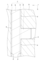
- FIG. 3 is a partially enlarged view of FIG. 2 .
- FIG. 4 is a cross-sectional view of an electrolysis cell 100 according to the first modification.
- Fig. 1 is a plan view of an electrolytic cell 1 according to an embodiment.
- Fig. 2 is a cross-sectional view taken along line AA in Fig. 1.
- the electrolytic cell 1 is an example of the "electrochemical cell" according to the present invention.
- the electrolytic cell 1 is formed in a plate shape extending in the X-axis and Y-axis directions.
- the electrolytic cell 1 is formed in a rectangular shape extending in the Y-axis direction when viewed in a plan view from the Z-axis direction perpendicular to the X-axis and Y-axis directions.
- the planar shape of the electrolytic cell 1 is not particularly limited, and may be a polygon other than a rectangle, an ellipse, a circle, etc.
- the X-axis and Y-axis directions are the surface directions of the electrolytic cell 1, and the Z-axis direction is the thickness direction of the electrolytic cell 1.
- the electrolysis cell 1 includes a metal support 10, a cell body 20, and a flow path member 30.
- the metal support 10 supports the cell main body 20.
- the metal support 10 is formed in a plate shape.
- the metal support 10 may be in the shape of a flat plate or a curved plate.
- the metal support 10 only needs to be able to support the electrolysis cell 1, and there are no particular limitations on its thickness, but it can be, for example, 0.1 mm or more and 2.0 mm or less.
- the metal support 10 has a plurality of communication holes 11, a first main surface 12, and a second main surface 13.
- Each communication hole 11 penetrates the metal support 10 from the first main surface 12 to the second main surface 13. Each communication hole 11 opens to the first main surface 12 and the second main surface 13. The opening of each communication hole 11 on the first main surface 12 side is covered by the hydrogen electrode layer 6. The opening of each communication hole 11 on the second main surface 13 side is connected to a flow path 30a described later.
- Each communication hole 11 can be formed by mechanical processing (e.g., punching), laser processing, or chemical processing (e.g., etching).
- each communication hole 11 is formed linearly along the Z-axis direction.
- each communication hole 11 may be inclined with respect to the Z-axis direction, and may not be linear.
- the communication holes 11 may be connected to each other.
- the first main surface 12 is provided on the opposite side to the second main surface 13.
- the cell main body 20 is disposed on the first main surface 12.
- the flow path member 30 is bonded to the second main surface 13.
- the metal support 10 is made of a metal material.
- the metal support 10 is made of an alloy material containing Cr (chromium).
- Examples of such metal materials include Fe-Cr alloy steel (stainless steel, etc.) and Ni-Cr alloy steel.
- Cr content in the metal support 10 can be 4% by mass or more and 30% by mass or less.
- the metal support 10 may contain Ti (titanium) and Zr (zirconium).
- the Ti content in the metal support 10 is not particularly limited, but may be 0.01 mol% or more and 1.0 mol% or less.
- the Al content in the metal support 10 is not particularly limited, but may be 0.01 mol% or more and 0.4 mol% or less.
- the metal support 10 may contain Ti as TiO2 (titania) and Zr as ZrO2 (zirconia).
- the metal support 10 may have an oxide film on its surface that is formed by oxidation of the constituent elements of the metal support 10.
- a typical example of the oxide film is a chromium oxide film.
- the chromium oxide film covers at least a portion of the surface of the metal support 10.
- the chromium oxide film may also cover at least a portion of the inner wall surface of each communication hole 11.
- the cell body 20 is disposed on the metal support 10.
- the cell body 20 is supported by the metal support 10.
- the cell body 20 has a hydrogen electrode layer 6 (cathode), an electrolyte layer 7, a reaction prevention layer 8, and an oxygen electrode layer 9 (anode).
- the hydrogen electrode layer 6, electrolyte layer 7, reaction prevention layer 8, and oxygen electrode layer 9 are stacked in this order in the Z-axis direction from the metal support 10 side.
- the hydrogen electrode layer 6, electrolyte layer 7, and oxygen electrode layer 9 are required components, while the reaction prevention layer 8 is optional.
- the hydrogen electrode layer 6 is an example of a "first electrode layer” according to the present invention.
- the hydrogen electrode layer 6 is disposed between the metal support 10 and the electrolyte layer 7.
- the hydrogen electrode layer 6 is formed on the first main surface 12 of the metal support 10. In this embodiment, a portion of the hydrogen electrode layer 6 is disposed inside each of the communication holes 11 of the metal support 10. A detailed configuration of the hydrogen electrode layer 6 will be described later.
- a source gas is supplied to the hydrogen electrode layer 6 through each of the communication holes 11.
- the source gas contains at least H2O .
- the hydrogen electrode layer 6 produces H 2 from the source gas in accordance with the electrochemical reaction of water electrolysis shown in the following formula (1).
- Hydrogen electrode layer 6 H 2 O+2e ⁇ ⁇ H 2 +O 2 ⁇ (1)
- the hydrogen electrode layer 6 produces H 2 , CO, and O 2 ⁇ from the source gas in accordance with the co-electrochemical reactions shown in the following formulas (2), (3), and (4).
- Hydrogen electrode layer 6 CO 2 + H 2 O + 4e ⁇ ⁇ CO + H 2 + 2O 2 ⁇ (2) Electrochemical reaction of H 2 O: H 2 O + 2e ⁇ ⁇ H 2 + O 2 ⁇ (3) Electrochemical reaction of CO2 : CO2 + 2e- ⁇ CO + O2 -... (4)
- the hydrogen electrode layer 6 is a porous body with electronic conductivity.
- the hydrogen electrode layer 6 contains nickel (Ni) and an oxide ion conductive material.
- Ni functions as an electronic conductor. In the case of co-electrolysis, Ni also functions as a thermal catalyst to promote the thermal reaction between the generated H2 and the CO2 contained in the feed gas to maintain an appropriate gas composition for methanation, reverse water gas shift reaction, etc.
- Ni exists in the form of nickel oxide (NiO) in an oxidizing atmosphere and in the form of metallic Ni in a reducing atmosphere.
- the hydrogen electrode layer 6 is exposed to an oxidizing atmosphere when the electrolytic cell 1 is stopped, and is exposed to a reducing atmosphere when the electrolytic cell 1 is in operation and during the reduction treatment carried out before the operation of the electrolytic cell 1.
- the hydrogen electrode layer 6 expands/contracts with the oxidation/reduction of Ni.
- oxide ion conductive materials examples include YSZ, CSZ, ScSZ, GDC, SDC, (La,Sr)(Cr,Mn) O3 , (La,Sr) TiO3 , Sr2 (Fe,Mo) 2O6 , ( La ,Sr) VO3 , (La,Sr) FeO3 , LDC (lanthanum doped ceria), LSGM (lanthanum gallate), and mixed materials of two or more of these.
- the thickness of the hydrogen electrode layer 6 is not particularly limited, but can be, for example, 1 ⁇ m or more and 100 ⁇ m or less.
- the method for forming the hydrogen electrode layer 6 is not particularly limited, and may be a sintering method, a spray coating method (thermal spraying, aerosol deposition, aerosol gas deposition, powder jet deposition, particle jet deposition, cold spray, etc.), a PVD method (sputtering, pulsed laser deposition, etc.), a CVD method, etc.
- the electrolyte layer 7 is disposed between the hydrogen electrode layer 6 and the oxygen electrode layer 9.
- the reaction prevention layer 8 is disposed between the electrolyte layer 7 and the oxygen electrode layer 9, so that the electrolyte layer 7 is sandwiched between the hydrogen electrode layer 6 and the reaction prevention layer 8.
- the electrolyte layer 7 covers the hydrogen electrode layer 6 and also covers the area of the first main surface 12 of the metal support 10 that is exposed from the hydrogen electrode layer 6.
- the electrolyte layer 7 transfers O 2- generated in the hydrogen electrode layer 6 to the oxygen electrode layer 9.
- the electrolyte layer 7 is made of a dense material having oxide ion conductivity.
- the electrolyte layer 7 can be made of, for example, YSZ (yttria-stabilized zirconia, e.g., 8YSZ), GDC (gadolinium-doped ceria), ScSZ (scandia-stabilized zirconia), SDC (samarium-doped ceria), LSGM (lanthanum gallate), or the like.
- the porosity of the electrolyte layer 7 is not particularly limited, but can be, for example, 0.1% to 7%.
- the thickness of the electrolyte layer 7 is not particularly limited, but can be, for example, 1 ⁇ m to 100 ⁇ m.
- the method for forming the electrolyte layer 7 is not particularly limited, and methods such as baking, spray coating, PVD, and CVD can be used.
- reaction prevention layer 8 The reaction prevention layer 8 is disposed between the electrolyte layer 7 and the oxygen electrode layer 9. The reaction prevention layer 8 is disposed on the opposite side of the electrolyte layer 7 to the hydrogen electrode layer 6. The reaction prevention layer 8 prevents the constituent elements of the electrolyte layer 7 from reacting with the constituent elements of the oxygen electrode layer 9 to form a layer with high electrical resistance.
- the reaction prevention layer 8 is made of an oxide ion conductive material.
- the reaction prevention layer 8 can be made of GDC, SDC, etc.
- the porosity of the reaction prevention layer 8 is not particularly limited, but can be, for example, 0.1% to 50%.
- the thickness of the reaction prevention layer 8 is not particularly limited, but can be, for example, 1 ⁇ m to 50 ⁇ m.
- the method for forming the reaction prevention layer 8 is not particularly limited, and a baking method, a spray coating method, a PVD method, a CVD method, etc. can be used.
- the oxygen electrode layer 9 is an example of a "second electrode layer” according to the present invention.
- the oxygen electrode layer 9 is disposed on the opposite side of the hydrogen electrode layer 6 with respect to the electrolyte layer 7.
- the reaction prevention layer 8 is disposed between the electrolyte layer 7 and the oxygen electrode layer 9, and therefore the oxygen electrode layer 9 is connected to the reaction prevention layer 8. If the reaction prevention layer 8 is not disposed between the electrolyte layer 7 and the oxygen electrode layer 9, the oxygen electrode layer 9 would be connected to the electrolyte layer 7.
- the oxygen electrode layer 9 produces O 2 from O 2 ⁇ transferred from the hydrogen electrode layer 6 via the electrolyte layer 7 in accordance with the chemical reaction of the following formula (2).
- Oxygen electrode layer 9 2O 2 ⁇ ⁇ O 2 +4e ⁇ (2)
- the oxygen electrode layer 9 is made of a porous material having oxide ion conductivity and electron conductivity, and may be made of a composite material of one or more of (La,Sr)(Co,Fe) O3 , (La,Sr) FeO3 , La(Ni,Fe) O3 , (La,Sr) CoO3 , and (Sm,Sr) CoO3 and an oxide ion conductive material (such as GDC).
- the porosity of the oxygen electrode layer 9 is not particularly limited, but can be, for example, 20% or more and 60% or less.
- the thickness of the oxygen electrode layer 9 is not particularly limited, but can be, for example, 1 ⁇ m or more and 100 ⁇ m or less.
- the method for forming the oxygen electrode layer 9 is not particularly limited, and a firing method, a spray coating method, a PVD method, a CVD method, etc. can be used.
- the flow path member 30 is joined to the second main surface 13 of the metal support 10.
- the flow path member 30 forms a flow path 30a between itself and the metal support 10.
- a source gas is supplied to the flow path 30a.
- the source gas supplied to the flow path 30a is supplied to the hydrogen electrode layer 6 of the cell main body 20 through each communication hole 11 of the metal support 10.
- the flow path member 30 can be made of, for example, an alloy material.
- the flow path member 30 may be made of the same material as the metal support 10. In this case, the flow path member 30 may be substantially integral with the metal support 10.
- the flow path member 30 has a frame body 31 and an interconnector 32.
- the frame body 31 is an annular member that surrounds the side of the flow path 30a.
- the frame body 31 is joined to the second main surface 13 of the metal support body 10.
- the interconnector 32 is a plate-shaped member for electrically connecting an external power source or another electrolysis cell in series with the electrolysis cell 1.
- the interconnector 32 is joined to the frame body 31.
- the frame body 31 and the interconnector 32 are separate members, but the frame body 31 and the interconnector 32 may be an integrated member.
- FIG. 3 is a partially enlarged view of Fig. 2. As shown in Fig. 3, the hydrogen electrode layer 6 has a first region 61, a second region 62, a third region 63, and a fourth region 64.
- the first region 61 is a region of the hydrogen electrode layer 6 within 5 ⁇ m in the Z-axis direction (thickness direction) from the first surface S1 that contacts the metal support 10.
- the second region 62 is a region of the hydrogen electrode layer 6 within 5 ⁇ m in the Z-axis direction from the second surface S2 that contacts the electrolyte layer 7.
- the third region 63 is a region of the hydrogen electrode layer 6 between the first region 61 and the second region 62.
- the fourth region 64 is a region of the hydrogen electrode layer 6 that is disposed inside the communication hole 11 of the metal support 10. The fourth region 64 is engaged with the communication hole 11, thereby exerting an anchor effect on the metal support 10.
- the first to third regions 61 to 63 are required components, while the fourth region 64 is optional.
- the fourth region 64 only needs to be present inside at least one of the multiple communication holes 11 formed in the metal support 10. Therefore, the number of fourth regions 64 may be the same as the number of communication holes 11, or may be less than the number of communication holes 11.
- the first surface S1 of the hydrogen electrode layer 6 contacts the first main surface 12 of the metal support 10.
- an approximation line of the first surface S1 obtained by the least squares method is used in a cross section along the Z-axis direction.
- the region of the surface of the hydrogen electrode layer 6 that contacts the first main surface 12 of the metal support 10 is approximated as a straight line by the least squares method, and the obtained approximation line is regarded as the first surface S1 of the hydrogen electrode layer 6.
- the region of the surface of the hydrogen electrode layer 6 that contacts the first main surface 12 of the metal support 10 does not include the inner surface of the communication hole 11 of the metal support 10.
- the second surface S2 of the hydrogen electrode layer 6 contacts the hydrogen electrode layer side surface S3 of the electrolyte layer 7.
- an approximation line of the second surface S2 obtained by the least squares method is used in a cross section along the Z-axis direction. Specifically, the region of the surface of the hydrogen electrode layer 6 that contacts the hydrogen electrode layer side surface S3 of the electrolyte layer 7 is approximated as a straight line by the least squares method, and the obtained approximation line is regarded as the second surface S2 of the hydrogen electrode layer 6.
- Each of the first to fourth regions 61 to 64 contains Ni and an oxide ion conductive material.
- the Ni content in the first region 61 is lower than the Ni content in the third region 63. This reduces the expansion/contraction of the first region 61 caused by the redox cycle, and prevents the hydrogen electrode layer 6 from peeling off from the metal support 10. Furthermore, the third region 63 can improve electronic conductivity and catalytic performance. This makes it possible to both prevent peeling of the hydrogen electrode layer 6 and maintain electrode performance.
- the Ni content in the second region 62 is preferably lower than the Ni content in the third region 63. This allows the expansion/contraction to be reduced not only in the first region 61 but also in the second region 62, making it possible to suppress the increase in internal resistance caused by the deterioration of adhesion between the hydrogen electrode layer 6 and the electrolyte layer 7 when oxidation-reduction cycles are repeated, while maintaining electrode performance.
- the Ni content in the second region 62 is preferably lower than the Ni content in the first region 61. This makes the amount of reduction shrinkage in the second region 62 smaller than the amount of reduction shrinkage in the first region 61, improving the shrinkage balance in the entire hydrogen electrode layer 6. As a result, the hydrogen electrode layer 6 is prevented from warping in a protruding shape toward the metal support 10, and the hydrogen electrode layer 6 (particularly the outer periphery of the hydrogen electrode layer 6 in the surface direction) is prevented from peeling off from the metal support 10.
- the Ni content in the fourth region 64 is preferably lower than the Ni content in the third region 63. This reduces the expansion/contraction of the fourth region 64 caused by the redox cycle, thereby suppressing changes in the shape of the fourth region 64. As a result, the anchoring effect of the fourth region 64 can be maintained.
- Ni content in the first to fourth regions 61 to 64 is calculated using the same method, as described below.
- the Ni content in the first region 61 is calculated by measuring the Ni content at five locations (randomly selected) spaced apart in the plane direction in the center of the thickness direction of the first region 61 in a cross section of the hydrogen electrode layer 6 along the Z-axis direction, and averaging the five measured values obtained.
- the value of the Ni content in the first region 61 is not particularly limited, but can be 25 mol% or more and 45 mol% or less.
- the Ni content in the second region 62 is calculated by measuring the Ni content at five locations (randomly selected) spaced apart in the plane direction in the center of the thickness direction of the second region 62 in a cross section of the hydrogen electrode layer 6 along the Z-axis direction, and averaging the five measured values obtained.
- the value of the Ni content in the second region 62 is not particularly limited, but can be 20 mol% or more and 45 mol% or less.
- the Ni content in the third region 63 is calculated by measuring the Ni content at four locations in a cross section of the hydrogen electrode layer 6 along the Z-axis direction, which divides the third region 63 into five equal parts in the Z-axis direction, and averaging the four measured values.
- the value of the Ni content in the third region 63 is not particularly limited, but can be 30 mol% or more and 50 mol% or less.
- the Ni content in the fourth region 64 is calculated by measuring the Ni content at five locations (randomly selected) spaced apart in the plane direction in the center of the thickness direction of the fourth region 64 in a cross section of the hydrogen electrode layer 6 along the Z-axis direction, and averaging the five measured values obtained.
- the value of the Ni content in the fourth region 64 is not particularly limited, but can be 20 mol% or more and 45 mol% or less.
- the Ni content is calculated using the following method. First, a Ni composition mapping image on the cross section is obtained at 5,000 to 10,000 times magnification using an SEM device (FE-SEM JSM-7900F, manufactured by JEOL Ltd.) and an EDS device (JED-2300) attached to the SEM device. Next, Ni particle portions are identified in the Ni composition mapping image by performing binarization processing using image analysis using image analysis software Image-Pro manufactured by MEDIACYBERNETICS. The Ni content is then calculated by dividing the total area of the Ni particle portions by the total area of the backscattered electron image.
- SEM device FE-SEM JSM-7900F, manufactured by JEOL Ltd.
- JED-2300 EDS device
- the first main surface 12 of the metal support 10 is not planar (for example, if the metal support 10 is made of a porous metal), it is difficult to identify the first surface S1 of the hydrogen electrode layer 6 using the first main surface 12 of the metal support 10.
- Figure 4 is a cross section of the electrolysis cell 100 along the Z-axis direction (thickness direction).
- the electrolysis cell 100 has the same configuration as the electrolysis cell 1 according to the above embodiment, except that the metal support 110 is made of a porous metal.
- the metal support 110 has metal particles 111 connected in a three-dimensional mesh pattern and a plurality of interconnected communication holes 112.
- the first main surface 113 of the metal support 10 has projections and recesses formed along the outer edges of the metal particles 111.
- the second surface S2 of the hydrogen electrode layer 6 is identified by the hydrogen electrode layer side surface S3 of the electrolyte layer 7.
- the intersection P where it intersects with the metal particles 111 is identified.
- the intersection P is identified for each cluster of metal particles 111 that are separated on the cross section.
- the metal particles 111 are divided into three clusters, so intersections P1 to P3 are identified in Figure 4.
- the lines sequentially connecting the intersections P1 to P3 with straight lines are defined as the first surface S1 of the hydrogen electrode layer 6.
- the first surface S1 of the hydrogen electrode layer 6 can be identified based on the hydrogen electrode layer side surface S3 of the electrolyte layer 7.
- the hydrogen electrode layer 6 has the fourth region 64 , but it is not essential that the hydrogen electrode layer 6 has the fourth region 64 .
- the electrolysis cell 1 has been described as an example of an electrochemical cell, but the electrochemical cell is not limited to the electrolysis cell.
- An electrochemical cell is a general term for an element in which a pair of electrodes are arranged so that an electromotive force is generated from an overall oxidation-reduction reaction in order to convert electrical energy into chemical energy, and an element for converting chemical energy into electrical energy. Therefore, the electrochemical cell includes, for example, a fuel cell that uses oxide ions or protons as a carrier.
- Comparative Example 1 An electrolytic cell according to Comparative Example 1 was prepared as follows.
- a slurry for the hydrogen electrode layer was prepared by mixing GDC powder, NiO powder, butyral resin, polymethyl methacrylate beads as a pore-forming material, a plasticizer, a dispersant, and a solvent.
- the slurry for the hydrogen electrode layer was then printed on the first main surface of the metal support by the doctor blade method to form a hydrogen electrode layer compact.
- a slurry for the electrolyte layer was prepared by mixing YSZ powder, butyral resin, plasticizer, dispersant, and solvent.
- the electrolyte slurry was then printed using a doctor blade method to cover the green body of the hydrogen electrode layer, forming a green body for the electrolyte layer.
- a slurry for the reaction prevention layer was prepared by mixing GDC powder, polyvinyl alcohol, and a solvent.
- the slurry for the reaction prevention layer was then printed on the electrolyte layer compact by the doctor blade method to form a reaction prevention layer compact.
- the molded bodies of the hydrogen electrode layer, electrolyte layer, and reaction prevention layer arranged in sequence on the metal support were fired in air (1050°C, 1 hour) to form the hydrogen electrode layer, electrolyte layer, and reaction prevention layer.
- a slurry for the oxygen electrode layer was prepared by mixing (La, Sr) (Co, Fe) O3 powder, polyvinyl alcohol, and a solvent.
- the slurry for the oxygen electrode layer was then printed on the reaction prevention layer by a doctor blade method to form a compact for the oxygen electrode layer.
- the oxygen electrode layer compact was sintered in air (1000°C, 1 hour) to form the oxygen electrode.
- the slurry for the first region was prepared by mixing GDC powder, NiO powder, butyral resin, polymethyl methacrylate beads as a pore-forming material, a plasticizer, a dispersant, and a solvent.
- the Ni content in the first region was changed as shown in Table 1 by adjusting the amount of NiO powder added.
- the slurry for the first region was printed on the first main surface of the metal support by the doctor blade method to form a molded body of the first region of the hydrogen electrode layer.
- a slurry for the third region was prepared by mixing GDC powder, NiO powder, butyral resin, polymethyl methacrylate beads as a pore-forming material, a plasticizer, a dispersant, and a solvent.
- the Ni content in the third region was changed as shown in Table 1 by adjusting the amount of NiO powder added.
- the slurry for the third region was printed on the molded body of the first region by the doctor blade method to form a molded body of the third region of the hydrogen electrode layer.
- a slurry for the second region was prepared by mixing GDC powder, NiO powder, butyral resin, polymethylmethacrylate beads as a pore-forming material, a plasticizer, a dispersant, and a solvent.
- the Ni content in the second region was changed as shown in Table 1 by adjusting the amount of NiO powder added.
- the slurry for the second region was printed on the molded body of the third region by the doctor blade method to form a molded body of the second region of the hydrogen electrode layer.
- one oxidation-reduction cycle was carried out in which a process of supplying a mixed gas of water vapor and hydrogen (mixing ratio 90:10) to the hydrogen electrode layer for 10 hours, a process of supplying a mixed gas of water vapor and hydrogen (mixing ratio 98:2) to the hydrogen electrode layer for 10 hours, and a process of supplying a mixed gas of water vapor and hydrogen (mixing ratio 90:10) to the hydrogen electrode layer for 10 hours were carried out.
- Examples 1 to 9 in which the Ni content in the first region of the hydrogen electrode layer was lower than the Ni content in the third region, interfacial peeling in the initial evaluation was suppressed compared to Comparative Example 1. This result was obtained because the expansion/contraction of the first region caused by the redox cycle was reduced. Furthermore, in Examples 1 to 9, the electrolytic cell performance in the initial evaluation was improved compared to Comparative Example 2. This result was obtained because the electronic conductivity and catalytic performance in the third region were improved. In this way, Examples 1 to 9 were able to achieve both suppression of peeling and maintenance of electrode performance.
- Electrolysis cell 10
- Metal support 11 Through hole 12
- First main surface 13
- Second main surface 20
- Cell body 6
- Hydrogen electrode layer 61
- First region 62
- Second region 63
- Third region 64
- Fourth region 7
- Electrolyte layer 8
- Reaction prevention layer 9
- Oxygen electrode layer 30
- Flow path member 30a Flow path
Landscapes
- Chemical & Material Sciences (AREA)
- Electrochemistry (AREA)
- Chemical Kinetics & Catalysis (AREA)
- Engineering & Computer Science (AREA)
- Materials Engineering (AREA)
- General Chemical & Material Sciences (AREA)
- Metallurgy (AREA)
- Organic Chemistry (AREA)
- Sustainable Energy (AREA)
- Sustainable Development (AREA)
- Manufacturing & Machinery (AREA)
- Life Sciences & Earth Sciences (AREA)
- Inorganic Chemistry (AREA)
- Electrolytic Production Of Non-Metals, Compounds, Apparatuses Therefor (AREA)
Abstract
電解セル(1)は、金属支持体(10)と、セル本体部(20)とを備える。セル本体部(20)は、金属支持体(10)の第1主面(12)に形成された各連通孔(11)を覆う水素極層(6)を有する。水素極層(6)は、金属支持体(10)と接触する第1面(S1)から厚み方向に5μm以内の第1領域(61)と、電解質層(7)と接触する第2面(S2)から厚み方向に5μm以内の第2領域(62)と、第1領域(61)及び第2領域(62)の間の第3領域(63)とを有する。第1領域(61)、第2領域(62)、及び第3領域(63)それぞれは、ニッケルと酸化物イオン伝導性材料とを含有する。第1領域(61)におけるニッケルの含有率は、第3領域(63)におけるニッケルの含有率より低い。
Description
本発明は、電気化学セルに関する。
従来、金属支持体上に配置されたセル本体部を備える電気化学セル(電解セル、燃料電池など)が知られている(例えば、特許文献1参照)。
金属支持体は、主面に形成された複数の連通孔を有する。セル本体部は、金属支持体の主面上に形成され、複数の連通孔を覆う第1電極層と、第2電極層と、第1電極層及び第2電極層の間に配置される電解質層とを有する。第1電極層は、導電性を付与するための金属としてニッケルを含有する。第1電極層が含有するニッケルは、酸化雰囲気では酸化ニッケルとなり、還元雰囲気では金属ニッケルとなる。
上述した電気化学セルでは、酸化還元サイクルに起因して第1電極層が膨張/収縮する。具体的には、電気化学セルの運転前に第1電極層が還元処理されると、酸化ニッケルが金属ニッケルとなって第1電極層は収縮し、電気化学セルの運転が停止して第1電極層が還元雰囲気から酸化雰囲気に変わると、金属ニッケルが酸化ニッケルとなって第1電極層は膨張する。
このように、酸化還元サイクルに起因して第1電極層が膨張/収縮すると、第1電極層が金属支持体から剥離するおそれがある。
本発明の課題は、第1電極層が金属支持体から剥離することを抑制可能な電気化学セルを提供することにある。
本発明の第1の側面に係る電気化学セルは、主面に形成された複数の連通孔を有する金属支持体と、主面上に形成され、複数の連通孔を覆う第1電極層と、第2電極層と、第1電極層及び第2電極層の間に配置される電解質層とを有するセル本体部とを備える。第1電極層は、金属支持体と接触する第1面から厚み方向に5μm以内の第1領域と、電解質層と接触する第2面から厚み方向に5μm以内の第2領域と、第1領域及び第2領域の間の第3領域とを有する。第1領域、第2領域、及び第3領域それぞれは、ニッケルと酸化物イオン伝導性材料とを含有する。第1領域におけるニッケルの含有率は、第3領域におけるニッケルの含有率より低い。
本発明の第2の側面に係る電気化学セルは、上記第1の側面に係り、第2領域におけるニッケルの含有率は、第3領域におけるニッケルの含有率より低い。
本発明の第3の側面に係る電気化学セルは、上記第1又は第2の側面に係り、第2領域におけるニッケルの含有率は、第1領域におけるニッケルの含有率より低い。
本発明の第4の側面に係る電気化学セルは、上記第1乃至第4の側面に係り、第1電極層は、複数の連通孔のうち少なくとも1つの内側に配置される第4領域を有する。第4領域は、ニッケルと酸化物イオン伝導性材料とを含有する。第4領域におけるニッケルの含有率は、第3領域におけるニッケルの含有率より低い。
本発明によれば、第1電極層が金属支持体から剥離することを抑制可能な電気化学セルを提供することができる。
(電解セル1)
図1は、実施形態に係る電解セル1の平面図である。図2は、図1のA-A断面図である。電解セル1は、本発明に係る「電気化学セル」の一例である。
図1は、実施形態に係る電解セル1の平面図である。図2は、図1のA-A断面図である。電解セル1は、本発明に係る「電気化学セル」の一例である。
電解セル1は、X軸方向及びY軸方向に広がる板状に形成される。本実施形態において、電解セル1は、X軸方向及びY軸方向に垂直なZ軸方向から平面視した場合、Y軸方向に延びる長方形に形成される。ただし、電解セル1の平面形状は特に限られず、長方形以外の多角形、楕円形、円形などであってもよい。なお、X軸方向及びY軸方向それぞれは電解セル1の面方向であり、Z軸方向は電解セル1の厚み方向である。
図2に示すように、電解セル1は、金属支持体10、セル本体部20、及び流路部材30を備える。
[金属支持体10]
金属支持体10は、セル本体部20を支持する。金属支持体10は、板状に形成される。金属支持体10は、平板状であってもよいし、曲板状であってもよい。
金属支持体10は、セル本体部20を支持する。金属支持体10は、板状に形成される。金属支持体10は、平板状であってもよいし、曲板状であってもよい。
金属支持体10は電解セル1を支持できればよく、その厚みは特に制限されないが、例えば0.1mm以上2.0mm以下とすることができる。
図2に示すように、金属支持体10は、複数の連通孔11、第1主面12及び第2主面13を有する。
各連通孔11は、第1主面12から第2主面13まで金属支持体10を貫通する。各連通孔11は、第1主面12及び第2主面13それぞれに開口する。各連通孔11の第1主面12側の開口は、水素極層6によって覆われる。各連通孔11の第2主面13側の開口は、後述する流路30aに繋がる。
各連通孔11は、機械加工(例えば、パンチング加工)、レーザ加工、或いは、化学加工(例えば、エッチング加工)などによって形成することができる。
本実施形態において、各連通孔11は、Z軸方向に沿って直線状に形成される。ただし、各連通孔11は、Z軸方向に対して傾斜していてもよいし、直線状でなくてもよい。また、連通孔11どうしが互いに連なっていてもよい。
第1主面12は、第2主面13の反対側に設けられる。第1主面12には、セル本体部20が配置される。第2主面13には、流路部材30が接合される。
金属支持体10は、金属材料によって構成される。例えば、金属支持体10は、Cr(クロム)を含有する合金材料によって構成される。このような金属材料としては、Fe-Cr系合金鋼(ステンレス鋼など)やNi-Cr系合金鋼などが挙げられる。金属支持体10におけるCrの含有率は特に制限されないが、4質量%以上30質量%以下とすることができる。
金属支持体10は、Ti(チタン)やZr(ジルコニウム)を含有していてもよい。金属支持体10におけるTiの含有率は特に制限されないが、0.01mol%以上1.0mol%以下とすることができる。金属支持体10におけるAlの含有率は特に制限されないが、0.01mol%以上0.4mol%以下とすることができる。金属支持体10は、TiをTiO2(チタニア)として含有していてもよいし、ZrをZrO2(ジルコニア)として含有していてもよい。
金属支持体10は、金属支持体10の構成元素が酸化することによって形成される酸化皮膜を表面に有していてよい。酸化膜としては、例えば酸化クロム膜が代表的である。酸化クロム膜は、金属支持体10の表面の少なくとも一部を覆う。また、酸化クロム膜は、各連通孔11の内壁面の少なくとも一部を覆っていてもよい。
[セル本体部20]
セル本体部20は、金属支持体10上に配置される。セル本体部20は、金属支持体10によって支持される。セル本体部20は、水素極層6(カソード)、電解質層7、反応防止層8、及び酸素極層9(アノード)を有する。
セル本体部20は、金属支持体10上に配置される。セル本体部20は、金属支持体10によって支持される。セル本体部20は、水素極層6(カソード)、電解質層7、反応防止層8、及び酸素極層9(アノード)を有する。
水素極層6、電解質層7、反応防止層8、及び酸素極層9は、Z軸方向において、この順で金属支持体10側から積層されている。水素極層6、電解質層7、及び酸素極層9は必須の構成であり、反応防止層8は任意の構成である。
[水素極層6]
水素極層6は、本発明に係る「第1電極層」の一例である。水素極層6は、金属支持体10及び電解質層7の間に配置される。水素極層6は、金属支持体10の第1主面12上に形成される。本実施形態では、水素極層6の一部が、金属支持体10の各連通孔11の内側に配置されている。水素極層6の詳細な構成については後述する。
水素極層6は、本発明に係る「第1電極層」の一例である。水素極層6は、金属支持体10及び電解質層7の間に配置される。水素極層6は、金属支持体10の第1主面12上に形成される。本実施形態では、水素極層6の一部が、金属支持体10の各連通孔11の内側に配置されている。水素極層6の詳細な構成については後述する。
水素極層6には、各連通孔11を介して原料ガスが供給される。原料ガスは、原料ガスは少なくともH2Oを含む。
原料ガスがH2Oのみを含む場合、水素極層6は、下記(1)式に示す水電解の電気化学反応に従って、原料ガスからH2を生成する。
・水素極層6:H2O+2e-→H2+O2-・・・(1)
原料ガスがH2Oに加えてCO2を含む場合、水素極層6は、下記(2)、(3)、(4)式に示す共電解の電気化学反応に従って、原料ガスからH2、CO及びO2-を生成する。
・水素極層6:CO2+H2O+4e-→CO+H2+2O2-・・・(2)
・H2Oの電気化学反応:H2O+2e-→H2+O2-・・・(3)
・CO2の電気化学反応:CO2+2e-→CO+O2-・・・(4)
・H2Oの電気化学反応:H2O+2e-→H2+O2-・・・(3)
・CO2の電気化学反応:CO2+2e-→CO+O2-・・・(4)
水素極層6は、電子伝導性を有する多孔体である。水素極層6は、ニッケル(Ni)と酸化物イオン伝導性材料とを含有する。
Niは、電子伝導物質として機能する。共電解の場合、Niは、生成されるH2と原料ガスに含まれるCO2との熱的反応を促進してメタネーションや逆水性ガスシフト反応などに適切なガス組成を維持する熱触媒としても機能する。
Niは、酸化雰囲気において酸化ニッケル(NiO)の状態で存在し、還元雰囲気において金属Niの状態で存在する。水素極層6は、電解セル1の停止中において酸化雰囲気に曝され、電解セル1の運転中、及び、電解セル1の運転前に実施される還元処理中において還元雰囲気に曝される。水素極層6は、Niの酸化/還元に伴って膨張/収縮する。
酸化物イオン伝導性材料としては、YSZ、CSZ、ScSZ、GDC、SDC、(La,Sr)(Cr,Mn)O3、(La,Sr)TiO3、Sr2(Fe,Mo)2O6、(La,Sr)VO3、(La,Sr)FeO3、LDC(ランタンドープセリア)、LSGM(ランタンガレート)及びこれらのうち2つ以上を組み合わせた混合材料などを用いることができる。
水素極層6の厚みは特に制限されないが、例えば1μm以上100μm以下とすることができる。
水素極層6の形成方法は特に制限されず、焼成法、スプレーコーティング法(溶射法、エアロゾルデポジション法、エアロゾルガスデポジッション法、パウダージェットデポジッション法、パーティクルジェットデポジション法、コールドスプレー法など)、PVD法(スパッタリング法、パルスレーザーデポジション法など)、CVD法などを用いることができる。
[電解質層7]
電解質層7は、水素極層6及び酸素極層9の間に配置される。本実施形態では、電解質層7及び酸素極層9の間に反応防止層8が配置されているので、電解質層7は、水素極層6及び反応防止層8の間に挟まれている。
電解質層7は、水素極層6及び酸素極層9の間に配置される。本実施形態では、電解質層7及び酸素極層9の間に反応防止層8が配置されているので、電解質層7は、水素極層6及び反応防止層8の間に挟まれている。
電解質層7は、水素極層6を覆うとともに、金属支持体10の第1主面12のうち水素極層6から露出する領域を覆う。
電解質層7は、水素極層6において生成されたO2-を酸素極層9側に伝達させる。電解質層7は、酸化物イオン伝導性を有する緻密質材料によって構成される。電解質層7は、例えば、YSZ(イットリア安定化ジルコニア、例えば8YSZ)、GDC(ガドリニウムドープセリア)、ScSZ(スカンジア安定化ジルコニア)、SDC(サマリウム固溶セリア)、LSGM(ランタンガレート)などによって構成することができる。
電解質層7の気孔率は特に制限されないが、例えば0.1%以上7%以下とすることができる。電解質層7の厚みは特に制限されないが、例えば1μm以上100μm以下とすることができる。
電解質層7の形成方法は特に制限されず、焼成法、スプレーコーティング法、PVD法、CVD法などを用いることができる。
[反応防止層8]
反応防止層8は、電解質層7及び酸素極層9の間に配置される。反応防止層8は、電解質層7を基準として水素極層6の反対側に配置される。反応防止層8は、電解質層7の構成元素が酸素極層9の構成元素と反応して電気抵抗の大きい層が形成されることを抑制する。
反応防止層8は、電解質層7及び酸素極層9の間に配置される。反応防止層8は、電解質層7を基準として水素極層6の反対側に配置される。反応防止層8は、電解質層7の構成元素が酸素極層9の構成元素と反応して電気抵抗の大きい層が形成されることを抑制する。
反応防止層8は、酸化物イオン伝導性材料によって構成される。反応防止層8は、GDC、SDCなどによって構成することができる。
反応防止層8の気孔率は特に制限されないが、例えば0.1%以上50%以下とすることができる。反応防止層8の厚みは特に制限されないが、例えば1μm以上50μm以下とすることができる。
反応防止層8の形成方法は特に制限されず、焼成法、スプレーコーティング法、PVD法、CVD法などを用いることができる。
[酸素極層9]
酸素極層9は、本発明に係る「第2電極層」の一例である。酸素極層9は、電解質層7を基準として水素極層6の反対側に配置される。本実施形態では、電解質層7及び酸素極層9の間に反応防止層8が配置されているので、酸素極層9は反応防止層8に接続される。電解質層7及び酸素極層9の間に反応防止層8が配置されない場合、酸素極層9は電解質層7に接続される。
酸素極層9は、本発明に係る「第2電極層」の一例である。酸素極層9は、電解質層7を基準として水素極層6の反対側に配置される。本実施形態では、電解質層7及び酸素極層9の間に反応防止層8が配置されているので、酸素極層9は反応防止層8に接続される。電解質層7及び酸素極層9の間に反応防止層8が配置されない場合、酸素極層9は電解質層7に接続される。
酸素極層9は、下記(2)式の化学反応に従って、水素極層6から電解質層7を介して伝達されるO2-からO2を生成する。
・酸素極層9:2O2-→O2+4e-・・・(2)
酸素極層9は、酸化物イオン伝導性及び電子伝導性を有する多孔質材料によって構成される。酸素極層9は、例えば(La,Sr)(Co,Fe)O3、(La,Sr)FeO3、La(Ni,Fe)O3、(La,Sr)CoO3、及び(Sm,Sr)CoO3のうち1つ以上と酸化物イオン伝導性材料(GDCなど)との複合材料によって構成することができる。
酸素極層9の気孔率は特に制限されないが、例えば20%以上60%以下とすることができる。酸素極層9の厚みは特に制限されないが、例えば1μm以上100μm以下とすることができる。
酸素極層9の形成方法は特に制限されず、焼成法、スプレーコーティング法、PVD法、CVD法などを用いることができる。
[流路部材30]
流路部材30は、金属支持体10の第2主面13に接合される。流路部材30は、金属支持体10との間に流路30aを形成する。流路30aには、原料ガスが供給される。流路30aに供給された原料ガスは、金属支持体10の各連通孔11を介して、セル本体部20の水素極層6に供給される。
流路部材30は、金属支持体10の第2主面13に接合される。流路部材30は、金属支持体10との間に流路30aを形成する。流路30aには、原料ガスが供給される。流路30aに供給された原料ガスは、金属支持体10の各連通孔11を介して、セル本体部20の水素極層6に供給される。
流路部材30は、例えば、合金材料によって構成することができる。流路部材30は、金属支持体10と同様の材料によって形成されていてもよい。この場合、流路部材30は、金属支持体10と実質的に一体であってもよい。
流路部材30は、枠体31及びインターコネクタ32を有する。枠体31は、流路30aの側方を取り囲む環状部材である。枠体31は、金属支持体10の第2主面13に接合される。インターコネクタ32は、外部電源又は他の電解セルを電解セル1と電気的に直列に接続するための板状部材である。インターコネクタ32は、枠体31に接合される。
本実施形態では、枠体31とインターコネクタ32が別部材となっているが、枠体31とインターコネクタ32は一体の部材であってもよい。
(水素極層6の構成)
図3は、図2の部分拡大図である。図3に示すように、水素極層6は、第1領域61、第2領域62、第3領域63、及び第4領域64を有する。
図3は、図2の部分拡大図である。図3に示すように、水素極層6は、第1領域61、第2領域62、第3領域63、及び第4領域64を有する。
第1領域61は、水素極層6のうち、金属支持体10と接触する第1面S1からZ軸方向(厚み方向)に5μm以内の領域である。第2領域62は、水素極層6のうち、電解質層7と接触する第2面S2からZ軸方向に5μm以内の領域である。第3領域63は、水素極層6のうち、第1領域61及び第2領域62の間の領域である。第4領域64は、水素極層6のうち、金属支持体10の連通孔11の内側に配置された領域である。第4領域64が連通孔11に係止されることによって、金属支持体10に対するアンカー効果を発揮する。
第1乃至第3領域61~63は必須の構成であり、第4領域64は任意の構成である。第4領域64は、金属支持体10に形成された複数の連通孔11のうち少なくとも1つの連通孔11の内側に存在していればよい。従って、第4領域64の数は、連通孔11の数と同じであってもよいし、連通孔11の数より少なくてもよい。
水素極層6の第1面S1は、金属支持体10の第1主面12と接触する。第1領域61を特定する際には、Z軸方向に沿った断面において、最小二乗法により求められる第1面S1の近似直線が用いられる。具体的には、水素極層6の表面のうち金属支持体10の第1主面12と接触する領域を最小二乗法で近似直線化し、得られた近似直線を水素極層6の第1面S1とする。なお、水素極層6の表面のうち金属支持体10の第1主面12と接触する領域には、金属支持体10の連通孔11の内周面は含まれない。
水素極層6の第2面S2は、電解質層7の水素極層側表面S3と接触する。第2領域62を特定する際には、Z軸方向に沿った断面において、最小二乗法により求められる第2面S2の近似直線が用いられる。具体的には、水素極層6の表面のうち電解質層7の水素極層側表面S3と接触する領域を最小二乗法で近似直線化し、得られた近似直線を水素極層6の第2面S2とする。
第1乃至第4領域61~64それぞれは、Niと酸化物イオン伝導性材料とを含有する。
第1領域61におけるNiの含有率は、第3領域63におけるNiの含有率より低い。これによって、酸化還元サイクルに起因する第1領域61の膨張/収縮を小さくすることができるため、水素極層6が金属支持体10から剥離することを抑制できる。また、第3領域63では電子伝導性及び触媒性能を向上させることができる。よって、水素極層6の剥離抑制と電極性能維持を両立させることができる。
第2領域62におけるNiの含有率は、第3領域63におけるNiの含有率より低いことが好ましい。これによって、第1領域61だけでなく第2領域62においても膨張/収縮を小さくすることができるため、酸化還元サイクルが繰り返された際の水素極層6と電解質層7との接着性悪化に伴う内部抵抗増大の抑制と、電極性能の維持とを両立させることができる。
第2領域62におけるNiの含有率は、第1領域61におけるNiの含有率より低いことが好ましい。これによって、第2領域62の還元収縮量が第1領域61の還元収縮量より小さくなるため、水素極層6全体における収縮バランスを向上させることができる。その結果、水素極層6が金属支持体10側に向かって突状に反ることを抑制できるため、水素極層6(特に、面方向における水素極層6の外周部)が金属支持体10から剥離することを抑制できる。
第4領域64におけるNiの含有率は、第3領域63におけるNiの含有率より低いことが好ましい。これによって、酸化還元サイクルに起因する第4領域64の膨張/収縮を小さくすることができるため、第4領域64の形状に変化が生じることを抑制できる。その結果、第4領域64によるアンカー効果を維持することができる。
第1乃至第4領域61~64におけるNiの含有率は、次に説明するように、それぞれ同様の手法によって算出される。
第1領域61におけるNiの含有率は、Z軸方向に沿った水素極層6の断面において、第1領域61の厚み方向中央部において面方向に離れた5カ所(無作為選択)でNiの含有率を測定し、得られた5つの測定値を算出平均することによって算出される。第1領域61におけるNiの含有率の値は特に限られないが、25mol%以上45mol%以下とすることができる。
第2領域62におけるNiの含有率は、Z軸方向に沿った水素極層6の断面において、第2領域62の厚み方向中央部において面方向に離れた5カ所(無作為選択)でNiの含有率を測定し、得られた5つの測定値を算出平均することによって算出される。第2領域62におけるNiの含有率の値は特に限られないが、20mol%以上45mol%以下とすることができる。
第3領域63におけるNiの含有率は、Z軸方向に沿った水素極層6の断面において、第3領域63をZ軸方向に5等分する4カ所でNiの含有率を測定し、得られた4つの測定値を算出平均することによって算出される。第3領域63におけるNiの含有率の値は特に限られないが、30mol%以上50mol%以下とすることができる。
第4領域64におけるNiの含有率は、Z軸方向に沿った水素極層6の断面において、第4領域64の厚み方向中央部において面方向に離れた5カ所(無作為選択)でNiの含有率を測定し、得られた5つの測定値を算出平均することによって算出される。第4領域64におけるNiの含有率の値は特に限られないが、20mol%以上45mol%以下とすることができる。
なお、Niの含有率は、次の手法により算出される。まず、SEM装置(日本電子株式会社製、FE-SEM JSM-7900F)及びSEM装置に付属するEDS装置(JED-2300)を用いて、断面上におけるNiの組成マッピング像を5000~10000倍で取得する。次に、MEDIACYBERNETICS社製の画像解析ソフトImage-Proを用いて、画像解析で二値化処理することによりNiの組成マッピング像においてNi粒子部分を特定する。そして反射電子像の全面積でNi粒子部分の合計面積を割ることによって、Niの含有率が算出される。
(実施形態の変形例)
以上、本発明の実施形態について説明したが、本発明はこれらに限定されるものではなく、本発明の趣旨を逸脱しない限りにおいて種々の変更が可能である。
以上、本発明の実施形態について説明したが、本発明はこれらに限定されるものではなく、本発明の趣旨を逸脱しない限りにおいて種々の変更が可能である。
[変形例1]
上記実施形態では、金属支持体10の第1主面12が平面状(すなわち、図3に示すように、Z軸方向に沿った断面において直線状)である場合、水素極層6の第1面S1は、金属支持体10の第1主面12によって特定されることとした。
上記実施形態では、金属支持体10の第1主面12が平面状(すなわち、図3に示すように、Z軸方向に沿った断面において直線状)である場合、水素極層6の第1面S1は、金属支持体10の第1主面12によって特定されることとした。
しかしながら、金属支持体10の第1主面12が平面状でない場合(例えば、金属支持体10が多孔質金属によって構成される場合)には、金属支持体10の第1主面12によって水素極層6の第1面S1を特定することは困難である。
そこで、金属支持体10の第1主面12が平面状でない場合における水素極層6の第1面S1の特定方法について、図4を参照しながら説明する。図4は、電解セル100のZ軸方向(厚み方向)に沿った断面である。
電解セル100は、金属支持体110が多孔質金属によって構成されている点以外は、上記実施形態に係る電解セル1と同様の構成を有している。金属支持体110は、三次元網目状に連なった金属粒子111と、互いに連なった複数の連通孔112とを有する。金属支持体10の第1主面113は、金属粒子111の外縁に沿って凹凸が形成されている。
電解セル100では、まず、電解質層7の水素極層側表面S3によって水素極層6の第2面S2を特定する。次に、水素極層6の第2面S2を金属支持体110に向かってZ軸方向に水平移動させたときに、金属粒子111と交差する交点Pを特定する。この際、断面上において離れている金属粒子111の塊ごとに交点Pを特定する。図4に示す例では、金属粒子111が3つの塊に分かれているので、図4では交点P1~P3が特定されている。最後に、交点P1~P3を直線で順次結んだ線を水素極層6の第1面S1とする。
以上の通り、金属支持体110の第1主面113が平面状でない場合には、電解質層7の水素極層側表面S3に基づいて水素極層6の第1面S1を特定することができる。
[変形例2]
上記実施形態において、水素極層6は、第4領域64を有することとしたが、第4領域64を有していなくてもよい。
上記実施形態において、水素極層6は、第4領域64を有することとしたが、第4領域64を有していなくてもよい。
[変形例3]
上記実施形態では、電気化学セルの一例として電解セル1について説明したが、電気化学セルは電解セルに限られない。電気化学セルとは、電気エネルギーを化学エネルギーに変えるため、全体的な酸化還元反応から起電力が生じるように一対の電極が配置された素子と、化学エネルギーを電気エネルギーに変えるための素子との総称である。従って、電気化学セルには、例えば、酸化物イオン或いはプロトンをキャリアとする燃料電池が含まれる。
上記実施形態では、電気化学セルの一例として電解セル1について説明したが、電気化学セルは電解セルに限られない。電気化学セルとは、電気エネルギーを化学エネルギーに変えるため、全体的な酸化還元反応から起電力が生じるように一対の電極が配置された素子と、化学エネルギーを電気エネルギーに変えるための素子との総称である。従って、電気化学セルには、例えば、酸化物イオン或いはプロトンをキャリアとする燃料電池が含まれる。
以下において本発明に係る電気化学セルの実施例について説明するが、本発明は以下に説明する実施例に限定されるものではない。
(比較例1)
比較例1に係る電解セルを次の通り作製した。
比較例1に係る電解セルを次の通り作製した。
まず、複数の連通孔が形成されたFe-Cr-Mn系合金鋼製の金属支持体を準備した。
次に、GDC粉末、NiO粉末、ブチラール樹脂、造孔材としてのポリメタクリル酸メチル製ビーズ、可塑剤、分散剤、及び溶剤を混合することによって水素極層用スラリーを調製した。そして、ドクターブレード法により水素極層用スラリーを金属支持体の第1主面上に印刷することによって水素極層の成形体を形成した。
次に、YSZ粉末、ブチラール樹脂、可塑剤、分散剤、及び溶剤を混合することによって電解質層用スラリーを調製した。そして、ドクターブレード法により水素極層の成形体を覆うように電解質用スラリーを印刷することによって電解質層の成形体を形成した。
次に、GDC粉末、ポリビニルアルコール、及び溶媒を混合することによって反応防止層用スラリーを調製した。そして、ドクターブレード法により電解質層の成形体上に反応防止層用スラリーを印刷することによって反応防止層の成形体を形成した。
次に、金属支持体上に順次配置された水素極層、電解質層、及び反応防止層それぞれの成形体を大気中で焼成(1050℃、1時間)することによって、水素極層、電解質層、及び反応防止層を形成した。
次に、(La,Sr)(Co,Fe)O3粉末、ポリビニルアルコール、及び溶媒を混合することによって酸素極層用スラリーを調製した。そして、ドクターブレード法により反応防止層上に酸素極層用スラリーを印刷することによって酸素極層の成形体を形成した。
次に、酸素極層の成形体を大気中で焼成(1000℃、1時間)することによって酸素極を形成した。
最後に、結晶化ガラスを用いて、金属支持体の第2主面にFe-Cr-Mn系合金鋼製の流路部材を接続した。以上により、実施例1~9に係る電解セルが完成した。
(比較例2及び実施例1~9)
水素極層を多層構造にしたこと以外は上記比較例1と同じ工程にて比較例2及び実施例1~9に係る電解セルを作製した。
水素極層を多層構造にしたこと以外は上記比較例1と同じ工程にて比較例2及び実施例1~9に係る電解セルを作製した。
具体的には、GDC粉末、NiO粉末、ブチラール樹脂、造孔材としてのポリメタクリル酸メチル製ビーズ、可塑剤、分散剤、及び溶剤を混合することによって第1領域用スラリーを調製した。この際、NiO粉末の添加量を調整することによって、第1領域におけるNiの含有率を表1に示すように変更した。そして、ドクターブレード法により第1領域用スラリーを金属支持体の第1主面上に印刷することによって水素極層のうち第1領域の成形体を形成した。
次に、GDC粉末、NiO粉末、ブチラール樹脂、造孔材としてのポリメタクリル酸メチル製ビーズ、可塑剤、分散剤、及び溶剤を混合することによって第3領域用スラリーを調製した。この際、NiO粉末の添加量を調整することによって、第3領域におけるNiの含有率を表1に示すように変更した。そして、ドクターブレード法により第3領域用スラリーを第1領域の成形体上に印刷することによって水素極層のうち第3領域の成形体を形成した。
次に、GDC粉末、NiO粉末、ブチラール樹脂、造孔材としてのポリメタクリル酸メチル製ビーズ、可塑剤、分散剤、及び溶剤を混合することによって第2領域用スラリーを調製した。この際、NiO粉末の添加量を調整することによって、第2領域におけるNiの含有率を表1に示すように変更した。そして、ドクターブレード法により第2領域用スラリーを第3領域の成形体上に印刷することによって水素極層のうち第2領域の成形体を形成した。
(電解セル性能の初期評価)
まず、実施例1~9及び比較例1,2の電解セルを750℃まで昇温した状態で、流路部材内の流路から水素極層に水素を供給することによって、水素極層が含有するNiOをNiに還元した。
まず、実施例1~9及び比較例1,2の電解セルを750℃まで昇温した状態で、流路部材内の流路から水素極層に水素を供給することによって、水素極層が含有するNiOをNiに還元した。
次に、水素極層に水蒸気及び水素の混合ガス(混合比90:10)を供給しながら、水素極層面積当たりの電流密度が0.5A/cm2で一定になるように電流を流して電解したときのセル電圧を測定した。表1では、セル電圧が1.300[V]未満であった場合を「〇」と判定し、1.300[V]以上であった場合を「×」と判定した。
次に、水素極層に水蒸気及び水素の混合ガス(混合比90:10)を10時間供給する工程と、水素極層に水蒸気及び水素の混合ガス(混合比98:2)を10時間供給する工程と、水素極層に水蒸気及び水素の混合ガス(混合比90:10)を10時間供給する工程とを順に行う酸化還元サイクルを1サイクル実施した。
そして、水素極層及び金属支持体の厚み方向に沿った断面において、両者の界面の各端から面方向に500μm間隔で10視野ずつSEM(倍率1000倍)を用いて観察し、界面剥離(界面における非接合領域が面方向に50μm以上続いている部分)の有無を確認した。表1では、2視野以上で剥離が観察された場合を「×」と判定し、1視野のみで剥離が観察された場合を「△」と判定し、剥離が観察されなかった場合を「〇」と判定した。
(電解セル性能の耐久評価)
初期評価の後、実施例1~9の電解セルに対して上述した酸化還元サイクルを100サイクル実施した。そして、初期評価と同様に、セル電圧の測定及び判定と剥離部の有無の確認を行った。
初期評価の後、実施例1~9の電解セルに対して上述した酸化還元サイクルを100サイクル実施した。そして、初期評価と同様に、セル電圧の測定及び判定と剥離部の有無の確認を行った。

表1に示すように、水素極層の第1領域におけるNiの含有率を第3領域におけるNiの含有率より低くした実施例1~9では、比較例1に比べて初期評価における界面剥離を抑制することができた。このような結果が得られたのは、酸化還元サイクルに起因する第1領域の膨張/収縮を小さくすることができたためである。また、実施例1~9では、比較例2に比べて初期評価における電解セル性能を向上させることができた。このような結果が得られたのは、第3領域における電子伝導性及び触媒性能を向上させることができたためである。このように、実施例1~9では、剥離抑制と電極性能維持を両立させることができた。
また、第2領域におけるNiの含有率を第3領域におけるNiの含有率より低くした実施例6~9では、実施例1~5に比べて耐久評価後における界面剥離を抑制できるとともに電解セル性能を向上させることができた。このような結果が得られたのは、第1領域だけでなく第2領域においても酸化還元サイクルに起因する膨張/収縮を小さくすることができたためである。
また、第2領域におけるNiの含有率を第1領域におけるNiの含有率より低くした実施例8,9では、実施例6,7に比べて耐久評価後における界面剥離をより抑制することができた。このような結果が得られたのは、第2領域の還元収縮量を第1領域の還元収縮量より小さくすることで水素極層が金属支持体側に向かって突状に反ることを抑制できたためである。
1 電解セル
10 金属支持体
11 連通孔
12 第1主面
13 第2主面
20 セル本体部
6 水素極層
61 第1領域
62 第2領域
63 第3領域
64 第4領域
7 電解質層
8 反応防止層
9 酸素極層
30 流路部材
30a 流路
10 金属支持体
11 連通孔
12 第1主面
13 第2主面
20 セル本体部
6 水素極層
61 第1領域
62 第2領域
63 第3領域
64 第4領域
7 電解質層
8 反応防止層
9 酸素極層
30 流路部材
30a 流路
Claims (4)
- 主面に形成された複数の連通孔を有する金属支持体と、
前記主面上に形成され、前記複数の連通孔を覆う第1電極層と、第2電極層と、前記第1電極層及び前記第2電極層の間に配置される電解質層とを有するセル本体部と、
を備え、
前記第1電極層は、
前記金属支持体と接触する第1面から厚み方向に5μm以内の第1領域と、
前記電解質層と接触する第2面から厚み方向に5μm以内の第2領域と、
前記第1領域及び前記第2領域の間の第3領域と、
を有し、
前記第1領域、前記第2領域、及び前記第3領域それぞれは、ニッケルと酸化物イオン伝導性材料とを含有し、
前記第1領域におけるニッケルの含有率は、前記第3領域におけるニッケルの含有率より低い、
電気化学セル。 - 前記第2領域におけるニッケルの含有率は、前記第3領域におけるニッケルの含有率より低い、
請求項1に記載の電気化学セル。 - 前記第2領域におけるニッケルの含有率は、前記第1領域におけるニッケルの含有率より低い、
請求項1又は2に記載の電気化学セル。 - 前記第1電極層は、前記複数の連通孔のうち少なくとも1つの内側に配置される第4領域を有し、
前記第4領域は、ニッケルと酸化物イオン伝導性材料とを含有し、
前記第4領域におけるニッケルの含有率は、前記第3領域におけるニッケルの含有率より低い、
請求項1又は2に記載の電気化学セル。
Priority Applications (2)
| Application Number | Priority Date | Filing Date | Title |
|---|---|---|---|
| PCT/JP2023/011860 WO2024201576A1 (ja) | 2023-03-24 | 2023-03-24 | 電気化学セル |
| JP2024560951A JP7692539B2 (ja) | 2023-03-24 | 2023-03-24 | 電気化学セル |
Applications Claiming Priority (1)
| Application Number | Priority Date | Filing Date | Title |
|---|---|---|---|
| PCT/JP2023/011860 WO2024201576A1 (ja) | 2023-03-24 | 2023-03-24 | 電気化学セル |
Publications (1)
| Publication Number | Publication Date |
|---|---|
| WO2024201576A1 true WO2024201576A1 (ja) | 2024-10-03 |
Family
ID=92904042
Family Applications (1)
| Application Number | Title | Priority Date | Filing Date |
|---|---|---|---|
| PCT/JP2023/011860 Ceased WO2024201576A1 (ja) | 2023-03-24 | 2023-03-24 | 電気化学セル |
Country Status (2)
| Country | Link |
|---|---|
| JP (1) | JP7692539B2 (ja) |
| WO (1) | WO2024201576A1 (ja) |
Citations (3)
| Publication number | Priority date | Publication date | Assignee | Title |
|---|---|---|---|---|
| WO2011036729A1 (ja) * | 2009-09-28 | 2011-03-31 | 株式会社 東芝 | 固体酸化物型燃料電池 |
| JP2016066616A (ja) * | 2014-09-19 | 2016-04-28 | 大阪瓦斯株式会社 | 電気化学素子、固体酸化物形燃料電池セル、およびこれらの製造方法 |
| WO2017014069A1 (ja) * | 2015-07-17 | 2017-01-26 | 住友電気工業株式会社 | 燃料電池用電解質層-アノード複合部材およびその製造方法 |
-
2023
- 2023-03-24 JP JP2024560951A patent/JP7692539B2/ja active Active
- 2023-03-24 WO PCT/JP2023/011860 patent/WO2024201576A1/ja not_active Ceased
Patent Citations (3)
| Publication number | Priority date | Publication date | Assignee | Title |
|---|---|---|---|---|
| WO2011036729A1 (ja) * | 2009-09-28 | 2011-03-31 | 株式会社 東芝 | 固体酸化物型燃料電池 |
| JP2016066616A (ja) * | 2014-09-19 | 2016-04-28 | 大阪瓦斯株式会社 | 電気化学素子、固体酸化物形燃料電池セル、およびこれらの製造方法 |
| WO2017014069A1 (ja) * | 2015-07-17 | 2017-01-26 | 住友電気工業株式会社 | 燃料電池用電解質層-アノード複合部材およびその製造方法 |
Also Published As
| Publication number | Publication date |
|---|---|
| JPWO2024201576A1 (ja) | 2024-10-03 |
| JP7692539B2 (ja) | 2025-06-13 |
Similar Documents
| Publication | Publication Date | Title |
|---|---|---|
| CN1309108C (zh) | 燃料电池 | |
| JP2024059969A (ja) | 電気化学素子の金属支持体、電気化学素子、電気化学モジュール、電気化学装置、エネルギーシステム、固体酸化物形燃料電池、固体酸化物形電解セルおよび金属支持体の製造方法 | |
| JP7649810B2 (ja) | 電気化学セル | |
| WO2024201893A1 (ja) | 電気化学セル | |
| US20240332565A1 (en) | Electrochemical cell | |
| US8580453B2 (en) | Electrode-supported ceramic fuel cell containing laminar composite electrode including porous support electrode, patterned structure layer and electrolyte | |
| JP7692539B2 (ja) | 電気化学セル | |
| JP7625134B2 (ja) | 電気化学セル | |
| JP7696493B2 (ja) | 電気化学セル | |
| JP7333439B1 (ja) | 電気化学セル | |
| WO2024201640A1 (ja) | 電気化学セル | |
| JP7696497B2 (ja) | 電気化学セル | |
| JP2018181745A (ja) | 導電性部材、電気化学反応単位、および、電気化学反応セルスタック | |
| JP7657365B2 (ja) | 電気化学セル | |
| JP7649929B2 (ja) | 電気化学セル | |
| JP7668971B2 (ja) | 電気化学セル | |
| JP7659705B1 (ja) | 電気化学セル | |
| JP7618109B1 (ja) | インターコネクタ、及び電気化学セル | |
| WO2024201667A1 (ja) | 電解セル | |
| JP7657379B1 (ja) | 電気化学セル | |
| JP2025166530A (ja) | 電気化学セル | |
| JP7698795B2 (ja) | 電気化学セル | |
| WO2024201938A1 (ja) | 電気化学セル、金属支持体、及び金属支持体の製造方法 | |
| WO2025203227A1 (ja) | 電気化学セル | |
| WO2024143292A1 (ja) | 電気化学セル |
Legal Events
| Date | Code | Title | Description |
|---|---|---|---|
| WWE | Wipo information: entry into national phase |
Ref document number: 2024560951 Country of ref document: JP |
|
| 121 | Ep: the epo has been informed by wipo that ep was designated in this application |
Ref document number: 23930217 Country of ref document: EP Kind code of ref document: A1 |
|
| NENP | Non-entry into the national phase |
Ref country code: DE |
|
| 122 | Ep: pct application non-entry in european phase |
Ref document number: 23930217 Country of ref document: EP Kind code of ref document: A1 |