WO2024201258A1 - 発光デバイス、表示装置、表示モジュール、電子機器 - Google Patents
発光デバイス、表示装置、表示モジュール、電子機器 Download PDFInfo
- Publication number
- WO2024201258A1 WO2024201258A1 PCT/IB2024/052813 IB2024052813W WO2024201258A1 WO 2024201258 A1 WO2024201258 A1 WO 2024201258A1 IB 2024052813 W IB2024052813 W IB 2024052813W WO 2024201258 A1 WO2024201258 A1 WO 2024201258A1
- Authority
- WO
- WIPO (PCT)
- Prior art keywords
- layer
- electrode
- light
- emitting device
- organic compound
- Prior art date
- Legal status (The legal status is an assumption and is not a legal conclusion. Google has not performed a legal analysis and makes no representation as to the accuracy of the status listed.)
- Ceased
Links
Images























Classifications
-
- H—ELECTRICITY
- H10—SEMICONDUCTOR DEVICES; ELECTRIC SOLID-STATE DEVICES NOT OTHERWISE PROVIDED FOR
- H10K—ORGANIC ELECTRIC SOLID-STATE DEVICES
- H10K59/00—Integrated devices, or assemblies of multiple devices, comprising at least one organic light-emitting element covered by group H10K50/00
- H10K59/10—OLED displays
- H10K59/12—Active-matrix OLED [AMOLED] displays
- H10K59/131—Interconnections, e.g. wiring lines or terminals
-
- H—ELECTRICITY
- H10—SEMICONDUCTOR DEVICES; ELECTRIC SOLID-STATE DEVICES NOT OTHERWISE PROVIDED FOR
- H10K—ORGANIC ELECTRIC SOLID-STATE DEVICES
- H10K50/00—Organic light-emitting devices
- H10K50/10—OLEDs or polymer light-emitting diodes [PLED]
- H10K50/11—OLEDs or polymer light-emitting diodes [PLED] characterised by the electroluminescent [EL] layers
-
- H—ELECTRICITY
- H10—SEMICONDUCTOR DEVICES; ELECTRIC SOLID-STATE DEVICES NOT OTHERWISE PROVIDED FOR
- H10K—ORGANIC ELECTRIC SOLID-STATE DEVICES
- H10K50/00—Organic light-emitting devices
- H10K50/10—OLEDs or polymer light-emitting diodes [PLED]
- H10K50/14—Carrier transporting layers
-
- H—ELECTRICITY
- H10—SEMICONDUCTOR DEVICES; ELECTRIC SOLID-STATE DEVICES NOT OTHERWISE PROVIDED FOR
- H10K—ORGANIC ELECTRIC SOLID-STATE DEVICES
- H10K50/00—Organic light-emitting devices
- H10K50/10—OLEDs or polymer light-emitting diodes [PLED]
- H10K50/14—Carrier transporting layers
- H10K50/15—Hole transporting layers
-
- H—ELECTRICITY
- H10—SEMICONDUCTOR DEVICES; ELECTRIC SOLID-STATE DEVICES NOT OTHERWISE PROVIDED FOR
- H10K—ORGANIC ELECTRIC SOLID-STATE DEVICES
- H10K50/00—Organic light-emitting devices
- H10K50/10—OLEDs or polymer light-emitting diodes [PLED]
- H10K50/14—Carrier transporting layers
- H10K50/16—Electron transporting layers
-
- H—ELECTRICITY
- H10—SEMICONDUCTOR DEVICES; ELECTRIC SOLID-STATE DEVICES NOT OTHERWISE PROVIDED FOR
- H10K—ORGANIC ELECTRIC SOLID-STATE DEVICES
- H10K50/00—Organic light-emitting devices
- H10K50/10—OLEDs or polymer light-emitting diodes [PLED]
- H10K50/17—Carrier injection layers
-
- H—ELECTRICITY
- H10—SEMICONDUCTOR DEVICES; ELECTRIC SOLID-STATE DEVICES NOT OTHERWISE PROVIDED FOR
- H10K—ORGANIC ELECTRIC SOLID-STATE DEVICES
- H10K50/00—Organic light-emitting devices
- H10K50/10—OLEDs or polymer light-emitting diodes [PLED]
- H10K50/17—Carrier injection layers
- H10K50/171—Electron injection layers
-
- H—ELECTRICITY
- H10—SEMICONDUCTOR DEVICES; ELECTRIC SOLID-STATE DEVICES NOT OTHERWISE PROVIDED FOR
- H10K—ORGANIC ELECTRIC SOLID-STATE DEVICES
- H10K50/00—Organic light-emitting devices
- H10K50/80—Constructional details
- H10K50/805—Electrodes
- H10K50/81—Anodes
-
- H—ELECTRICITY
- H10—SEMICONDUCTOR DEVICES; ELECTRIC SOLID-STATE DEVICES NOT OTHERWISE PROVIDED FOR
- H10K—ORGANIC ELECTRIC SOLID-STATE DEVICES
- H10K50/00—Organic light-emitting devices
- H10K50/80—Constructional details
- H10K50/805—Electrodes
- H10K50/82—Cathodes
-
- H—ELECTRICITY
- H10—SEMICONDUCTOR DEVICES; ELECTRIC SOLID-STATE DEVICES NOT OTHERWISE PROVIDED FOR
- H10K—ORGANIC ELECTRIC SOLID-STATE DEVICES
- H10K59/00—Integrated devices, or assemblies of multiple devices, comprising at least one organic light-emitting element covered by group H10K50/00
- H10K59/10—OLED displays
-
- H—ELECTRICITY
- H10—SEMICONDUCTOR DEVICES; ELECTRIC SOLID-STATE DEVICES NOT OTHERWISE PROVIDED FOR
- H10K—ORGANIC ELECTRIC SOLID-STATE DEVICES
- H10K59/00—Integrated devices, or assemblies of multiple devices, comprising at least one organic light-emitting element covered by group H10K50/00
- H10K59/10—OLED displays
- H10K59/12—Active-matrix OLED [AMOLED] displays
- H10K59/121—Active-matrix OLED [AMOLED] displays characterised by the geometry or disposition of pixel elements
-
- H—ELECTRICITY
- H10—SEMICONDUCTOR DEVICES; ELECTRIC SOLID-STATE DEVICES NOT OTHERWISE PROVIDED FOR
- H10K—ORGANIC ELECTRIC SOLID-STATE DEVICES
- H10K59/00—Integrated devices, or assemblies of multiple devices, comprising at least one organic light-emitting element covered by group H10K50/00
- H10K59/30—Devices specially adapted for multicolour light emission
- H10K59/35—Devices specially adapted for multicolour light emission comprising red-green-blue [RGB] subpixels
-
- H—ELECTRICITY
- H10—SEMICONDUCTOR DEVICES; ELECTRIC SOLID-STATE DEVICES NOT OTHERWISE PROVIDED FOR
- H10K—ORGANIC ELECTRIC SOLID-STATE DEVICES
- H10K59/00—Integrated devices, or assemblies of multiple devices, comprising at least one organic light-emitting element covered by group H10K50/00
- H10K59/80—Constructional details
- H10K59/805—Electrodes
- H10K59/8051—Anodes
-
- H—ELECTRICITY
- H10—SEMICONDUCTOR DEVICES; ELECTRIC SOLID-STATE DEVICES NOT OTHERWISE PROVIDED FOR
- H10K—ORGANIC ELECTRIC SOLID-STATE DEVICES
- H10K59/00—Integrated devices, or assemblies of multiple devices, comprising at least one organic light-emitting element covered by group H10K50/00
- H10K59/80—Constructional details
- H10K59/805—Electrodes
- H10K59/8052—Cathodes
-
- H—ELECTRICITY
- H10—SEMICONDUCTOR DEVICES; ELECTRIC SOLID-STATE DEVICES NOT OTHERWISE PROVIDED FOR
- H10K—ORGANIC ELECTRIC SOLID-STATE DEVICES
- H10K59/00—Integrated devices, or assemblies of multiple devices, comprising at least one organic light-emitting element covered by group H10K50/00
- H10K59/90—Assemblies of multiple devices comprising at least one organic light-emitting element
-
- H—ELECTRICITY
- H10—SEMICONDUCTOR DEVICES; ELECTRIC SOLID-STATE DEVICES NOT OTHERWISE PROVIDED FOR
- H10K—ORGANIC ELECTRIC SOLID-STATE DEVICES
- H10K71/00—Manufacture or treatment specially adapted for the organic devices covered by this subclass
- H10K71/70—Testing, e.g. accelerated lifetime tests
-
- H—ELECTRICITY
- H10—SEMICONDUCTOR DEVICES; ELECTRIC SOLID-STATE DEVICES NOT OTHERWISE PROVIDED FOR
- H10K—ORGANIC ELECTRIC SOLID-STATE DEVICES
- H10K2101/00—Properties of the organic materials covered by group H10K85/00
- H10K2101/30—Highest occupied molecular orbital [HOMO], lowest unoccupied molecular orbital [LUMO] or Fermi energy values
-
- H—ELECTRICITY
- H10—SEMICONDUCTOR DEVICES; ELECTRIC SOLID-STATE DEVICES NOT OTHERWISE PROVIDED FOR
- H10K—ORGANIC ELECTRIC SOLID-STATE DEVICES
- H10K2101/00—Properties of the organic materials covered by group H10K85/00
- H10K2101/40—Interrelation of parameters between multiple constituent active layers or sublayers, e.g. HOMO values in adjacent layers
-
- H—ELECTRICITY
- H10—SEMICONDUCTOR DEVICES; ELECTRIC SOLID-STATE DEVICES NOT OTHERWISE PROVIDED FOR
- H10K—ORGANIC ELECTRIC SOLID-STATE DEVICES
- H10K2102/00—Constructional details relating to the organic devices covered by this subclass
- H10K2102/10—Transparent electrodes, e.g. using graphene
Definitions
- One aspect of the present invention relates to a light-emitting device, a display device, a display module, an electronic device, or a semiconductor device.
- one aspect of the present invention is not limited to the above technical field.
- the technical field of one aspect of the invention disclosed in this specification relates to an object, a method, or a manufacturing method.
- one aspect of the present invention relates to a process, a machine, a manufacture, or a composition of matter. Therefore, more specifically, examples of the technical field of one aspect of the present invention disclosed in this specification include a semiconductor device, a display device, a light-emitting device, a power storage device, a memory device, a driving method thereof, or a manufacturing method thereof.
- Devices that require high definition display panels include, for example, smartphones, tablet terminals, and notebook computers.
- stationary display devices such as television devices and monitor devices
- devices that require the highest definition include, for example, devices for virtual reality (VR) or augmented reality (AR).
- VR virtual reality
- AR augmented reality
- Typical display devices that can be used for display panels include liquid crystal display devices, organic electroluminescence (EL) elements, light-emitting devices equipped with light-emitting elements such as light-emitting diodes (LEDs), and electronic paper that displays using electrophoresis methods.
- EL organic electroluminescence
- LEDs light-emitting diodes
- the basic structure of an organic EL element is a layer containing a light-emitting organic compound sandwiched between a pair of electrodes. By applying a voltage to this element, light can be emitted from the light-emitting organic compound.
- a display device using such an organic EL element does not require a backlight, which is necessary in liquid crystal display devices and the like, and therefore can realize a thin, lightweight, high-contrast, and low-power display device.
- Patent Document 1 an example of a display device using an organic EL element is described in Patent Document 1.
- Patent document 2 discloses a display device for VR that uses an organic EL device.
- organic thin films that provide excellent electron injection and electron transport properties when used in the electron injection layer of an organic EL element for example, a single film containing a hexahydropyrimidopyrimidine compound and a material that transports electrons, or a laminated film of a film containing a hexahydropyrimidopyrimidine compound and a film containing a material that transports electrons, are known (Patent Document 3).
- One aspect of the present invention has an objective to provide a novel light-emitting device with excellent convenience, usefulness, or reliability. Or, another objective is to provide a novel display device with excellent convenience, usefulness, or reliability. Or, another objective is to provide a novel display module with excellent convenience, usefulness, or reliability. Or, another objective is to provide a novel electronic device with excellent convenience, usefulness, or reliability. Or, another objective is to provide a novel light-emitting device, a novel display device, a novel display module, a new electronic device, or a new semiconductor device.
- Another aspect of the present invention is a light-emitting device having a first electrode, a second electrode, a first unit, and a first layer.
- the second electrode overlaps the first electrode, the second electrode contains metal atoms, and the second electrode contains carbon atoms at a concentration of 5 ⁇ 10 19 atoms/cm 3 or more and 5 ⁇ 10 21 atoms/cm 3 or less.
- the first unit is sandwiched between the first electrode and the second electrode, and the first unit includes a first luminescent material.
- the first layer is sandwiched between the second electrode and the first unit, and the first layer includes a first organic compound and a second organic compound, the first organic compound having an acid dissociation constant pKa of 8 or more, and the second organic compound having a polarization term ⁇ p of 4.0 MPa 0.5 or less in a solubility parameter ⁇ .
- Another embodiment of the present invention is the above light-emitting device, in which the first organic compound has a guanidine skeleton.
- Another aspect of the present invention is the above light-emitting device, in which the first organic compound has a 1,3,4,6,7,8-hexahydro-2H-pyrimido[1,2-a]pyrimidine group.
- Another aspect of the present invention is a light-emitting device in which the first organic compound does not have electron donating properties with respect to the second organic compound.
- the second electrode can be formed by using atomic layer deposition. Also, damage to the first layer or the first unit during the manufacturing process can be suppressed. Also, the conductivity of the second electrode can be increased by adding impurities such as carbon atoms. Also, carriers can be easily injected from the second electrode to the first unit. Also, the first layer can be formed without using highly active substances such as alkali metals or alkaline earth metals. Also, resistance to impurities such as air or water can be increased. Also, a decrease in luminous efficiency caused by impurities such as air or water can be suppressed. As a result, a novel light-emitting device with excellent convenience, usefulness, and reliability can be provided.
- Another aspect of the present invention is a display device having a first light-emitting device, a second light-emitting device, and a conductive film.
- the first light-emitting device includes a third electrode, a fourth electrode, a second unit and a second layer.
- the fourth electrode overlaps the third electrode, the fourth electrode contains metal atoms, and the fourth electrode contains carbon atoms at a concentration of 5 ⁇ 10 19 atoms/cm 3 or more and 5 ⁇ 10 21 atoms/cm 3 or less.
- the second unit is sandwiched between the third electrode and the fourth electrode, and the second unit contains a second light-emitting material.
- the second layer is sandwiched between the second unit and the third electrode, and the second layer is composed of a material in which a spin density of 1 ⁇ 10 18 spins/cm 3 or more is observed in a film state by electron spin resonance.
- the second light-emitting device includes a fifth electrode, a sixth electrode, a third unit and a third layer.
- the fifth electrode is adjacent to the third electrode, and the fifth electrode has a first gap between it and the third electrode.
- the sixth electrode is adjacent to the fourth electrode, the sixth electrode has a second gap between it and the fourth electrode, and the second gap overlaps the first gap.
- the third unit is sandwiched between the fifth electrode and the sixth electrode, and the third unit includes a third luminescent material.
- the third layer is sandwiched between the third unit and the fifth electrode, and the third layer has a third gap between it and the second layer, and the third gap overlaps the first gap.
- the conductive film overlaps the fourth electrode, the sixth electrode and the first gap, and the conductive film is electrically connected to the fourth electrode and the sixth electrode.
- Another aspect of the present invention is the above display device, in which the first light-emitting device has a fourth layer.
- the fourth layer is sandwiched between the fourth electrode and the second unit, the fourth layer is in contact with the fourth electrode, and the fourth layer has electron injection properties.
- the second light-emitting device includes a fifth layer, the fifth layer being sandwiched between the sixth electrode and the third unit, the fifth layer being in contact with the sixth electrode, and the fifth layer being capable of electron injection.
- the fifth layer also includes a fourth gap between the fifth layer and the fourth layer, and the fourth gap overlaps with the first gap.
- the fourth electrode and the sixth electrode can be formed by using an atomic layer deposition method. Also, damage to the fourth layer, the second unit, the fifth layer, or the third unit during the manufacturing process can be suppressed. Also, the driving voltage of the first light-emitting device and the second light-emitting device can be suppressed.
- the third layer can be separated from the second layer. Also, the current flowing between the second layer and the third layer can be suppressed. Also, a material with low electrical resistivity can be used for the second layer and the third layer. Also, the driving voltage of the first light-emitting device and the second light-emitting device can be suppressed.
- the first light-emitting device or the second light-emitting device when either the first light-emitting device or the second light-emitting device is made to emit light, the occurrence of the phenomenon in which the other emits light with an unintended luminance can be suppressed. Also, the first light-emitting device or the second light-emitting device can be made to emit light independently. Also, the occurrence of the crosstalk phenomenon between the light-emitting devices can be suppressed. Also, the color gamut that can be displayed by the display device can be expanded. Also, the resolution of the display device can be increased. Also, the pixel aperture ratio of the display device can be increased. As a result, it is possible to provide a novel display device that is highly convenient, useful, and reliable.
- Another aspect of the present invention is the above display device, in which the fourth layer contains a third organic compound and a fourth organic compound.
- the third organic compound has an acid dissociation constant pKa of 8 or more, and the fourth organic compound has a polarization term ⁇ p of 4.0 MPa 0.5 or less in a solubility parameter ⁇ .
- Another embodiment of the present invention is the above display device, in which the third organic compound has a guanidine skeleton.
- Another embodiment of the present invention is the above display device, in which the third organic compound has a 1,3,4,6,7,8-hexahydro-2H-pyrimido[1,2-a]pyrimidine group.
- Another embodiment of the present invention is the above display device, in which the third organic compound does not have electron donating properties with respect to the fourth organic compound.
- the fourth layer can be constructed without using highly active substances such as alkali metals or alkaline earth metals.
- resistance to impurities such as air or water can be increased.
- a decrease in luminous efficiency caused by impurities such as air or water can be suppressed.
- a process using a chemical solution containing water can be used in the manufacturing process of the display device. As a result, a novel display device with excellent convenience, usefulness, and reliability can be provided.
- Another aspect of the present invention is the above display device having a sixth layer.
- the sixth layer is sandwiched between the conductive film and the first gap, the sixth layer is in contact with the conductive film, and the sixth layer has a first opening and a second opening.
- the first opening overlaps with the third electrode, and the second opening overlaps with the fifth electrode.
- the sixth layer can be used to fill the first gap.
- the step resulting from the first gap can be made closer to flat.
- the phenomenon in which a gap or tear occurs in the conductive film due to the step can be suppressed.
- the phenomenon in which the conductivity decreases due to the resulting gap or tear can be suppressed.
- Another aspect of the present invention is the above display device having a seventh layer.
- the seventh layer is sandwiched between the sixth layer and the first gap, the seventh layer contacts the fourth electrode and the sixth electrode, and the seventh layer has a third opening and a fourth opening.
- the third opening overlaps the third electrode, and the fourth opening overlaps the fifth electrode.
- Another aspect of the present invention is a display module having the above-mentioned display device and at least one of a connector and an integrated circuit.
- Another aspect of the present invention is an electronic device having the above-mentioned display device and at least one of a battery, a camera, a speaker, and a microphone.
- the term “light-emitting device” includes an image display device that uses a light-emitting device.
- the term “light-emitting device” may also include a module in which a connector, such as an anisotropic conductive film or TCP (Tape Carrier Package), is attached to a light-emitting device, a module in which a printed wiring board is provided at the end of a TCP, or a module in which an IC (integrated circuit) is directly mounted on a light-emitting device using the COG (chip on glass) method.
- a connector such as an anisotropic conductive film or TCP (Tape Carrier Package)
- TCP Transist Carrier Package
- COG chip on glass
- lighting fixtures and the like may have a light-emitting device.
- a novel light-emitting device having excellent convenience, usefulness, or reliability can be provided.
- Another embodiment of the present invention can provide a novel display device having excellent convenience, usefulness, or reliability.
- Another embodiment of the present invention can provide a novel display module having excellent convenience, usefulness, or reliability.
- Another embodiment of the present invention can provide a novel electronic device having excellent convenience, usefulness, or reliability.
- Another embodiment of the present invention can provide a novel light-emitting device.
- Another embodiment of the present invention can provide a novel display device.
- Another embodiment of the present invention can provide a novel display module.
- Another embodiment of the present invention can provide a novel electronic device.
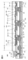
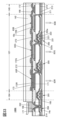
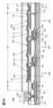
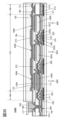
- FIG. 1A to 1C are diagrams illustrating a configuration of a light-emitting device according to an embodiment.
- FIG. 2 is a diagram illustrating a configuration of a light-emitting device according to an embodiment.
- 3A to 3D are diagrams illustrating a configuration of a display device according to an embodiment.
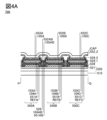
- 4A and 4B are diagrams illustrating a configuration of a display device according to an embodiment.
- 5A to 5C are diagrams illustrating a configuration of a display device according to an embodiment.
- 6A and 6B are diagrams illustrating a configuration of a display device according to an embodiment.
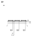
- FIG. 7 is a diagram illustrating a configuration of a display device according to an embodiment.
- FIG. 8 is a diagram illustrating a configuration of a display device according to an embodiment.
- FIG. 9 is a diagram illustrating a configuration of a display device according to an embodiment.
- FIG. 10 is a diagram illustrating a configuration of a display device according to an embodiment.
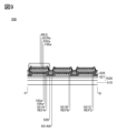
- FIG. 11 is a diagram illustrating a configuration of a display device according to an embodiment.
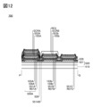
- FIG. 12 is a diagram illustrating a configuration of a display device according to an embodiment.
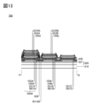
- FIG. 13 is a diagram illustrating a configuration of a display device according to an embodiment.
- FIG. 14 is a diagram illustrating a configuration of a display device according to an embodiment.
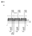
- FIG. 15 is a diagram illustrating a configuration of a display device according to an embodiment.
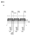
- FIG. 16 is a diagram illustrating a configuration of a display device according to an embodiment.
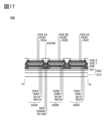
- FIG. 17 is a diagram illustrating a configuration of a display device according to an embodiment.
- FIG. 18 is a diagram illustrating a configuration of a display device according to an embodiment.
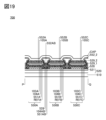
- FIG. 19 is a diagram illustrating a configuration of a display device according to an embodiment.
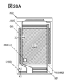
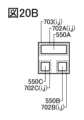
- 20A to 20C are diagrams illustrating a configuration of a display device according to an embodiment.
- FIG. 21 is a diagram illustrating a configuration of a display device according to an embodiment.
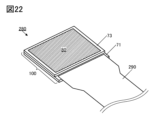
- FIG. 22 is a diagram illustrating a configuration of a display module according to an embodiment.
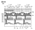
- 23A and 23B are diagrams illustrating a configuration of a display device according to an embodiment.
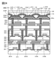
- FIG. 24 is a diagram illustrating a configuration of a display device according to an embodiment.
- FIG. 25 is a diagram illustrating a configuration of a display device according to an embodiment.
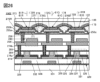
- FIG. 26 is a diagram illustrating a configuration of a display device according to an embodiment.
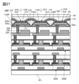
- FIG. 27 is a diagram illustrating a configuration of a display device according to an embodiment.
- FIG. 28 is a diagram illustrating a configuration of a display device according to an embodiment.
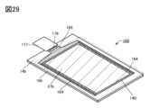
- FIG. 29 is a diagram illustrating a configuration of a display module according to an embodiment.
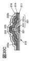
- 30A to 30C are diagrams illustrating a configuration of a display device according to an embodiment.
- FIG. 31 is a diagram illustrating a configuration of a display device according to an embodiment.
- FIG. 32 is a diagram illustrating a configuration of a display device according to an embodiment.
- FIG. 33 is a diagram illustrating a configuration of a display device according to an embodiment.
- FIG. 34 is a diagram illustrating a configuration of a display device according to an embodiment.
- FIG. 35 is a diagram illustrating a configuration of a display device according to an embodiment.
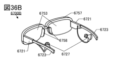
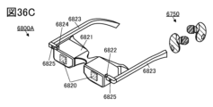
- 36A to 36D are diagrams illustrating an example of an electronic device according to an embodiment.
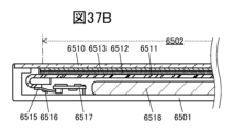
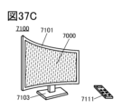
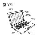
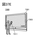
- 37A to 37F are diagrams illustrating an example of an electronic device according to an embodiment.
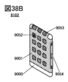
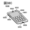
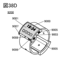
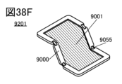
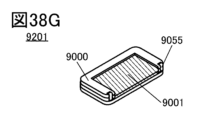
- 38A to 38G are diagrams illustrating an example of an electronic device according to an embodiment.
- a light-emitting device includes a first electrode, a second electrode, a first unit, and a first layer.
- the second electrode overlaps the first electrode, and the second electrode includes metal atoms, and the second electrode includes carbon atoms at a concentration of 5 ⁇ 10 19 atoms/cm 3 or more and 5 ⁇ 10 21 atoms/cm 3 or less.
- the first unit is sandwiched between the first electrode and the second electrode, and the first unit includes a first light-emitting material.
- the first layer is sandwiched between the second electrode and the first unit, and the first layer includes a first organic compound and a second organic compound, the first organic compound has an acid dissociation constant pKa of 8 or more, and the second organic compound has a polarization term ⁇ p of 4.0 MPa 0.5 or less in the solubility parameter ⁇ .
- the second electrode can be formed by using atomic layer deposition. Also, damage to the first layer or the first unit during the manufacturing process can be suppressed. Also, carriers can be easily injected from the second electrode into the first unit. Also, the first layer can be formed without using highly active substances such as alkali metals or alkaline earth metals. Also, resistance to impurities such as air or water can be increased. Also, a decrease in luminous efficiency caused by impurities such as air or water can be suppressed. As a result, a novel light-emitting device with excellent convenience, usefulness, and reliability can be provided.
- Figure 1A is a cross-sectional view illustrating the configuration of a light-emitting device according to one embodiment of the present invention
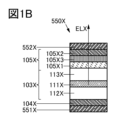
- Figure 1B is a cross-sectional view illustrating a configuration different from that of Figure 1A.
- the configuration of the light-emitting device 550X described in this embodiment can be used for various light sources.
- the light-emitting device 550X can be used for a display device or lighting according to one embodiment of the present invention.
- the description of the configuration of the light-emitting device 550X can be applied to the light-emitting device 550A described in embodiment 5 or embodiment 6.
- the reference character "X" used in the configuration of the light-emitting device 550X can be read as "A” and can be used in the description of the light-emitting device 550A.
- the reference character "X" can be read as "B” or "C” and the configuration of the light-emitting device 550X can be applied to the light-emitting device 550B or the light-emitting device 550C.
- a light-emitting device 550X described in this embodiment includes an electrode 551X, an electrode 552X, a unit 103X, and a layer 105X (see FIG. 1A).
- the light-emitting device 550X has a layer 104X, and the layer 104X is sandwiched between the unit 103X and the electrode 551X.
- the layer 104X is in contact with the electrode 551X. Details of the configuration that can be used for the electrode 551X and the layer 104X will be described in embodiment 3.
- Electrode 552X overlaps with the electrode 551X, and the electrode 552X includes metal atoms.
- a conductive material can be used for the electrode 552X.
- a film containing a metal, an alloy, or a conductive compound can be used for the electrode 552X in a single layer or a multilayer structure.
- a film that efficiently reflects light can be used for the electrode 552X.
- an alloy containing silver and copper, an alloy containing silver and palladium, or a metal film such as aluminum can be used for the electrode 552X.
- a metal film that transmits part of the light and reflects the other part of the light can be used for the electrode 552X.
- a microresonator structure microcavity
- light of a specific wavelength can be extracted more efficiently than other light.
- light with a narrow full width at half maximum of the spectrum can be extracted.
- light of a vivid color can be extracted.
- a film that is transparent to visible light can be used for the electrode 552X.
- a metal film, an alloy film, or a conductive oxide film that is thin enough to transmit light can be used for the electrode 552X in a single layer or a multilayer structure.
- a conductive oxide containing indium can be used for the electrode 552X.
- indium oxide, indium oxide-tin oxide (abbreviation: ITO), indium oxide-tin oxide containing silicon or silicon oxide (abbreviation: ITSO), indium oxide-zinc oxide (abbreviation: InZO), indium oxide containing tungsten oxide and zinc oxide (abbreviation: IWZO), etc. can be used.
- a conductive oxide containing zinc can be used for the electrode 552X.
- zinc oxide, zinc oxide doped with gallium (abbreviation: GZO), zinc oxide doped with aluminum (abbreviation: AZO), or the like can be used.
- gold Au
- platinum Pt
- nickel Ni
- tungsten W
- Cr chromium
- Mo molybdenum
- iron Fe
- Co cobalt
- Cu copper
- palladium Pd
- a nitride of a metal material e.g., titanium nitride
- graphene can be used.
- the electrode 552X when used as the cathode of the light-emitting device 550X, a material having a smaller work function than the electrode 551X can be preferably used for the electrode 552X. Specifically, a material having a work function of 3.8 eV or less is preferable. Furthermore, the material to be used for the electrode 552X can be selected from a wide range of materials regardless of the work function.
- elements belonging to Group 1 of the periodic table, elements belonging to Group 2 of the periodic table, rare earth metals, and alloys containing these can be used for electrode 552X.
- lithium (Li), cesium (Cs), magnesium (Mg), calcium (Ca), strontium (Sr), europium (Eu), ytterbium (Yb), and alloys containing these, such as an alloy of magnesium and silver or an alloy of aluminum and lithium, can be used for the electrode 552X.
- a conductive material containing carbon atoms at a concentration of 5 ⁇ 10 19 atoms/cm 3 or more and 5 ⁇ 10 21 atoms/cm 3 or less can be used for the electrode 552X.
- a conductive material formed by atomic layer deposition (ALD) can be used for the electrode 552X.
- ALD atomic layer deposition
- indium(III) acetylacetonate, trimethylindium, cyclopentadienylindium(I), or the like can be used as a precursor of indium.
- dimethylzinc or diethylzinc can be used as a precursor of zinc.
- tetramethyltin, tetraethyltin, tetrachlorotin, tetrakis(dimethylamino)tin, or bis(dimethylamino-2-methyl-2-propoxy)tin can be used as a precursor of tin.
- trimethylaluminum or aluminum chloride can be used as a precursor of aluminum.
- trimethylgallium or triethylgallium can be used as a precursor of gallium.
- a plurality of the above precursors can be used in combination.
- water can be used as an oxidizing agent. This can suppress the reaction of the oxidizing agent with the base on which the electrode 552X is formed.
- the electrode 552X to be formed, for example, by using atomic layer deposition. Also, damage to the layer 105X or the unit 103X during the manufacturing process can be suppressed. Also, the addition of impurities, such as carbon atoms, may increase the conductivity of the electrode 552X. Note that if the amount of impurities added is too small, the effect of the addition is reduced, and if the amount of impurities added is too large, not only the effect of the addition but also the film quality is impaired. As a result, a novel light-emitting device with excellent convenience, usefulness, and reliability can be provided.
- Example of the configuration of unit 103X The unit 103X is sandwiched between an electrode 551X and an electrode 552X, and contains a light-emitting material EMX. Note that the details of a structure that can be used for the unit 103X will be described in Embodiment 2.
- the layer 105X is sandwiched between the electrode 552X and the unit 103X, and includes an organic compound OCX and an organic compound ETMX.
- the layer 105X is in contact with the electrode 552X.
- Organic compound OCX For example, a material having an acid dissociation constant pKa of 8 or more can be used for the organic compound OCX. Preferably, a material having an acid dissociation constant pKa of 12 or more can be used for the organic compound OCX.
- a material with a large acid dissociation constant pKa has a large dipole moment.
- a material with a large dipole moment interacts with holes.
- the organic compound OCX interacts with holes, and the hole transport property of the layer 105X can be significantly reduced.
- materials with a large acid dissociation constant pKa are highly nucleophilic. Highly nucleophilic materials may react with molecules that have received holes and become cation radicals to generate new molecules or intermediate states. For example, when a material having an acid dissociation constant pKa of 8 or more is used for the organic compound OCX, the organic compound OCX generates new molecules or intermediate states, and the hole transport properties of the layer 105X can be significantly reduced.
- Some of the holes that pass from electrode 551X through unit 103X to reach layer 105X are retained at the interface between unit 103X and layer 105X or at layer 105X. This attracts electrons from electrode 552X, and an electric double layer is formed on the electrode 552X side of layer 105X. As a result, the vacuum level between layer 105X and electrode 552X is distorted, and electrons are supplied from electrode 552X to layer 105X, and electrons are supplied from layer 105X to unit 103X.
- materials with a large acid dissociation constant pKa are highly soluble in water.
- a material having an acid dissociation constant pKa of 8 or more is used for the organic compound OCX, the water resistance of the layer 105X decreases, and defects such as peeling of the layer 105X from other layers occur during the manufacturing process. This may cause defects in the light-emitting device.
- the organic compound ETMX is used together with the organic compound OCX, the water resistance of the layer 105X can be improved. Details of the organic compound ETMX will be described later.
- organic compounds having a large acid dissociation constant pKa organic compounds having a pyrrolidine skeleton, a piperidine skeleton, or a pyrimidine skeleton are preferred. Also, organic compounds having a guanidine skeleton are preferred. Also, organic compounds having a basic skeleton represented by the following structural formulas (120) to (123) can be used.
- the organic compound having an acid dissociation constant pKa of 8 or more is preferably an organic compound having a bicyclo ring structure having two or more nitrogen atoms in the ring, a heteroaromatic ring having 2 to 30 carbon atoms in the ring, or an aromatic hydrocarbon ring having 6 to 30 carbon atoms in the ring, more specifically, an organic compound having a 1,3,4,6,7,8-hexahydro-2H-pyrimido[1,2-a]pyrimidine group, and a heteroaromatic ring having 2 to 30 carbon atoms in the ring, or an aromatic hydrocarbon ring having 6 to 30 carbon atoms in the ring.
- an organic compound having a bicyclo ring structure having two or more nitrogen atoms in the ring, and a heteroaromatic ring having 2 to 30 carbon atoms in the ring is more specifically, an organic compound having a 1,3,4,6,7,8-hexahydro-2H-pyrimido[1,2-a]pyrimidine group, and a heteroaromatic ring having 2 to 30 carbon atoms in the ring, is more preferably an organic compound having a 1,3,4,6,7,8-hexahydro-2H-pyrimido[1,2-a]pyrimidine group, and a heteroaromatic ring having 2 to 30 carbon atoms in the ring.
- the organic compound represented by the following general formula (G1) can be said to be an organic compound having a guanidine skeleton.
- X is a group represented by the following general formula (G1-1)
- Y is a group represented by the following general formula (G1-2).
- R1 and R2 each independently represent hydrogen or deuterium
- h represents an integer of 1 to 6
- Ar represents a substituted or unsubstituted heteroaromatic ring having 2 to 30 carbon atoms constituting the ring, or an aromatic hydrocarbon ring having 6 to 30 carbon atoms constituting the ring.
- Ar is preferably a substituted or unsubstituted heteroaromatic ring having 2 to 30 carbon atoms constituting the ring.
- R3 to R6 each independently represent hydrogen or deuterium, m represents an integer of 0 to 4, n represents an integer of 1 to 5, and m+1 ⁇ n (m+1 is n or greater). When m or n is 2 or greater, the multiple R3 to R6 may be the same or different.
- the organic compound represented by the above general formula (G1) is preferably any one of the following general formulas (G2-1) to (G2-6).
- R 11 to R 26 each independently represent hydrogen or deuterium
- h represents an integer of 1 to 6
- Ar is a substituted or unsubstituted heteroaromatic ring having 2 to 30 carbon atoms constituting a ring, or a substituted or unsubstituted aromatic hydrocarbon ring having 6 to 30 carbon atoms constituting a ring.
- Ar is preferably a substituted or unsubstituted heteroaromatic ring having 2 to 30 carbon atoms constituting a ring.
- examples of the substituted or unsubstituted heteroaromatic ring having 2 to 30 carbon atoms constituting the ring represented by Ar or the aromatic hydrocarbon ring having 6 to 30 carbon atoms constituting the ring include specifically a pyridine ring, a bipyridine ring, a pyrimidine ring, a bipyrimidine ring, a pyrazine ring, a bipyrazine ring, a triazine ring, a quinoline ring, an isoquinoline ring, a benzoquinoline ring, a phenanthroline ring, a quinoxaline ring, a benzoquinoxaline ring, a dibenzoquinoxaline ring, an azofluorene ring, a diazofluorene ring, a carbazole ring, a benzocarbazole ring, a di ...
- the ring examples include a zofuran ring, a benzonaphthofuran ring, a dinaphthofuran ring, a dibenzothiophene ring, a benzonaphthothiophene ring, a dinaphthothiophene ring, a benzofuropyridine ring, a benzofuropyrimidine ring, a benzothiopyrimidine ring, a naphthofuropyridine ring, a naphthofuropyrimidine ring, a naphthothiopyridine ring, a naphthothiopyrimidine ring, an acridine ring, a xanthene ring, a phenothiazine ring, a phenoxazine ring, a phenazine ring, a triazole ring, an oxazole ring, an oxadiazole
- examples of the aromatic hydrocarbon ring having 6 to 30 carbon atoms constituting the substituted or unsubstituted ring represented by Ar include a benzene ring, a naphthalene ring, a fluorene ring, a dimethylfluorene ring, a diphenylfluorene ring, a spirofluorene ring, an anthracene ring, a phenanthrene ring, a triphenylene ring, a pyrene ring, a tetracene ring, a chrysene ring, and a benzo[a]anthracene ring.
- any one of the following structural formulas (Ar-1) to (Ar-27) is preferable.
- the above Ar contains nitrogen as an atom constituting a ring, and that Ar is bonded to the skeleton in parentheses in general formula (G1) via a bond to the nitrogen or a bond to a carbon adjacent to the nitrogen.
- organic compounds represented by the above general formula (G1) and general formulas (G2-1) to (G2-6) include organic compounds represented by the following structural formulas (101) to (117), such as 1,1'-(9,9'-spirobi[9H-fluorene]-2,7-diyl)bis(1,3,4,6,7,8-hexahydro-2H-pyrimido[1,2-a]pyrimidine) (abbreviation: 2,7hpp2SF) (structural formula 108) and 1-(9,9'-spirobi[9H-fluorene]-2-yl)-1,3,4,6,7,8-hexahydro-2H-pyrimido[1,2-a]pyrimidine (abbreviation: 2hppSF) (structural formula 109).
- structural formulas (101) to (117) such as 1,1'-(9,9'-spirobi[9H-fluorene]-2,7-diyl)bis(1,3,4,6,7,8-hexahydro
- organic compounds are less likely to cause metal contamination in the manufacturing line, unlike alkali metals or alkaline earth metals or their compounds, and are easy to vapor-deposit, making them suitable for use in light-emitting devices fabricated using photolithography processes. Of course, they are also suitable for light-emitting devices fabricated using processes that do not use photolithography.
- Organic compounds with an acid dissociation constant pKa of 8 or more include 1-(9,9'-spirobi[9H-fluoren]-2-yl)-1,3,4,6,7,8-hexahydro-2H-pyrimido[1,2-a]pyrimidine (abbreviation: 2hppSF), 2,9-bis(1,3,4,6,7,8-hexahydro-2H-pyrimido[1,2-a]pyrimidin-1-yl)-1,10 -phenanthroline (abbreviation: 2,9hpp2Phen), 4,7-di-1-pyrrolidinyl-1,10-phenanthroline (abbreviation: Pyrrd-Phen), or 8,8'-pyridine-2,6-diyl-bis(5,6,7,8-tetrahydroimidazo[1,2-a]pyrimidine) (abbreviation: 2,6tip2Py), or other organic compounds can be used.
- 2hppSF 2,9-bis(1,3,4,6,
- the substance having a strong basicity of an acid dissociation constant pKa of 8 or more does not have an electron transporting skeleton.
- a nitrogen-containing heterocyclic compound having a guanidine skeleton can be used for the organic compound OCX.
- an organic compound having a 1,3,4,6,7,8-hexahydro-2H-pyrimido[1,2-a]pyrimidine group, an organic compound having a 5,6,7,8-tetrahydroimidazo[1,2-a]pyrimidine group, or a nitrogen-containing heterocyclic compound having a pyrrolidine group can be used for the organic compound OCX.
- 2hppSF, 2,9hpp2Phen, 4,Pyrrd-Phen or 2,6tip2Py can be used for the organic compound OCX.
- the structures of 2hppSF, 2,9hpp2Phen, Pyrrd-Phen and 2,6tip2Py are shown below.
- the acid dissociation constant pKa of 2hppSF is 13.95
- the acid dissociation constant pKa of 2,9hpp2Phen is 13.35
- the acid dissociation constant pKa of Pyrrd-Phen is 11.23
- the acid dissociation constant pKa of 2,6tip2Py is 9.58.
- the organic compound OCX does not have electron donating properties with respect to the organic compound ETMX. If the organic compound OCX has electron donating properties, it will react more easily with atmospheric components such as water or oxygen, resulting in poor stability.
- the layer 105X having the organic compound OCX and the organic compound ETMX according to one embodiment of the present invention has extremely low hole transport properties, and therefore can function as an electron injection layer even if the organic compound OCX does not have electron donating properties. Therefore, it is possible to fabricate an electron injection layer and a light-emitting device that are stable with atmospheric components such as water or oxygen.
- a substance having high electron transport properties can be used for the organic compound ETMX.
- a substance having high electron transport properties refers to a substance having a higher mobility of electrons than holes. Specifically, a substance having an electron mobility of 1 ⁇ 10 ⁇ 7 cm 2 /Vs or more, preferably 1 ⁇ 10 ⁇ 6 cm 2 /Vs or more at a square root of an electric field strength V/cm of 600 is preferable.
- a heteroaromatic compound can be used as an organic compound having high electron transport properties. Note that a heteroaromatic compound is a cyclic compound containing at least two different elements in a ring.
- the ring structure includes a three-membered ring, a four-membered ring, a five-membered ring, a six-membered ring, etc., and in particular, a five-membered ring or a six-membered ring is preferable, and a heteroaromatic compound containing one or more of nitrogen, oxygen, or sulfur in addition to carbon is preferable as an element contained therein.
- a nitrogen-containing heteroaromatic compound nitrogen-containing heteroaromatic compound
- a material with high electron transport properties electron transport material
- an organic compound that does not contain a pyridine ring, does not contain a phenanthroline ring, or has one phenanthroline ring can be used as the organic compound ETMX.
- the acid dissociation constant pKa of a pyridine molecule is 5.25, and the acid dissociation constant pKa of a phenanthroline molecule is 4.8.
- the organic compound's solubility in water increases, and the greater the number of pyridine rings or phenanthroline rings, the higher the solubility of the organic compound in water.
- the solubility in water of an organic compound that has two or more pyridine rings or two or more phenanthroline rings is low.
- using a material that does not contain a pyridine ring, does not contain a phenanthroline ring, or has one phenanthroline ring for organic compound ETMX can improve the water resistance of layer 105X. Furthermore, during the manufacturing process, defects such as layer 105X peeling off from other layers can be suppressed. This can suppress the occurrence of defects that cause defects in the light-emitting device.
- 9-(1-naphthyl)-10-[4-(2-naphthyl)phenyl]anthracene (abbreviation: ⁇ N- ⁇ NPAnth), 2,9-di(naphthalene-2-yl)-4,7-diphenyl-1,10-phenanthroline (abbreviation: NBPhen), 9-[3'-(dibenzothiophene-4-yl)biphenyl-3-yl]naphtho[1',2':4,5]furo[2,3-b]pyrazine (abbreviation: 9mDBtBPNfpr), 8-(biphenyl 8BP-4mDBtPBfpm), 9-[3-(4,6-diphenyl-1,3,5-triazin-2-yl)phenyl]-9'-phenyl-2,3'-bi-9H-carbazole (abbreviation: mPCCzPTzn-02
- NBPhen has one phenanthroline ring.
- a material having an acid dissociation constant pKa smaller than 4 can be used for the organic compound ETMX.
- the solubility of an organic compound having an acid dissociation constant pKa smaller than 4 in water is low compared to the solubility of an organic compound having an acid dissociation constant pKa of 4 or more in water.
- the water resistance of the layer 105X can be improved by using a material having an acid dissociation constant pKa smaller than 4 for the organic compound ETMX.
- the occurrence of defects such as the layer 105X peeling off from other layers during the manufacturing process can be suppressed. This can suppress the occurrence of defects that cause defects in the light-emitting device.
- ⁇ N- ⁇ NPAnth, 9mDBtBPNfpr, 8BP-4mDBtPBfpm, mPCCzPTzn-02, 4,8mDBtP2Bfpm, 6BP-4Cz2PPm, 2mDBTBPDBq-II, BP-BPIcz(II)Tzn, or 11mDBtBPPnfpr can be used as the organic compound ETMX.
- the acid dissociation constant pKa of 4,8mDBtP2Bfpm is 0.60.
- the acid dissociation constant pKa of 11mDBtBPPnfpr is -1.85. If the acid dissociation constant pKa of an organic compound is unknown, the acid dissociation constant pKa of each skeleton of the organic compound can be examined, and the largest acid dissociation constant pKa selected from among them can be regarded as the acid dissociation constant pKa of the organic compound.
- the skeleton with the largest acid dissociation constant pKa is the pyrazine skeleton.
- the acid dissociation constant of the pyrazine molecule is 0.37.
- the acid dissociation constant pKa was calculated using the following calculation method:
- the initial molecular structure of each material used as a calculation model was set to the most stable structure (singlet ground state) obtained from first-principles calculations.
- pKa calculations For pKa calculations, one or more atoms of each molecule were designated as basic sites, and Macro Model was used to search for a structure in which the protonated molecule would be stable in water. A conformational search was performed using the OPLS2005 force field, and the conformer with the lowest energy was used. In addition, Jaguar's pKa calculation module was used, and after structural optimization with B3LYP/6-31G**, a single-point calculation was performed with cc-pVTZ(+), and the pKa value was calculated using an empirical correction for the functional group. For molecules with one or more atoms designated as basic sites, the largest value among the results obtained was used as the pKa value. The obtained pKa values are shown below.
- Example 3 of organic compound ETMX a material having a polarization term ⁇ p of 4.0 MPa 0.5 or less in the solubility parameter ⁇ can be used for the organic compound ETMX.
- the solubility of an organic compound having a polarization term ⁇ p of 4.0 MPa 0.5 or less in the solubility parameter ⁇ is low in comparison with the solubility in water of an organic compound having a polarization term ⁇ p of more than 4.0 MPa 0.5 in the solubility parameter ⁇ .
- the water resistance of the layer 105X can be improved by using a material having a polarization term ⁇ p of 4.0 MPa 0.5 or less for the organic compound ETMX.
- the occurrence of defects such as peeling of the layer 105X from other layers during the manufacturing process can be suppressed. This can suppress the occurrence of defects that cause defects in the light-emitting device.
- ⁇ N- ⁇ NPAnth, NBPhen, 9mDBtBPNfpr, 8BP-4mDBtPBfpm, mPCCzPTzn-02, 4,8mDBtP2Bfpm, 6BP-4Cz2PPm, 2mDBTBPDBq-II, BP-BPIcz(II)Tzn or 11mDBtBPPnfpr can be used for the organic compound ETMX.
- the polarization term ⁇ p of the solubility parameter ⁇ of ⁇ N- ⁇ NPAnth is 4.0 MPa 0.5
- the polarization term ⁇ p of the solubility parameter ⁇ of NBPhen is 4.0 MPa 0.5
- the polarization term ⁇ p of the solubility parameter ⁇ of 9mDBtBPNfpr is 3.8 MPa 0.5
- the polarization term ⁇ p of the solubility parameter ⁇ of 8BP-4mDBtPBfpm is 3.5 MPa 0.5
- the polarization term ⁇ p of the solubility parameter ⁇ of mPCCzPTzn-02 is 3.5 MPa 0.5
- the polarization term ⁇ p of the solubility parameter ⁇ of 6BP-4Cz2PPm is 3.4 MPa 0.5
- the polarization term ⁇ p of the solubility parameter ⁇ of 4,8mDBtP2Bfpm is 3.4 MPa.
- the polarization term ⁇ p of the solubility parameter ⁇ of 2mDBTBPDBq-II is 3.2 MPa 0.5
- the polarization term ⁇ p of the solubility parameter ⁇ of BP-BPIcz(II)Tzn is 3.2 MPa 0.5
- the polarization term ⁇ p of the solubility parameter ⁇ of 11mDBtBPPnfpr is 3.1.
- the polarization term ⁇ p of the solubility parameter ⁇ was calculated using the following calculation method.
- the classical molecular dynamics calculation software used was Desmond manufactured by Schrodinger.
- the force field used was OPLS2005.
- the calculations were performed using Apollo6500 manufactured by HPE.
- a reference cell with approximately 32 molecules was used.
- the most stable structure (singlet ground state) obtained from first-principles calculations and multiple structures with energy close to the most stable structure were mixed in equal ratios, and the molecules were randomly arranged to prevent collisions.
- the structures were randomly moved and rotated by Monte Carlo simulated annealing using OPLS2005 as the force field to move the molecules.
- the molecules were moved toward the center of the reference cell to maximize density, creating the initial arrangement.
- the quantum chemistry calculation software Jaguar was used for the above first-principles calculation, and the most stable structure in the singlet ground state was calculated using density functional theory (DFT). 6-31G** was used as the basis function, and B3LYP-D3 was used as the functional.
- DFT density functional theory
- 6-31G** was used as the basis function
- B3LYP-D3 was used as the functional.
- the structure for the quantum chemistry calculation was sampled by performing conformational analysis using mixed torsional/low-mode sampling using Schrödinger's Maestro GUI. The calculation was performed using HPE's Apollo 6500.
- the above initial configuration was subjected to Brownian motion simulation, followed by NVT ensemble, and then calculations were performed with the ensemble set to NPT, with a sufficient relaxation time (30 ns) for the step time (2 fs) to reproduce the molecular vibration, under conditions of 1 atm and 300 K, to calculate an amorphous solid.
- the solubility parameter ⁇ of the obtained amorphous solid is defined by the following equation.
- ⁇ Hv represents the heat of vaporization, which is the energy of the reference cell minus the total energy of each molecule averaged over the entire molecular dynamics calculation
- Vm represents the molar volume
- R represents the gas constant
- T represents the temperature.
- the solubility parameter ⁇ can be decomposed into a dispersion term ⁇ d and a polarization term ⁇ p.
- the dispersion term ⁇ d is a term contributed by van der Waals interactions
- the polarization term ⁇ p is a term contributed by electrostatic interactions.
- the solubility of a solute in water is greatly contributed by the electrostatic interactions that occur between the solute and the dipoles of water molecules.
- the solubility in water of materials that can be used for the organic compound ETMX shows a good correlation with the polarization term ⁇ p of the solubility parameter ⁇ obtained by calculation.
- the calculated polarization term ⁇ p of the solubility parameter ⁇ is shown in the table below. Note that the value of the polarization term ⁇ p of the solubility parameter ⁇ of water is taken from the value described in JP 2017-173056 A.
- the layer 105X has a small signal or no signal observed by an electron spin resonance (ESR) method.
- ESR electron spin resonance
- the spin density due to a signal observed near a g-value of 2.00 is preferably 1 ⁇ 10 17 spins/cm 3 or less, and more preferably less than 1 ⁇ 10 16 spins/cm 3 .
- the spin density of the material used in the layer 105X can be measured by using an electron spin resonance method using a film formed on a quartz substrate as a sample. For example, it can be measured at room temperature using an electron spin resonance measuring device E500 (manufactured by Bruker) under the conditions of resonance frequency (9.56 GHz), output (1 mW), modulation magnetic field (50 mT), modulation width (0.5 mT), time constant (0.04 s), and sweep time (1 min).
- E500 electron spin resonance measuring device E500 (manufactured by Bruker) under the conditions of resonance frequency (9.56 GHz), output (1 mW), modulation magnetic field (50 mT), modulation width (0.5 mT), time constant (0.04 s), and sweep time (1 min).
- the method for preparing the measurement sample is not particularly limited, but it is preferable to use the same method as the film formation method used in the method for preparing the light-emitting device.
- a film with a thickness of 50 nm can be used as the measurement sample, but it is preferable to use a thicker film for the measurement sample because the signal obtained will be stronger.
- a material having an electron injecting property can be used for the layer 105X.
- the layer 105X can be referred to as an electron injecting layer.
- a substance having electron donating properties can be used for the layer 105X.
- a composite material of a substance having electron donating properties and a material having electron transport properties can be used for the layer 105X.
- an electride can be used for the layer 105X. This can facilitate injection of electrons from the electrode 552X, for example.
- a material for the electrode 552X can be selected from a wide range of materials regardless of the work function. Specifically, aluminum (Al), silver (Ag), indium oxide-tin oxide (abbreviation: ITO), indium oxide-tin oxide containing silicon or silicon oxide, or the like can be used for the electrode 552X.
- the driving voltage of the light-emitting device 550X can be reduced.
- Electrode-donating substance For example, an alkali metal, an alkaline earth metal, a rare earth metal, or a compound thereof (such as an oxide, a halide, or a carbonate) can be used as the electron donating substance.
- an organic compound such as tetrathianaphthacene (abbreviation: TTN), nickelocene, or decamethylnickelocene can be used as the electron donating substance.
- alkali metal compounds including oxides, halides, and carbonates
- lithium oxide lithium fluoride (LiF), cesium fluoride (CsF), lithium carbonate, cesium carbonate, and 8-hydroxyquinolinato-lithium (abbreviation: Liq).
- alkaline earth metal compound including oxides, halides, and carbonates
- calcium fluoride (CaF 2 ) and the like can be used as the alkaline earth metal compound.
- a composite material of a plurality of substances can be used as a material having an electron injecting property.
- a composite material can be used of a substance having an electron donating property and a material having an electron transporting property.
- Electrode-transporting material For example, a material having an electron mobility of 1 ⁇ 10 ⁇ 7 cm 2 /Vs or more and 5 ⁇ 10 ⁇ 5 cm 2 /Vs or less under the condition that the square root of the electric field strength V/cm is 600 can be suitably used as a material having electron transport properties. This makes it possible to control the amount of electrons injected into the light-emitting layer, or to prevent the light-emitting layer from becoming an electron-excessive state.
- a metal complex or an organic compound having a ⁇ -electron-deficient heteroaromatic ring skeleton can be used as a material with electron transport properties.
- metal complexes examples include bis(10-hydroxybenzo[h]quinolinato)beryllium(II) (abbreviation: BeBq2 ), bis(2-methyl-8-quinolinolato)(4-phenylphenolato)aluminum(III) (abbreviation: BAlq), bis(8-quinolinolato)zinc(II) (abbreviation: Znq), bis[2-(2-benzoxazolyl)phenolato]zinc(II) (abbreviation: ZnPBO), bis[2-(2-benzothiazolyl)phenolato]zinc(II) (abbreviation: ZnBTZ), and the like.
- heterocyclic compounds having a polyazole skeleton for example, heterocyclic compounds having a diazine skeleton, heterocyclic compounds having a pyridine skeleton, heterocyclic compounds having a triazine skeleton, etc. can be used.
- heterocyclic compounds having a diazine skeleton or heterocyclic compounds having a pyridine skeleton are preferable because of their good reliability.
- heterocyclic compounds having a diazine (pyrimidine or pyrazine) skeleton have high electron transport properties and can reduce the driving voltage.
- heterocyclic compounds having a polyazole skeleton examples include 2-(4-biphenylyl)-5-(4-tert-butylphenyl)-1,3,4-oxadiazole (abbreviation: PBD), 3-(4-biphenylyl)-4-phenyl-5-(4-tert-butylphenyl)-1,2,4-triazole (abbreviation: TAZ), 1,3-bis[5-(p-tert-butylphenyl)-1,3,4-oxadiazol-2-yl]benzene (abbreviation: O XD-7), 9-[4-(5-phenyl-1,3,4-oxadiazol-2-yl)phenyl]-9H-carbazole (abbreviation: CO11), 2,2',2''-(1,3,5-benzenetriyl)tris(1-phenyl-1H-benzimidazole) (abbreviation: TPBI), 2-[3-(
- heterocyclic compounds having a diazine skeleton examples include 2-[3-(dibenzothiophen-4-yl)phenyl]dibenzo[f,h]quinoxaline (abbreviation: 2mDBTPDBq-II), 2-[3-(3'-dibenzothiophen-4-yl)biphenyl]dibenzo[f,h]quinoxaline (abbreviation: 2mDBTBPDBq-II), 2-[3'-(9H-carbazol-9-yl)biphenyl-3-yl]dibenzo[f,h]quinoxaline (abbreviation: 2mDBTBPDBq-II), Noxaline (abbreviation: 2mCzBPDBq), 4,6-bis[3-(phenanthren-9-yl)phenyl]pyrimidine (abbreviation: 4,6mPnP2Pm), 4,6-bis[3-(4-dibenzothienyl
- heterocyclic compounds having a pyridine skeleton include 3,5-bis[3-(9H-carbazol-9-yl)phenyl]pyridine (abbreviation: 35DCzPPy), 1,3,5-tri[3-(3-pyridyl)phenyl]benzene (abbreviation: TmPyPB), and the like.
- heterocyclic compounds having a triazine skeleton examples include 2-[3'-(9,9-dimethyl-9H-fluoren-2-yl)biphenyl-3-yl]-4,6-diphenyl-1,3,5-triazine (abbreviation: mFBPTzn), 2-(biphenyl-4-yl)-4-phenyl-6-(9,9'-spirobi[9H-fluoren]-2-yl)-1,3,5-triazine (abbreviation: BP-SFTzn).
- mFBPTzn 2-(biphenyl-4-yl)-4-phenyl-6-(9,9'-spirobi[9H-fluoren]-2-yl)-1,3,5-triazine
- a microcrystalline alkali metal fluoride and a material having an electron transporting property can be used for the composite material.
- a microcrystalline alkaline earth metal fluoride and a material having an electron transporting property can be used for the composite material.
- a composite material containing 50 wt % or more of an alkali metal fluoride or an alkaline earth metal fluoride can be preferably used.
- a composite material containing an organic compound having a bipyridine skeleton can be preferably used. This can reduce the refractive index of the layer 105X.
- the external quantum efficiency of the light-emitting device 550X can be improved.
- a composite material including a first organic compound having an unshared electron pair and a first metal can be used for the layer 105X.
- the total number of electrons of the first organic compound and the first metal is an odd number.
- the molar ratio of the first metal to 1 mole of the first organic compound is preferably 0.1 to 10, more preferably 0.2 to 2, and even more preferably 0.2 to 0.8.
- the first organic compound having an unshared electron pair can interact with the first metal to form a Singly Occupied Molecular Orbital (SOMO).
- SOMO Singly Occupied Molecular Orbital
- a composite material having a spin density measured by electron spin resonance (ESR) of preferably 1 ⁇ 10 16 spins/cm 3 or more, more preferably 5 ⁇ 10 16 spins/cm 3 or more, and even more preferably 1 ⁇ 10 17 spins/cm 3 or more can be used for the layer 105X.
- ESR electron spin resonance
- a material having electron transport properties can be used in an organic compound having an unshared electron pair.
- a compound having an electron-deficient heteroaromatic ring can be used.
- a compound having at least one of a pyridine ring, a diazine ring (pyrimidine ring, pyrazine ring, pyridazine ring), and a triazine ring can be used. This can reduce the driving voltage of the light-emitting device 550X.
- the lowest unoccupied molecular orbital (LUMO) level of an organic compound having an unshared electron pair is preferably -3.6 eV or more and -2.3 eV or less.
- the HOMO level and LUMO level of an organic compound can be estimated by CV (cyclic voltammetry), photoelectron spectroscopy, optical absorption spectroscopy, inverse photoelectron spectroscopy, etc.
- BPhen 4,7-diphenyl-1,10-phenanthroline
- NBPhen 2,9-di(naphthalene-2-yl)-4,7-diphenyl-1,10-phenanthroline
- HATNA diquinoxalino[2,3-a:2',3'-c]phenazine
- TmPPPyTz 2,4,6-tris(3'-(pyridin-3-yl)biphenyl-3-yl)-1,3,5-triazine
- TmPPPyTz 2,2'-(1,3-phenylene)bis(9-phenyl-1,10-phenanthroline)
- mPPhen2P 2,2'-(1,3-phenylene)bis(9-phenyl-1,10-phenanthroline
- mPPhen2P 2,2'-(1,3-phenylene)bis(9-phenyl-1,10-phenanthroline
- mPPhen2P 2,2'-(1,3-
- copper phthalocyanine can be used as an organic compound with an unshared electron pair. Note that the number of electrons in copper phthalocyanine is an odd number.
- manganese (Mn), a metal in Group 7, cobalt (Co), a metal in Group 9, copper (Cu), silver (Ag), and gold (Au), which are metals in Group 11, and aluminum (Al) and indium (In), which are metals in Group 13, are odd-numbered groups in the periodic table.
- the elements in Group 11 have a lower melting point than the elements in Groups 7 and 9, and are suitable for vacuum deposition.
- Ag is preferable because of its low melting point.
- the moisture resistance of the light-emitting device 550X can be improved.
- a composite material of the first metal and the first organic compound that are in an even group in the periodic table can be used for layer 105X.
- iron (Fe) which is a metal in Group 8 is in an even group in the periodic table.
- Electrode For example, a substance in which electrons are added at a high concentration to a mixed oxide of calcium and aluminum can be used as a material having electron injection properties.
- a structure in which the layer 105X1 and the layer 105X2 are stacked can be used for the layer 105X (see FIG. 1B).
- the layer 105X1 is sandwiched between the layer 105X2 and the unit 103X.
- the layer 105X2 is in contact with the electrode 552X.
- ⁇ Configuration example of layer 105X1>> For example, the structures described in Structural Example 1 to Structural Example 3 of the layer 105X can be used for the layer 105X1.
- the layer 105X2 may be made of a material that is stable to the process of forming the electrode 552X, which can reduce damage to the light-emitting device when the electrode 552X is formed on the layer 105X2.
- the light-emitting device of one embodiment of the present invention can be manufactured using a method that includes a step of exposing the layer 105X2 to the air. Specifically, after the layer 105X2 is formed, the layer 105X can be exposed to the air. In addition, the electrode 552X2 can be formed on the layer 105X2 exposed to the air. In addition, in the light-emitting device of one embodiment of the present invention, changes in characteristics due to exposure to the air are unlikely to occur.
- a material that has a spin density of 1 ⁇ 10 18 spins/cm 3 or more observed in a film state by electron spin resonance may be used for the layer 105X2.
- a film having an electrical resistivity of 1 ⁇ 10 4 ⁇ cm or more and 1 ⁇ 10 7 ⁇ cm or less may be used for the layer 105X2.
- the layer 105X2 has an electrical resistivity of 5 ⁇ 10 4 ⁇ cm or more and 1 ⁇ 10 7 ⁇ cm or less, and more preferably has an electrical resistivity of 1 ⁇ 10 5 ⁇ cm or more and 1 ⁇ 10 7 ⁇ cm or less.
- Organic and inorganic compounds can be used as the substance having electron accepting properties.
- an organic compound AM having an electron-withdrawing group (a halogen group or a cyano group) can be used as the substance having electron-accepting properties.
- the organic compound AM having electron-accepting properties is easy to vapor-deposit and form into a film. This can increase the productivity of the light-emitting device 550X.
- compounds that can be used include 7,7,8,8-tetracyano-2,3,5,6-tetrafluoroquinodimethane (abbreviation: F4-TCNQ), chloranil, 2,3,6,7,10,11-hexacyano-1,4,5,8,9,12-hexaazatriphenylene (abbreviation: HAT-CN), 1,3,4,5,7,8-hexafluorotetracyano-naphthoquinodimethane (abbreviation: F6-TCCNNQ), 2-(7-dicyanomethylene-1,3,4,5,6,8,9,10-octafluoro-7H-pyren-2-ylidene)malononitrile, and the like.
- radialene derivatives [3] that have an electron-withdrawing group are preferred because they have very high electron-accepting properties.
- Specific examples include ⁇ , ⁇ ', ⁇ ''-1,2,3-cyclopropane triylidene tris[4-cyano-2,3,5,6-tetrafluorobenzeneacetonitrile], ⁇ , ⁇ ', ⁇ ''-1,2,3-cyclopropane triylidene tris[2,6-dichloro-3,5-difluoro-4-(trifluoromethyl)benzeneacetonitrile], ⁇ , ⁇ ', ⁇ ''-1,2,3-cyclopropane triylidene tris[2,3,4,5,6-pentafluorobenzeneacetonitrile], and the like.
- transition metal oxides such as molybdenum oxide, vanadium oxide, ruthenium oxide, tungsten oxide, and manganese oxide can be used as electron-accepting substances.
- phthalocyanine compounds such as phthalocyanine (abbreviation: H2Pc), phthalocyanine complex compounds such as copper (II) phthalocyanine (abbreviation: CuPc), and compounds having an aromatic amine skeleton such as 4,4'-bis[N-(4-diphenylaminophenyl)-N-phenylamino]biphenyl (abbreviation: DPAB) and N,N'-bis[4-bis(3-methylphenyl)aminophenyl]-N,N'-diphenyl-4,4'-diaminobiphenyl (abbreviation: DNTPD) can be used.
- H2Pc phthalocyanine
- CuPc phthalocyanine complex compounds
- DNTPD diphenyl
- polymers such as poly(3,4-ethylenedioxythiophene)/polystyrenesulfonic acid (abbreviation: PEDOT/PSS) can be used.
- a composite material including a substance having an electron accepting property and a material having a hole transporting property can be used for the layer 105X2.
- a material for the electrode 552X can be selected from a wide range of materials regardless of the work function.
- an organic compound HTM having at least one of a ⁇ -electron-rich heteroaromatic ring and an aromatic amine can be used as a material having a hole transporting property.
- a compound having an aromatic amine skeleton, a carbazole derivative, an aromatic hydrocarbon, an aromatic hydrocarbon having a vinyl group, a polymer compound (oligomer, dendrimer, polymer, etc.), etc. can be used as the organic compound HTM.
- a material having a hole mobility of 1 ⁇ 10 ⁇ 6 cm 2 /Vs or more can be suitably used as the organic compound HTM.
- a material having a hole transporting property that can be used for the layer 112X described later can be used as the organic compound HTM.
- Examples of compounds having an aromatic amine skeleton that can be used include N,N'-di(p-tolyl)-N,N'-diphenyl-p-phenylenediamine (abbreviation: DTDPPA), 4,4'-bis[N-(4-diphenylaminophenyl)-N-phenylamino]biphenyl (abbreviation: DPAB), N,N'-bis[4-bis(3-methylphenyl)aminophenyl]-N,N'-diphenyl-4,4'-diaminobiphenyl (abbreviation: DNTPD), 1,3,5-tris[N-(4-diphenylaminophenyl)-N-phenylamino]benzene (abbreviation: DPA3B), etc.
- DTDPPA N,N'-di(p-tolyl)-N,N'-diphenyl-p-phenylenediamine
- DPAB
- carbazole derivatives include 3-[N-(9-phenylcarbazol-3-yl)-N-phenylamino]-9-phenylcarbazole (abbreviation: PCzPCA1), 3,6-bis[N-(9-phenylcarbazol-3-yl)-N-phenylamino]-9-phenylcarbazole (abbreviation: PCzPCA2), 3-[N-(1-naphthyl)-N-(9-phenylcarbazol-3-yl)amino]-9-phenylcarbazole, azole (abbreviation: PCzPCN1), 4,4'-di(N-carbazolyl)biphenyl (abbreviation: CBP), 1,3,5-tris[4-(N-carbazolyl)phenyl]benzene (abbreviation: TCPB), 9-[4-(10-phenyl-9-anthracenyl)phenyl
- aromatic hydrocarbons examples include 2-tert-butyl-9,10-di(2-naphthyl)anthracene (abbreviation: t-BuDNA), 2-tert-butyl-9,10-di(1-naphthyl)anthracene, 9,10-bis(3,5-diphenylphenyl)anthracene (abbreviation: DPPA), 2-tert-butyl-9,10-bis(4-phenylphenyl)anthracene (abbreviation: t-BuDBA), 9,10-di(2-naphthyl)anthracene (abbreviation: DNA), 9,10-diphenylanthracene (abbreviation: DPAnth), 2-tert-butylanthracene (abbreviation: t-BuAnth), 9,10-bis(4-methyl-1-naphthyl)anthracene (abbreviation: DMNA
- aromatic hydrocarbons having a vinyl group examples include 4,4'-bis(2,2-diphenylvinyl)biphenyl (abbreviation: DPVBi), 9,10-bis[4-(2,2-diphenylvinyl)phenyl]anthracene (abbreviation: DPVPA), etc.
- polymer compounds examples include poly(N-vinylcarbazole) (abbreviation: PVK), poly(4-vinyltriphenylamine) (abbreviation: PVTPA), poly[N-(4- ⁇ N'-[4-(4-diphenylamino)phenyl]phenyl-N'-phenylamino ⁇ phenyl) methacrylamide] (abbreviation: PTPDMA), poly[N,N'-bis(4-butylphenyl)-N,N'-bis(phenyl)benzidine] (abbreviation: Poly-TPD), etc.
- PVK poly(N-vinylcarbazole)
- PVTPA poly(4-vinyltriphenylamine)
- PTPDMA poly[N-(4- ⁇ N'-[4-(4-diphenylamino)phenyl]phenyl-N'-phenylamino ⁇ phenyl) methacrylamide]
- PTPDMA poly[
- a substance having any one of a carbazole skeleton, a dibenzofuran skeleton, a dibenzothiophene skeleton, and an anthracene skeleton can be suitably used as a material having hole transport properties of the composite material.
- an aromatic amine having a substituent containing a dibenzofuran ring or a dibenzothiophene ring, an aromatic monoamine having a naphthalene ring, or a substance having an aromatic monoamine in which a 9-fluorenyl group is bonded to the nitrogen of the amine via an arylene group can be used as a material having hole transport properties of the composite material.
- the use of a substance having an N,N-bis(4-biphenyl)amino group can improve the reliability of the light-emitting device 550X.
- N-(4-biphenyl)-6,N-diphenylbenzo[b]naphtho[1,2-d]furan-8-amine abbreviation: BnfABP
- BnfABP N,N-bis(4-biphenyl)-6-phenylbenzo[b]naphtho[1,2-d]furan-8-amine
- BBABnf 4,4'-bis(6-phenylbenzo[b]naphtho[1,2-d]furan -8-yl)-4"-phenyltriphenylamine
- BnfBB1BP N,N-bis(4-biphenyl)benzo[b]naphtho[1,2-d]furan-6-amine
- BBABnf(6) N,N-bis(4-biphenyl)benzo[b]naphtho[1,2-d]furan-8-amine
- a structure in which the layers 105X21 and 105X22 are stacked can be used for the layer 105X2 (see FIG. 1C).
- the layer 105X21 contains an organic compound AM
- the layer 105X22 contains an organic compound HTM. It is preferable that the layer 105X22 contacts the layer 105X21. It is also preferable that the layer 105X21 is sandwiched between the electrode 552X and the layer 105X22. This facilitates the transfer of carriers between the layer 105X2 and the electrode 552X. It is also possible to suppress an increase in the driving voltage of the light-emitting device.
- a structure in which layers 105X1, 105X2, and 105X3 are stacked can be used for the layer 105X (see FIGS. 1B and 1C).
- the layer 105X1 is sandwiched between the layer 105X3 and the unit 103X, and the layer 105X3 is sandwiched between the layer 105X2 and the layer 105X1.
- the layer 105X2 contacts the electrode 552X.
- a material having a LUMO level in the range of -4.3 eV to -3.0 eV can be used for layer 105X3. This facilitates the transfer of carriers between layers 105X2 and 105X1, and also prevents an increase in the driving voltage of the light-emitting device.
- phthalocyanine-based materials can be used for the layer 105X3.
- metal phthalocyanines having copper, zinc, cobalt, iron, chromium, nickel, or the like such as phthalocyanine (abbreviation: H2Pc), copper (II) phthalocyanine (abbreviation: CuPc), zinc phthalocyanine (abbreviation: ZnPc), cobalt phthalocyanine (abbreviation: CoPc), iron phthalocyanine (abbreviation: FePc), tin phthalocyanine (abbreviation: SnPc), tin oxide phthalocyanine (abbreviation: SnOPc), titanium oxide phthalocyanine (abbreviation: TiOPc), vanadium oxide phthalocyanine (abbreviation: VOPc), and derivatives thereof, or metal complexes having a metal-oxygen bond and an aromatic ligand, diquinoxa Perylene tetracarboxy
- the thickness of layer 105X3 is preferably 1 nm or more and 10 nm or less, and more preferably 2 nm or more and 5 nm or less.
- layer 105X to supply electrons to unit 103X.
- layer 105X can be constructed without using highly active substances such as alkali metals or alkaline earth metals. Furthermore, resistance to impurities such as air or water can be increased. Furthermore, a decrease in luminous efficiency caused by impurities such as air or water can be suppressed. As a result, a novel light-emitting device with excellent convenience, usefulness, and reliability can be provided.
- Figure 1A is a cross-sectional view illustrating the configuration of a light-emitting device according to one embodiment of the present invention.
- a light-emitting device 550X described in this embodiment includes an electrode 551X, an electrode 552X, and a unit 103X.
- the electrode 552X overlaps with the electrode 551X, and the unit 103X is sandwiched between the electrode 552X and the electrode 551X.
- the unit 103X has a single layer structure or a laminated structure.
- the unit 103X includes a layer 111X, a layer 112X, and a layer 113X (see FIG. 1A).
- the unit 103X has a function of emitting light ELX.
- Layer 111X is sandwiched between layers 113X and 112X, layer 113X is sandwiched between electrode 552X and layer 111X, and layer 112X is sandwiched between layer 111X and electrode 551X.
- a layer selected from functional layers such as a light-emitting layer, a hole transport layer, an electron transport layer, and a carrier block layer can be used in unit 103X.
- a layer selected from functional layers such as a hole injection layer, an electron injection layer, an exciton block layer, and a charge generation layer can be used in unit 103X.
- a material having a hole transporting property can be used for the layer 112X.
- the layer 112X can be referred to as a hole transporting layer.
- a material having a larger band gap than that of the light-emitting material contained in the layer 111X is preferably used for the layer 112X. This can suppress energy transfer from excitons generated in the layer 111X to the layer 112X.
- a material having a hole mobility of 1 ⁇ 10 ⁇ 6 cm 2 /Vs or more can be suitably used as the material having a hole transport property.
- an amine compound or an organic compound having a ⁇ -electron-rich heteroaromatic ring skeleton can be used as a material having hole transport properties.
- a compound having an aromatic amine skeleton, a compound having a carbazole skeleton, a compound having a thiophene skeleton, a compound having a furan skeleton, etc. can be used.
- a compound having an aromatic amine skeleton or a compound having a carbazole skeleton is preferable because it has good reliability, has high hole transport properties, and contributes to reducing the driving voltage.
- Examples of compounds having an aromatic amine skeleton include 4,4'-bis[N-(1-naphthyl)-N-phenylamino]biphenyl (abbreviation: NPB), N,N'-diphenyl-N,N'-bis(3-methylphenyl)-4,4'-diaminobiphenyl (abbreviation: TPD), N,N'-bis(9,9'-spirobi[9H-fluorene]-2-yl)-N,N'-diphenyl-4,4'-diaminobiphenyl (abbreviation: BSPB), 4-phenyl-4'-(9-phenylfluorene-9-yl)triphenylamine (abbreviation: BPAFLP), 4-phenyl-3'-(9-phenylfluorene-9-yl)triphenylamine (abbreviation: mBPAFLP), 4-phenyl-4'-(9-phenyl-9H
- Examples of compounds having a carbazole skeleton that can be used include 1,3-bis(N-carbazolyl)benzene (abbreviation: mCP), 4,4'-di(N-carbazolyl)biphenyl (abbreviation: CBP), 3,6-bis(3,5-diphenylphenyl)-9-phenylcarbazole (abbreviation: CzTP), and 3,3'-bis(9-phenyl-9H-carbazole) (abbreviation: PCCP).
- mCP 1,3-bis(N-carbazolyl)benzene
- CBP 4,4'-di(N-carbazolyl)biphenyl
- CzTP 3,6-bis(3,5-diphenylphenyl)-9-phenylcarbazole
- PCCP 3,3'-bis(9-phenyl-9H-carbazole
- Examples of compounds having a thiophene skeleton that can be used include 4,4',4''-(benzene-1,3,5-triyl)tri(dibenzothiophene) (abbreviation: DBT3P-II), 2,8-diphenyl-4-[4-(9-phenyl-9H-fluoren-9-yl)phenyl]dibenzothiophene (abbreviation: DBTFLP-III), 4-[4-(9-phenyl-9H-fluoren-9-yl)phenyl]-6-phenyldibenzothiophene (abbreviation: DBTFLP-IV), etc.
- DBT3P-II 4,4',4''-(benzene-1,3,5-triyl)tri(dibenzothiophene)
- DBTFLP-III 2,8-diphenyl-4-[4-(9-phenyl-9H-fluoren-9-yl)phenyl]
- Examples of compounds having a furan skeleton that can be used include 4,4',4''-(benzene-1,3,5-triyl)tri(dibenzofuran) (abbreviation: DBF3P-II), 4- ⁇ 3-[3-(9-phenyl-9H-fluoren-9-yl)phenyl]phenyl ⁇ dibenzofuran (abbreviation: mmDBFFLBi-II), etc.
- a material having an electron transporting property a material having an anthracene skeleton, a mixed material, or the like can be used for the layer 113X.
- the layer 113X can be referred to as an electron transporting layer.
- a material having a larger band gap than that of the light-emitting material contained in the layer 111X is preferably used for the layer 113X. This can suppress energy transfer from excitons generated in the layer 111X to the layer 113X.
- Electrode-transporting material For example, a material having an electron mobility of 1 ⁇ 10 ⁇ 7 cm 2 /Vs or more and 5 ⁇ 10 ⁇ 5 cm 2 /Vs or less under the condition that the square root of the electric field strength V/cm is 600 can be suitably used as a material having electron transport properties. This makes it possible to suppress the transport properties of electrons in the electron transport layer. Alternatively, it is possible to control the amount of electrons injected into the light-emitting layer. Alternatively, it is possible to prevent the light-emitting layer from becoming in an electron-excess state.
- a metal complex or an organic compound having a ⁇ -electron-deficient heteroaromatic ring skeleton can be used as a material with electron transport properties.
- metal complexes examples include bis(10-hydroxybenzo[h]quinolinato)beryllium(II) (abbreviation: BeBq2 ), bis(2-methyl-8-quinolinolato)(4-phenylphenolato)aluminum(III) (abbreviation: BAlq), bis(8-quinolinolato)zinc(II) (abbreviation: Znq), bis[2-(2-benzoxazolyl)phenolato]zinc(II) (abbreviation: ZnPBO), bis[2-(2-benzothiazolyl)phenolato]zinc(II) (abbreviation: ZnBTZ), and the like.
- heterocyclic compounds having a polyazole skeleton for example, heterocyclic compounds having a diazine skeleton, heterocyclic compounds having a pyridine skeleton, heterocyclic compounds having a triazine skeleton, etc. can be used.
- heterocyclic compounds having a diazine skeleton or heterocyclic compounds having a pyridine skeleton are preferable because of their good reliability.
- heterocyclic compounds having a diazine (pyrimidine or pyrazine) skeleton have high electron transport properties and can reduce the driving voltage.
- heterocyclic compounds having a polyazole skeleton examples include 2-(4-biphenylyl)-5-(4-tert-butylphenyl)-1,3,4-oxadiazole (abbreviation: PBD), 3-(4-biphenylyl)-4-phenyl-5-(4-tert-butylphenyl)-1,2,4-triazole (abbreviation: TAZ), 1,3-bis[5-(p-tert-butylphenyl)-1,3,4-oxadiazol-2-yl]benzene (abbreviation: O XD-7), 9-[4-(5-phenyl-1,3,4-oxadiazol-2-yl)phenyl]-9H-carbazole (abbreviation: CO11), 2,2',2''-(1,3,5-benzenetriyl)tris(1-phenyl-1H-benzimidazole) (abbreviation: TPBI), 2-[3-(
- heterocyclic compounds having a diazine skeleton examples include 2-[3-(dibenzothiophen-4-yl)phenyl]dibenzo[f,h]quinoxaline (abbreviation: 2mDBTPDBq-II), 2-[3-(3'-dibenzothiophen-4-yl)biphenyl]dibenzo[f,h]quinoxaline (abbreviation: 2mDBTBPDBq-II), 2-[3'-(9H-carbazol-9-yl)biphenyl-3-yl]dibenzo[f,h]quinoxaline (abbreviation: 2mDBTBPDBq-II), Noxaline (abbreviation: 2mCzBPDBq), 4,6-bis[3-(phenanthren-9-yl)phenyl]pyrimidine (abbreviation: 4,6mPnP2Pm), 4,6-bis[3-(4-dibenzothienyl
- heterocyclic compounds having a pyridine skeleton include 3,5-bis[3-(9H-carbazol-9-yl)phenyl]pyridine (abbreviation: 35DCzPPy), 1,3,5-tri[3-(3-pyridyl)phenyl]benzene (abbreviation: TmPyPB), and the like.
- heterocyclic compounds having a triazine skeleton examples include 2-[3'-(9,9-dimethyl-9H-fluoren-2-yl)biphenyl-3-yl]-4,6-diphenyl-1,3,5-triazine (abbreviation: mFBPTzn), 2-(biphenyl-4-yl)-4-phenyl-6-(9,9'-spirobi[9H-fluoren]-2-yl)-1,3,5-triazine (abbreviation: BP-SFTzn).
- mFBPTzn 2-(biphenyl-4-yl)-4-phenyl-6-(9,9'-spirobi[9H-fluoren]-2-yl)-1,3,5-triazine
- An organic compound having an anthracene skeleton can be used for the layer 113X.
- an organic compound containing both an anthracene skeleton and a heterocyclic skeleton can be suitably used.
- an organic compound containing both an anthracene skeleton and a nitrogen-containing five-membered ring skeleton can be used for layer 113X.
- an organic compound containing both an anthracene skeleton and a nitrogen-containing five-membered ring skeleton containing two heteroatoms in the ring can be used for layer 113X.
- a pyrazole ring, an imidazole ring, an oxazole ring, a thiazole ring, or the like can be suitably used for the heterocyclic skeleton.
- an organic compound containing both an anthracene skeleton and a nitrogen-containing six-membered ring skeleton can be used for layer 113X.
- an organic compound containing both an anthracene skeleton and a nitrogen-containing six-membered ring skeleton containing two heteroatoms in the ring can be used for layer 113X.
- a pyrazine ring, a pyrimidine ring, a pyridazine ring, or the like can be suitably used for the heterocyclic skeleton.
- a mixture of a plurality of substances can be used for the layer 113X.
- a mixture of an alkali metal, an alkali metal compound, or an alkali metal complex, and a substance having an electron-transporting property can be used for the layer 113X.
- the HOMO level of the material having an electron-transporting property is more preferably ⁇ 6.0 eV or higher.
- the composite material described in embodiment 3 can be preferably used for the layer 113X in combination with a structure in which the composite material is used for the layer 104X.
- a composite material of a substance having an electron-accepting property and a material having a hole-transporting property can be used for the layer 104X.
- a composite material of a substance having an electron-accepting property and a substance having a relatively deep HOMO level HM1 of -5.7 eV or more and -5.4 eV or less can be used for the layer 104X.
- a structure in which the mixed material is used in layer 113X and the above composite material is used in layer 104X with a structure in which a material having hole transport properties is used in layer 112X.
- a substance having a HOMO level HM2 in the range of -0.2 eV to 0 eV with respect to the above relatively deep HOMO level HM1 can be used in layer 112X. This can improve the reliability of the light-emitting device.
- the above light-emitting device may be referred to as a Recombination-Site Tailoring Injection structure (ReSTI structure).
- the alkali metal, alkali metal compound, or alkali metal complex exists with a concentration difference (including the case where the concentration difference is 0) in the thickness direction of layer 113X.
- a metal complex containing an 8-hydroxyquinolinato structure can be used.
- a methyl-substituted metal complex containing an 8-hydroxyquinolinato structure e.g., a 2-methyl-substituted or 5-methyl-substituted metal complex
- a metal complex containing an 8-hydroxyquinolinato structure e.g., a 2-methyl-substituted or 5-methyl-substituted metal complex
- 8-hydroxyquinolinato-lithium abbreviation: Liq
- 8-hydroxyquinolinato-sodium abbreviation: Naq
- complexes of monovalent metal ions, especially lithium complexes are preferred, with Liq being more preferred.
- Configuration Example 1 of Layer 111X For example, a light-emitting material, or a light-emitting material and a host material can be used for the layer 111X.
- the layer 111X can be called a light-emitting layer. Note that a configuration in which the layer 111X is disposed in a region where holes and electrons recombine is preferable. This allows the energy generated by the recombination of carriers to be efficiently converted into light and emitted.
- layer 111X away from metals used in electrodes, etc. This makes it possible to suppress the quenching phenomenon caused by metals used in electrodes, etc.
- a microresonator structure can be formed by placing layer 111X at an appropriate position between the electrodes, etc.
- a fluorescent material for example, a fluorescent material, a phosphorescent material, or a material that exhibits thermally activated delayed fluorescence (TADF) (also called a TADF material) can be used as the luminescent material.
- TADF thermally activated delayed fluorescence
- fluorescent material A fluorescent substance can be used for the layer 111X.
- the following fluorescent substances can be used for the layer 111X.
- the present invention is not limited thereto, and various known fluorescent substances can be used for the layer 111X.
- condensed aromatic diamine compounds such as pyrene diamine compounds, such as 1,6FLPAPrn, 1,6mMemFLPAPrn, and 1,6BnfAPrn-03, are preferred because they have high hole trapping properties and excellent luminous efficiency or reliability.
- N-[4-(9,10-diphenyl-2-anthryl)phenyl]-N,N',N'-triphenyl-1,4-phenylenediamine abbreviation: 2DPAPPA
- N,N,N',N',N'',N'',N'',N''',N'''-octaphenyldibenzo[g,p]chrysene-2,7,10,15-tetraamine abmarin 30, 9,10-diphenyl-2-[N-phenyl-N-(9-phenyl-carbazol-3-yl)-amino]-anthracene (abbreviation: 2PCAPA), N-[9,10-bis(biphenyl-2-yl)-2-anthryl]-N,9-diphenyl-9H-carbazol-3-amine (abbreviation: 2PCABPhA), N-(9,10-diphenyl-9H-carbazol-3
- DCM1 2-(2- ⁇ 2-[4-(dimethylamino)phenyl]ethenyl ⁇ -6-methyl-4H-pyran-4-ylidene)propanedinitrile
- DCM2 2- ⁇ 2-methyl-6-[2-(2,3,6,7-tetrahydro-1H,5H-benzo[ij]quinolizin-9-yl)ethenyl]-4H-pyran-4-ylidene ⁇ propanedinitrile
- DCM3 N,N,N',N'-tetrakis(2-methyl-6-[2-(2,3,6,7-tetrahydro-1H,5H-benzo[ij]quinolizin-9-yl)ethenyl]-4H-pyran-4-ylidene ⁇ propanedinitrile
- DCM3 p-mPhTD
- a phosphorescent material can be used for the layer 111X.
- the phosphorescent material exemplified below can be used for the layer 111X. Note that the present invention is not limited thereto, and various known phosphorescent materials can be used for the layer 111X.
- organometallic iridium complexes having a 4H-triazole skeleton organometallic iridium complexes having a 1H-triazole skeleton, organometallic iridium complexes having an imidazole skeleton, organometallic iridium complexes having a phenylpyridine derivative having an electron-withdrawing group as a ligand, organometallic iridium complexes having a pyrimidine skeleton, organometallic iridium complexes having a pyrazine skeleton, organometallic iridium complexes having a pyridine skeleton, rare earth metal complexes, platinum complexes, and the like can be used for layer 111X.
- organometallic iridium complexes having a 4H-triazole skeleton include tris ⁇ 2-[5-(2-methylphenyl)-4-(2,6-dimethylphenyl)-4H-1,2,4-triazol- 3 -yl- ⁇ N2]phenyl- ⁇ C ⁇ iridium(III) (abbreviation: [Ir(mpptz-dmp) 3 ]), tris(5-methyl-3,4-diphenyl-4H-1,2,4-triazolato)iridium(III) (abbreviation: [Ir(Mptz) 3 ]), tris[4-(3-biphenyl)-5-isopropyl-3-phenyl-4H-1,2,4-triazolato]iridium(III) (abbreviation: [Ir(iPrptz-3b) 3 ]), and the like.
- organometallic iridium complexes having a 1H-triazole skeleton examples include tris[3-methyl-1-(2-methylphenyl)-5-phenyl-1H-1,2,4-triazolato]iridium(III) (abbreviation: [Ir(Mptz1-mp) 3 ]), tris(1-methyl-5-phenyl-3-propyl-1H-1,2,4-triazolato)iridium(III) (abbreviation: [Ir(Prptz1-Me) 3 ]), and the like.
- organometallic iridium complexes having an imidazole skeleton examples include fac-tris[1-(2,6-diisopropylphenyl)-2-phenyl-1H-imidazole]iridium(III) (abbreviation: [Ir(iPrpim) 3 ]), tris[3-(2,6-dimethylphenyl)-7-methylimidazo[1,2-f]phenanthridinato]iridium(III) (abbreviation: [Ir(dmpimpt-Me) 3 ]), and the like.
- organometallic iridium complexes having a phenylpyridine derivative having an electron-withdrawing group as a ligand include bis[2-(4',6'-difluorophenyl)pyridinato-N,C2 ' ]iridium(III) tetrakis(1-pyrazolyl)borate (abbreviation: FIr6), bis[2-(4',6'-difluorophenyl)pyridinato-N,C2 ' ]iridium(III) picolinate (abbreviation: FIrpic), bis ⁇ 2-[3',5'-bis(trifluoromethyl)phenyl]pyridinato-N, C2' ⁇ iridium(III) picolinate (abbreviation: [Ir( CF3ppy ) 2 (pic)]), and bis[2-(4',6'-difluorophenyl)pyridinato-N,C2 '
- These compounds emit blue phosphorescence and have a peak emission wavelength between 440 nm and 520 nm.
- organometallic iridium complexes having a pyrimidine skeleton examples include tris(4-methyl-6-phenylpyrimidinato)iridium(III) (abbreviation: [Ir(mppm) 3 ]), tris(4-t-butyl-6-phenylpyrimidinato)iridium(III) (abbreviation: [Ir(tBuppm) 3 ]), (acetylacetonato)bis(6-methyl-4-phenylpyrimidinato)iridium(III) (abbreviation: [Ir(mppm) 2 (acac)]), (acetylacetonato)bis(6-tert-butyl-4-phenylpyrimidinato)iridium(III) (abbreviation: [Ir(tBuppm) 2 (acac)]), (acetylacetonato)bis[6-(2-norbornyl)
- organometallic iridium complexes having a pyrazine skeleton examples include (acetylacetonato)bis(3,5-dimethyl-2-phenylpyrazinato)iridium(III) (abbreviation: [Ir(mppr-Me) 2 (acac)]), (acetylacetonato)bis(5-isopropyl-3-methyl-2-phenylpyrazinato)iridium(III) (abbreviation: [Ir(mppr-iPr) 2 (acac)]), and the like.
- organometallic iridium complexes having a pyridine skeleton examples include tris(2-phenylpyridinato-N,C 2′ )iridium(III) (abbreviation: [Ir(ppy) 3 ]), bis(2-phenylpyridinato-N,C 2′ )iridium(III) acetylacetonate (abbreviation: [Ir(ppy) 2 (acac)]), bis(benzo[h]quinolinato)iridium(III) acetylacetonate (abbreviation: [Ir(bzq) 2 (acac)]), tris(benzo[h]quinolinato)iridium(III) (abbreviation: [Ir(bzq) 3 ]), and tris(2-phenylquinolinato-N,C 2′ )iridium(III) (abbreviation: [Ir(pq) 3 ]), bis(2-phenylquinolinato-N,
- rare earth metal complexes examples include tris(acetylacetonato)(monophenanthroline)terbium(III) (abbreviation: [Tb(acac) 3 (Phen)]).
- organometallic iridium complexes with a pyrimidine skeleton are remarkably superior in terms of reliability and luminous efficiency.
- organometallic iridium complexes having a pyrimidine skeleton examples include (diisobutyrylmethanato)bis[4,6-bis(3-methylphenyl)pyrimidinato]iridium(III) (abbreviation: [Ir(5mdppm) 2 (dibm)]), bis[4,6-bis(3-methylphenyl)pyrimidinato](dipivaloylmethanato)iridium(III) (abbreviation: [Ir(5mdppm) 2 (dpm)]), and bis[4,6-di(naphthalen-1-yl)pyrimidinato](dipivaloylmethanato)iridium(III) (abbreviation: [Ir(d1npm) 2 (dpm)]).
- organometallic iridium complexes having a pyrazine skeleton examples include (acetylacetonato)bis(2,3,5-triphenylpyrazinato)iridium(III) (abbreviation: [Ir(tppr) 2 (acac)]), bis(2,3,5-triphenylpyrazinato)(dipivaloylmethanato)iridium(III) (abbreviation: [Ir(tppr) 2 (dpm)]), (acetylacetonato)bis[2,3-bis(4-fluorophenyl)quinoxalinato]iridium(III) (abbreviation: [Ir(Fdpq) 2 (acac)]), and the like.
- organometallic iridium complexes having a pyridine skeleton examples include tris(1-phenylisoquinolinato-N,C2 ' )iridium(III) (abbreviation: [Ir(piq) 3 ]), bis(1-phenylisoquinolinato-N,C2 ' )iridium(III) acetylacetonate (abbreviation: [Ir(piq) 2 (acac)]), and the like.
- rare earth metal complexes examples include tris(1,3-diphenyl-1,3-propanedionato)(monophenanthroline)europium(III) (abbreviation: [Eu(DBM) 3 (Phen)]), tris[1-(2-thenoyl)-3,3,3-trifluoroacetonato](monophenanthroline)europium(III) (abbreviation: [Eu(TTA) 3 (Phen)]), and the like.
- platinum complexes examples include 2,3,7,8,12,13,17,18-octaethyl-21H,23H-porphyrin platinum(II) (abbreviation: PtOEP).
- organometallic iridium complexes having a pyrazine skeleton can emit red light with a chromaticity suitable for use in display devices.
- a TADF material can be used for the layer 111X.
- the S1 level of the host material is preferably higher than the S1 level of the TADF material.
- the T1 level of the host material is preferably higher than the T1 level of the TADF material.
- the TADF materials shown below can be used as the luminescent material. However, this is not limited to these, and various known TADF materials can be used.
- the difference between the S1 and T1 levels of TADF materials is small, and reverse intersystem crossing (upconversion) from the triplet excited state to the singlet excited state can be achieved with a small amount of thermal energy. This allows efficient generation of the singlet excited state from the triplet excited state.
- the triplet excited energy can be converted into light emission.
- exciplexes also called exciplexes
- TADF materials that can convert triplet excitation energy into singlet excitation energy
- the phosphorescence spectrum observed at low temperatures may be used as an index of the T1 level.
- the TADF material when a tangent line is drawn at the short-wavelength tail of the fluorescence spectrum, and the energy of the wavelength of the extrapolated line is taken as the S1 level, and a tangent line is drawn at the short-wavelength tail of the phosphorescence spectrum, and the energy of the wavelength of the extrapolated line is taken as the T1 level, the difference between the S1 level and the T1 level is preferably 0.3 eV or less, and more preferably 0.2 eV or less.
- fullerene and its derivatives, acridine and its derivatives, eosin derivatives, etc. can be used as TADF materials.
- metal-containing porphyrins containing magnesium (Mg), zinc (Zn), cadmium (Cd), tin (Sn), platinum (Pt), indium (In), palladium (Pd), etc. can be used as TADF materials.
- protoporphyrin-tin fluoride complex SnF2 (Proto IX)
- mesoporphyrin-tin fluoride complex SnF2 (Meso IX)
- hematoporphyrin-tin fluoride complex SnF2 (Hemato IX)
- coproporphyrin tetramethyl ester-tin fluoride complex SnF2 (Copro III-4Me)
- octaethylporphyrin-tin fluoride complex SnF2 (OEP)
- etioporphyrin-tin fluoride complex SnF2 (Etio I)
- octaethylporphyrin-platinum chloride complex PtCl2 OEP
- a heterocyclic compound having one or both of a ⁇ -electron rich heteroaromatic ring and a ⁇ -electron deficient heteroaromatic ring can be used as a TADF material.
- the structural formulas are as follows: 2-(biphenyl-4-yl)-4,6-bis(12-phenylindolo[2,3-a]carbazol-11-yl)-1,3,5-triazine (abbreviation: PIC-TRZ), 9-(4,6-diphenyl-1,3,5-triazin-2-yl)-9'-phenyl-9H,9'H-3,3'-bicarbazole (abbreviation: PCCzTzn), 2- ⁇ 4-[3-(N-phenyl-9H-carbazol-3-yl)-9H-carbazol-9-yl]phenyl ⁇ -4,6-diphenyl-1,3,5-triazine (abbreviation: PCCzPTzn), 2-[4-(10H-phenoxazin-10-yl)phenyl]-4 ,6-diphenyl-1,3,5-triazine (abbreviation: PXZ-TRZ), 3-[4--(
- the heterocyclic compound has a ⁇ -electron rich heteroaromatic ring and a ⁇ -electron deficient heteroaromatic ring, and therefore has high electron transport and hole transport properties, and is therefore preferred.
- the pyridine skeleton, the diazine skeleton (pyrimidine skeleton, pyrazine skeleton, pyridazine skeleton), and the triazine skeleton are preferred because they are stable and have good reliability.
- the benzofuropyrimidine skeleton, the benzothienopyrimidine skeleton, the benzofuropyrazine skeleton, and the benzothienopyrazine skeleton are preferred because they have high electron accepting properties and good reliability.
- the skeletons having a ⁇ -electron-rich heteroaromatic ring it is preferable to have at least one of the acridine skeleton, phenoxazine skeleton, phenothiazine skeleton, furan skeleton, thiophene skeleton, and pyrrole skeleton, since they are stable and reliable.
- the furan skeleton the dibenzofuran skeleton is preferable
- the thiophene skeleton the dibenzothiophene skeleton is preferable.
- the indole skeleton, the carbazole skeleton, the indolocarbazole skeleton, the bicarbazole skeleton, and the 3-(9-phenyl-9H-carbazol-3-yl)-9H-carbazole skeleton are particularly preferable.
- a substance in which a ⁇ -electron-rich heteroaromatic ring and a ⁇ -electron-deficient heteroaromatic ring are directly bonded is particularly preferred because the electron donating property of the ⁇ -electron-rich heteroaromatic ring and the electron accepting property of the ⁇ -electron-deficient heteroaromatic ring are both strong, and the energy difference between the S1 level and the T1 level is small, so that thermally activated delayed fluorescence can be efficiently obtained.
- an aromatic ring bonded to an electron-withdrawing group such as a cyano group may be used instead of the ⁇ -electron-deficient heteroaromatic ring.
- an aromatic amine skeleton, a phenazine skeleton, or the like can be used as the ⁇ -electron-rich skeleton.
- examples of ⁇ -electron-deficient skeletons that can be used include a xanthene skeleton, a thioxanthene dioxide skeleton, an oxadiazole skeleton, a triazole skeleton, an imidazole skeleton, an anthraquinone skeleton, a boron-containing skeleton such as phenylborane or boranthrene, an aromatic ring or a heteroaromatic ring having a nitrile group or a cyano group such as benzonitrile or cyanobenzene, a carbonyl skeleton such as benzophenone, a phosphine oxide skeleton, and a sulfone skeleton.
- a ⁇ -electron deficient skeleton and a ⁇ -electron rich skeleton can be used in place of at least one of a ⁇ -electron deficient heteroaromatic ring and a ⁇ -electron rich heteroaromatic ring.
- a material having carrier transport properties can be used as the host material.
- a material having hole transport properties, a material having electron transport properties, a material exhibiting thermally activated delayed fluorescence (TADF), a material having an anthracene skeleton, a mixed material, or the like can be used as the host material.
- TADF thermally activated delayed fluorescence
- a material having an anthracene skeleton, a mixed material, or the like can be used as the host material.
- TADF thermally activated delayed fluorescence
- a material having an anthracene skeleton a mixed material, or the like
- a material having a band gap larger than that of the light-emitting material contained in the layer 111X is preferably used as the host material. This can suppress energy transfer from excitons generated in the layer 111X to the host material.
- a material having a hole-transporting property with a hole mobility of 1 ⁇ 10 ⁇ 6 cm 2 /Vs or more can be preferably used as the material having a hole-transporting property.
- a material having a hole-transporting property that can be used for the layer 112X can be used for the layer 111X.
- a metal complex or an organic compound having a ⁇ -electron-deficient heteroaromatic ring skeleton can be used as the material having an electron-transporting property.
- a material having an electron-transporting property that can be used for the layer 113X can be used for the layer 111X.
- An organic compound having an anthracene skeleton can be used as a host material.
- an organic compound having an anthracene skeleton is suitable. This makes it possible to realize a light-emitting device having good light-emitting efficiency and durability.
- a diphenylanthracene skeleton particularly an organic compound having a 9,10-diphenylanthracene skeleton
- it is preferred because it is chemically stable.
- the host material has a carbazole skeleton
- it is preferred because it enhances the hole injection and transport properties.
- the HOMO level is shallower by about 0.1 eV than a host material having a carbazole skeleton, making it easier for holes to enter, and it is also preferable because it has excellent hole transport properties and high heat resistance.
- a benzofluorene skeleton or a dibenzofluorene skeleton may be used instead of the carbazole skeleton.
- a substance having both a 9,10-diphenylanthracene skeleton and a carbazole skeleton, a substance having both a 9,10-diphenylanthracene skeleton and a benzocarbazole skeleton, and a substance having both a 9,10-diphenylanthracene skeleton and a dibenzocarbazole skeleton are preferable as host materials.
- 6-[3-(9,10-diphenyl-2-anthryl)phenyl]-benzo[b]naphtho[1,2-d]furan abbreviation: 2mBnfPPA
- 9-phenyl-10-[4'-(9-phenyl-9H-fluoren-9-yl)biphenyl-4-yl]anthracene abbreviation: FLPPA
- 9-(1-naphthyl)-10-[4-(2-naphthyl)phenyl]anthracene abbreviation: ⁇ N- ⁇ NPAnth
- PCzPA 9-[4-(9-phenylcarbazole -3-yl)]phenyl-10-phenylanthracene
- CzPA 7-[4-[4-(10-phenyl-9-anthracenyl)phenyl]-9H-carbazole
- CzPA, cgDBCzPA, 2mBnfPPA, and PCzPA show very good properties.
- the TADF material can be used as a host material.
- the triplet excitation energy generated in the TADF material can be converted into singlet excitation energy by reverse intersystem crossing. Furthermore, the excitation energy can be transferred to the light-emitting material.
- the TADF material functions as an energy donor, and the light-emitting material functions as an energy acceptor. This can increase the light-emitting efficiency of the light-emitting device.
- the luminescent material is a fluorescent luminescent material.
- the S1 level of the TADF material is higher than the S1 level of the fluorescent luminescent material.
- the T1 level of the TADF material is higher than the S1 level of the fluorescent luminescent material. Therefore, it is preferable that the T1 level of the TADF material is higher than the T1 level of the fluorescent luminescent material.
- TADF material that emits light that overlaps with the wavelength of the lowest energy absorption band of the fluorescent substance. This is preferable because it allows for smooth transfer of excitation energy from the TADF material to the fluorescent substance, resulting in efficient emission.
- the TADF material in order to efficiently generate singlet excitation energy from triplet excitation energy by reverse intersystem crossing, it is preferable that carrier recombination occurs in the TADF material. In addition, it is preferable that the triplet excitation energy generated in the TADF material does not transfer to the triplet excitation energy of the fluorescent material.
- the fluorescent material has a protective group around the luminophore (the skeleton that causes light emission) of the fluorescent material.
- a substituent that does not have a ⁇ bond is preferable, and a saturated hydrocarbon is preferable, specifically, an alkyl group having 3 to 10 carbon atoms, a substituted or unsubstituted cycloalkyl group having 3 to 10 carbon atoms, and a trialkylsilyl group having 3 to 10 carbon atoms are mentioned, and it is more preferable that there are multiple protective groups. Since a substituent that does not have a ⁇ bond has poor function of transporting carriers, the distance between the TADF material and the luminophore of the fluorescent material can be increased without affecting carrier transport or carrier recombination.
- the luminophore refers to an atomic group (skeleton) that causes light emission in a fluorescent substance.
- the luminophore preferably has a skeleton having a ⁇ bond, preferably contains an aromatic ring, and preferably has a condensed aromatic ring or a condensed heteroaromatic ring.
- luminophores examples include a phenanthrene skeleton, a stilbene skeleton, an acridone skeleton, a phenoxazine skeleton, a phenothiazine skeleton, a naphthalene skeleton, an anthracene skeleton, a fluorene skeleton, a chrysene skeleton, a triphenylene skeleton, a tetracene skeleton, a pyrene skeleton, a perylene skeleton, a coumarin skeleton, a quinacridone skeleton, and a naphthobisbenzofuran skeleton.
- fluorescent substances having a naphthalene skeleton, an anthracene skeleton, a fluorene skeleton, a chrysene skeleton, a triphenylene skeleton, a tetracene skeleton, a pyrene skeleton, a perylene skeleton, a coumarin skeleton, a quinacridone skeleton, or a naphthobisbenzofuran skeleton are preferred because they have a high fluorescence quantum yield.
- TADF material that can be used as a light-emitting material can be used as a host material.
- a material in which a plurality of kinds of substances are mixed can be used as the host material.
- a material having an electron transporting property and a material having a hole transporting property can be used as the mixed material.
- the recombination region can be easily controlled.
- a material mixed with a phosphorescent material can be used as a host material.
- the phosphorescent material can be used as an energy donor that provides excitation energy to a fluorescent material when the fluorescent material is used as an emitting material.
- a mixed material containing a material that forms an exciplex can be used as the host material.
- a material in which the emission spectrum of the formed exciplex overlaps with the wavelength of the lowest energy absorption band of the light-emitting material can be used as the host material. This makes energy transfer smooth, and the light-emitting efficiency can be improved. Alternatively, the driving voltage can be suppressed. With this configuration, light emission can be efficiently obtained using ExTET (Exciplex-Triple Energy Transfer), which is the energy transfer from the exciplex to the light-emitting material (phosphorescent material).
- ExTET Exciplex-Triple Energy Transfer
- a phosphorescent substance can be used for at least one of the materials that form the exciplex. This allows reverse intersystem crossing to be utilized. Alternatively, triplet excitation energy can be efficiently converted to singlet excitation energy.
- the HOMO level of the material having hole transport properties is equal to or higher than the HOMO level of the material having electron transport properties.
- the LUMO level of the material having hole transport properties is equal to or higher than the LUMO level of the material having electron transport properties. This allows the exciplex to be formed efficiently.
- the LUMO level and HOMO level of the material can be derived from the electrochemical properties (reduction potential and oxidation potential). Specifically, the reduction potential and oxidation potential can be measured using cyclic voltammetry (CV) measurement.
- the formation of an exciplex can be confirmed, for example, by comparing the emission spectrum of a material having hole transport properties, the emission spectrum of a material having electron transport properties, and the emission spectrum of a mixed film obtained by mixing these materials, and observing the phenomenon in which the emission spectrum of the mixed film shifts to a longer wavelength than the emission spectrum of each material (or has a new peak on the longer wavelength side).
- transient photoluminescence (PL) of a material having hole transport properties the transient PL of a material having electron transport properties, and the transient PL of a mixed film obtained by mixing these materials, and observing the difference in transient response, such as the transient PL lifetime of the mixed film having a longer lifetime component than the transient PL lifetime of each material, or the proportion of delayed components becoming larger.
- the above-mentioned transient PL may be read as transient electroluminescence (EL).
- the formation of an exciplex can also be confirmed by comparing the transient EL of a material having hole transport properties, the transient EL of a material having electron transport properties, and the transient EL of a mixed film obtained by mixing these materials, and observing the difference in transient response.
- a light-emitting device 550X described in this embodiment includes an electrode 551X, an electrode 552X, a unit 103X, and a layer 104X (see FIG. 1A).
- electrode 552X overlaps with electrode 551X, and unit 103X is sandwiched between electrode 551X and electrode 552X. Also, layer 104X is sandwiched between unit 103X and electrode 551X. Note that, for example, the structure described in embodiment 2 can be used for unit 103X.
- Electrode 551X ⁇ Configuration example of electrode 551X>
- the material that can be used for the electrode 552X described in Embodiment 1 can be used for the electrode 551X.
- the electrode 551X when used as the anode of the light-emitting device 550X, a material with a work function of 4.0 eV or more can be suitably used.
- ⁇ Configuration Example 1 of Layer 104X>> a material having a hole-injecting property can be used for the layer 104X.
- the layer 104X can also be referred to as a hole-injecting layer.
- a material having a hole mobility of 1 ⁇ 10 ⁇ 3 cm 2 /Vs or less when the square root of the electric field strength V/cm is 600 can be used for the layer 104X.
- a film having an electrical resistivity of 1 ⁇ 10 4 ⁇ cm to 1 ⁇ 10 7 ⁇ cm can be used for the layer 104X.
- the layer 104X has an electrical resistivity of 5 ⁇ 10 4 ⁇ cm to 1 ⁇ 10 7 ⁇ cm, more preferably 1 ⁇ 10 5 ⁇ cm to 1 ⁇ 10 7 ⁇ cm.
- a substance having an electron accepting property can be used for the layer 104X.
- a composite material containing a plurality of kinds of substances can be used for the layer 104X.
- a material that has a spin density of 1 ⁇ 10 18 spins/cm 3 or more observed in a film state by electron spin resonance may be used for the layer 104X. This makes it easier to inject holes from, for example, the electrode 551X. Alternatively, the driving voltage of the light-emitting device 550X may be reduced.
- the material that can be used for layer 105X2 described in embodiment 1 can be used for layer 104X.
- Figure 2 is a cross-sectional view illustrating the configuration of a light-emitting device according to one embodiment of the present invention.
- the light-emitting device 550X described in this embodiment includes an electrode 551X, an electrode 552X, a unit 103X, an intermediate layer 106X, and a unit 103X2 (see FIG. 2).
- the light-emitting device 550X also includes a layer 105X and a layer 104X.
- the unit 103X is sandwiched between the electrode 552X and the electrode 551X, and the intermediate layer 106X is sandwiched between the electrode 552X and the unit 103X.
- the unit 103X2 is sandwiched between the electrode 552X and the intermediate layer 106X.
- the unit 103X2 has the function of emitting light ELX2.
- the layer 105X is sandwiched between the electrode 552X and the unit 103X2, and the layer 104X is sandwiched between the unit 103X and the electrode 551X.
- light-emitting device 550X has multiple stacked units between electrode 551X and electrode 552X.
- the number of stacked multiple units is not limited to two, and three or more units can be stacked.
- a configuration including multiple stacked units sandwiched between electrode 551X and electrode 552X and intermediate layer 106X sandwiched between the multiple units may be referred to as a stacked light-emitting device or a tandem light-emitting device.
- the unit 103X2 has a single-layer structure or a laminated structure.
- the unit 103X2 includes a layer 111X2, a layer 112X2, and a layer 113X2.
- the unit 103X2 has a function of emitting light ELX2.
- Layer 111X2 is sandwiched between layers 112X2 and 113X2, layer 113X2 is sandwiched between electrode 552X and layer 111X2, and layer 112X2 is sandwiched between layer 111X2 and intermediate layer 106X.
- the configuration that can be used for unit 103X can be used for unit 103X2.
- the "X" in the reference numerals used in the configuration of unit 103X can be read as "X2" and can be used in the explanation of unit 103X2.
- the same configuration as unit 103X can be used for unit 103X2.
- Configuration Example 2 of Unit 103X2 Furthermore, a configuration different from that of the unit 103X can be used for the unit 103X2. For example, a configuration that emits light having a different hue from the emission color of the unit 103X can be used for the unit 103X2.
- a unit 103X that emits red light and green light and a unit 103X2 that emits blue light can be stacked together. This makes it possible to provide a light-emitting device that emits light of a desired color. For example, it is possible to provide a light-emitting device that emits white light.
- the intermediate layer 106X has a function of supplying electrons to the anode side and holes to the cathode side, and also has a function of supplying electrons to one of the unit 103X or the unit 103X2 and holes to the other.
- Configuration Example 2 of Intermediate Layer 106X For example, a configuration in which a layer 106X1 and a layer 106X2 are stacked can be used for the intermediate layer 106X.
- the layer 106X1 has a region sandwiched between the electrode 552X and the unit 103X
- the layer 106X2 has a region sandwiched between the layer 106X1 and the unit 103X.
- ⁇ Configuration example of layer 106X1>> For example, the structure that can be used for the layer 105X2 described in Embodiment 1 can be used for the layer 106X1.
- Configuration Example 1 of Layer 106X2 For example, the material that can be used for the layer 105X1 described in Embodiment 1 can be used for the layer 106X2.
- a material with a large acid dissociation constant pKa has a large dipole moment.
- a material with a large dipole moment interacts with holes. For example, if a material with an acid dissociation constant pKa of 8 or more is used for the organic compound OCX, the organic compound OCX interacts with holes and can significantly reduce the hole transport property of the layer 106X2.
- materials with a large acid dissociation constant pKa are highly nucleophilic. Highly nucleophilic materials may react with molecules that have received holes and become cation radicals to generate new molecules or intermediate states. For example, when a material having an acid dissociation constant pKa of 8 or more is used for the organic compound OCX, the organic compound OCX generates new molecules or intermediate states, and the hole transport property of the layer 106X2 can be significantly reduced.
- materials with a large acid dissociation constant pKa are highly soluble in water.
- a material with an acid dissociation constant pKa of 8 or more is used for the organic compound OCX, the water resistance of the layer 106X2 decreases, and problems such as the layer 106X2 peeling off from other layers occur during the manufacturing process. This may cause defects in the light-emitting device.
- a material that does not contain a pyridine ring, does not contain a phenanthroline ring, or has one phenanthroline ring can be used for the organic compound ETMX.
- the acid dissociation constant pKa of a pyridine molecule is 5.25, and the acid dissociation constant pKa of a phenanthroline molecule is 4.8.
- the organic compound's solubility in water increases, and the greater the number of pyridine rings or phenanthroline rings, the higher the solubility of the organic compound in water.
- the solubility in water of an organic compound that does not contain a pyridine ring, does not contain a phenanthroline ring, or has one phenanthroline ring is low.
- using a material that does not contain a pyridine ring, does not contain a phenanthroline ring, or has one phenanthroline ring for organic compound ETMX can improve the water resistance of layer 106X2. Furthermore, during the manufacturing process, defects such as layer 106X2 peeling off from other layers can be suppressed. This makes it possible to suppress the occurrence of defects that cause defects in the light-emitting device.
- a material having an acid dissociation constant pKa smaller than 4 can be used for the organic compound ETMX.
- the solubility of an organic compound having an acid dissociation constant pKa smaller than 4 in water is low compared to the solubility of an organic compound having an acid dissociation constant pKa of 4 or more in water.
- the water resistance of the layer 106X2 can be improved by using a material having an acid dissociation constant pKa smaller than 4 for the organic compound ETMX.
- the occurrence of defects such as peeling of the layer 106X2 from other layers can be suppressed. This makes it possible to suppress the occurrence of defects that cause defects in the light-emitting device.
- a material having a polarization term ⁇ p of 4.0 MPa 0.5 or less in the solubility parameter ⁇ can be used for the organic compound ETMX.
- the solubility of an organic compound having a polarization term ⁇ p of 4.0 MPa 0.5 or less in the water is low compared to the solubility of an organic compound having a polarization term ⁇ p of more than 4 in the solubility parameter ⁇ .
- the water resistance of the intermediate layer 106X2 can be improved by using a material having a polarization term ⁇ p of 4.0 MPa 0.5 or less for the organic compound ETMX. Also, in the manufacturing process, the occurrence of defects such as peeling of the intermediate layer 106X2 from other layers can be suppressed. This can suppress the occurrence of defects that cause defects in the light-emitting device.
- the organic compound OCX does not have electron donating properties with respect to the organic compound ETMX. If the organic compound OCX has electron donating properties, it will react more easily with atmospheric components such as water or oxygen, resulting in poor stability.
- the layer 106X2 having the organic compound OCX and the organic compound ETMX according to one embodiment of the present invention has extremely low hole transport properties, and therefore can function as an intermediate layer in a tandem light-emitting device even if the organic compound OCX does not have electron donating properties. Therefore, an intermediate layer and a tandem light-emitting device that are stable with respect to atmospheric components such as water or oxygen can be produced.
- the intermediate layer 106X can supply holes to the unit 103X2 and supply electrons to the unit 103X. Furthermore, the intermediate layer 106X can be constructed without using highly active substances such as alkali metals or alkaline earth metals. Furthermore, resistance to impurities such as air or water can be increased. Furthermore, a decrease in luminous efficiency caused by impurities such as air or water can be suppressed. As a result, a novel light-emitting device with excellent convenience, usefulness, and reliability can be provided.
- a stacked configuration of the layers 106X1, 106X2, and 106X3 can be used for the intermediate layer 106X.
- the layer 106X3 has a region sandwiched between the layers 106X2 and 106X1.
- a material having electron transport properties can be used for the layer 106X3.
- the layer 106X3 can also be called an electron relay layer.
- the layer in contact with the anode side of the layer 106X3 can be separated from the layer in contact with the cathode side of the layer 106X3.
- the interaction between the layer in contact with the anode side of the layer 106X3 and the layer in contact with the cathode side of the layer 106X3 can be reduced. Electrons can be smoothly supplied to the layer in contact with the anode side of the layer 106X3.
- a material having a LUMO level between the LUMO level of the electron-accepting material contained in layer 106X1 and the LUMO level of the material contained in layer 106X2 can be suitably used for layer 106X3.
- a material having a LUMO level of -5.0 eV or more, preferably in the range of -5.0 eV or more and -3.0 eV or less, can be used for layer 106X3.
- a phthalocyanine-based material can be used for the layer 106X3.
- phthalocyanine abbreviation: H2Pc
- copper (II) phthalocyanine abbreviation: CuPc
- zinc phthalocyanine abbreviation: ZnPc
- a metal complex having a metal-oxygen bond and an aromatic ligand can be used for the layer 106X3.
- each layer of the electrode 551X, the electrode 552X, the unit 103X, the intermediate layer 106X, and the unit 103X2 can be formed by using a dry method, a wet method, a vapor deposition method, a droplet discharge method, a coating method, a printing method, etc. Also, different methods can be used to form each component.
- the light-emitting device 550X can be produced using a vacuum deposition device, an inkjet device, a coating device such as a spin coater, a gravure printing device, an offset printing device, a screen printing device, or the like.
- electrodes can be formed using a wet method or a sol-gel method using a paste of a metal material.
- an indium oxide-zinc oxide film can be formed by a sputtering method using a target containing 1 wt% to 20 wt% zinc oxide added to indium oxide.
- an indium oxide (IWZO) film containing tungsten oxide and zinc oxide can be formed by a sputtering method using a target containing 0.5 wt% to 5 wt% tungsten oxide and 0.1 wt% to 1 wt% zinc oxide relative to indium oxide.
- Figure 3A is a perspective view illustrating the configuration of a display device according to one embodiment of the present invention
- Figure 3B is a front view illustrating a portion of Figure 3A
- Figure 3C is a cross-sectional view taken along line P-Q shown in Figure 3B
- Figure 3D is a cross-sectional view illustrating a configuration different from that of Figure 3C.
- Figure 4A is a cross-sectional view illustrating the configuration of a display device according to one embodiment of the present invention
- Figure 4B is a diagram illustrating a portion of Figure 4A.
- Figure 5A is a diagram illustrating a portion of Figure 4A
- Figure 5B is a cross-sectional view illustrating a configuration different from Figure 5A
- Figure 5C is a cross-sectional view illustrating a configuration different from Figures 5B and 5A.
- Figure 6A is a cross-sectional view illustrating the configuration of a display device according to one embodiment of the present invention, which is different from the configuration described using Figure 4A
- Figure 6B is a diagram illustrating a portion of Figure 6A.
- the display device 700 described in this embodiment has a set of pixels 703 (see FIG. 3A).
- the display device 700 also has a substrate 510 and a functional layer 520.
- the set of pixels 703 includes pixel 702A, pixel 702B, and pixel 702C (see FIG. 3B).
- Pixel 702A includes a light-emitting device 550A and a pixel circuit 530A, and the light-emitting device 550A is electrically connected to the pixel circuit 530A (see Figures 3C and 3D).
- a light-emitting device that emits blue light, green light, red light, white light, visible light, or light of a specified wavelength can be used for the light-emitting device 550A.
- Pixel 702B includes a light-emitting device 550B and a pixel circuit 530B, and the light-emitting device 550B is electrically connected to the pixel circuit 530B.
- a light-emitting device that emits light of a different hue than the light emitted by the light-emitting device 550A can be used for the light-emitting device 550B.
- a light-emitting device that emits light of the same hue as the light emitted by the light-emitting device 550A can be used for the light-emitting device 550B.
- Pixel 702C includes light-emitting device 550C and pixel circuit 530C, and light-emitting device 550C is electrically connected to pixel circuit 530C.
- a light-emitting device that emits light of a different hue than the light emitted by light-emitting device 550A or light-emitting device 550B can be used for light-emitting device 550C.
- a light-emitting device that emits light of the same hue as the light emitted by light-emitting device 550A can be used for light-emitting device 550C.
- the functional layer 520 includes pixel circuits 530A, 530B, and 530C.
- the pixel circuit 530A is sandwiched between the light-emitting device 550A and the substrate 510
- the pixel circuit 530B is sandwiched between the light-emitting device 550B and the substrate 510
- the pixel circuit 530C is sandwiched between the light-emitting device 550C and the substrate 510.
- the light-emitting device 550A of the display device 700 of one embodiment of the present invention emits light ELA in a direction in which the pixel circuit 530A is not arranged, the light-emitting device 550B emits light ELB in a direction in which the pixel circuit 530B is not arranged, and the light-emitting device 550C emits light ELC in a direction in which the pixel circuit 530C is not arranged (see FIG. 3C).
- the display device 700 of one embodiment of the present invention is a top-emission type display device.
- the light-emitting device 550A of the display device 700 of one embodiment of the present invention emits light ELA in the direction in which the pixel circuit 530A is arranged
- the light-emitting device 550B emits light ELB in the direction in which the pixel circuit 530B is arranged
- the light-emitting device 550C emits light ELC in the direction in which the pixel circuit 530C is arranged (see FIG. 3D).
- the display device 700 of one embodiment of the present invention is a bottom-emission type display device.
- the display device 700 has layers FA, FB, and FC.
- Layer FA is disposed on the side where light-emitting device 550A emits light ELA
- layer FB is disposed on the side where light-emitting device 550B emits light ELB
- layer FC is disposed on the side where light-emitting device 550C emits light ELC.
- Color filters that transmit a predetermined light can be used for layers FA, FB, and FC.
- a material that transmits blue light, green light, red light, white light, visible light, or light of a predetermined wavelength can be used for layer FA.
- a material that transmits light of a hue different from the light transmitted by layer FA can be used for layer FB.
- a material that transmits light of a hue different from the light transmitted by layer FA or layer FB can be used for layer FC. This allows, for example, blue, green, or red to be displayed using a light-emitting device that emits white light.
- light-emitting device 550A, light-emitting device 550B, and light-emitting device 550C can be manufactured in the same process.
- a predetermined color conversion layer can be used for the layers FA, FB, and FC.
- a material that converts the light ELA into blue light, green light, red light, white light, visible light, or light of a predetermined wavelength can be used for the layer FA.
- a material that converts the light ELB into light of a different hue from the light converted by the layer FA can be used for the layer FB.
- a material that converts the light ELC into light of a different hue from the light converted by the layer FA or the layer FB can be used for the layer FC.
- the light-emitting device 550A, the light-emitting device 550B, and the light-emitting device 550C can be manufactured in the same process.
- the display device 700 described in this embodiment includes a light-emitting device 550A, a light-emitting device 550B, and a conductive film 552_2 (see FIG. 4A).
- Light emitting device 550A includes an electrode 551A, an electrode 552A, a unit 103A, and a layer 104A.
- the electrode 552A overlaps with the electrode 551A, the electrode 552A contains metal atoms, and the electrode 552A contains carbon atoms at a concentration of not less than 5 ⁇ 10 19 atoms/cm 3 and not more than 5 ⁇ 10 21 atoms/cm 3 .
- Unit 103A is sandwiched between electrode 551A and electrode 552A, and unit 103A contains the luminescent material EMA.
- the layer 104A is sandwiched between the unit 103A and the electrode 551A, and is made of a material that, in a film state, exhibits a spin density of 1 ⁇ 10 18 spins/cm 3 or more as observed by electron spin resonance spectroscopy.
- the light-emitting devices described in embodiments 1 to 4 can be used for the light-emitting device 550A.
- Light emitting device 550B includes an electrode 551B, an electrode 552B, a unit 103B, and a layer 104B (see FIG. 4A).
- Electrode 551B is adjacent to electrode 551A, and electrode 551B has a gap 551AB between it and electrode 551A. Electrode 552B is adjacent to electrode 552A, and electrode 552B has a gap 552AB between it and electrode 552A. Gap 552AB overlaps with gap 551AB.
- Unit 103B is sandwiched between electrode 551B and electrode 552B, and unit 103B contains the luminescent material EMB.
- Layer 104B is sandwiched between unit 103B and electrode 551B, and layer 104B has gap 104AB between it and layer 104A. Gap 104AB also overlaps with gap 551AB.
- the conductive film 552_2 overlaps with the electrodes 552A, 552B, and the gap 551AB, and the conductive film 552_2 is electrically connected to the electrodes 552A and 552B.
- Light emitting device 550C includes an electrode 551C, an electrode 552C, a unit 103C, and a layer 104C (see FIG. 4A).
- Unit 103C is sandwiched between electrode 551C and electrode 552C, and unit 103C contains luminescent material EMC.
- Layer 104C is sandwiched between unit 103C and electrode 551C.
- the conductive film 552_2 is electrically connected to the electrode 552C.
- the light-emitting devices described in embodiments 1 to 4 can be used for the light-emitting device 550C.
- the electrode 552A and the electrode 552B can be formed by using the atomic layer deposition method. Also, damage to the layer 105A, the unit 103A, the layer 105B, or the unit 103B during the manufacturing process can be suppressed. Also, the driving voltage of the light-emitting device 550A and the light-emitting device 550B can be suppressed.
- the layer 104B can be separated from the layer 104A. Also, the current flowing between the layer 104A and the layer 104B can be suppressed. Also, a material with a low electrical resistivity can be used for the layer 104A and the layer 104B.
- the driving voltage of the light-emitting device 550A and the light-emitting device 550B can be suppressed.
- the occurrence of the phenomenon in which the other emits light with an unintended luminance can be suppressed.
- the light-emitting device 550A or the light-emitting device 550B can be made to emit light independently.
- the occurrence of the crosstalk phenomenon between the light-emitting devices can be suppressed.
- the color gamut that can be displayed by the display device can be expanded.
- the resolution of the display device can be improved.
- the pixel aperture ratio of the display device can be increased. As a result, a novel display device that is highly convenient, useful, and reliable can be provided.
- the display device 700 described in this embodiment further includes a layer 528 (see FIGS. 4A and 5A).
- Configuration example 1 of layer 528 The layer 528 includes an opening 528A and an opening 528B, the opening 528A overlaps with the electrode 551A, and the opening 528B overlaps with the electrode 551B (see FIG. 4B).
- the layer 528 also includes an opening 528C, the opening 528C overlaps with the electrode 551C.
- Layer 528 also has an area between opening 528A and opening 528B that overlaps with gap 551AB.
- Layer 528 includes a region sandwiched between conductive film 552_2 and insulating layer 521. Layer 528 also includes a region sandwiched between layer 104A and electrode 551A (see FIG. 4A).
- Layer 528 has insulating properties.
- insulating inorganic materials, insulating organic materials, or insulating composite materials containing inorganic and organic materials can be used for layer 528.
- an inorganic oxide film, an inorganic nitride film, an inorganic oxynitride film, or the like, or a laminate material formed by stacking a plurality of films selected from these, can be used for layer 528.
- a film containing a silicon oxide film, a silicon nitride film, a silicon oxynitride film, an aluminum oxide film, or a laminated material formed by stacking a plurality of films selected from these can be used for the layer 528.
- a silicon nitride film is a dense film and has an excellent function of suppressing the diffusion of impurities.
- polyester, polyolefin, polyamide, polyimide, polycarbonate, polysiloxane, acrylic resin, or a laminate or composite material of multiple resins selected from these can be used for layer 528.
- Polyimide has superior properties compared to other organic materials in terms of thermal stability, insulation, toughness, low dielectric constant, low coefficient of thermal expansion, chemical resistance, and other properties.
- the layer 528 can be formed using a photosensitive material. Specifically, a film formed using a photosensitive polyimide or a photosensitive acrylic resin, etc. can be used for the layer 528.
- Configuration example 2 of layer 528 For example, a film covering the side surface of the electrode 551A can be used as the layer 528 (see FIG. 5B).
- the layer 528 can be formed by forming an insulating film after forming the electrode 551A, and then performing anisotropic etching on the insulating film without using a mask. This can simplify the manufacturing process. Also, an improvement in yield can be expected. Also, manufacturing costs can be reduced.
- a layer having the same thickness as the step formed in the gap 551AB can be used for the layer 528 (see FIG. 5C ).
- an insulating film having a thickness that fills the step formed in the gap 551AB is formed, and unnecessary portions of the insulating film are removed by a chemical mechanical polishing (CMP) method, so that the layer 528 can be formed into a predetermined shape.
- CMP chemical mechanical polishing
- light-emitting device 550A includes layer 105A
- light-emitting device 550B includes layer 105B (see FIG. 4A).
- Configuration Example 1 of Layer 105A The layer 105A is sandwiched between the electrode 552A and the unit 103A. The layer 105A is in contact with the electrode 552A, and the layer 105A has an electron injecting property.
- the layer 105A contains the organic compounds OCA and ETMA. Note that the organic compounds OCA and ETMA described in Embodiment 1 can be used for the layer 105A.
- the organic compound OCA may be an organic compound having an acid dissociation constant pKa of 8 or more.
- the organic compound ETMA may be an organic compound having a polarization term ⁇ p of 0.5 or less at 4.0 MPa in terms of the solubility parameter ⁇ .
- an organic compound having a guanidine skeleton can be used for the organic compound OCA.
- an organic compound having a 1,3,4,6,7,8-hexahydro-2H-pyrimido[1,2-a]pyrimidine group can be used for the organic compound OCA.
- organic compound that does not have electron donating properties to the organic compound ETMA can be used for the organic compound OCA.
- layer 105A can be constructed without using highly active substances such as alkali metals or alkaline earth metals. Furthermore, resistance to impurities such as air or water can be increased. Furthermore, a decrease in luminous efficiency caused by impurities such as air or water can be suppressed. Furthermore, a process using a chemical solution containing water can be used in the manufacturing process of the display device. As a result, a novel display device with excellent convenience, usefulness, and reliability can be provided.
- the layer 105B is sandwiched between the electrode 552B and the unit 103B.
- the layer 105B is in contact with the electrode 552B, and the layer 105B has an electron injection property.
- the layer 105B has a gap 105AB between it and the layer 105A, and the gap 105AB overlaps with the gap 551AB.
- the display device 700 described in this embodiment further includes a layer 529_2 (see FIGS. 4A and 4B).
- ⁇ Configuration example of layer 529_2>> The layer 529_2 is sandwiched between the conductive film 552_2 and the gap 551AB, and is in contact with the conductive film 552_2.
- Layer 529_2 has opening 529_2A and opening 529_2B, where opening 529_2A overlaps with electrode 551A and opening 529_2B overlaps with electrode 551B.
- the gap 551AB can be filled using the layer 529_2. Furthermore, the step resulting from the gap 551AB can be made closer to flat. Furthermore, the phenomenon in which a gap or crack occurs in the conductive film 552_2 due to the step can be suppressed. Furthermore, the phenomenon in which the conductivity decreases due to the generated cut or crack can be suppressed. As a result, a novel display device with excellent convenience, usefulness, and reliability can be provided.
- the display device 700 described in this embodiment further includes a layer 529_1 (see FIGS. 4A and 4B).
- layer 529_1 ⁇ Configuration example of layer 529_1>>
- the layer 529_1 is sandwiched between the layer 529_2 and the gap 551AB, and the layer 529_1 is in contact with the electrodes 552A and 552B.
- Layer 529_1 has opening 529_1A and opening 529_1B, where opening 529_1A overlaps electrode 551A and opening 529_1B overlaps electrode 551B. Layer 529_1 also has opening 529_1C.
- ⁇ Display Device Configuration Example 7> 6A and 6B in this embodiment differs from display device 700 described with reference to Fig. 4A and 4B in that light-emitting device 550A has a different configuration, light-emitting device 550B has a different configuration, and light-emitting device 550C has a different configuration.
- the different parts will be described in detail, and the above description will be used for parts having the same configuration.
- Light emitting device 550A includes an electrode 551A, an electrode 552A, a unit 103A, a unit 103A2, an intermediate layer 106A, and a layer 105A (see Figures 6A and 6B).
- Unit 103A is sandwiched between electrode 551A and electrode 552A, and unit 103A contains the luminescent material EMA.
- Unit 103A2 is sandwiched between unit 103A and electrode 552A, and unit 103A2 contains luminescent material EMA2.
- the intermediate layer 106A is sandwiched between the unit 103A2 and the unit 103A, and the intermediate layer 106A includes the layers 106A1, 106A2, and 106A3.
- the layer 106A1 is sandwiched between the unit 103A2 and the layer 106A2, and the layer 106A3 is sandwiched between the layers 106A1 and 106A2.
- Layer 105A is sandwiched between electrode 552A and unit 103A2. For example, layer 105A contacts electrode 552A.
- the light-emitting device 550A includes a layer 104A, which is sandwiched between the electrode 551A and the unit 103A.
- the layer 104A is made of a material that, in a film state, has a spin density of 1 ⁇ 10 18 spins/cm 3 or more observed by using an electron spin resonance method.
- a film having an electrical resistivity of 1 ⁇ 10 4 ⁇ cm or more and 1 ⁇ 10 7 ⁇ cm or less can be used for the layer 104A.
- the layer 104A preferably has an electrical resistivity of 5 ⁇ 10 4 ⁇ cm or more and 1 ⁇ 10 7 ⁇ cm or less, and more preferably has an electrical resistivity of 1 ⁇ 10 5 ⁇ cm or more and 1 ⁇ 10 7 ⁇ cm or less.
- the configuration described in embodiment 4 can be used for the light-emitting device 550A.
- Light emitting device 550B includes an electrode 551B, an electrode 552B, a unit 103B, a unit 103B2, an intermediate layer 106B, and a layer 105B (see FIG. 6A).
- Electrode 551B is adjacent to electrode 551A, and electrode 551B has a gap 551AB between it and electrode 551A. Electrode 552B is adjacent to electrode 552A, and electrode 552B has a gap 552AB between it and electrode 552A. Gap 552AB overlaps with gap 551AB.
- Unit 103B is sandwiched between electrode 551B and electrode 552B, and unit 103B contains the luminescent material EMB.
- Unit 103B2 is sandwiched between unit 103B and electrode 552B, and unit 103B2 contains luminescent material EMB2.
- the intermediate layer 106B is sandwiched between the unit 103B2 and the unit 103B, and the intermediate layer 106B includes a layer 106B1, a layer 106B2, and a layer 106B3 (see Figures 6A and 6B).
- the layer 106B1 is sandwiched between the unit 103B2 and the layer 106B2, and the layer 106B3 is sandwiched between the layer 106B1 and the layer 106B2.
- Layer 105B is sandwiched between electrode 552B and unit 103B2. For example, layer 105B contacts electrode 552B.
- the light-emitting device 550B also includes a layer 104B.
- the layer 104B is sandwiched between the electrode 551B and the unit 103B, and the layer 104B includes a gap 104AB between the layer 104B and the layer 104A.
- the gap 104AB overlaps with the gap 551AB.
- the layer 104B is made of a material that, in a film state, has a spin density of 1 ⁇ 10 18 spins/cm 3 or more observed by using an electron spin resonance method.
- a film having an electrical resistivity of 1 ⁇ 10 4 ⁇ cm or more and 1 ⁇ 10 7 ⁇ cm or less can be used for the layer 104B.
- the layer 104B has an electrical resistivity of 5 ⁇ 10 4 ⁇ cm or more and 1 ⁇ 10 7 ⁇ cm or less, and more preferably has an electrical resistivity of 1 ⁇ 10 5 ⁇ cm or more and 1 ⁇ 10 7 ⁇ cm or less.
- the configuration described in embodiment 4 can be used for light-emitting device 550B.
- the current flowing between the layer 104A and the layer 104B can be suppressed.
- a material with low electrical resistivity can be used for the layer 104A and the layer 104B.
- the current flowing between the intermediate layer 106A and the intermediate layer 106B can be suppressed.
- a material with low electrical resistivity can be used for the intermediate layer 106A and the intermediate layer 106B.
- the occurrence of a phenomenon in which the adjacent light-emitting device 550B unintentionally emits light due to the operation of the light-emitting device 550A can be suppressed.
- the occurrence of a crosstalk phenomenon between the light-emitting devices can be suppressed.
- the color gamut that can be displayed by the display device can be expanded.
- the resolution of the display device can be increased. As a result, a novel display device with excellent convenience, usefulness, or reliability can be provided.
- Light emitting device 550C includes an electrode 551C, an electrode 552C, a unit 103C, a unit 103C2, an intermediate layer 106C, and a layer 105C.
- Unit 103C is sandwiched between electrode 551C and electrode 552C, and unit 103C contains luminescent material EMC.
- Unit 103C2 is sandwiched between unit 103C and electrode 552C, and unit 103C2 contains luminescent material EMC2.
- the intermediate layer 106C is sandwiched between the unit 103C2 and the unit 103C, and the intermediate layer 106C includes a layer 106C1, a layer 106C2, and a layer 106C3 (see Figures 6A and 6B).
- the layer 106C1 is sandwiched between the unit 103C2 and the layer 106C2, and the layer 106C3 is sandwiched between the layer 106C1 and the layer 106C2.
- Layer 105C is sandwiched between electrode 552C and unit 103A. For example, layer 105C contacts electrode 552C.
- Light-emitting device 550C also includes layer 104C.
- Layer 104C is sandwiched between electrode 551C and unit 103C.
- the configuration described in embodiment 4 can be used for light-emitting device 550C.
- the layer 528 includes a region sandwiched between the conductive film 552_2 and the insulating layer 521 (see FIG. 6A ).
- the layer 528 also includes a region sandwiched between the electrode 552A and the electrode 551A.
- the layer 528 also includes a region sandwiched between the intermediate layer 106A and the electrode 551A.
- the layer 528 also includes a region sandwiched between the layer 104A and the electrode 551A.
- the current flowing between the electrode 552A and the electrode 551A makes it possible to suppress the current flowing between the electrode 552A and the electrode 551A. Also, the current flowing between the electrode 552A and the electrode 551A can be suppressed. Also, the current flowing between the intermediate layer 106A and the electrode 551A can be suppressed. Also, the phenomenon in which a current leaks without flowing through the unit 103A or the unit 103B of the light-emitting device 550A can be suppressed. Also, the occurrence of a phenomenon in which the current efficiency related to the light emission of the light-emitting device 550A decreases can be suppressed. Also, the current flowing between the layer 104A and the electrode 551A can be suppressed. Also, the layer 104B can be separated from the layer 104A.
- the current flowing between the layer 104A and the layer 104B can be suppressed.
- a material with low electrical resistivity can be used for the layer 104A and the layer 104B.
- the driving voltage of the light-emitting device 550A and the light-emitting device 550B can be suppressed.
- the light-emitting device 550A or the light-emitting device 550B can be made to emit light independently.
- Figure 7 is a cross-sectional view illustrating the configuration of a display device according to one embodiment of the present invention during the manufacturing process.
- Figure 8 is a cross-sectional view illustrating the configuration of a display device according to one embodiment of the present invention during the manufacturing process.
- Figure 9 is a cross-sectional view illustrating the configuration of a display device according to one embodiment of the present invention during the manufacturing process.
- Figure 10 is a cross-sectional view illustrating the configuration of a display device according to one embodiment of the present invention during the manufacturing process.
- Figure 11 is a cross-sectional view illustrating the configuration of a display device according to one embodiment of the present invention during the manufacturing process.
- Figure 12 is a cross-sectional view illustrating the configuration of a display device according to one embodiment of the present invention during the manufacturing process.
- Figure 13 is a cross-sectional view illustrating the configuration of a display device according to one embodiment of the present invention during the manufacturing process.
- Figure 14 is a cross-sectional view illustrating the configuration of a display device according to one embodiment of the present invention during the manufacturing process.
- Figure 15 is a cross-sectional view illustrating the configuration of a display device according to one embodiment of the present invention during the manufacturing process.
- Figure 16 is a cross-sectional view illustrating the configuration of a display device according to one embodiment of the present invention during the manufacturing process.
- Figure 17 is a cross-sectional view illustrating the configuration of a display device according to one embodiment of the present invention during the manufacturing process.
- Figure 18 is a cross-sectional view illustrating the configuration of a display device according to one embodiment of the present invention during the manufacturing process.
- Figure 19 is a cross-sectional view illustrating the configuration of a display device according to one embodiment of the present invention during the manufacturing process.
- the first to third steps are steps for forming the reflective films REFA, REFB, and REFC, the electrodes 551A, 551B, and 551C, and the layer 528 (see FIG. 7).
- the fourth to seventh steps are steps for stacking films that will later become layer 104A, unit 103A, layer 105A, and electrode 552A
- the eighth step is a step for stacking films that will later become layer SCRA (see FIG. 8).
- the fourth to eighth steps include steps common to the methods for fabricating light-emitting device 550A, light-emitting device 550B, and light-emitting device 550C.
- Steps 9-1 to 9-3 are steps in which the laminated film formed in steps 4 to 8 is microfabricated into a predetermined shape using photolithography (see FIGS. 9 and 11). Note that steps 9-1 to 9-3 include steps common to the methods for fabricating light-emitting device 550A, light-emitting device 550B, and light-emitting device 550C (see FIGS. 14 and 15).
- the tenth step is to remove the layer SCRA (see FIG. 16).
- Steps 11-1 to 11-3 are to form layers 529_1 and 529_2 (see FIG. 17 and FIG. 18).
- the twelfth and thirteenth steps are steps of forming conductive film 552_2 and layer CAP on electrodes 552A, 552B, and 552C (see FIG. 19).
- Method for Producing Light-Emitting Device 550A A method having the following steps is used to fabricate the light emitting device 550A described in this example.
- a reflective film REFA, a reflective film REFB, and a reflective film REFC are formed on an insulating layer 521. Specifically, conductive films are laminated and processed into a predetermined shape by using a photolithography method.
- an electrode 551A is formed on the reflective film REFA
- an electrode 551B is formed on the reflective film REFB
- an electrode 551C is formed on the reflective film REFC.
- a light-transmitting conductive film is formed and processed into a predetermined shape using a photolithography method.
- the electrode 551B is adjacent to the electrode 551A, and the electrode 551B has a gap 551AB between the electrode 551B and the electrode 551A.
- a layer 528 having a plurality of openings is formed. Specifically, an insulating film that will later become the layer 528 is formed and processed into a predetermined shape by photolithography.
- the layer 528 has an opening that overlaps with the electrode 551A, an opening that overlaps with the electrode 551B, and an opening that overlaps with the electrode 551C.
- the layer 528 also covers the end of the electrode 551A, the end of the electrode 551B, and the end of the electrode 551C, and overlaps with the gap 551AB.
- the workpiece on which the multiple electrodes are formed is washed with water, introduced into a vacuum deposition apparatus whose inside has been reduced in pressure to about 10 ⁇ 4 Pa, and vacuum baking is performed in a heating chamber in the vacuum deposition apparatus, followed by cooling.
- a film 104a which will later become the layer 104A, is formed on the electrode 551A (see FIG. 8).
- a material is evaporated using a resistive heating method.
- a laminated film 103a which will later become the unit 103A, is formed on the film 104a by, for example, evaporating materials using a resistive heating method.
- a film 105a which will later become layer 105A, is formed on top of film stack 103a, for example by evaporating material using a resistive heating method.
- a film 552a that will later become the electrode 552A is formed on the film 105a.
- the workpiece on which the film 105a has been formed is removed from the vacuum deposition apparatus and introduced into an atomic layer deposition film forming apparatus, and a material is formed using the atomic layer deposition method.
- the film 552a contains AZO and has a thickness of 1 nm to 50 nm, preferably 3 nm to 45 nm, more preferably 5 nm to 40 nm.
- the film 552a has a thickness of 1 nm or more, for example, in the eighth step, when the film SCRa is formed using a sputtering method, damage to the film 105a or the laminated film 103a can be reduced. In addition, the characteristics of the light-emitting device are less likely to be impaired. In addition, if the film 552a has a thickness of 3 nm or more, more preferably 5 nm or more, it functions as an etching stopper when the layer SCRA is formed using an etching method in the 9-1 step, for example, and the range of allowable variations in the processing process can be widened.
- the film 552a has a thickness of 50 nm or less, the time required for film formation using, for example, an atomic layer deposition method can be shortened.
- the film 552a has a thickness of 40 nm or less, a light-emitting device with excellent light transmittance and excellent characteristics can be provided.
- the electrode 552A can be easily formed using an etching method.
- a film SCRa that will later become a layer SCRA is formed on the film 552a.
- the workpiece on which the film 552a has been formed is taken out of the atomic layer deposition deposition apparatus and introduced into a sputtering apparatus, and a material is deposited by sputtering.
- a film containing tungsten having a thickness of 50 nm can be used.
- step 9-1 the film SCRa is processed into a predetermined shape to form a layer SCRA (see FIG. 9). Specifically, the workpiece on which the film SCRa is formed is removed from the sputtering device, and a resist RES is formed on the film SCRa. Next, the resist RES and an etching method are used to leave the portion overlapping with the electrode 551A, and to etch the unnecessary portion. After the layer SCRA is formed, the resist RES is removed, for example, by using an oxygen-containing gas as an etching gas. In addition, when a metal oxide is used for the film 552a, a material that removes oxygen from the film 552a can be suitably used for the film SCRa.
- a level derived from oxygen vacancies is formed in the film 552a, and the conductivity of the film 552a can be increased.
- a material that increases the transmittance of visible light as it oxidizes can be suitably used for the film SCRa.
- light can be efficiently extracted from the light-emitting device 550A.
- a film containing titanium can be used for the film SCRa.
- step 9-2 the film 552a is processed into a predetermined shape to form the electrode 552A (see FIG. 10). Specifically, the film 552a is etched away by using a layer SCRA and an etching method, leaving the portion overlapping the electrode 551A and etching the unnecessary portion.
- step 9-3 the film 105a, the stacked film 103a, and the film 104a are processed into a predetermined shape to form the layer 105A, the unit 103A, and the layer 104A (see FIG. 11). Specifically, the portions overlapping the electrode 551A are left, and unnecessary portions are etched. For example, a gas containing oxygen can be used as the etching gas.
- the layer SCRA also functions as a hard mask.
- the workpiece has the structure of electrodes 551A to 552A of light-emitting device 550A formed thereon, and layer SCRA is formed on electrode 552A. Also, for example, a number of predetermined electrodes may be left exposed. Note that the workpiece on which light-emitting device 550A has been formed may be referred to as a work in progress.
- the light-emitting device 550B can be fabricated on the electrode 551B.
- the work-in-progress has an exposed electrode 551C
- the light-emitting device 550C can be fabricated on the electrode 551C.
- the workpiece is introduced into a vacuum deposition apparatus whose inside has been reduced in pressure to about 10 ⁇ 4 Pa, and the process proceeds to the fourth step, where the light-emitting device 550B or the light-emitting device 550C is fabricated.
- the layer SCRA is removed (see FIG. 16). Specifically, the layer SCRA is etched by dry etching. If the work-in-progress includes the layers SCRA, SCRB, and SCRC, the layers SCRA, SCRB, and SCRC are removed in the tenth step.
- step 11-1 an insulating film that will later become the layer 529_1 is formed. Specifically, an insulating film that will later become the layer 529_1 is formed by atomic layer deposition so as to cover an upper surface of the electrode 552A and the side surfaces of the layer 105A, the unit 103A, and the layer 104A. Note that, for example, a film containing aluminum oxide (abbreviation: ALOX) having a thickness of 10 nm can be used.
- ALOX aluminum oxide
- the layer 529_2 is formed into a predetermined shape (see FIG. 17). Specifically, a photosensitive resin can be used for the layer 529_2.
- a portion overlapping with the electrode 551A is removed to form an opening 529_2A
- a portion overlapping with the electrode 551B is removed to form an opening 529_2B, leaving a space between the electrode 551A and the electrode 551B adjacent to the electrode 551A.
- a portion overlapping with the electrode 551C is removed to form an opening 529_2C.
- the layer 529_1 is formed into a predetermined shape (see FIG. 18).
- the layer 529_2 is used as a resist to form an opening overlapping the opening 529_2A, an opening overlapping the opening 529_2B, and an opening overlapping the opening 529_2C in the layer 529_1.
- a wet etching method can be used.
- an aqueous solution containing hydrofluoric acid (HF), an aqueous solution containing phosphoric acid, an aqueous solution containing nitric acid, or an aqueous solution containing tetramethylammonium hydroxide (abbreviation: TMAH) can be used as an etching solution.
- TMAH tetramethylammonium hydroxide
- the workpiece is introduced into a vacuum deposition apparatus whose inside has been reduced in pressure to about 10 ⁇ 4 Pa, and vacuum baking is carried out in a heating chamber in the vacuum deposition apparatus.
- a conductive film 552_2 is formed over the electrode 552A (see FIG. 19).
- a material is evaporated by using a resistance heating method.
- a layer CAP is formed over the conductive film 552_2.
- the light-emitting device 550B described in this embodiment is fabricated using a method having the following steps. Specifically, the light-emitting device 550B is fabricated using a method similar to the first step to the 9-3rd step of the light-emitting device 550A. Note that the reflective film REFB and the electrode 551B of the light-emitting device 550B are formed in the first step to the third step of the fabrication method of the light-emitting device 550A.
- the method for producing light-emitting device 550B also differs from the method for producing light-emitting device 550A in that in the fourth step, a work-in-progress of light-emitting device 550A is used as the workpiece (see FIG. 11).
- the workpiece includes electrodes 551A and 551B, and layer 104A, unit 103A, layer 105A, electrode 552A, and layer SCRA are formed on electrode 551A.
- the method for producing light-emitting device 550B also differs from that for producing light-emitting device 550A in that the material and thickness used for unit 103B are changed.
- the differences will be described in detail, and for parts that use similar methods, the symbols "a” used in the description of the method for producing light-emitting device 550A will be replaced with “b” and “A” with “B” and will be used in the description of the method for producing light-emitting device 550B.
- a film 104b which will later become the layer 104B, is formed on the electrode 551B, for example by evaporating the material using a resistive heating method.
- a laminated film 103b which will later become the unit 103B, is formed on the film 104b by, for example, evaporating materials using a resistive heating method.
- a film 105b which will later become layer 105B, is formed on top of film stack 103b, for example by evaporating material using a resistive heating method.
- a film 552b that will later become an electrode 552B is formed on the film 105b.
- the workpiece on which the film 105b has been formed is removed from the vacuum deposition apparatus and introduced into an atomic layer deposition deposition apparatus, and a material is deposited using the atomic layer deposition method.
- the film 552b contains AZO and has a thickness of 1 nm to 50 nm, preferably 3 nm to 45 nm, more preferably 5 nm to 40 nm.
- a film that will become the layer SCRB is formed on the film 552b.
- the workpiece on which the film 552b has been formed is removed from the atomic layer deposition film forming apparatus and introduced into a sputtering apparatus, and a material is formed by sputtering.
- a film containing tungsten having a thickness of 50 nm can be used for the film that will become the layer SCRB.
- step 9-1 the film that will become the layer SCRB is processed into a predetermined shape to form the layer SCRB (see FIG. 12). Specifically, the workpiece on which the film that will become the layer SCRB is formed is removed from the sputtering device, and a resist RES is formed on the film that will become the layer SCRB. Next, the resist RES and an etching method are used to leave the portion that overlaps with the electrode 551B and etch away the unnecessary portion. After the layer SCRB is formed, the resist RES is removed, for example, by using a gas containing oxygen as an etching gas.
- step 9-2 the film 552b is processed into a predetermined shape to form the electrode 552B (see FIG. 13). Specifically, the layer SCRB and an etching method are used to leave the portion overlapping the electrode 551B and etch away the unnecessary portion.
- step 9-3 the film 105b, the stacked film 103b, and the film 104b are processed into a predetermined shape to form the layer 105B, the unit 103B, and the layer 104B (see FIG. 14). Specifically, the portions overlapping the electrode 551B are left, and unnecessary portions are etched. For example, a gas containing oxygen can be used as the etching gas.
- the layer SCRB functions as a hard mask.
- the workpiece has the structure of electrodes 551B to 552B of light-emitting device 550B formed thereon, and layer SCRB is formed on electrode 552B. Also, for example, a number of predetermined electrodes may be left exposed. Note that the workpiece on which light-emitting device 550B has been formed may be referred to as a work in progress.
- the light-emitting device 550C can be fabricated on the electrode 551C.
- the work-in-progress has an exposed electrode 551C
- the light-emitting device 550C can be fabricated on the electrode 551C.
- the workpiece is introduced into a vacuum deposition apparatus whose inside has been reduced in pressure to about 10 ⁇ 4 Pa, and the process proceeds to step 4 to fabricate the light-emitting device 550C.
- the light-emitting device 550C described in this embodiment is fabricated using a method having the following steps. Specifically, the light-emitting device 550C is fabricated using a method similar to the first step to the 9-3rd step of the light-emitting device 550A. Note that the reflective film REFC and the electrode 551C of the light-emitting device 550C are formed in the first step to the third step of the fabrication method of the light-emitting device 550A.
- the method for producing light-emitting device 550C also differs from the method for producing light-emitting device 550A in that in the fourth step, work-in-progress products of light-emitting device 550A and light-emitting device 550B are used as workpieces (see FIG. 14).
- the workpiece includes electrodes 551A, 551B, and 551C, and layer 104A, unit 103A, layer 105A, electrode 552A, and layer SCRA are formed on electrode 551A, and layer 104B, unit 103B, layer 105B, electrode 552B, and layer SCRB are formed on electrode 551B.
- the method for producing light-emitting device 550C also differs from that for producing light-emitting device 550A in that the material and thickness used for unit 103C are changed.
- the differences will be described in detail, and for parts that use similar methods, the symbols "a” and “A” used in the description of the method for producing light-emitting device 550A will be replaced with “c” and “C”, respectively, and will be used in the description of the method for producing light-emitting device 550C.
- a film that will later become layer 104C is formed on electrode 551C, for example by evaporating material using a resistive heating method.
- a stack of films that will become units 103C is formed on the film that will become layer 104C, for example by evaporating materials using a resistive heating method.
- a film that will become layer 105C is formed on the stack of films that will become unit 103C, for example by evaporating material using a resistive heating method.
- a film that will become electrode 552C is formed on the film that will become layer 105C.
- the workpiece on which the film that will become layer 105C is formed is removed from the vacuum deposition apparatus and introduced into an atomic layer deposition deposition apparatus, and a material is deposited using atomic layer deposition.
- the film that will become electrode 552C contains AZO and has a thickness of 1 nm to 50 nm, preferably 3 nm to 45 nm, more preferably 5 nm to 40 nm.
- a film that will become the layer SCRC is formed on the film that will become the electrode 552C.
- the workpiece on which the film that will become the electrode 552C is formed is removed from the atomic layer deposition film forming apparatus and introduced into a sputtering apparatus, and a material is formed by sputtering.
- a film containing tungsten having a thickness of 50 nm can be used.
- step 9-1 the film that will become the layer SCRC is processed into a predetermined shape to form the layer SCRC. Specifically, the workpiece on which the film that will become the layer SCRC is formed is removed from the sputtering device, and a resist is formed on the film that will become the layer SCRC. Next, using a resist and etching method, the part that overlaps with the electrode 551C is left, and the unnecessary part is etched. After the layer SCRC is formed, the resist is removed using, for example, a gas containing oxygen as an etching gas.
- step 9-2 the film that will later become the electrode 552C is processed into a predetermined shape to form the electrode 552C. Specifically, using a layer SCRC and an etching method, the portion that overlaps with the electrode 551C is left, and the unnecessary portion is etched.
- step 9-3 the film that will become layer 105C, the stacked film that will become unit 103C, and the film that will become layer 104C are processed into a predetermined shape to form layer 105C, unit 103C, and layer 104C (see FIG. 15). Specifically, the portion that overlaps with electrode 551C is left, and unnecessary portions are etched. For example, a gas containing oxygen can be used as the etching gas.
- the layer SCRC also functions as a hard mask.
- the workpiece is formed with the structure of electrodes 551C to 552C of light-emitting device 550C, and layer SCRC is formed on electrode 552C. Note that the workpiece on which light-emitting device 550C has been formed can be called a work in progress.
- step 10 If you wish to continue manufacturing the display device using the work in progress, proceed to step 10 after completing step 9-3.
- FIG. 20A and 20B are diagrams illustrating a structure of a display device according to one embodiment of the present invention.
- FIG. 20A is a top view of a display device according to one embodiment of the present invention
- FIG. 20B is a top view illustrating a part of FIG. 20A.
- FIG. 20C is a cross-sectional view of the section lines X1-X2 and X3-X4 and a pair of pixels 703(i,j) illustrated in FIG. 20A.
- Figure 21 is a circuit diagram illustrating the configuration of a display device according to one embodiment of the present invention.
- variables whose values are integers of 1 or more may be used in codes.
- (p) including a variable p whose value is an integer of 1 or more may be used as part of a code that identifies any one of up to p components.
- (m, n) including variables m and n whose values are integers of 1 or more may be used as part of a code that identifies any one of up to m x n components.
- a display device 700 according to one embodiment of the present invention includes a region 731 (see FIG. 20A).
- the region 731 includes a set of pixels 703(i,j).
- Configuration example 1 of a pair of pixels 703(i,j) The set of pixels 703(i,j) comprises pixel 702A(i,j), pixel 702B(i,j) and pixel 702C(i,j) (see Figures 20B and 20C).
- Pixel 702A(i,j) includes pixel circuit 530A(i,j) and light-emitting device 550A.
- Light-emitting device 550A is electrically connected to pixel circuit 530A(i,j).
- the light-emitting devices described in embodiments 1 to 4 can be used for the light-emitting device 550A.
- pixel 702B(i,j) includes pixel circuit 530B(i,j) and light-emitting device 550B, and light-emitting device 550B is electrically connected to pixel circuit 530B(i,j).
- pixel 702C(i,j) includes light-emitting device 550C.
- the configurations described in embodiments 1 to 4 can be used for light-emitting devices 550A to 550C.
- the display device 700 of one embodiment of the present invention includes a functional layer 540 and a functional layer 520 (see FIG. 20C ).
- the functional layer 540 overlaps with the functional layer 520.
- the functional layer 540 includes a light-emitting device 550A.
- the functional layer 520 includes pixel circuits 530A(i,j) and wiring (see FIG. 20C).
- the pixel circuits 530A(i,j) are electrically connected to the wiring.
- a conductive film provided in an opening 591A of the functional layer 520 can be used for the wiring, and the wiring electrically connects the terminal 519B and the pixel circuit 530A(i,j).
- the conductive material CP electrically connects the terminal 519B and the flexible printed circuit board FPC1.
- a conductive film provided in an opening 591B of the functional layer 520 can be used for the wiring.
- the display device 700 of one embodiment of the present invention further includes a driver circuit GD and a driver circuit SD (see FIG. 20A).
- the driver circuit GD supplies a first selection signal and a second selection signal.
- the driver circuit SD supplies a first control signal and a second control signal.
- the wiring includes a conductive film G1(i), a conductive film G2(i), a conductive film S1(j), a conductive film S2(j), a conductive film ANO, a conductive film VCOM2, and a conductive film V0 (see FIG. 21).
- the conductive film G1(i) is supplied with a first selection signal, and the conductive film G2(i) is supplied with a second selection signal.
- Conductive film S1(j) is supplied with a first control signal, and conductive film S2(j) is supplied with a second control signal.
- the pixel circuit 530A(i,j) is electrically connected to a conductive film G1(i) and a conductive film S1(j).
- the conductive film G1(i) supplies a first selection signal
- the conductive film S1(j) supplies a first control signal.
- the pixel circuit 530A(i,j) drives the light-emitting device 550A based on the first selection signal and the first control signal.
- the light-emitting device 550A(i,j) also emits light.
- the light-emitting device 550A has one electrode electrically connected to the pixel circuit 530A(i,j) and the other electrode electrically connected to the conductive film VCOM2.
- the pixel circuit 530A(i,j) includes a switch SW21, a switch SW22, a transistor M21, a capacitance C21, and a node N21.
- Transistor M21 has a gate electrode electrically connected to node N21, a first electrode electrically connected to light-emitting device 550A, and a second electrode electrically connected to conductive film ANO.
- Switch SW21 has a first terminal electrically connected to node N21, a second terminal electrically connected to conductive film S1(j), and a gate electrode that has the function of controlling the conductive state or non-conductive state based on the potential of conductive film G1(i).
- Switch SW22 has a first terminal electrically connected to conductive film S2(j) and a gate electrode that has the function of controlling the conductive state or non-conductive state based on the potential of conductive film G2(i).
- Capacitor C21 has a conductive film electrically connected to node N21 and a conductive film electrically connected to the second terminal of switch SW22.
- the pixel circuit 530A(i,j) includes a switch SW23, a node N22, and a capacitance C22.
- Switch SW23 has a first terminal electrically connected to conductive film V0, a second terminal electrically connected to node N22, and a gate electrode that has the function of controlling the conductive state or non-conductive state based on the potential of conductive film G2(i).
- Capacitor C22 has a conductive film electrically connected to node N21 and a conductive film electrically connected to node N22.
- the first electrode of transistor M21 is electrically connected to node N22.
- FIG. 22 is a perspective view illustrating the configuration of the display module 280. As shown in FIG. 22
- the display module 280 includes the display device 100 and an FPC 290 or a connector.
- the display device 100 includes a display area 80.
- the display device described in embodiment 5 can be used for the display device 100.
- the FPC 290 receives signals and power from the outside and supplies the signals and power to the display device 100.
- An IC may also be mounted on the FPC 290.
- a connector is a mechanical component that electrically connects conductors, and the conductors can electrically connect the display device 100 to a component that is to be connected to it.
- the FPC 290 can be used as a conductor.
- the connector can also disconnect the display device 100 from the component that is to be connected to it.
- ⁇ Display device 100A ⁇ 23A is a cross-sectional view illustrating the configuration of a display device 100A.
- the display device 100A can be used in the display module 280.
- the substrate 301 corresponds to the substrate 71 in FIG.
- the display device 100A has a substrate 301, a transistor 310, an element isolation layer 315, an insulating layer 261, a capacitor 240, an insulating layer 255 (insulating layer 255a, insulating layer 255b, insulating layer 255c), a light-emitting device 61R, a light-emitting device 61G, and a light-emitting device 61B.
- the insulating layer 261 is provided on the substrate 301, and the transistor 310 is located between the substrate 301 and the insulating layer 261.
- the insulating layer 255a is provided on the insulating layer 261, the capacitor 240 is located between the insulating layer 261 and the insulating layer 255a, and the insulating layer 255a is located between the light-emitting device 61R and the capacitor 240, the light-emitting device 61G and the capacitor 240, and the light-emitting device 61B and the capacitor 240.
- the transistor 310 has a conductive layer 311, a pair of low-resistance regions 312, an insulating layer 313, and an insulating layer 314, and forms a channel in a part of the substrate 301.
- the conductive layer 311 functions as a gate electrode.
- the insulating layer 313 is located between the substrate 301 and the conductive layer 311 and functions as a gate insulating layer.
- the substrate 301 includes a pair of low-resistance regions 312 doped with impurities. The regions function as a source and a drain.
- the side surfaces of the conductive layer 311 are covered with the insulating layer 314.
- the element isolation layer 315 is embedded in the substrate 301 and is located between two adjacent transistors 310.
- the capacitor 240 has a conductive layer 241, a conductive layer 245, and an insulating layer 243, and the insulating layer 243 is located between the conductive layer 241 and the conductive layer 245.
- the conductive layer 241 functions as one electrode of the capacitor 240
- the conductive layer 245 functions as the other electrode of the capacitor 240
- the insulating layer 243 functions as a dielectric of the capacitor 240.
- the conductive layer 241 is located on the insulating layer 261 and is embedded in the insulating layer 254.
- the conductive layer 241 is electrically connected to one of the source and drain of the transistor 310 by a plug 275 embedded in the insulating layer 261.
- the insulating layer 243 covers the conductive layer 241.
- the conductive layer 245 overlaps the conductive layer 241 via the insulating layer 243.
- the display device 100A includes an insulating layer 255a, an insulating layer 255b, and an insulating layer 255c, and the insulating layer 255b is located between the insulating layer 255a and the insulating layer 255c.
- the light emitting device 61R, the light emitting device 61G, and the light emitting device 61B are provided on the insulating layer 255c.
- the light emitting devices described in the first to fourth embodiments can be applied to the light emitting device 61R, the light emitting device 61G, and the light emitting device 61B.
- the light emitting device 61R emits light 81R
- the light emitting device 61G emits light 81G
- the light emitting device 61B emits light 81B.
- the light emitting devices also have a common layer 174.
- the light-emitting device 61R has a conductive layer 171 and an EL layer 172R, and the EL layer 172R covers the upper surface and side surfaces of the conductive layer 171.
- the sacrificial layer 270 also includes a sacrificial layer 270R, a sacrificial layer 270G, and a sacrificial layer 270B.
- the sacrificial layer 270R is located on the EL layer 172R.
- the light-emitting device 61G has a conductive layer 171 and an EL layer 172G, and the EL layer 172G covers the upper surface and side surfaces of the conductive layer 171.
- the sacrificial layer 270G is located on the EL layer 172G.
- the light-emitting device 61B has a conductive layer 171 and an EL layer 172B, and the EL layer 172B covers the upper surface and side surfaces of the conductive layer 171.
- the sacrificial layer 270B is located on the EL layer 172B.
- the conductive layer 171 is electrically connected to one of the source and drain of the transistor 310 by a plug 256 embedded in the insulating layer 243, the insulating layer 255a, the insulating layer 255b, and the insulating layer 255c, the conductive layer 241 embedded in the insulating layer 254, and the plug 275 embedded in the insulating layer 261.
- the height of the top surface of the insulating layer 255c and the height of the top surface of the plug 256 are the same or approximately the same.
- Various conductive materials can be used for the plug.
- the protective layer 271 and the insulating layer 278 are located between adjacent light emitting devices, for example, the light emitting device 61R and the light emitting device 61G, and the insulating layer 278 is provided on the protective layer 271.
- a protective layer 273 is provided on the light emitting device 61R, the light emitting device 61G, and the light emitting device 61B.
- the adhesive layer 122 bonds the protective layer 273 and the substrate 120.
- the substrate 120 corresponds to the substrate 73 in Fig. 22.
- a light-shielding layer may be provided on the surface of the substrate 120 on the adhesive layer 122 side.
- Various optical members may be disposed on the outer side of the substrate 120.
- a film can be used as the substrate.
- a film with low water absorption can be used.
- the water absorption is preferably 1% or less, and more preferably 0.1% or less. This can suppress dimensional changes in the film. It can also suppress the occurrence of wrinkles, etc. It can also suppress changes in the shape of the display device.
- polarizing plates for example, polarizing plates, retardation plates, light diffusion layers (e.g., diffusion films), anti-reflection layers, and light-collecting films can be used as optical components.
- light diffusion layers e.g., diffusion films
- anti-reflection layers e.g., anti-reflection layers
- light-collecting films e.g., light-collecting films
- a material with high optical isotropy in other words a material with low birefringence, can be used for the substrate, and a circular polarizing plate can be overlaid on the display device.
- a material with an absolute retardation value of 30 nm or less, more preferably 20 nm or less, and even more preferably 10 nm or less can be used for the substrate.
- triacetyl cellulose (TAC, also known as cellulose triacetate) film, cycloolefin polymer (COP) film, cycloolefin copolymer (COC) film, and acrylic resin film can be used as a film with high optical isotropy.
- a surface protection layer such as an antistatic film that suppresses the adhesion of dust, a water-repellent film that makes it difficult for dirt to adhere, a hard coat film that suppresses the occurrence of scratches due to use, or an impact absorbing layer may be disposed on the outside of the substrate 120.
- a glass layer or a silica layer (SiO x layer), DLC (diamond-like carbon), aluminum oxide (AlO x ), a polyester-based material, or a polycarbonate-based material can be used for the surface protection layer.
- a material with high transmittance to visible light can be suitably used for the surface protection layer.
- a material with high hardness can be suitably used for the surface protection layer.
- ⁇ Display device 100B ⁇ 23B is a cross-sectional view illustrating the configuration of the display device 100B.
- the display device 100B can be used, for example, in the display device 100 of the display module 280 (see FIG. 22).
- the display device 100B has a substrate 301, a light-emitting device 61W, a capacitor 240, and a transistor 310.
- the light-emitting device 61W has an EL layer 172W and can emit, for example, white light.
- the display device 100B also has colored layers 183R, 183G, and 183B. Colored layer 183R overlaps one light-emitting device 61W, colored layer 183G overlaps another light-emitting device 61W, and colored layer 183B overlaps yet another light-emitting device 61W.
- the display device 100B has a gap 276 between the light-emitting devices and the colored layers.
- colored layer 183R can transmit red light
- colored layer 183G can transmit green light
- colored layer 183B can transmit blue light.
- ⁇ Display device 100C ⁇ 24 is a cross-sectional view for explaining the configuration of the display device 100C.
- the display device 100C can be used, for example, as the display device 100 of the display module 280 (see FIG. 22).
- the description of the same parts as those in the display device previously described may be omitted.
- the display device 100C has a substrate 301B and a substrate 301A.
- the display device 100C includes a transistor 310B, a capacitor 240, a light-emitting device 61R, a light-emitting device 61G, a light-emitting device 61B, and a transistor 310A.
- the transistor 310A forms a channel in a part of the substrate 301A
- the transistor 310B forms a channel in a part of the substrate 301B.
- Insulating layer 345, insulating layer 346 The insulating layer 345 contacts the lower surface of the substrate 301B, and the insulating layer 346 is located on the insulating layer 261.
- an inorganic insulating film that can be used for the protective layer 273 can be used for the insulating layer 345 and the insulating layer 346.
- the insulating layer 345 and the insulating layer 346 function as protective layers and can suppress the phenomenon in which impurities diffuse into the substrate 301B and the substrate 301A.
- the plug 343 penetrates the substrate 301B and the insulating layer 345.
- the insulating layer 344 covers the side surface of the plug 343.
- the inorganic insulating film that can be used for the protective layer 273 can be used for the insulating layer 344.
- the insulating layer 344 functions as a protective layer and can suppress the phenomenon of impurities diffusing into the substrate 301B.
- the conductive layer 342 is located between the insulating layer 345 and the insulating layer 346. It is preferable that the conductive layer 342 is embedded in the insulating layer 335, and a surface formed by the conductive layer 342 and the insulating layer 335 is flattened. The conductive layer 342 is electrically connected to the plug 343.
- the conductive layer 341 is located between the insulating layer 346 and the insulating layer 335. It is also preferable that the conductive layer 341 is embedded in the insulating layer 336, and a surface formed by the conductive layer 341 and the insulating layer 336 is flattened. The conductive layer 341 is joined to the conductive layer 342. As a result, the substrate 301A is electrically connected to the substrate 301B.
- the conductive layer 341 is preferably made of the same conductive material as the conductive layer 342.
- a metal film containing an element selected from Al, Cr, Cu, Ta, Ti, Mo, and W, or a metal nitride film containing the above elements can be used.
- copper is preferably used for the conductive layers 341 and 342. This allows the application of Cu-Cu (copper-copper) direct bonding technology (a technology that achieves electrical conductivity by connecting Cu (copper) pads together).
- ⁇ Display device 100D ⁇ 25 is a cross-sectional view illustrating the configuration of the display device 100D.
- the display device 100D can be used, for example, in the display device 100 of the display module 280 (see FIG. 22).
- the display device 100D has bumps 347, which join the conductive layers 341 and 342.
- the bumps 347 also electrically connect the conductive layers 341 and 342.
- a conductive material containing gold (Au), nickel (Ni), indium (In), tin (Sn), or the like can be used for the bumps 347.
- solder can also be used for the bumps 347.
- the display device 100D also has an adhesive layer 348.
- the adhesive layer 348 bonds the insulating layer 345 and the insulating layer 346 together.
- ⁇ Display device 100E ⁇ 26 is a cross-sectional view illustrating the configuration of a display device 100E.
- the display device 100E can be used, for example, in the display device 100 of the display module 280 (see FIG. 22).
- the substrate 331 is the same as the substrate 331 in FIG. 71.
- An insulating substrate or a semiconductor substrate can be used for the substrate 331.
- the display device 100E includes a transistor 320. Note that the display device 100E differs from the display device 100A in that the transistor is an OS transistor. Different.
- the insulating layer 332 is provided over a substrate 331.
- a film through which hydrogen or oxygen is less likely to diffuse than a silicon oxide film can be used for the insulating layer 332.
- an aluminum oxide film, a hafnium oxide film, a silicon nitride film, or the like can be used for the insulating layer 332. This can prevent the insulating layer 332 from diffusing impurities such as water or hydrogen from the substrate 331 to the transistor 320.
- oxygen can be prevented from being released from the semiconductor layer 321 toward the insulating layer 332.
- the transistor 320 includes a semiconductor layer 321 , an insulating layer 323 , a conductive layer 324 , a pair of conductive layers 325 , an insulating layer 326 , and a conductive layer 327 .
- the conductive layer 327 is provided over the insulating layer 332, and the conductive layer 327 functions as a first gate electrode of the transistor 320.
- the insulating layer 326 covers the conductive layer 327. A part of the insulating layer 326 functions as a first gate insulating layer.
- the insulating layer 326 includes an oxide insulating film at least in a region in contact with the semiconductor layer 321. Specifically, a silicon oxide film or the like is preferably used.
- the insulating layer 326 also includes a planarized upper surface.
- the semiconductor layer 321 is provided over the insulating layer 326. A metal oxide film having semiconductor properties can be used for the semiconductor layer 321.
- a pair of conductive layers 325 is provided in contact with the semiconductor layer 321 and functions as a source electrode and a drain electrode.
- the insulating layer 328 covers top surfaces and side surfaces of the pair of conductive layers 325, side surfaces of the semiconductor layer 321, and the like.
- the insulating layer 264 is provided over the insulating layer 328 and functions as an interlayer insulating layer.
- the insulating layer 328 and the insulating layer 264 have openings that reach the semiconductor layer 321.
- an insulating film similar to the insulating layer 332 can be used for the insulating layer 328.
- the insulating layer 328 can prevent a phenomenon in which impurities such as water or hydrogen are diffused from the insulating layer 264 to the semiconductor layer 321.
- oxygen can be prevented from being released from the semiconductor layer 321.
- the insulating layer 323 Inside the opening, the insulating layer 323 is in contact with the side surfaces of the insulating layer 264 , the insulating layer 328 , and the conductive layer 325 , and the top surface of the semiconductor layer 321 .
- the conductive layer 324 is embedded in the opening in contact with the insulating layer 323.
- the conductive layer 324 has a planarized upper surface, and its height is equal to or approximately equal to the upper surfaces of the insulating layer 323 and the insulating layer 264.
- the conductive layer 324 functions as a second gate electrode, and the insulating layer 323 functions as a second gate insulating layer.
- the insulating layer 329 covers the conductive layer 324, the insulating layer 323, and the insulating layer 264.
- the insulating layer 265 is provided over the insulating layer 329 and functions as an interlayer insulating layer.
- an insulating film similar to the insulating layers 328 and 332 can be used for the insulating layer 329. This can prevent a phenomenon in which impurities such as water or hydrogen diffuse from the insulating layer 265 to the transistor 320, for example.
- the plug 274 is embedded in the insulating layer 265, the insulating layer 329, the insulating layer 264, and the insulating layer 328, and is electrically connected to one of the pair of conductive layers 325.
- the plug 274 has a conductive layer 274a and a conductive layer 274b.
- the conductive layer 274a is in contact with the side surfaces of the openings of the insulating layer 265, the insulating layer 329, the insulating layer 264, and the insulating layer 328.
- the conductive layer 274a also covers a part of the upper surface of the conductive layer 325.
- the conductive layer 274b is in contact with the upper surface of the conductive layer 274a.
- a conductive material through which hydrogen and oxygen are unlikely to diffuse can be suitably used for the conductive layer 274a.
- ⁇ Display device 100F ⁇ 27 is a cross-sectional view illustrating a configuration of a display device 100F.
- the display device 100F has a configuration in which a transistor 320A and a transistor 320B are stacked. Both the transistor 320A and the transistor 320B include an oxide semiconductor. A channel is formed in the oxide semiconductor. Note that the structure is not limited to a stack of two transistors, and a structure in which three or more transistors are stacked, for example, may be used.
- Transistor 320A and its surrounding configuration have the same configuration as transistor 320 and its surrounding configuration of display device 100E.
- Transistor 320B and its surrounding configuration have the same configuration as transistor 320 and its surrounding configuration of display device 100E.
- ⁇ Display device 100G ⁇ 28 is a cross-sectional view illustrating a configuration of a display device 100G.
- the display device 100G has a configuration in which a transistor 310 and a transistor 320 are stacked.
- the channel of the transistor 310 is formed in a substrate 301.
- the transistor 320 includes an oxide semiconductor, and a channel is formed in the oxide semiconductor.
- the insulating layer 261 covers the transistor 310, and the conductive layer 251 is provided on the insulating layer 261.
- the insulating layer 262 covers the conductive layer 251, and the conductive layer 252 is provided on the insulating layer 262.
- the insulating layer 263 and the insulating layer 332 cover the conductive layer 252. Note that the conductive layer 251 and the conductive layer 252 each function as wiring.
- Transistor 320 is provided on insulating layer 332, and insulating layer 265 covers transistor 320. Furthermore, capacitor 240 is provided on insulating layer 265, and capacitor 240 is electrically connected to transistor 320 by plug 274.
- the transistor 320 can be used as a transistor constituting a pixel circuit.
- the transistor 310 can be used as a transistor constituting a pixel circuit or a driver circuit (such as a gate driver circuit or a source driver circuit) for driving the pixel circuit.
- the transistors 310 and 320 can be used in various circuits such as an arithmetic circuit or a memory circuit. This allows, for example, not only a pixel circuit but also a driver circuit to be arranged directly under a light-emitting device.
- the display device can be made smaller in size compared to a configuration in which the driver circuit is provided around the display area.
- This embodiment can be implemented in combination with at least a portion of the other embodiments described in this specification.
- FIG. 29 is a perspective view illustrating the configuration of a display module.
- the display module includes a display device 100, an IC (integrated circuit) 176, and an FPC 177 or a connector.
- a display device 100 an IC (integrated circuit) 176, and an FPC 177 or a connector.
- the display device described in embodiment 5 can be used as the display device 100.
- the display device 100 is electrically connected to the IC 176 and the FPC 177.
- the FPC 177 receives signals and power from the outside and supplies the signals and power to the display device 100.
- the connector is a mechanical component that electrically connects conductors, and the conductors can electrically connect the display device 100 to a component to which it is connected.
- the FPC 177 can be used as a conductor.
- the connector can also disconnect the display device 100 from the component to which it is connected.
- the display module has an IC176.
- the IC176 can be provided on the substrate 14b using a COG (chip on glass) method or the like.
- the IC176 can be provided on the FPC using a COF (chip on film) method or the like.
- a gate driver circuit or a source driver circuit or the like can be used for the IC176.
- FIG. 30A is a cross-sectional view illustrating the configuration of a display device 100H.
- the display device 100H has a display unit 37b, a connection unit 140, a circuit 164, wiring 165, and the like.
- the display device 100H also has a substrate 16b and a substrate 14b, and the substrate 16b is bonded to the substrate 14b.
- the display device 100H has one or more connection units 140.
- the connection unit 140 can be provided outside the display unit 37b.
- the connection unit 140 can be provided along one side of the display unit 37b.
- the connection unit 140 can be provided so as to surround multiple sides, for example, the four sides.
- the connection unit 140 the common electrode of the light-emitting device is electrically connected to a conductive layer, and the conductive layer supplies a predetermined potential to the common electrode.
- the wiring 165 receives signals and power from the FPC 177 or IC 176.
- the wiring 165 supplies signals and power to the display unit 37b and the circuit 164.
- a gate driver circuit can be used for circuit 164.
- the display device 100H has a substrate 14b, a substrate 16b, a transistor 201, a transistor 205, a light-emitting device 63R, a light-emitting device 63G, and a light-emitting device 63B (see FIG. 30A).
- the light-emitting device 63R emits red light 83R
- the light-emitting device 63G emits green light 83G
- the light-emitting device 63B emits blue light 83B.
- Various optical components can be arranged on the outside of the substrate 16b.
- a polarizing plate, a retardation plate, a light diffusion layer (e.g., a diffusion film), an anti-reflection layer, and a light-collecting film can be arranged.
- the light-emitting devices described in embodiments 1 to 4 can be used for light-emitting device 63R, light-emitting device 63G, and light-emitting device 63B.
- the light-emitting device has a conductive layer 171, which functions as a pixel electrode.
- the conductive layer 171 has a recess, which overlaps with openings provided in the insulating layer 214, the insulating layer 215, and the insulating layer 213.
- the transistor 205 also has a conductive layer 222b, which is electrically connected to the conductive layer 171.
- the display device 100H has an insulating layer 272.
- the insulating layer 272 covers the ends of the conductive layer 171 and fills the recesses of the conductive layer 171 (see Figure 30A).
- the display device 100H has a protective layer 273 and an adhesive layer 142.
- the protective layer 273 covers the light-emitting device 63R, the light-emitting device 63G, and the light-emitting device 63B.
- the adhesive layer 142 bonds the protective layer 273 and the substrate 16b.
- the adhesive layer 142 fills the space between the substrate 16b and the protective layer 273.
- the adhesive layer 142 may be formed in a frame shape so as not to overlap with the light-emitting device, and a resin different from the adhesive layer 142 may be filled in the area surrounded by the adhesive layer 142, the substrate 16b, and the protective layer 273.
- the area may be filled with an inert gas (such as nitrogen or argon) to apply a hollow sealing structure.
- a material that can be used for the adhesive layer 122 can be applied to the adhesive layer 142.
- the display device 100H has a connection portion 140, which includes a conductive layer 168.
- the conductive layer 168 is supplied with a power supply potential.
- the light-emitting device also has a conductive layer 173, which is electrically connected to the conductive layer 173 and is supplied with a power supply potential.
- the conductive layer 173 functions as a common electrode.
- the conductive layer 171 and the conductive layer 168 can be formed by processing one conductive film.
- the display device 100H is a top emission type.
- the light emitting device emits light toward the substrate 16b side.
- the conductive layer 171 contains a material that reflects visible light, and the conductive layer 173 transmits visible light.
- Insulating layer 211, insulating layer 213, insulating layer 215, insulating layer 214 An insulating layer 211, an insulating layer 213, an insulating layer 215, and an insulating layer 214 are provided on the substrate 14b in this order.
- the number of insulating layers is not limited, and each insulating layer may be a single layer or two or more layers.
- an inorganic insulating film can be used for the insulating layer 211, the insulating layer 213, and the insulating layer 215.
- a silicon nitride film, a silicon oxynitride film, a silicon oxide film, a silicon nitride oxide film, an aluminum oxide film, an aluminum nitride film, or the like can be used.
- a hafnium oxide film, an yttrium oxide film, a zirconium oxide film, a gallium oxide film, a tantalum oxide film, a magnesium oxide film, a lanthanum oxide film, a cerium oxide film, a neodymium oxide film, or the like may also be used. Two or more of the above insulating films may also be stacked.
- the insulating layer 215 and the insulating layer 214 cover the transistor.
- the insulating layer 214 functions as a planarization layer.
- an organic insulating layer can be suitably used for the insulating layer 214.
- acrylic resin, polyimide resin, epoxy resin, polyamide resin, polyimideamide resin, siloxane resin, benzocyclobutene resin, phenol resin, and precursors of these resins can be used for the organic insulating layer.
- a laminated structure of an organic insulating layer and an inorganic insulating layer can be used for the insulating layer 214. This allows the outermost layer of the insulating layer 214 to be used as an etching protection layer. For example, when processing the conductive layer 171 into a predetermined shape, the phenomenon of a recess being formed in the insulating layer 214 can be suppressed.
- Transistor 201 Transistor 205
- Both the transistor 201 and the transistor 205 are formed on a substrate 14b. These transistors can be manufactured using the same material and in the same process.
- the transistor 201 and the transistor 205 have a conductive layer 221, an insulating layer 211, a conductive layer 222a and a conductive layer 222b, a semiconductor layer 231, an insulating layer 213, and a conductive layer 223.
- the insulating layer 211 is located between the conductive layer 221 and the semiconductor layer 231.
- the conductive layer 221 functions as a gate, and the insulating layer 211 functions as a first gate insulating layer.
- the conductive layer 222a and the conductive layer 222b function as a source and a drain.
- the insulating layer 213 is located between the conductive layer 223 and the semiconductor layer 231.
- the conductive layer 223 functions as a gate, and the insulating layer 213 functions as a second gate insulating layer.
- the same hatching pattern is applied to multiple layers obtained by processing the same conductive film.
- the structure of the transistor included in the display device of this embodiment is not particularly limited.
- a planar type transistor, a staggered type transistor, an inverted staggered type transistor, or the like can be used.
- either a top-gate type or a bottom-gate type transistor structure may be used.
- a gate may be provided above and below a semiconductor layer in which a channel is formed.
- Transistor 201 and transistor 205 are configured to sandwich a semiconductor layer in which a channel is formed between two gates.
- the two gates may be connected and the same signal may be supplied to drive the transistor.
- the threshold voltage of the transistor may be controlled by supplying a potential for controlling the threshold voltage to one of the two gates and a potential for driving to the other.
- the crystallinity of the semiconductor layer of the transistor is not particularly limited, and any of an amorphous semiconductor and a semiconductor having crystallinity (a microcrystalline semiconductor, a polycrystalline semiconductor, a single crystal semiconductor, or a semiconductor having a crystalline region in part) may be used.
- the use of a semiconductor having crystallinity is preferable because it can suppress deterioration of the transistor characteristics.
- the semiconductor layer of the transistor preferably contains a metal oxide.
- an OS transistor as the transistor included in the display device of this embodiment.
- the metal oxide preferably has two or three selected from indium, element M, and zinc.
- the element M is one or more selected from gallium, aluminum, silicon, boron, yttrium, tin, copper, vanadium, beryllium, titanium, iron, nickel, germanium, zirconium, molybdenum, lanthanum, cerium, neodymium, hafnium, tantalum, tungsten, cobalt, and magnesium.
- the element M is preferably one or more selected from aluminum, gallium, yttrium, and tin.
- the metal oxide used in the semiconductor layer it is preferable to use an oxide containing indium (In), gallium (Ga), and zinc (Zn) (also referred to as IGZO).
- an oxide containing indium, tin, and zinc also referred to as ITZO (registered trademark)
- ITZO registered trademark
- it is preferable to use an oxide containing indium (In), aluminum (Al), and zinc (Zn) also referred to as IAZO
- it is preferable to use an oxide containing indium (In), aluminum (Al), gallium (Ga), and zinc (Zn) also referred to as IAGZO.
- the metal oxide used in the semiconductor layer is an In-M-Zn oxide
- the atomic ratio of In in the In-M-Zn oxide is equal to or greater than the atomic ratio of M.
- a composition in the vicinity includes a range of ⁇ 30% of the desired atomic ratio.
- the semiconductor layer may have two or more metal oxide layers with different compositions.
- a laminated structure of any one selected from indium oxide, indium gallium oxide, and IGZO and any one selected from IAZO, IAGZO, and ITZO (registered trademark) may be used.
- crystalline oxide semiconductors examples include CAAC (c-axis-aligned crystalline)-OS and nc (nanocrystalline)-OS.
- a transistor using silicon in the channel formation region may be used.
- silicon examples include single crystal silicon, polycrystalline silicon, and amorphous silicon.
- a transistor having low temperature polysilicon (LTPS: Low Temperature Polysilicon) in the semiconductor layer also called an LTPS transistor
- LTPS transistors have high field effect mobility and good frequency characteristics.
- Si transistors such as LTPS transistors
- circuits that need to be driven at high frequencies can be built on the same substrate as the display unit. This simplifies the external circuits mounted on the display device, reducing component and mounting costs.
- OS transistors have extremely high field-effect mobility compared to transistors using amorphous silicon.
- the leakage current between the source and drain of an OS transistor in an off state (also referred to as off-state current) is extremely small, and the charge accumulated in a capacitor connected in series with the transistor can be held for a long period of time.
- the use of an OS transistor can reduce the power consumption of a display device.
- the OS transistor when the transistor is driven in the saturation region, the OS transistor can reduce the change in source-drain current in response to a change in gate-source voltage compared to a Si transistor. Therefore, by using an OS transistor as a driving transistor included in a pixel circuit, the current flowing between the source and drain can be precisely determined by controlling the gate-source voltage. This makes it possible to control the amount of current flowing through the light-emitting device. This allows the gradation in the pixel circuit to be increased.
- an OS transistor can pass a more stable current (saturation current) than a Si transistor, even when the source-drain voltage gradually increases. For this reason, by using an OS transistor as a driving transistor, a stable current can be passed to the light-emitting device, for example, even when the current-voltage characteristics of the light-emitting device vary. In other words, when the OS transistor is operated in the saturation region, the source-drain current hardly changes even when the source-drain voltage is increased. Therefore, the light emission luminance of the light-emitting device can be stabilized.
- an OS transistor as the driving transistor included in the pixel circuit, it is possible to suppress black floating, increase light emission luminance, achieve multiple gradations, and suppress variation in light-emitting devices.
- the transistors in the circuit 164 and the transistors in the display portion 107 may have the same structure or different structures.
- the transistors in the circuit 164 may all have the same structure or may have two or more types.
- the transistors in the display portion 107 may all have the same structure or may have two or more types.
- All of the transistors in the display portion 107 may be OS transistors, or all of the transistors in the display portion 107 may be Si transistors. In addition, some of the transistors in the display portion 107 may be OS transistors and the rest may be Si transistors.
- LTPS transistor For example, by using both an LTPS transistor and an OS transistor in the display portion 107, a display device with low power consumption and high driving capability can be realized.
- a configuration in which an LTPS transistor and an OS transistor are combined is sometimes called LTPO.
- an OS transistor it is preferable to use an OS transistor as a transistor that functions as a switch for controlling the conduction/non-conduction of wiring, and to use an LTPS transistor as a transistor for controlling current.
- one of the transistors in the display unit 107 functions as a transistor for controlling the current flowing through the light-emitting device, and can be called a driving transistor.
- One of the source and drain of the driving transistor is electrically connected to the pixel electrode of the light-emitting device. It is preferable to use an LTPS transistor as the driving transistor. This allows the current flowing through the light-emitting device to be increased.
- the other transistor in the display unit 107 functions as a switch for controlling pixel selection/non-selection and can be called a selection transistor.
- the gate of the selection transistor is electrically connected to a gate line, and one of the source and drain is electrically connected to a signal line. It is preferable to use an OS transistor as the selection transistor. This allows the gradation of the pixel to be maintained even if the frame frequency is significantly reduced (for example, 1 fps or less), so that power consumption can be reduced by stopping the driver when displaying a still image.
- the display device of one embodiment of the present invention can combine a high aperture ratio, high definition, high display quality, and low power consumption.
- the display device of one embodiment of the present invention has a structure including an OS transistor and a light-emitting device with an MML structure. With this structure, it is possible to extremely reduce leakage current that may flow through the transistor and between adjacent light-emitting devices. Furthermore, with the above structure, when an image is displayed on the display device, a viewer can observe one or more of image sharpness, image sharpness, high saturation, and high contrast ratio. Note that with a structure in which the leakage current that may flow through the transistor and the lateral leakage current between the light-emitting devices are extremely low, it is possible to achieve a display with extremely low light leakage (so-called black floating) that may occur, for example, when displaying black.
- black floating extremely low light leakage
- light-emitting devices with an MML structure can greatly reduce the current flowing between adjacent light-emitting devices.
- Transistor 209, Transistor 210 are cross-sectional views illustrating other examples of the cross-sectional structure of a transistor that can be used in the display device 100H.
- the transistor 209 and the transistor 210 have a conductive layer 221, an insulating layer 211, a semiconductor layer 231, a conductive layer 222a, a conductive layer 222b, an insulating layer 225, a conductive layer 223, and an insulating layer 215.
- the semiconductor layer 231 has a channel formation region 231i and a pair of low resistance regions 231n.
- the insulating layer 211 is located between the conductive layer 221 and the channel formation region 231i.
- the conductive layer 221 functions as a gate, and the insulating layer 211 functions as a first gate insulating layer.
- the insulating layer 225 is located at least between the conductive layer 223 and the channel formation region 231i.
- the conductive layer 223 functions as a gate, and the insulating layer 225 functions as a second gate insulating layer.
- the conductive layer 222a is electrically connected to one of the pair of low resistance regions 231n, and the conductive layer 222b is electrically connected to the other of the pair of low resistance regions 231n.
- Insulating layer 215 covers conductive layer 223. Insulating layer 218 further covers the transistor.
- the insulating layer 225 covers the top surface and side surface of the semiconductor layer 231 (see FIG. 30B ).
- the insulating layer 225 and the insulating layer 215 have openings, and the conductive layers 222a and 222b are electrically connected to the low-resistance region 231n in the openings.
- One of the conductive layers 222a and 222b functions as a source, and the other functions as a drain.
- the insulating layer 225 overlaps with the channel formation region 231i of the semiconductor layer 231 but does not overlap with the low-resistance region 231n (see FIG. 30C ).
- the insulating layer 225 can be processed into a predetermined shape by using the conductive layer 223 as a mask.
- the insulating layer 215 covers the insulating layer 225 and the conductive layer 223.
- the insulating layer 215 has an opening, and the conductive layer 222a and the conductive layer 222b are each electrically connected to the low-resistance region 231n.
- connection portion 204 is provided on the substrate 14b.
- the connection portion 204 includes a conductive layer 166, and the conductive layer 166 is electrically connected to the wiring 165.
- the connection portion 204 does not overlap with the substrate 16b, and the conductive layer 166 is exposed.
- the conductive layer 166 and the conductive layer 171 can be formed by processing one conductive film.
- the conductive layer 166 is electrically connected to the FPC 177 via a connection layer 242.
- an anisotropic conductive film (ACF), an anisotropic conductive paste (ACP), or the like can be used for the connection layer 242.
- ⁇ Display device 100I ⁇ 31 is a cross-sectional view illustrating the configuration of the display device 100I.
- the display device 100I differs from the display device 100H in that the display device 100I is flexible. In other words, the display device 100I is a flexible display.
- the display device 100I has a substrate 17 instead of the substrate 14b, and has a substrate 18 instead of the substrate 16b. Both the substrate 17 and the substrate 18 are flexible.
- the display device 100I has an adhesive layer 156 and an insulating layer 162.
- the adhesive layer 156 bonds the insulating layer 162 to the substrate 17.
- a material that can be used for the adhesive layer 122 can be used for the adhesive layer 156.
- a material that can be used for the insulating layer 211, the insulating layer 213, or the insulating layer 215 can be used for the insulating layer 162.
- the transistor 201 and the transistor 205 are provided on the insulating layer 162.
- an insulating layer 162 is formed on a fabrication substrate, and each transistor, light-emitting device, etc. are formed on the insulating layer 162.
- an adhesive layer 142 is formed on the light-emitting device, and the fabrication substrate and substrate 18 are bonded together using the adhesive layer 142.
- the fabrication substrate is separated from the insulating layer 162 to expose the surface of the insulating layer 162.
- an adhesive layer 156 is formed on the exposed surface of the insulating layer 162, and the insulating layer 162 and substrate 17 are bonded together using the adhesive layer 156. In this way, each component formed on the fabrication substrate can be transferred onto the substrate 17 to fabricate the display device 100I.
- ⁇ Display device 100J ⁇ 32 is a cross-sectional view for explaining the configuration of a display device 100J.
- the display device 100J has a light-emitting device 63W instead of the light-emitting devices 63R, 63G, and 63B, and has colored layers 183R and 183G.
- the display device 100H differs from the display device 100H in that it has a colored layer 183G and a colored layer 183B.
- the display device 100J includes colored layers 183R, 183G, and 183B between the substrate 16b and the substrate 14b.
- the colored layer 183R overlaps one light-emitting device 63W
- the colored layer 183G overlaps another light-emitting device 63W
- the colored layer 183B overlaps yet another light-emitting device 63W.
- the display device 100J has a light-shielding layer 117.
- the light-shielding layer 117 is provided between the colored layer 183R and the colored layer 183G, between the colored layer 183G and the colored layer 183B, and between the colored layer 183B and the colored layer 183R.
- the light-shielding layer 117 also has an area that overlaps with the connection portion 140 and an area that overlaps with the circuit 164.
- the light-emitting device 63W can emit, for example, white light.
- the colored layer 183R can transmit red light
- the colored layer 183G can transmit green light
- the colored layer 183B can transmit blue light.
- the display device 100J can emit, for example, red light 83R, green light 83G, and blue light 83B to perform full-color display.
- ⁇ Display device 100K ⁇ 33 is a cross-sectional view illustrating the configuration of the display device 100K.
- the display device 100K is different from the display device 100H in that it is a bottom emission type.
- the light emitting device emits light 83R, light 83G, and light 83B.
- the conductive layer 171 is made of a material that transmits visible light
- the conductive layer 173 is made of a material that reflects visible light.
- ⁇ Display device 100L ⁇ 34 is a cross-sectional view for explaining the configuration of the display device 100L.
- the display device 100L differs from the display device 100H in that it is flexible and is a bottom emission type.
- the display device 100L has a substrate 14b
- the light emitting device includes a substrate 17 instead of the substrate 16b, and a substrate 18 instead of the substrate 16b.
- the substrates 17 and 18 are both flexible.
- the light emitting device emits light 83R, light 83G, and light 83B on the substrate 17 side. Inject into.
- the conductive layer 221 and the conductive layer 223 may be transparent to visible light or reflective to visible light.
- the transmittance of visible light in the display portion 107 can be increased.
- the conductive layer 221 and the conductive layer 223 are reflective to visible light, the amount of visible light incident on the semiconductor layer 231 can be reduced. Damage to the semiconductor layer 231 can be reduced. This can increase the reliability of the display device 100K or the display device 100L.
- the layer constituting the transistor 205 may be configured to transmit visible light.
- the conductive layer 171 is also configured to transmit visible light. In this way, the transmittance of visible light in the display portion 107 can be increased.
- ⁇ Display device 100M ⁇ 35 is a cross-sectional view for explaining the configuration of a display device 100M.
- the display device 100M has a light-emitting device 63W instead of the light-emitting devices 63R, 63G, and 63B, and has colored layers 183R and 183G.
- the display device 100H differs from the display device 100H in that it has a colored layer 183G and a colored layer 183B and in that it is a bottom emission type.
- Display device 100M has colored layer 183R, colored layer 183G, and colored layer 183B. Display device 100M also has a light-shielding layer 117.
- the color layer 183R is located between one light emitting device 63W and the substrate 14b
- the color layer 183G is located between another light emitting device 63W and the substrate 14b
- the color layer 183B is located between still another light emitting device 63W and the substrate 14b.
- the color layer 183R, the color layer 183G, and the color layer 183B can be provided between the insulating layer 215 and the insulating layer 214.
- the light-shielding layer 117 is provided on the substrate 14b, and is located between the substrate 14b and the transistor 205. Note that the insulating layer 153 is located between the light-shielding layer 117 and the transistor 205. For example, the light-shielding layer 117 does not overlap the light-emitting region of the light-emitting device 63W. For example, the light-shielding layer 117 overlaps the connection portion 140 and the circuit 164.
- the light-shielding layer 117 can also be provided in the display device 100K or the display device 100L. In this case, it is possible to prevent the light emitted by the light-emitting device 63R, the light-emitting device 63G, and the light-emitting device 63B from being reflected by, for example, the substrate 14b and diffusing inside the display device 100K or the display device 100L. This allows the display device 100K and the display device 100L to be display devices with high display quality.
- This embodiment can be implemented in combination with at least a portion of the other embodiments described in this specification.
- the electronic device of this embodiment has a display device of one embodiment of the present invention in a display portion.
- the display device of one embodiment of the present invention is highly reliable and can easily achieve high definition and high resolution. Therefore, the display device can be used in the display portion of various electronic devices.
- Examples of electronic devices include electronic devices with relatively large screens, such as television devices, desktop or notebook personal computers, computer monitors, digital signage, and large game machines such as pachinko machines, as well as digital cameras, digital video cameras, digital photo frames, mobile phones, portable game machines, personal digital assistants, and audio playback devices.
- electronic devices with relatively large screens such as television devices, desktop or notebook personal computers, computer monitors, digital signage, and large game machines such as pachinko machines, as well as digital cameras, digital video cameras, digital photo frames, mobile phones, portable game machines, personal digital assistants, and audio playback devices.
- the display device of one embodiment of the present invention can be used favorably in electronic devices having a relatively small display area because it is possible to increase the resolution.
- electronic devices include wristwatch-type and bracelet-type information terminals (wearable devices), as well as wearable devices that can be worn on the head, such as VR devices such as head-mounted displays, glasses-type AR devices, and MR devices.
- the display device of one embodiment of the present invention preferably has an extremely high resolution such as HD (1280 x 720 pixels), FHD (1920 x 1080 pixels), WQHD (2560 x 1440 pixels), WQXGA (2560 x 1600 pixels), 4K (3840 x 2160 pixels), or 8K (7680 x 4320 pixels).
- an extremely high resolution such as HD (1280 x 720 pixels), FHD (1920 x 1080 pixels), WQHD (2560 x 1440 pixels), WQXGA (2560 x 1600 pixels), 4K (3840 x 2160 pixels), or 8K (7680 x 4320 pixels).
- HD 1280 x 720 pixels
- FHD (1920 x 1080 pixels
- WQHD 2560 x 1440 pixels
- WQXGA 2560 x 1600 pixels
- 4K 3840 x 2160 pixels
- 8K 8K
- the pixel density (resolution) of the display device of one embodiment of the present invention is preferably 100 ppi or more, preferably 300 ppi or more, more preferably 500 ppi or more, more preferably 1000 ppi or more, more preferably 2000 ppi or more, more preferably 3000 ppi or more, more preferably 5000 ppi or more, and even more preferably 7000 ppi or more.
- the display device can support various screen ratios such as 1:1 (square), 4:3, 16:9, and 16:10.
- the electronic device of this embodiment may have a sensor (including a function to measure force, displacement, position, velocity, acceleration, angular velocity, rotation speed, distance, light, liquid, magnetism, temperature, chemicals, sound, time, hardness, electric field, current, voltage, power, radiation, flow rate, humidity, gradient, vibration, odor, or infrared light).
- a sensor including a function to measure force, displacement, position, velocity, acceleration, angular velocity, rotation speed, distance, light, liquid, magnetism, temperature, chemicals, sound, time, hardness, electric field, current, voltage, power, radiation, flow rate, humidity, gradient, vibration, odor, or infrared light).
- the electronic device of this embodiment can have various functions. For example, it can have a function to display various information (still images, videos, text images, etc.) on the display unit, a touch panel function, a function to display a calendar, date, time, etc., a function to execute various software (programs), a wireless communication function, or a function to read out programs or data recorded on a recording medium.
- FIG. 36A to 36D An example of a wearable device that can be worn on the head will be described using Figures 36A to 36D.
- These wearable devices have at least one of the following functions: a function to display AR content, a function to display VR content, a function to display SR content, and a function to display MR content.
- a function to display AR content a function to display AR content
- VR content a function to display VR content
- SR content a function to display SR content
- MR content a function to display MR content
- Electronic device 6700A shown in FIG. 36A and electronic device 6700B shown in FIG. 36B each have a pair of display panels 6751, a pair of housings 6721, a communication unit (not shown), a pair of mounting units 6723, a control unit (not shown), an imaging unit (not shown), a pair of optical members 6753, a frame 6757, and a pair of nose pads 6758.
- a display device can be applied to the display panel 6751. Therefore, the electronic device can be highly reliable.
- Each of the electronic devices 6700A and 6700B can project an image displayed on the display panel 6751 onto the display area 6756 of the optical member 6753. Because the optical member 6753 is translucent, the user can see the image displayed in the display area superimposed on the transmitted image visible through the optical member 6753. Therefore, each of the electronic devices 6700A and 6700B is an electronic device capable of AR display.
- the electronic device 6700A and the electronic device 6700B may be provided with a camera capable of capturing an image of the front as an imaging unit.
- the electronic device 6700A and the electronic device 6700B may each be provided with an acceleration sensor such as a gyro sensor, thereby detecting the orientation of the user's head and displaying an image corresponding to that orientation in the display area 6756.
- the communication unit has a wireless communication device, and can supply, for example, a video signal through the wireless communication device.
- a connector can be provided to which a cable through which a video signal and a power supply potential can be connected.
- the electronic device 6700A and the electronic device 6700B are provided with batteries, which can be charged wirelessly and/or wired.
- the housing 6721 may be provided with a touch sensor module.
- the touch sensor module has a function of detecting that the outer surface of the housing 6721 is touched.
- the touch sensor module can detect a tap operation, a slide operation, or the like by the user, and can execute various processes. For example, a tap operation can execute a process such as pausing or resuming a video, and a slide operation can execute a process such as fast-forwarding or rewinding.
- a tap operation can execute a process such as pausing or resuming a video
- a slide operation can execute a process such as fast-forwarding or rewinding.
- the range of operations can be expanded.
- touch sensors can be used as the touch sensor module.
- various types can be used, such as a capacitance type, a resistive film type, an infrared type, an electromagnetic induction type, a surface acoustic wave type, or an optical type.
- a capacitance type or an optical type sensor it is preferable to use a capacitance type or an optical type sensor in the touch sensor module.
- a photoelectric conversion element also called a photoelectric conversion device
- the active layer of the photoelectric conversion element can be made of either or both of an inorganic semiconductor and an organic semiconductor.
- the electronic device 6800A shown in FIG. 36C and the electronic device 6800B shown in FIG. 36D each have a pair of display units 6820, a housing 6821, a communication unit 6822, a pair of mounting units 6823, a control unit 6824, a pair of imaging units 6825, and a pair of lenses 6832.
- a display device of one embodiment of the present invention can be applied to the display portion 6820. Therefore, the electronic device can be highly reliable.
- the display unit 6820 is provided inside the housing 6821 at a position that can be seen through the lens 6832. In addition, by displaying different images on the pair of display units 6820, it is possible to perform three-dimensional display using parallax.
- the electronic device 6800A and the electronic device 6800B can each be considered electronic devices for VR.
- a user wearing the electronic device 6800A or the electronic device 6800B can view the image displayed on the display unit 6820 through the lens 6832.
- the electronic device 6800A and the electronic device 6800B each preferably have a mechanism that can adjust the left-right positions of the lens 6832 and the display unit 6820 so that they are optimally positioned according to the position of the user's eyes. It is also preferable that the electronic device 6800A and the electronic device 6800B each have a mechanism that can adjust the focus by changing the distance between the lens 6832 and the display unit 6820.
- the mounting unit 6823 allows the user to mount the electronic device 6800A or electronic device 6800B on the head.
- the mounting unit 6823 is shown shaped like the temples of glasses (also called joints or temples, etc.), but is not limited to this.
- the mounting unit 6823 only needs to be wearable by the user, and may be shaped like a helmet or band, for example.
- the imaging unit 6825 has a function of acquiring external information. Data acquired by the imaging unit 6825 can be output to the display unit 6820. An image sensor can be used for the imaging unit 6825. In addition, multiple cameras may be provided to support multiple angles of view, such as telephoto and wide angle.
- a distance measuring sensor also called a detection unit
- the imaging unit 6825 is one aspect of the detection unit.
- the detection unit for example, an image sensor or a distance image sensor such as a LIDAR (Light Detection and Ranging) can be used.
- LIDAR Light Detection and Ranging
- the electronic device 6800A may have a vibration mechanism that functions as a bone conduction earphone.
- a configuration having the vibration mechanism can be applied to one or more of the display unit 6820, the housing 6821, and the wearing unit 6823. This makes it possible to enjoy video and audio by simply wearing the electronic device 6800A without the need for separate audio equipment such as headphones, earphones, or speakers.
- Each of the electronic devices 6800A and 6800B may have an input terminal.
- the input terminal can be connected to a cable that supplies a video signal from a video output device, etc., and power for charging a battery provided in the electronic device.
- the electronic device of one embodiment of the present invention may have a function of wireless communication with the earphone 6750.
- the earphone 6750 has a communication unit (not shown) and has a wireless communication function.
- the earphone 6750 can receive information (e.g., audio data) from the electronic device through the wireless communication function.
- the electronic device 6700A shown in FIG. 36A has a function of transmitting information to the earphone 6750 through the wireless communication function.
- the electronic device 6800A shown in FIG. 36C has a function of transmitting information to the earphone 6750 through the wireless communication function.
- the electronic device may also have an earphone unit.
- the electronic device 6700B shown in FIG. 36B has an earphone unit 6727.
- the earphone unit 6727 and the control unit may be configured to be connected to each other by wire.
- a portion of the wiring connecting the earphone unit 6727 and the control unit may be disposed inside the housing 6721 or the attachment unit 6723.
- the electronic device 6800B shown in FIG. 36D has an earphone unit 6827.
- the earphone unit 6827 and the control unit 6824 can be configured to be connected to each other by wire.
- a part of the wiring connecting the earphone unit 6827 and the control unit 6824 may be disposed inside the housing 6821 or the mounting unit 6823.
- the earphone unit 6827 and the mounting unit 6823 may also have a magnet. This allows the earphone unit 6827 to be fixed to the mounting unit 6823 by magnetic force, which is preferable as it makes storage easier.
- the electronic device may have an audio output terminal to which earphones or headphones can be connected.
- the electronic device may also have one or both of an audio input terminal and an audio input mechanism.
- a sound collection device such as a microphone can be used as the audio input mechanism.
- the electronic device may be endowed with the functionality of a so-called headset.
- both glasses-type devices such as electronic devices 6700A and 6700B
- goggle-type devices such as electronic devices 6800A and 6800B
- the electronic device of one aspect of the present invention can transmit information to the earphones via wire or wirelessly.
- the electronic device 6500 shown in Figure 37A is a portable information terminal that can be used as a smartphone.
- the electronic device 6500 includes a housing 6501, a display portion 6502, a power button 6503, a button 6504, a speaker 6505, a microphone 6506, a camera 6507, a light source 6508, and the like.
- the display portion 6502 has a touch panel function.
- the display device of one embodiment of the present invention can be applied to the display portion 6502. Therefore, the electronic device can be highly reliable.
- Figure 37B is a schematic cross-sectional view including the end of the housing 6501 on the microphone 6506 side.
- a transparent protective member 6510 is provided on the display surface side of the housing 6501, and a display panel 6511, optical members 6512, a touch sensor panel 6513, a printed circuit board 6517, a battery 6518, etc. are arranged in the space surrounded by the housing 6501 and the protective member 6510.
- the display panel 6511, the optical member 6512, and the touch sensor panel 6513 are fixed to the protective member 6510 by an adhesive layer (not shown).
- a part of the display panel 6511 is folded back in an area outside the display portion 6502, and an FPC 6515 is connected to the folded back area.
- An IC 6516 is mounted on the FPC 6515.
- the FPC 6515 is connected to a terminal provided on a printed circuit board 6517.
- the flexible display of one embodiment of the present invention can be applied to the display panel 6511. Therefore, an extremely lightweight electronic device can be realized.
- the display panel 6511 is extremely thin, a large-capacity battery 6518 can be mounted while keeping the thickness of the electronic device small.
- a connection portion with the FPC 6515 on the back side of the pixel portion, an electronic device with a narrow frame can be realized.
- FIG 37C shows an example of a television device.
- a display unit 7000 is built into a housing 7101.
- the housing 7101 is supported by a stand 7103.
- a display device can be applied to the display portion 7000. Therefore, the electronic device can be highly reliable.
- the television set 7100 shown in FIG. 37C can be operated using an operation switch provided on the housing 7101 and a separate remote control 7111.
- the display unit 7000 may be provided with a touch sensor, and the television set 7100 may be operated by touching the display unit 7000 with a finger or the like.
- the remote control 7111 may have a display unit that displays information output from the remote control 7111.
- the channel and volume can be operated by the operation keys or touch panel provided on the remote control 7111, and the image displayed on the display unit 7000 can be operated.
- the television device 7100 is configured to include a receiver and a modem.
- the receiver can receive general television broadcasts.
- by connecting to a wired or wireless communication network via the modem it is also possible to perform one-way (from sender to receiver) or two-way (between sender and receiver, or between receivers, etc.) information communication.
- FIG 37D shows an example of a notebook personal computer.
- the notebook personal computer 7200 has a housing 7211, a keyboard 7212, a pointing device 7213, an external connection port 7214, and the like.
- a display unit 7000 is built into the housing 7211.
- a display device can be applied to the display portion 7000. Therefore, the electronic device can be highly reliable.
- Figures 37E and 37F show an example of digital signage.
- the digital signage 7300 shown in FIG. 37E has a housing 7301, a display unit 7000, a speaker 7303, and the like. It can also have LED lamps, operation keys (including a power switch or an operation switch), connection terminals, various sensors, a microphone, and the like.
- Figure 37F shows a digital signage 7400 attached to a cylindrical pole 7401.
- the digital signage 7400 has a display unit 7000 that is provided along the curved surface of the pole 7401.
- the display device of one embodiment of the present invention can be applied to the display portion 7000. Therefore, the electronic device can be highly reliable.
- the larger the display unit 7000 the more information can be provided at one time. Also, the larger the display unit 7000, the more easily it catches people's attention, which can increase the advertising effectiveness of, for example, advertisements.
- a touch panel By applying a touch panel to the display unit 7000, not only can images or videos be displayed on the display unit 7000, but the user can also intuitively operate it, which is preferable. Furthermore, when used to provide information such as route information or traffic information, the intuitive operation can improve usability.
- the digital signage 7300 or the digital signage 7400 can be linked via wireless communication with an information terminal 7311 or an information terminal 7411 such as a smartphone carried by a user.
- advertising information displayed on the display unit 7000 can be displayed on the screen of the information terminal 7311 or the information terminal 7411.
- the display on the display unit 7000 can be switched by operating the information terminal 7311 or the information terminal 7411.
- the digital signage 7300 or the digital signage 7400 execute a game using the screen of the information terminal 7311 or the information terminal 7411 as an operating means (controller). This allows an unspecified number of users to participate in and enjoy the game at the same time.
- the electronic device shown in Figures 38A to 38G has a housing 9000, a display unit 9001, a speaker 9003, operation keys 9005 (including a power switch or an operation switch), a connection terminal 9006, a sensor 9007 (including a function for measuring force, displacement, position, speed, acceleration, angular velocity, rotation speed, distance, light, liquid, magnetism, temperature, chemical substance, sound, time, hardness, electric field, current, voltage, power, radiation, flow rate, humidity, gradient, vibration, odor, or infrared rays), and a microphone 9008.
- operation keys 9005 including a power switch or an operation switch
- connection terminal 9006 includes a connection terminal 9006
- a sensor 9007 including a function for measuring force, displacement, position, speed, acceleration, angular velocity, rotation speed, distance, light, liquid, magnetism, temperature, chemical substance, sound, time, hardness, electric field, current, voltage, power, radiation, flow rate, humidity, gradient, vibration, odor, or infrared
- the electronic device shown in Figures 38A to 38G has various functions. For example, it can have a function of displaying various information (still images, videos, text images, etc.) on the display unit, a touch panel function, a function of displaying a calendar, date, or time, a function of controlling processing by various software (programs), a wireless communication function, or a function of reading and processing programs or data recorded on a recording medium.
- the functions of the electronic device are not limited to these, and the electronic device can have various functions.
- the electronic device may have multiple display units.
- the electronic device may have a camera or the like to capture still images or videos and store them on a recording medium (external or built into the camera), and a function of displaying the captured images on the display unit.
- Figure 38A is a perspective view showing a mobile information terminal 9101.
- the mobile information terminal 9101 can be used as, for example, a smartphone.
- the mobile information terminal 9101 may be provided with a speaker 9003, a connection terminal 9006, a sensor 9007, or the like.
- the mobile information terminal 9101 can display text and image information on multiple surfaces.
- Figure 38A shows an example in which three icons 9050 are displayed.
- Information 9051 shown in a dashed rectangle can also be displayed on another surface of the display unit 9001. Examples of the information 9051 include notifications of incoming e-mail, SNS, telephone calls, etc., the title of the e-mail or SNS, the sender's name, the date and time, the remaining battery level, and radio wave strength.
- an icon 9050 may be displayed at the position where the information 9051 is displayed.
- Figure 38B is a perspective view showing a mobile information terminal 9102.
- the mobile information terminal 9102 has a function of displaying information on three or more sides of the display unit 9001.
- information 9052, information 9053, and information 9054 are each displayed on different sides.
- a user can check information 9053 displayed in a position that can be observed from above the mobile information terminal 9102 while the mobile information terminal 9102 is stored in a breast pocket of clothes. The user can check the display without taking the mobile information terminal 9102 out of the pocket and determine, for example, whether to answer a call.
- FIG 38C is a perspective view showing a tablet terminal 9103.
- the tablet terminal 9103 is capable of executing various applications such as mobile phone, e-mail, text browsing and creation, music playback, Internet communication, and computer games, as one example.
- the tablet terminal 9103 has a display unit 9001, a camera 9002, a microphone 9008, and a speaker 9003 on the front side of the housing 9000, operation keys 9005 as operation buttons on the left side of the housing 9000, and a connection terminal 9006 on the bottom.
- FIG 38D is a perspective view showing a wristwatch-type mobile information terminal 9200.
- the mobile information terminal 9200 can be used as, for example, a smart watch (registered trademark).
- the display surface of the display unit 9001 is curved, and display can be performed along the curved display surface.
- the mobile information terminal 9200 can also perform hands-free conversation by communicating with, for example, a headset capable of wireless communication.
- the mobile information terminal 9200 can also perform data transmission with other information terminals and charge the mobile information terminal 9200 through the connection terminal 9006. Note that charging may be performed by wireless power supply.
- Figures 38E to 38G are perspective views showing a foldable mobile information terminal 9201.
- Figure 38E is a perspective view of the mobile information terminal 9201 in an unfolded state
- Figure 38G is a folded state
- Figure 38F is a perspective view of a state in the middle of changing from one of Figures 38E and 38G to the other.
- the mobile information terminal 9201 has excellent portability when folded, and has excellent display visibility due to a seamless wide display area when unfolded.
- the display unit 9001 of the mobile information terminal 9201 is supported by three housings 9000 connected by hinges 9055.
- the display unit 9001 can be bent with a curvature radius of 0.1 mm or more and 150 mm or less.
- ANO conductive film, C21: capacitance, C22: capacitance, CAP: layer, CP: conductive material, ELA: light, ELB: light, ELC: light, ELX: light, EMA: material, EMB: material, EMC: material , EMX: material, ETMA: organic compound, ETMX: organic compound, FA: layer, FB: layer, FC: layer, GD: drive circuit, HTM: organic compound, M21: transistor, N21: node, N22: node, OCA :Organic compound , OCX: organic compound, pKa: acid dissociation constant, PL: transient, REFA: reflective film, REFB: reflective film, REFC: reflective film, RES: resist, SCRA: layer, SCRa: film, SCRB: layer, SCRC: layer , SD: drive circuit, SW21: switch, SW22: switch, SW23: switch, 14b: board, 16b: board, 17: board, 18: board, 37b: display unit,
Landscapes
- Physics & Mathematics (AREA)
- Optics & Photonics (AREA)
- Engineering & Computer Science (AREA)
- Microelectronics & Electronic Packaging (AREA)
- Manufacturing & Machinery (AREA)
- Geometry (AREA)
- Electroluminescent Light Sources (AREA)
Abstract
Description
図2は、実施の形態に係る発光デバイスの構成を説明する図である。
図3A乃至図3Dは、実施の形態に係る表示装置の構成を説明する図である。
図4Aおよび図4Bは、実施の形態に係る表示装置の構成を説明する図である。
図5A乃至図5Cは、実施の形態に係る表示装置の構成を説明する図である。
図6Aおよび図6Bは、実施の形態に係る表示装置の構成を説明する図である。
図7は、実施の形態に係る表示装置の構成を説明する図である。
図8は、実施の形態に係る表示装置の構成を説明する図である。
図9は、実施の形態に係る表示装置の構成を説明する図である。
図10は、実施の形態に係る表示装置の構成を説明する図である。
図11は、実施の形態に係る表示装置の構成を説明する図である。
図12は、実施の形態に係る表示装置の構成を説明する図である。
図13は、実施の形態に係る表示装置の構成を説明する図である。
図14は、実施の形態に係る表示装置の構成を説明する図である。
図15は、実施の形態に係る表示装置の構成を説明する図である。
図16は、実施の形態に係る表示装置の構成を説明する図である。
図17は、実施の形態に係る表示装置の構成を説明する図である。
図18は、実施の形態に係る表示装置の構成を説明する図である。
図19は、実施の形態に係る表示装置の構成を説明する図である。
図20A乃至図20Cは、実施の形態に係る表示装置の構成を説明する図である。
図21は、実施の形態に係る表示装置の構成を説明する図である。
図22は、実施の形態に係る表示モジュールの構成を説明する図である。
図23Aおよび図23Bは、実施の形態に係る表示装置の構成を説明する図である。
図24は、実施の形態に係る表示装置の構成を説明する図である。
図25は、実施の形態に係る表示装置の構成を説明する図である。
図26は、実施の形態に係る表示装置の構成を説明する図である。
図27は、実施の形態に係る表示装置の構成を説明する図である。
図28は、実施の形態に係る表示装置の構成を説明する図である。
図29は、実施の形態に係る表示モジュールの構成を説明する図である。
図30A乃至図30Cは、実施の形態に係る表示装置の構成を説明する図である。
図31は、実施の形態に係る表示装置の構成を説明する図である。
図32は、実施の形態に係る表示装置の構成を説明する図である。
図33は、実施の形態に係る表示装置の構成を説明する図である。
図34は、実施の形態に係る表示装置の構成を説明する図である。
図35は、実施の形態に係る表示装置の構成を説明する図である。
図36A乃至図36Dは、実施の形態に係る電子機器の一例を説明する図である。
図37A乃至図37Fは、実施の形態に係る電子機器の一例を説明する図である。
図38A乃至図38Gは、実施の形態に係る電子機器の一例を説明する図である。
本実施の形態では、本発明の一態様の発光デバイスの構成について、図1Aおよび図1Bを参照しながら説明する。
本実施の形態で説明する発光デバイス550Xは、電極551Xと、電極552Xと、ユニット103Xと、層105Xと、を有する(図1A参照)。
電極552Xは電極551Xと重なり、電極552Xは金属原子を含む。
ユニット103Xは、電極551Xおよび電極552Xの間に挟まれ、ユニット103Xは、発光性の材料EMXを含む。なお、ユニット103Xに用いることができる構成の詳細については、実施の形態2において説明する。
層105Xは、電極552Xおよびユニット103Xの間に挟まれ、層105Xは、有機化合物OCXおよび有機化合物ETMXを含む。例えば、層105Xは電極552Xと接する。
例えば、8以上の酸解離定数pKaを有する材料を、有機化合物OCXに用いることができる。好ましくは、12以上の酸解離定数pKaを有する材料を、有機化合物OCXに用いることができる。

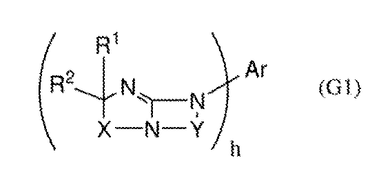
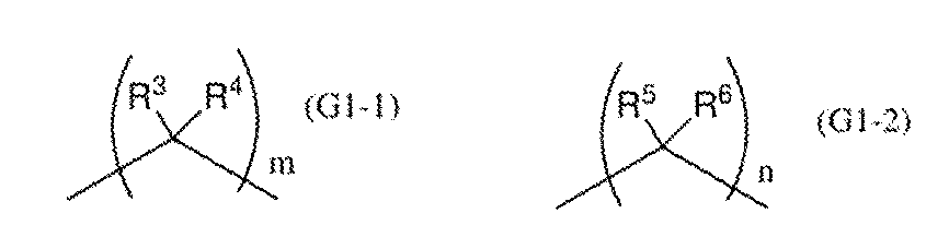
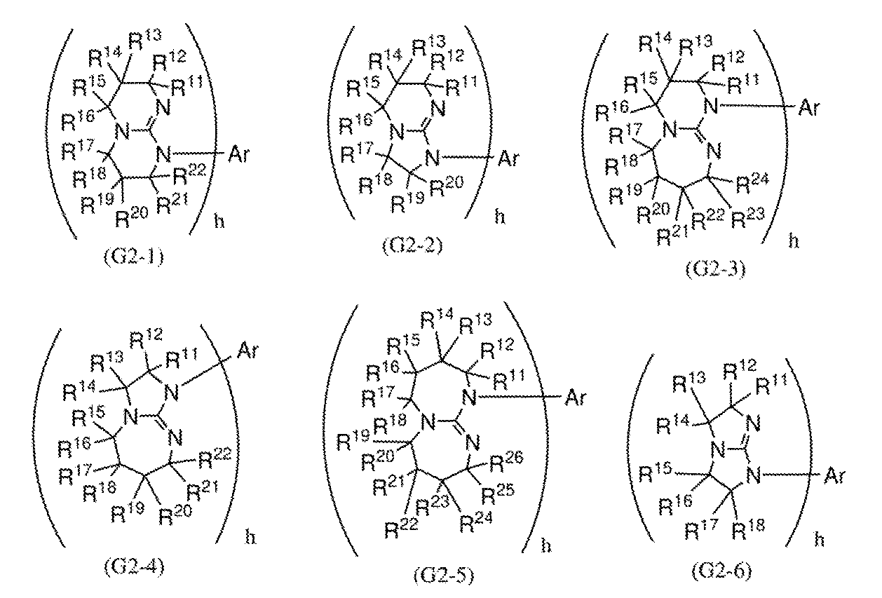
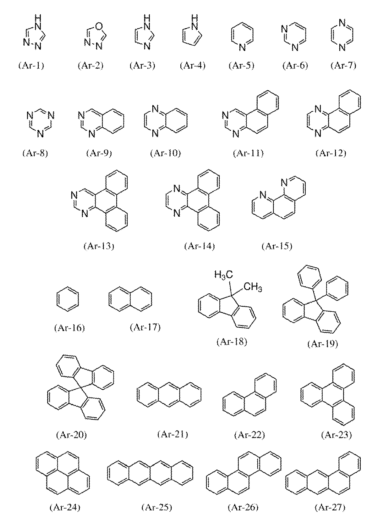

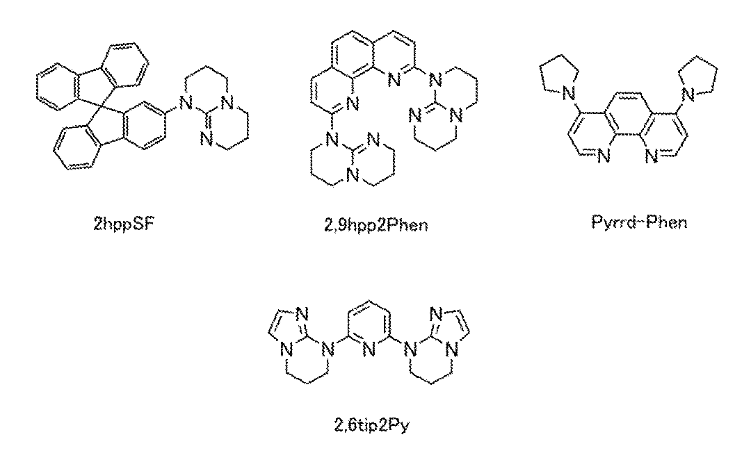
電子輸送性の高い物質を有機化合物ETMXに用いることができる。電子輸送性の高い物質とは、正孔よりも電子の移動度が高いものを指す。具体的には、電界強度V/cmの平方根が600における電子移動度が、1×10−7cm2/Vs以上好ましくは1×10−6cm2/Vs以上の電子移動度を有する物質が好ましい。また、電子輸送性の高い有機化合物としては、例えば複素芳香族化合物を用いることができる。なお、複素芳香族化合物とは、環の中に少なくとも2種類の異なる元素を含む環式化合物である。なお、環構造としては、3員環、4員環、5員環、6員環等が含まれるが、特に5員環、または、6員環が好ましく、含まれる元素としては、炭素の他に窒素、酸素、または硫黄などのいずれか一又は複数を含む複素芳香族化合物が好ましい。特に窒素を含む複素芳香族化合物(含窒素複素芳香族化合物)が好ましく、含窒素複素芳香族化合物、またはこれを含むπ電子不足型複素芳香環を有する有機化合物等の電子輸送性の高い材料(電子輸送性材料)を用いることが好ましい。
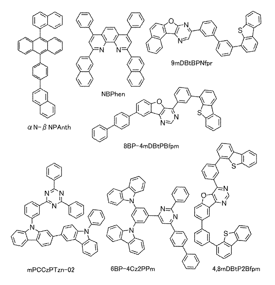
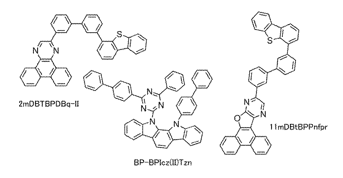
例えば、4より小さい酸解離定数pKaを有する材料を、有機化合物ETMXに用いることができる。例えば、4以上の酸解離定数pKaを有する有機化合物の水への溶解性と比較して、4より小さい酸解離定数pKaを有する有機化合物の水への溶解性は低い。また、4以上の酸解離定数pKaを有する有機化合物を有機化合物ETMXに用いる場合と比較して、4より小さい酸解離定数pKaを有する材料を有機化合物ETMXに用いると、層105Xの耐水性を向上することができる。また、作製工程において、層105Xが他の層から剥がれてしまう等の不具合の発生を抑制することができる。これにより、発光デバイスに欠陥を生じさせる不具合の発生を抑制することができる。
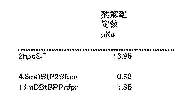
例えば、溶解度パラメータδにおいて、4.0MPa0.5以下の分極項δpを有する材料を、有機化合物ETMXに用いることができる。例えば、溶解度パラメータδにおいて、4.0MPa0.5より大きい分極項δpを有する有機化合物の水への溶解性と比較して、4.0MPa0.5以下の分極項δpを有する有機化合物の水への溶解性は低い。また、4より大きいδpを有する有機化合物を有機化合物ETMXに用いる場合と比較して、4.0MPa0.5以下の分極項δpを有する材料を有機化合物ETMXに用いると、層105Xの耐水性を向上することができる。また、作製工程において、層105Xが他の層から剥がれてしまう等の不具合の発生を抑制することができる。これにより、発光デバイスに欠陥を生じさせる不具合の発生を抑制することができる。


また、層105Xは、電子スピン共鳴(ESR:Electron Spin Resonance)法で観測されるシグナルが小さい、あるいはシグナルが観測されないことが好ましい。例えば、g値2.00付近に観測されるシグナルに起因するスピン密度が1×10¹⁷spins/cm3以下が好ましく、1×1016spins/cm3未満がより好ましい。
例えば、電子注入性を有する材料を、層105Xに用いることができる。また、層105Xを電子注入層ということができる。
例えば、アルカリ金属、アルカリ土類金属、希土類金属またはこれらの化合物(酸化物、ハロゲン化物、炭酸塩等)を、電子供与性を有する物質に用いることができる。または、テトラチアナフタセン(略称:TTN)、ニッケロセン、デカメチルニッケロセン等の有機化合物を、電子供与性を有する物質に用いることもできる。
また、複数種の物質を複合した材料を、電子注入性を有する材料に用いることができる。例えば、電子供与性を有する物質と電子輸送性を有する材料を、複合材料に用いることができる。
例えば、電界強度V/cmの平方根が600である条件において、電子移動度が1×10−7cm2/Vs以上、5×10−5cm2/Vs以下である材料を、電子輸送性を有する材料に好適に用いることができる。これにより、発光層への電子の注入量を制御することができる。または、発光層が電子過多の状態になることを防ぐことができる。
また、微結晶状態のアルカリ金属のフッ化物と電子輸送性を有する材料を、複合材料に用いることができる。または、微結晶状態のアルカリ土類金属のフッ化物と電子輸送性を有する材料を、複合材料に用いることができる。特に、アルカリ金属のフッ化物またはアルカリ土類金属のフッ化物を50wt%以上含む複合材料を好適に用いることができる。または、ビピリジン骨格を有する有機化合物を含む複合材料を好適に用いることができる。これにより、層105Xの屈折率を低下することができる。または、発光デバイス550Xの外部量子効率を向上することができる。
例えば、非共有電子対を備える第1の有機化合物および第1の金属を含む複合材料を、層105Xに用いることができる。また、第1の有機化合物の電子数と第1の金属の電子数の合計が奇数であると好ましい。また、第1の有機化合物1モルに対する第1の金属のモル比率は、好ましくは0.1以上10以下、より好ましくは0.2以上2以下、さらに好ましくは0.2以上0.8以下である。
例えば、電子輸送性を有する材料を、非共有電子対を備える有機化合物に用いることができる。例えば、電子不足型複素芳香環を有する化合物を用いることができる。具体的には、ピリジン環、ジアジン環(ピリミジン環、ピラジン環、ピリダジン環)、トリアジン環の少なくとも一つを有する化合物を用いることができる。これにより、発光デバイス550Xの駆動電圧を低減することができる。
例えば、非共有電子対を備える第1の有機化合物の電子数が偶数である場合、周期表における奇数の族である第1の金属および第1の有機化合物の複合材料を、層105Xに用いることができる。
例えば、カルシウムとアルミニウムの混合酸化物に電子を高濃度添加した物質等を、電子注入性を有する材料に用いることができる。
また、層105X1および層105X2を積層した構成を、層105Xに用いることができる(図1B参照)。例えば、層105X1は、層105X2およびユニット103Xの間に挟まれる。また、層105X2は電極552Xと接する。
例えば、層105Xの構成例1乃至層105Xの構成例3において説明した構成を層105X1に用いることができる。
例えば、電極552Xを形成する工程に対して安定な材料を層105X2に用いることができる。これにより、層105X2上に電極552Xを形成する際に、発光デバイスに与える損傷を減らすことができる。
有機化合物および無機化合物を、電子受容性を有する物質に用いることができる。
また、例えば、電子受容性を有する物質と正孔輸送性を有する材料を含む複合材料を層105X2に用いることができる。これにより、仕事関数に依らず、広い範囲の材料から、電極552Xに用いる材料を選ぶことができる。
また、例えば、層105X21および層105X22を積層した構成を、層105X2に用いることができる(図1C参照)。層105X21は有機化合物AMを含み、層105X22は有機化合物HTMを含む。なお、層105X22は層105X21と接すると好ましい。また、層105X21は電極552Xおよび層105X22の間に挟まれると好ましい。これにより、層105X2および電極552Xの間におけるキャリアの授受が円滑になる。また、発光デバイスの駆動電圧の上昇を抑制することができる。
また、例えば、層105X1、層105X2および層105X3を積層した構成を、層105Xに用いることができる(図1Bおよび図1C参照)。層105X1は、層105X3およびユニット103Xの間に挟まれ、層105X3は、層105X2および層105X1の間に挟まれる。例えば、層105X2は電極552Xと接する。
本実施の形態では、本発明の一態様の発光デバイス550Xの構成について、図1Aを参照しながら説明する。
本実施の形態で説明する発光デバイス550Xは、電極551Xと、電極552Xと、ユニット103Xと、を有する。電極552Xは、電極551Xと重なり、ユニット103Xは、電極552Xおよび電極551Xの間に挟まれる。
ユニット103Xは単層構造または積層構造を備える。例えば、ユニット103Xは、層111X、層112Xおよび層113Xを備える(図1A参照)。ユニット103Xは光ELXを射出する機能を備える。
例えば、正孔輸送性を有する材料を、層112Xに用いることができる。また、層112Xを正孔輸送層ということができる。なお、層111Xに含まれる発光性の材料より大きいバンドギャップを備える材料を、層112Xに用いる構成が好ましい。これにより、層111Xにおいて生じる励起子から層112Xへのエネルギー移動を、抑制することができる。
正孔移動度が、1×10⁻⁶cm2/Vs以上である材料を、正孔輸送性を有する材料に好適に用いることができる。
例えば、電子輸送性を有する材料、アントラセン骨格を有する材料および混合材料等を、層113Xに用いることができる。また、層113Xを電子輸送層ということができる。なお、層111Xに含まれる発光性の材料より大きいバンドギャップを有する材料を、層113Xに用いる構成が好ましい。これにより、層111Xにおいて生じる励起子から層113Xへのエネルギー移動を、抑制することができる。
例えば、電界強度V/cmの平方根が600である条件において、電子移動度が1×10−7cm2/Vs以上、5×10−5cm2/Vs以下である材料を、電子輸送性を有する材料に好適に用いることができる。これにより、電子輸送層における電子の輸送性を抑制することができる。または、発光層への電子の注入量を制御することができる。または、発光層が電子過多の状態になることを防ぐことができる。
アントラセン骨格を有する有機化合物を、層113Xに用いることができる。特に、アントラセン骨格と複素環骨格の両方を含む有機化合物を好適に用いることができる。
また、複数種の物質を混合した材料を、層113Xに用いることができる。具体的には、アルカリ金属、アルカリ金属化合物またはアルカリ金属錯体と、電子輸送性を有する物質とを含む混合材料を、層113Xに用いることができる。なお、電子輸送性を有する材料のHOMO準位が−6.0eV以上であるとより好ましい。
例えば、発光性の材料、または発光性の材料およびホスト材料を、層111Xに用いることができる。また、層111Xを発光層ということができる。なお、正孔と電子が再結合する領域に層111Xを配置する構成が好ましい。これにより、キャリアの再結合により生じるエネルギーを、効率よく光にして射出することができる。
蛍光発光物質を層111Xに用いることができる。例えば、以下に例示する蛍光発光物質を層111Xに用いることができる。なお、これに限定されず、さまざまな公知の蛍光性発光物質を層111Xに用いることができる。
りん光発光物質を層111Xに用いることができる。例えば、以下に例示するりん光発光物質を層111Xに用いることができる。なお、これに限定されず、さまざまな公知のりん光性発光物質を層111Xに用いることができる。
4H−トリアゾール骨格を有する有機金属イリジウム錯体等としては、例えば、トリス{2−[5−(2−メチルフェニル)−4−(2,6−ジメチルフェニル)−4H−1,2,4−トリアゾール−3−イル−κN2]フェニル−κC}イリジウム(III)(略称:[Ir(mpptz−dmp)3])、トリス(5−メチル−3,4−ジフェニル−4H−1,2,4−トリアゾラト)イリジウム(III)(略称:[Ir(Mptz)3])、トリス[4−(3−ビフェニル)−5−イソプロピル−3−フェニル−4H−1,2,4−トリアゾラト]イリジウム(III)(略称:[Ir(iPrptz−3b)3])、等を用いることができる。
ピリミジン骨格を有する有機金属イリジウム錯体等としては、例えば、トリス(4−メチル−6−フェニルピリミジナト)イリジウム(III)(略称:[Ir(mppm)3])、トリス(4−t−ブチル−6−フェニルピリミジナト)イリジウム(III)(略称:[Ir(tBuppm)3])、(アセチルアセトナト)ビス(6−メチル−4−フェニルピリミジナト)イリジウム(III)(略称:[Ir(mppm)2(acac)])、(アセチルアセトナト)ビス(6−tert−ブチル−4−フェニルピリミジナト)イリジウム(III)(略称:[Ir(tBuppm)2(acac)])、(アセチルアセトナト)ビス[6−(2−ノルボルニル)−4−フェニルピリミジナト]イリジウム(III)(略称:[Ir(nbppm)2(acac)])、(アセチルアセトナト)ビス[5−メチル−6−(2−メチルフェニル)−4−フェニルピリミジナト]イリジウム(III)(略称:[Ir(mpmppm)2(acac)])、(アセチルアセトナト)ビス(4,6−ジフェニルピリミジナト)イリジウム(III)(略称:[Ir(dppm)2(acac)])、等を用いることができる。
ピリミジン骨格を有する有機金属イリジウム錯体等としては、例えば、(ジイソブチリルメタナト)ビス[4,6−ビス(3−メチルフェニル)ピリミジナト]イリジウム(III)(略称:[Ir(5mdppm)2(dibm)])、ビス[4,6−ビス(3−メチルフェニル)ピリミジナト](ジピバロイルメタナト)イリジウム(III)(略称:[Ir(5mdppm)2(dpm)])、ビス[4,6−ジ(ナフタレン−1−イル)ピリミジナト](ジピバロイルメタナト)イリジウム(III)(略称:[Ir(d1npm)2(dpm)])、等を用いることができる。
TADF材料を層111Xに用いることができる。TADF材料を発光物質として用いる場合、ホスト材料のS1準位はTADF材料のS1準位より高い方が好ましい。また、ホスト材料のT1準位はTADF材料のT1準位より高いことが好ましい。
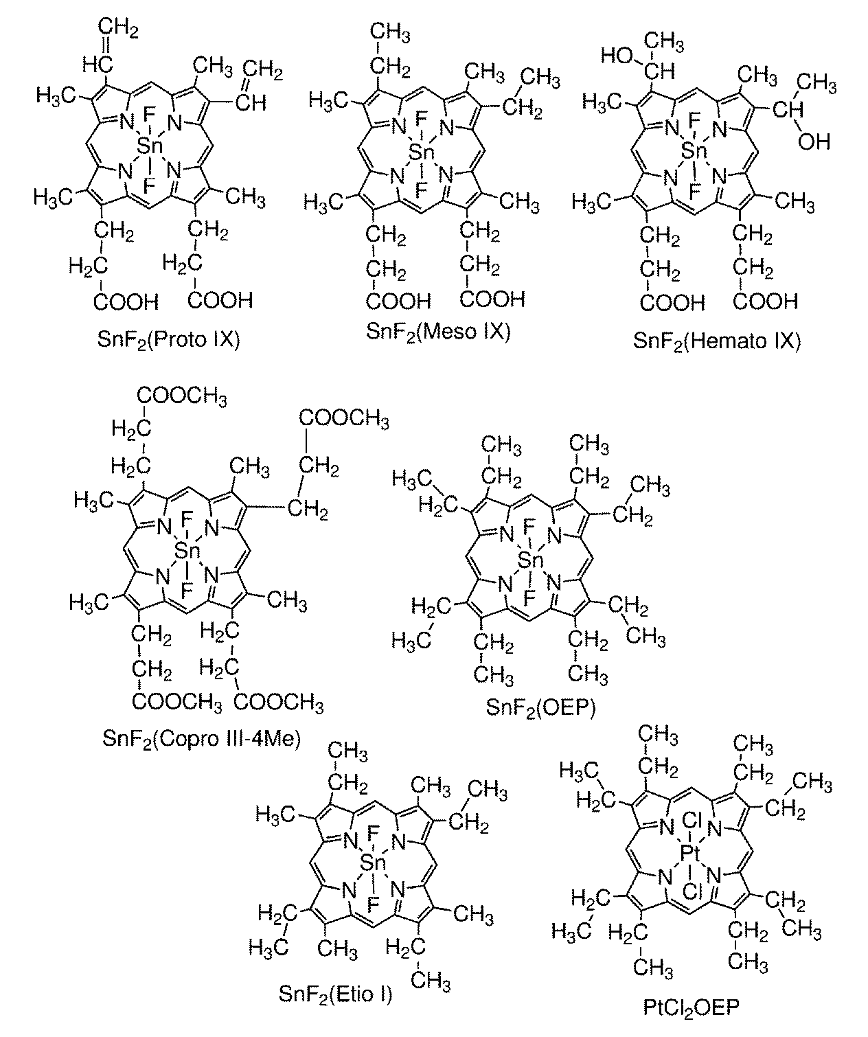

キャリア輸送性を備える材料をホスト材料に用いることができる。例えば、正孔輸送性を有する材料、電子輸送性を有する材料、熱活性化遅延蛍光(TADF:Thermally Activated Delayed Fluorescence)を示す物質、アントラセン骨格を有する材料および混合材料等をホスト材料に用いることができる。なお、層111Xに含まれる発光性の材料より大きいバンドギャップを備える材料を、ホスト材料に用いる構成が好ましい。これにより、層111Xにおいて生じる励起子からホスト材料へのエネルギー移動を、抑制することができる。
正孔移動度が、1×10⁻⁶cm2/Vs以上である材料を、正孔輸送性を有する材料に好適に用いることができる。例えば、層112Xに用いることができる正孔輸送性を有する材料を、層111Xに用いることができる。
金属錯体またはπ電子不足型複素芳香環骨格を有する有機化合物を、電子輸送性を有する材料に用いることができる。例えば、層113Xに用いることができる電子輸送性を有する材料を、層111Xに用いることができる。
アントラセン骨格を有する有機化合物を、ホスト材料に用いることができる。特に、発光物質に蛍光発光物質を用いる場合において、アントラセン骨格を有する有機化合物は好適である。これにより、発光効率および耐久性が良好な発光デバイスを実現することができる。
TADF材料をホスト材料に用いることができる。TADF材料をホスト材料に用いると、TADF材料で生成した三重項励起エネルギーを、逆項間交差によって一重項励起エネルギーに変換することができる。さらに、励起エネルギーを発光物質に移動することができる。換言すれば、TADF材料はエネルギードナーとして機能し、発光物質はエネルギーアクセプターとして機能する。これにより、発光デバイスの発光効率を高めることができる。
また、複数種の物質を混合した材料を、ホスト材料に用いることができる。例えば、電子輸送性を有する材料と正孔輸送性を有する材料を、混合材料に用いることができる。混合材料に含まれる電子輸送性を有する材料に対する正孔輸送性を有する材料の重量比の値を、(正孔輸送性を有する材料/電子輸送性を有する材料)=(1/19)以上(19/1)以下とすればよい。これにより、層111Xのキャリア輸送性を容易に調整することができる。また、再結合領域の制御も簡便に行うことができる。
りん光発光物質を混合した材料を、ホスト材料に用いることができる。りん光発光物質は、発光物質として蛍光発光物質を用いる際に蛍光発光物質へ励起エネルギーを供与するエネルギードナーとして用いることができる。
励起錯体を形成する材料を含む混合材料を、ホスト材料に用いることができる。例えば、形成される励起錯体の発光スペクトルが、発光物質の最も低エネルギー側の吸収帯の波長と重なる材料を、ホスト材料に用いることができる。これにより、エネルギー移動がスムーズとなり、発光効率を向上することができる。または、駆動電圧を抑制することができる。このような構成とすることにより、励起錯体から発光物質(燐光材料)へのエネルギー移動であるExTET(Exciplex−Triplet Energy Transfer)を用いた発光を効率よく得ることができる。
本実施の形態では、本発明の一態様の発光デバイス550Xの構成について、図1Aを参照しながら説明する。
本実施の形態で説明する発光デバイス550Xは、電極551Xと、電極552Xと、ユニット103Xと、層104Xと、を有する(図1A参照)。
例えば、実施の形態1において説明する電極552Xに用いることができる材料を、電極551Xに用いることができる。
例えば、正孔注入性を有する材料を、層104Xに用いることができる。また、層104Xを正孔注入層ということができる。
例えば、電子受容性を有する物質を、層104Xに用いることができる。または、複数種の物質を含む複合材料を、層104Xに用いることができる。
本実施の形態では、本発明の一態様の発光デバイス550Xの構成について、図2を参照しながら説明する。
本実施の形態で説明する発光デバイス550Xは、電極551Xと、電極552Xと、ユニット103Xと、中間層106Xと、ユニット103X2と、を有する(図2参照)。また、発光デバイス550Xは、層105Xおよび層104Xを有する。
ユニット103X2は単層構造または積層構造を備える。例えば、ユニット103X2は、層111X2、層112X2および層113X2を備える。なお、ユニット103X2は光ELX2を射出する機能を備える。
また、ユニット103Xとは異なる構成をユニット103X2に用いることができる。例えば、ユニット103Xの発光色とは色相が異なる光を射出する構成を、ユニット103X2に用いることができる。
中間層106Xは、陽極側に電子を供給し、陰極側に正孔を供給する機能を備える。また、中間層106Xは、ユニット103Xまたはユニット103X2の一方に電子を供給し、他方に正孔を供給する機能を備える。
例えば、層106X1および層106X2を積層した構成を、中間層106Xに用いることができる。層106X1は、電極552Xおよびユニット103Xの間に挟まれる領域を備え、層106X2は、層106X1およびユニット103Xの間に挟まれる領域を備える。
例えば、実施の形態1において説明する層105X2に用いることができる構成を層106X1に用いることができる。
例えば、実施の形態1において説明する層105X1に用いることができる材料を、層106X2に用いることができる。
層106X1、層106X2および層106X3を積層した構成を、中間層106Xに用いることができる。層106X3は、層106X2および層106X1の間に挟まれる領域を備える。
例えば、電子輸送性を有する材料を層106X3に用いることができる。また、層106X3を電子リレー層ということができる。層106X3を用いると、層106X3の陽極側に接する層を、層106X3の陰極側に接する層から遠ざけることができる。層106X3の陽極側に接する層と、層106X3の陰極側に接する層の間の相互作用を軽減することができる。層106X3の陽極側に接する層に電子をスムーズに供給することができる。
例えば、乾式法、湿式法、蒸着法、液滴吐出法、塗布法または印刷法等を用いて、電極551X、電極552X、ユニット103X、中間層106X、およびユニット103X2の各層を形成することができる。また、異なる方法を各構成の形成に用いることができる。
本実施の形態では、本発明の一態様の表示装置の構成について、図3乃至図6を参照しながら説明する。
本実施の形態で説明する表示装置700は、一組の画素703を有する(図3A参照)。また、表示装置700は、基板510および機能層520を有する。
また、本実施の形態で説明する表示装置700は、発光デバイス550Aと、発光デバイス550Bと、導電膜552_2と、を有する(図4A参照)。
発光デバイス550Aは、電極551A、電極552A、ユニット103Aおよび層104Aを備える。
発光デバイス550Bは、電極551B、電極552B、ユニット103Bおよび層104Bを備える(図4A参照)。
発光デバイス550Cは、電極551C、電極552C、ユニット103Cおよび層104Cを備える(図4A参照)。
また、本実施の形態で説明する表示装置700は、層528を有する(図4Aおよび図5A参照)。
層528は、開口部528Aおよび開口部528Bを備え、開口部528Aは電極551Aと重なり、開口部528Bは、電極551Bと重なる(図4B参照)。また、層528は開口部528Cを備え、開口部528Cは電極551Cと重なる。
また、例えば、電極551Aの側面を覆う膜を、層528に用いることができる(図5B参照)。例えば、電極551Aを形成した後に絶縁性の膜を形成し、次いで、マスクを用いることなく異方性エッチングを当該絶縁性の膜に施す方法により、層528を形成することができる。これにより、製造工程を簡略にすることができる。また、歩留まりの向上を期待できる。また、製造コストを低減することができる。
また、例えば、間隙551ABに形成される段差と同じ厚さを備える層を、層528に用いることができる(図5C参照)。例えば、間隙551ABに形成される段差を埋める厚さの絶縁膜を形成し、化学機械研磨(CMP:Chemical mechanical polishing)法を用いて当該絶縁膜の不要な部分を取り除き、層528を所定の形状に形成することができる。
また、本実施の形態で説明する表示装置700は、発光デバイス550Aが層105Aを備え、発光デバイス550Bが層105Bを備える(図4A参照)。
層105Aは、電極552Aおよびユニット103Aの間に挟まれる。層105Aは電極552Aと接し、層105Aは電子注入性を備える。
また、層105Aは、有機化合物OCAおよび有機化合物ETMAを含む。なお、実施の形態1において説明する有機化合物OCAおよび有機化合物ETMAを、層105Aに用いることができる。
層105Bは、電極552Bおよびユニット103Bの間に挟まれる。層105Bは電極552Bと接し、層105Bは電子注入性を備える。また、層105Bは、層105Aとの間に間隙105ABを備え、間隙105ABは間隙551ABと重なる。
また、本実施の形態で説明する表示装置700は、層529_2を有する(図4Aおよび図4B参照)。
層529_2は、導電膜552_2および間隙551ABの間に挟まれ、層529_2は、導電膜552_2と接する。
また、本実施の形態で説明する表示装置700は、層529_1を有する(図4Aおよび図4B参照)。
層529_1は、層529_2および間隙551ABの間に挟まれ、層529_1は、電極552Aおよび電極552Bと接する。
また、本実施の形態で図6Aおよび図6Bを用いて説明する表示装置700は、発光デバイス550Aの構成が異なる点、発光デバイス550Bの構成が異なる点、発光デバイス550Cの構成が異なる点が、図4Aおよび図4Bを用いて説明する表示装置700とは異なる。ここでは、異なる部分について詳細に説明し、同じ構成を備える部分については、上記の説明を援用する。
発光デバイス550Aは、電極551A、電極552A、ユニット103A、ユニット103A2、中間層106Aおよび層105Aを備える(図6Aおよび図6B参照)。
発光デバイス550Bは、電極551B、電極552B、ユニット103B、ユニット103B2、中間層106Bおよび層105Bを備える(図6A参照)。
発光デバイス550Cは、電極551C、電極552C、ユニット103C、ユニット103C2、中間層106Cおよび層105Cを備える。
層528は、導電膜552_2および絶縁層521の間に挟まれる領域を備える(図6A参照)。また、層528は、電極552Aおよび電極551Aの間に挟まれる領域を備える。また、層528は、中間層106Aおよび電極551Aの間に挟まれる領域を備える。また、層528は、層104Aおよび電極551Aの間に挟まれる領域を備える。
本実施の形態では、本発明の一態様の表示装置の作製方法について、図7乃至図19を参照しながら説明する。
第1のステップ乃至第3のステップは、反射膜REFA、反射膜REFB、反射膜REFC、電極551A、電極551B、電極551Cおよび層528を形成するステップである(図7参照)。
下記のステップを有する方法を用いて、本実施例で説明する発光デバイス550Aを作製する。
第1のステップにおいて、絶縁層521の上に反射膜REFA、反射膜REFBおよび反射膜REFCを形成する(図7参照)。具体的には、導電膜を積層し、フォトリソグラフィ法を用いて所定の形状に加工する。
第2のステップにおいて、反射膜REFAの上に電極551Aを形成し、反射膜REFBの上に電極551Bを形成し、反射膜REFCの上に電極551Cを形成する。具体的には、透光性を有する導電膜を形成し、フォトリソグラフィ法を用いて所定の形状に加工する。なお、電極551Bは電極551Aと隣接し、電極551Bは、電極551Aとの間に間隙551ABを備える。
第3のステップにおいて、複数の開口部を備える層528を形成する。具体的には、後に層528になる絶縁膜を形成し、フォトリソグラフィ法を用いて所定の形状に加工する。なお、層528は電極551Aと重なる開口部と、電極551Bと重なる開口部と、電極551Cと重なる開口部とを備える。また、層528は、電極551Aの端部、電極551Bの端部および電極551Cの端部を覆い、間隙551ABと重なる。
第4のステップにおいて、電極551Aの上に、後に層104Aになる膜104aを形成する(図8参照)。例えば、抵抗加熱法を用いて材料を蒸着する。
第5のステップにおいて、膜104aの上に、後にユニット103Aになる積層膜103aを形成する。例えば、抵抗加熱法を用いて材料を蒸着する。
第6のステップにおいて、積層膜103aの上に、後に層105Aになる膜105aを形成する。例えば、抵抗加熱法を用いて材料を蒸着する。
第7のステップにおいて、膜105aの上に、後に電極552Aになる膜552aを形成する。具体的には、膜105aまで形成したワークピースを真空蒸着装置から取り出して、原子層堆積法成膜装置に導入し、原子層堆積法を用いて材料を成膜する。なお、例えば、膜552aはAZOを含み、1nm以上50nm以下、好ましくは3nm以上45nm以下、より好ましくは5nm以上40nm以下の厚さを備える。また、膜552aが1nm以上の厚さを有すると、例えば、第8のステップにおいて、スパッタリング法を用いて膜SCRaを成膜する際に、膜105aまたは積層膜103aに与える損傷を少なくできる。また、発光デバイスの特性を損ないにくい。また、膜552aが3nm以上より好ましくは5nm以上の厚さを有すると、例えば、第9−1のステップにおいて、エッチング法を用いて層SCRAを形成する際にエッチングストッパーとして機能し、許容できる加工工程のばらつきの範囲を広くすることができる。また、膜552aが50nm以下の厚さを有すると、例えば、原子層堆積法を用いて成膜する時間を短縮することができる。また、膜552aが40nm以下の厚さを有すると、透光性に優れ、優れた特性の発光デバイスを提供することができる。また、第9−2のステップにおいて、エッチング法を用いて電極552Aを容易に形成することができる。
第8のステップにおいて、膜552aの上に、後に層SCRAになる膜SCRaを形成する。具体的には、膜552aまで形成したワークピースを原子層堆積法成膜装置から取り出して、スパッタリング装置に導入し、スパッタリング法を用いて材料を成膜する。なお、例えば、50nmの厚さを備えるタングステンを含む膜を用いることができる。
第9−1のステップにおいて、膜SCRaを所定の形状に加工して、層SCRAを形成する(図9参照)。具体的には、膜SCRaを形成したワークピースをスパッタリング装置から取り出して、膜SCRaの上にレジストRESを形成する。次いで、レジストRESおよびエッチング法を用いて、電極551Aと重なる部分を残し、不要な部分をエッチング加工する。なお、層SCRAを形成したあと、例えば、酸素を含むガスをエッチングガスに用いて、レジストRESを取り除く。また、膜552aに金属酸化物を用いる場合、膜552aから酸素を奪う材料を、膜SCRaに好適に用いることができる。これにより、膜552aに酸素欠損に由来する準位が形成され、膜552aの導電率を高めることができる。また、酸化に伴い、可視光に対する透過率が高くなる材料を、膜SCRaに好適に用いることができる。これにより、発光デバイス550Aから効率よく光を取り出すことができる。例えば、チタンを含む膜を膜SCRaに用いることができる。
第9−2のステップにおいて、膜552aを所定の形状に加工して、電極552Aを形成する(図10参照)。具体的には、層SCRAおよびエッチング法を用いて、電極551Aと重なる部分を残し、不要な部分をエッチング加工する。
第9−3のステップにおいて、膜105a、積層膜103aおよび膜104aを所定の形状に加工して、層105A、ユニット103Aおよび層104Aを形成する(図11参照)。具体的には、電極551Aと重なる部分を残し、不要な部分をエッチング加工する。なお、例えば、酸素を含むガスをエッチングガスに用いることができる。また、層SCRAは、ハードマスクとして機能する。
第10のステップにおいて、層SCRAを取り除く(図16参照)。具体的には、ドライエッチング法を用いて、エッチング加工する。なお、仕掛品が、層SCRA、層SCRBおよび層SCRCを備える場合、第10のステップにおいて、層SCRA、層SCRBおよび層SCRCを取り除く。
第11−1のステップにおいて、後に層529_1になる絶縁膜を形成する。具体的には、電極552Aの上面および層105A、ユニット103A並びに層104Aの側面を覆うように、原子層堆積法を用いて後に層529_1になる絶縁膜を形成する。なお、例えば、10nmの厚さを備える、酸化アルミニウム(略称:ALOX)を含む膜を用いることができる。
第11−2のステップにおいて、層529_2を所定の形状に形成する(図17参照)。具体的には、感光性樹脂を層529_2に用いることができる。また、電極551Aと重なる部分を除去して開口部529_2Aを形成し、電極551Bと重なる部分を除去して開口部529_2Bを形成し、電極551Aおよび電極551Aに隣接する電極551Bの間を残す。また、電極551Cと重なる部分を除去して開口部529_2Cを形成する。
第11−3のステップにおいて、層529_1を所定の形状に形成する(図18参照)。具体的には、層529_2をレジストに用いて、開口部529_2Aと重なる開口部と、開口部529_2Bと重なる開口部と、開口部529_2Cと重なる開口部とを、層529_1に形成する。例えば、ウェットエッチング法を用いることができる。具体的には、フッ酸(HF)を含む水溶液、リン酸を含む水溶液、硝酸を含む水溶液または水酸化テトラメチルアンモニウム(略称:TMAH)を含む水溶液をエッチング液に用いることができる。これにより開口部において、電極552Aが露出する。
第12のステップにおいて、電極552Aの上に導電膜552_2を形成する(図19参照)。例えば、抵抗加熱法を用いて材料を蒸着する。
第13のステップにおいて、導電膜552_2の上に層CAPを形成する。
下記のステップを有する方法を用いて、本実施例で説明する発光デバイス550Bを作製する。具体的には、発光デバイス550Aの第1のステップ乃至第9−3のステップと同様の方法を用いて、発光デバイス550Bを作製する。なお、発光デバイス550Bの反射膜REFBおよび電極551Bは、発光デバイス550Aの作製方法の第1のステップ乃至第3のステップにおいて形成される。
第4のステップにおいて、電極551Bの上に、後に層104Bになる膜104bを形成する。例えば、抵抗加熱法を用いて材料を蒸着する。
第5のステップにおいて、膜104bの上に、後にユニット103Bになる積層膜103bを形成する。例えば、抵抗加熱法を用いて材料を蒸着する。
第6のステップにおいて、積層膜103bの上に、後に層105Bになる膜105bを形成する。例えば、抵抗加熱法を用いて材料を蒸着する。
第7のステップにおいて、膜105bの上に、後に電極552Bになる膜552bを形成する。具体的には、膜105bまで形成したワークピースを真空蒸着装置から取り出して、原子層堆積法成膜装置に導入し、原子層堆積法を用いて材料を成膜する。なお、例えば、膜552bはAZOを含み、1nm以上50nm以下、好ましくは3nm以上45nm以下、より好ましくは5nm以上40nm以下の厚さを備える。
第8のステップにおいて、膜552bの上に、後に層SCRBになる膜を形成する。具体的には、膜552bまで形成したワークピースを原子層堆積法成膜装置から取り出して、スパッタリング装置に導入し、スパッタリング法を用いて材料を成膜する。なお、例えば、50nmの厚さを備えるタングステンを含む膜を、後に層SCRBになる膜に用いることができる。
第9−1のステップにおいて、後に層SCRBになる膜を所定の形状に加工して、層SCRBを形成する(図12参照)。具体的には、後に層SCRBになる膜を形成したワークピースをスパッタリング装置から取り出して、後に層SCRBになる膜の上にレジストRESを形成する。次いで、レジストRESおよびエッチング法を用いて、電極551Bと重なる部分を残し、不要な部分をエッチング加工する。なお、層SCRBを形成したあと、例えば、酸素を含むガスをエッチングガスに用いて、レジストRESを取り除く。
第9−2のステップにおいて、膜552bを所定の形状に加工して、電極552Bを形成する(図13参照)。具体的には、層SCRBおよびエッチング法を用いて、電極551Bと重なる部分を残し、不要な部分をエッチング加工する。
第9−3のステップにおいて、膜105b、積層膜103bおよび膜104bを所定の形状に加工して、層105B、ユニット103Bおよび層104Bを形成する(図14参照)。具体的には、電極551Bと重なる部分を残し、不要な部分をエッチング加工する。なお、例えば、酸素を含むガスをエッチングガスに用いることができる。また、層SCRBは、ハードマスクとして機能する。
下記のステップを有する方法を用いて、本実施例で説明する発光デバイス550Cを作製する。具体的には、発光デバイス550Aの第1のステップ乃至第9−3のステップと同様の方法を用いて、発光デバイス550Cを作製する。なお、発光デバイス550Cの反射膜REFCおよび電極551Cは、発光デバイス550Aの作製方法の第1のステップ乃至第3のステップにおいて形成される。
第4のステップにおいて、電極551Cの上に、後に層104Cになる膜を形成する。例えば、抵抗加熱法を用いて材料を蒸着する。
第5のステップにおいて、後に層104Cになる膜の上に、後にユニット103Cになる積層膜を形成する。例えば、抵抗加熱法を用いて材料を蒸着する。
第6のステップにおいて、後にユニット103Cになる積層膜の上に、後に層105Cになる膜を形成する。例えば、抵抗加熱法を用いて材料を蒸着する。
第7のステップにおいて、後に層105Cになる膜の上に、後に電極552Cになる膜を形成する。具体的には、後に層105Cになる膜まで形成したワークピースを真空蒸着装置から取り出して、原子層堆積法成膜装置に導入し、原子層堆積法を用いて材料を成膜する。なお、例えば、後に電極552Cになる膜はAZOを含み、1nm以上50nm以下、好ましくは3nm以上45nm以下、より好ましくは5nm以上40nm以下の厚さを備える。
第8のステップにおいて、後に電極552Cになる膜の上に、後に層SCRCになる膜を形成する。具体的には、後に電極552Cになる膜まで形成したワークピースを原子層堆積法成膜装置から取り出して、スパッタリング装置に導入し、スパッタリング法を用いて材料を成膜する。なお、例えば、50nmの厚さを備えタングステンを含む膜を用いることができる。
第9−1のステップにおいて、後に層SCRCになる膜を所定の形状に加工して、層SCRCを形成する。具体的には、後に層SCRCになる膜を形成したワークピースをスパッタリング装置から取り出して、後に層SCRCになる膜の上にレジストを形成する。次いで、レジストおよびエッチング法を用いて、電極551Cと重なる部分を残し、不要な部分をエッチング加工する。なお、層SCRCを形成したあと、例えば、酸素を含むガスをエッチングガスに用いて、レジストを取り除く。
第9−2のステップにおいて、後に電極552Cになる膜を所定の形状に加工して、電極552Cを形成する。具体的には、層SCRCおよびエッチング法を用いて、電極551Cと重なる部分を残し、不要な部分をエッチング加工する。
第9−3のステップにおいて、後に層105Cになる膜、後にユニット103Cになる積層膜および後に層104Cになる膜を所定の形状に加工して、層105C、ユニット103Cおよび層104Cを形成する(図15参照)。具体的には、電極551Cと重なる部分を残し、不要な部分をエッチング加工する。なお、例えば、酸素を含むガスをエッチングガスに用いることができる。また、層SCRCは、ハードマスクとして機能する。
本実施の形態では、本発明の一態様の表示装置の構成について、図20および図21を参照しながら説明する。
本発明の一態様の表示装置700は、領域731を有する(図20A参照)。領域731は、一組の画素703(i,j)を備える。
一組の画素703(i,j)は、画素702A(i,j)、画素702B(i,j)および画素702C(i,j)を備える(図20Bおよび図20C参照)。
また、本発明の一態様の表示装置700は、機能層540と、機能層520と、を有する(図20C参照)。機能層540は機能層520と重なる。
また、本発明の一態様の表示装置700は、駆動回路GDおよび駆動回路SDを有する(図20A参照)。
駆動回路GDは、第1の選択信号および第2の選択信号を供給する。
駆動回路SDは、第1の制御信号および第2の制御信号を供給する。
配線は、導電膜G1(i)、導電膜G2(i)、導電膜S1(j)、導電膜S2(j)、導電膜ANO、導電膜VCOM2および導電膜V0を含む(図21参照)。
画素回路530A(i,j)は、導電膜G1(i)および導電膜S1(j)と電気的に接続される。導電膜G1(i)は第1の選択信号を供給し、導電膜S1(j)は、第1の制御信号を供給する。
画素回路530A(i,j)は、スイッチSW21、スイッチSW22、トランジスタM21、容量C21およびノードN21を備える。
画素回路530A(i,j)は、スイッチSW23、ノードN22および容量C22を備える。
本実施の形態では、本発明の一態様の表示モジュールについて説明する。
図22は、表示モジュール280の構成を説明する斜視図である。
図23Aは、表示装置100Aの構成を説明する断面図である。例えば、表示モジュール280の表示装置100に用いることができる。基板301は、図22における基板71に相当する。
トランジスタ310は、導電層311、一対の低抵抗領域312、絶縁層313、及び絶縁層314を有し、基板301の一部にチャネルを形成する。導電層311は、ゲート電極として機能する。絶縁層313は、基板301と導電層311の間に位置し、ゲート絶縁層として機能する。基板301は不純物がドープされた一対の低抵抗領域312を備える。なお、当該領域は、ソース及びドレインとして機能する。導電層311の側面は、絶縁層314に覆われている。
容量240は、導電層241、導電層245および絶縁層243を有し、絶縁層243は、導電層241および導電層245の間に位置する。導電層241は、容量240の一方の電極として機能し、導電層245は、容量240の他方の電極として機能し、絶縁層243は、容量240の誘電体として機能する。
表示装置100Aは、絶縁層255a、絶縁層255bおよび絶縁層255cを備え、絶縁層255bは、絶縁層255aおよび絶縁層255cの間に位置する。
発光デバイス61R、発光デバイス61G、及び発光デバイス61Bは、絶縁層255c上に設けられる。例えば、実施の形態1乃至実施の形態4において説明する発光デバイスを、発光デバイス61R、発光デバイス61G、及び発光デバイス61Bに適用することができる。発光デバイス61Rは光81Rを射出し、発光デバイス61Gは光81Gを射出し、発光デバイス61Bは光81Bを射出する。また、発光デバイスは共通層174を有する。
保護層271および絶縁層278は隣接する発光デバイス、例えば、発光デバイス61Rおよび発光デバイス61Gの間に位置し、絶縁層278は保護層271上に設けられる。また、発光デバイス61R、発光デバイス61G、及び発光デバイス61B上には保護層273が設けられる。
基板120は、図22における基板73に相当する。なお、例えば、遮光層を基板120の接着層122側の面に設けることができる。また、各種光学部材を基板120の外側に配置できる。
図23Bは、表示装置100Bの構成を説明する断面図である。表示装置100Bは、例えば、表示モジュール280の表示装置100に用いることができる(図22参照)。
図24は、表示装置100Cの構成を説明する断面図である。表示装置100Cは、例えば、表示モジュール280の表示装置100に用いることができる(図22参照)。なお、以降の表示装置の説明では、先に説明した表示装置と同様の部分については説明を省略することがある。
絶縁層345は基板301Bの下面に接し、絶縁層346は絶縁層261の上に位置する。例えば、保護層273に用いることができる無機絶縁膜を、絶縁層345、及び絶縁層346に用いることができる。絶縁層345、及び絶縁層346は、保護層として機能し、不純物が基板301B及び基板301Aに拡散する現象を抑制することができる。
プラグ343は、基板301B及び絶縁層345を貫通する。絶縁層344は、プラグ343の側面を覆う。例えば、保護層273に用いることができる無機絶縁膜を絶縁層344に用いることができる。絶縁層344は保護層として機能し、不純物が基板301Bに拡散する現象を抑制することができる。
導電層342は、絶縁層345および絶縁層346の間に位置する。また、導電層342は絶縁層335に埋め込まれ、導電層342および絶縁層335で構成される面が平坦化されていると好ましい。なお、導電層342はプラグ343と電気的に接続される。
導電層341は、絶縁層346および絶縁層335の間に位置する。また、導電層341は絶縁層336に埋め込まれ、導電層341および絶縁層336で構成される面が平坦化されていると好ましい。導電層341は、導電層342と接合される。これにより、基板301Aは基板301Bと電気的に接続される。
図25は、表示装置100Dの構成を説明する断面図である。表示装置100Dは、例えば、表示モジュール280の表示装置100に用いることができる(図22参照)。
図26は、表示装置100Eの構成を説明する断面図である。表示装置100Eは、例えば、表示モジュール280の表示装置100に用いることができる(図22参照)。基板331は、図22における基板71に相当する。絶縁性基板又は半導体基板を基板331に用いることができる。表示装置100Eはトランジスタ320を有する。なお、トランジスタの構成がOSトランジスタである点において、表示装置100Eは表示装置100Aと相違する。
絶縁層332は基板331上に設けられる。例えば、酸化シリコン膜よりも水素又は酸素が拡散しにくい膜を、絶縁層332に用いることができる。具体的には、酸化アルミニウム膜、酸化ハフニウム膜、又は窒化シリコン膜等を絶縁層332に用いることができる。これにより、絶縁層332は、基板331から水又は水素等の不純物がトランジスタ320に拡散する現象を防ぐことができる。また、半導体層321から絶縁層332側に酸素が脱離することを防ぐことができる。
トランジスタ320は、半導体層321、絶縁層323、導電層324、一対の導電層325、絶縁層326、及び導電層327を有する。
絶縁層328は、一対の導電層325の上面及び側面、並びに半導体層321の側面等を覆う。絶縁層264は絶縁層328上に設けられ、層間絶縁層として機能する。また、絶縁層328及び絶縁層264は開口部を備え、当該開口部は半導体層321に達する。例えば、絶縁層332と同様の絶縁膜を絶縁層328に用いることができる。これにより、絶縁層328は、例えば絶縁層264から水又は水素等の不純物が半導体層321に拡散する現象を防ぐことができる。また、半導体層321から酸素が脱離することを防ぐことができる。
絶縁層323は、上記の開口部の内部において、絶縁層264、絶縁層328、及び導電層325の側面、並びに半導体層321の上面に接する。
導電層324は、上記の開口部の内部において、絶縁層323に接して、埋め込まれている。導電層324は平坦化処理された上面を有し、高さが絶縁層323の上面、及び絶縁層264の上面と一致又は概略一致する。導電層324は、第2のゲート電極として機能し、絶縁層323は第2のゲート絶縁層として機能する。
絶縁層329は、導電層324、絶縁層323、及び絶縁層264を覆う。絶縁層265は絶縁層329上に設けられ、層間絶縁層として機能する。例えば、絶縁層328及び絶縁層332と同様の絶縁膜を絶縁層329に用いることができる。これにより、水又は水素等の不純物が例えば絶縁層265からトランジスタ320に拡散する現象を防ぐことができる。
プラグ274は、絶縁層265、絶縁層329、絶縁層264、及び絶縁層328に埋め込まれ、一対の導電層325の一方と電気的に接続する。プラグ274は、導電層274aおよび導電層274bを有する。導電層274aは、絶縁層265、絶縁層329、絶縁層264、及び絶縁層328のそれぞれの開口部の側面と接する。また、導電層325の上面の一部を覆う。導電層274bは、導電層274aの上面に接する。例えば、水素及び酸素が拡散しにくい導電材料を導電層274aに好適に用いることができる。
図27は、表示装置100Fの構成を説明する断面図である。表示装置100Fは、トランジスタ320Aと、トランジスタ320Bとが積層された構成を有する。トランジスタ320Aおよびトランジスタ320Bはいずれも酸化物半導体を備え、チャネルは当該酸化物半導体に形成される。なお、2つのトランジスタを積層する構成に限られず、例えば3つ以上のトランジスタを積層する構成としてもよい。
図28は、表示装置100Gの構成を説明する断面図である。表示装置100Gは、トランジスタ310と、トランジスタ320とが積層された構成を有する。トランジスタ310のチャネルは基板301に形成される。また、トランジスタ320は酸化物半導体を備え、チャネルは当該酸化物半導体に形成される。
本実施の形態では、本発明の一態様の表示モジュールについて説明する。
図29は、表示モジュールの構成を説明する斜視図である。
図30Aは、表示装置100Hの構成を説明する断面図である。
絶縁層211、絶縁層213、絶縁層215、及び絶縁層214がこの順で基板14b上に設けられる。なお、絶縁層の数は限定されず、それぞれ単層であっても2層以上であってもよい。
トランジスタ201及びトランジスタ205は、いずれも基板14b上に形成されている。これらのトランジスタは、同一の材料及び同一の工程により作製できる。
例えば、インジウム酸化物、ガリウム酸化物、及び亜鉛酸化物を半導体層に用いることができる。また、金属酸化物は、インジウムと、元素Mと、亜鉛と、の中から選ばれる二又は三を有することが好ましい。なお、元素Mは、ガリウム、アルミニウム、シリコン、ホウ素、イットリウム、スズ、銅、バナジウム、ベリリウム、チタン、鉄、ニッケル、ゲルマニウム、ジルコニウム、モリブデン、ランタン、セリウム、ネオジム、ハフニウム、タンタル、タングステン、コバルト、及びマグネシウムから選ばれた一種又は複数種である。特に、元素Mは、アルミニウム、ガリウム、イットリウム、及びスズから選ばれた一種又は複数種であることが好ましい。
図30B、及び図30Cは、表示装置100Hに用いることができるトランジスタの断面構造の他の一例を説明する断面図である。
トランジスタ209において、絶縁層225は半導体層231の上面及び側面を覆う(図30B参照)。絶縁層225及び絶縁層215は開口部を備え、当該開口部において、導電層222a及び導電層222bは、それぞれ、低抵抗領域231nと電気的に接続される。なお、導電層222a及び導電層222bのうち、一方はソースとして機能し、他方はドレインとして機能する。
トランジスタ210において、絶縁層225は半導体層231のチャネル形成領域231iと重なり、低抵抗領域231nとは重ならない(図30C参照)。例えば、導電層223をマスクに用いて、絶縁層225を所定の形状に加工することができる。絶縁層215は、絶縁層225及び導電層223を覆う。また、絶縁層215は開口部を備え、導電層222a及び導電層222bは、それぞれ低抵抗領域231nと電気的に接続される。
接続部204は基板14bに設けられる。接続部204は導電層166を備え、導電層166は配線165と電気的に接続される。なお、接続部204は基板16bと重ならず、導電層166が露出している。なお、一の導電膜を加工して、導電層166および導電層171を形成することができる。また、導電層166は、接続層242を介してFPC177と電気的に接続される。例えば、異方性導電フィルム(ACF:Anisotropic Conductive Film)、又は異方性導電ペースト(ACP:Anisotropic Conductive Paste)等を接続層242に用いることができる。
図31は、表示装置100Iの構成を説明する断面図である。表示装置100Iは、可撓性を有する点が、表示装置100Hとは異なる。換言すれば、表示装置100Iはフレキシブルディスプレイである。表示装置100Iは基板14bに替えて基板17を有し、基板16bに替えて基板18を有する。基板17および基板18はいずれも可撓性を有する。
図32は、表示装置100Jの構成を説明する断面図である。表示装置100Jは、発光デバイス63R、発光デバイス63G並びに発光デバイス63Bに替えて、発光デバイス63Wを有する点および着色層183R、着色層183G並びに着色層183Bを有する点が、表示装置100Hとは異なる。
図33は、表示装置100Kの構成を説明する断面図である。表示装置100Kは、ボトムエミッション型である点が、表示装置100Hとは異なる。発光デバイスは、光83R、光83G、及び光83Bを基板14b側に射出する。可視光を透過する材料を導電層171に用いる。また、可視光を反射する材料を導電層173に用いる。
図34は、表示装置100Lの構成を説明する断面図である。表示装置100Lは、可撓性を有する点およびボトムエミッション型である点が、表示装置100Hとは異なる。表示装置100Lは基板14bに替えて基板17を有し、基板16bに替えて基板18を有する。基板17および基板18はいずれも可撓性を有する。発光デバイスは、光83R、光83G、及び光83Bを基板17側に射出する。
図35は、表示装置100Mの構成を説明する断面図である。表示装置100Mは、発光デバイス63R、発光デバイス63G並びに発光デバイス63Bに替えて、発光デバイス63Wを有する点、着色層183R、着色層183G並びに着色層183Bを有する点およびボトムエミッション型である点が、表示装置100Hとは異なる。
着色層183Rは一の発光デバイス63Wおよび基板14bの間に位置し、着色層183Gは他の発光デバイス63Wおよび基板14bの間に位置し、着色層183Bはまた別の発光デバイス63Wおよび基板14bの間に位置する。例えば、絶縁層215および絶縁層214の間に、着色層183R、着色層183G、及び着色層183Bを設けることができる。
遮光層117は基板14b上に設けられ、遮光層117は基板14bおよびトランジスタ205の間に位置する。なお、絶縁層153は、遮光層117およびトランジスタ205の間に位置する。例えば、遮光層117は発光デバイス63Wの発光領域と重ならない。また、例えば、遮光層117は接続部140、及び回路164と重なる。
本実施の形態では、本発明の一態様の電子機器について説明する。
Claims (14)
- 第1の発光デバイスと、
第2の発光デバイスと、
導電膜と、を有し、
前記第1の発光デバイスは、第3の電極、第4の電極、第2のユニットおよび第2の層を備え、
前記第4の電極は、前記第3の電極と重なり、
前記第4の電極は、金属原子を含み、
前記第4の電極は、5×10¹⁹atoms/cm3以上、5×1021atoms/cm3以下の濃度で、炭素原子を含み、
前記第2のユニットは、前記第3の電極および前記第4の電極の間に挟まれ、
前記第2のユニットは、第2の発光性の材料を含み、
前記第2の層は、前記第2のユニットおよび前記第3の電極の間に挟まれ、
前記第2の層は、膜の状態で、電子スピン共鳴法を用いて1×10¹⁸spins/cm3以上のスピン密度が観測される材料で構成され、
前記第2の発光デバイスは、第5の電極、第6の電極、第3のユニットおよび第3の層を備え、
前記第5の電極は、前記第3の電極と隣接し、
前記第5の電極は、前記第3の電極との間に第1の間隙を備え、
前記第6の電極は、前記第4の電極と隣接し、
前記第6の電極は、前記第4の電極との間に第2の間隙を備え、
前記第2の間隙は、前記第1の間隙と重なり、
前記第3のユニットは、前記第5の電極および前記第6の電極の間に挟まれ、
前記第3のユニットは、第3の発光性の材料を含み、
前記第3の層は、前記第3のユニットおよび前記第5の電極の間に挟まれ、
前記第3の層は、前記第2の層との間に第3の間隙を備え、
前記第3の間隙は、前記第1の間隙と重なり、
前記導電膜は、前記第4の電極、前記第6の電極および前記第1の間隙と重なり、
前記導電膜は、前記第4の電極および前記第6の電極と電気的に接続される、表示装置。 - 前記第1の発光デバイスは、第4の層を備え、
前記第4の層は、前記第4の電極および前記第2のユニットの間に挟まれ、
前記第4の層は、前記第4の電極と接し、
前記第4の層は、電子注入性を備え、
前記第2の発光デバイスは、第5の層を備え、
前記第5の層は、前記第6の電極および前記第3のユニットの間に挟まれ、
前記第5の層は、前記第6の電極と接し、
前記第5の層は、電子注入性を備え、
前記第5の層は、前記第4の層との間に第4の間隙を備え、
前記第4の間隙は、前記第1の間隙と重なる、請求項1に記載の表示装置。 - 前記第4の層は、第3の有機化合物および第4の有機化合物を含み、
前記第3の有機化合物は、8以上の酸解離定数pKaを有し、
前記第4の有機化合物は、溶解度パラメータδにおいて、4.0MPa0.5以下の分極項δpを有する、請求項2に記載の表示装置。 - 前記第3の有機化合物は、グアニジン骨格を有する、請求項3に記載の表示装置。
- 前記第3の有機化合物は、1,3,4,6,7,8−ヘキサヒドロ−2H−ピリミド[1,2−a]ピリミジン基を有する、請求項3に記載の表示装置。
- 前記第3の有機化合物は、前記第4の有機化合物に対して電子供与性を有さない、請求項3に記載の表示装置。
- 第6の層と、を有し、
前記第6の層は、前記導電膜および前記第1の間隙の間に挟まれ、
前記第6の層は、前記導電膜と接し、
前記第6の層は、第1の開口部および第2の開口部を備え、
前記第1の開口部は前記第3の電極と重なり、
前記第2の開口部は前記第5の電極と重なる、請求項1に記載の表示装置。 - 第7の層と、を有し、
前記第7の層は、前記第6の層および前記第1の間隙の間に挟まれ、
前記第7の層は、前記第4の電極および前記第6の電極と接し、
前記第7の層は、第3の開口部および第4の開口部を備え、
前記第3の開口部は前記第3の電極と重なり、
前記第4の開口部は前記第5の電極と重なる、請求項7に記載の表示装置。 - 請求項1に記載の表示装置と、
コネクタ及び集積回路のうち少なくとも一方と、を有する、表示モジュール。 - 請求項1に記載の表示装置と、
バッテリ、カメラ、スピーカ、及びマイクのうち少なくとも一つと、を有する、電子機器。 - 第1の電極と、
第2の電極と、
第1のユニットと、
第1の層と、を有し、
前記第2の電極は、前記第1の電極と重なり、
前記第2の電極は、金属原子を含み、
前記第2の電極は、5×10¹⁹atoms/cm3以上、5×1021atoms/cm3以下の濃度で、炭素原子を含み、
前記第1のユニットは、前記第1の電極および前記第2の電極の間に挟まれ、
前記第1のユニットは、第1の発光性の材料を含み、
前記第1の層は、前記第2の電極および前記第1のユニットの間に挟まれ、
前記第1の層は、第1の有機化合物および第2の有機化合物を含み、
前記第1の有機化合物は、8以上の酸解離定数pKaを有し、
前記第2の有機化合物は、溶解度パラメータδにおいて、4.0MPa0.5以下の分極項δpを有する、発光デバイス。 - 前記第1の有機化合物は、グアニジン骨格を有する、請求項11に記載の発光デバイス。
- 前記第1の有機化合物は、1,3,4,6,7,8−ヘキサヒドロ−2H−ピリミド[1,2−a]ピリミジン基を有する、請求項11に記載の発光デバイス。
- 前記第1の有機化合物は、前記第2の有機化合物に対して電子供与性を有さない、請求項1に記載の発光デバイス。
Priority Applications (3)
| Application Number | Priority Date | Filing Date | Title |
|---|---|---|---|
| JP2025509038A JPWO2024201258A1 (ja) | 2023-03-31 | 2024-03-25 | |
| CN202480018406.4A CN120883766A (zh) | 2023-03-31 | 2024-03-25 | 发光器件、显示装置、显示模块、电子设备 |
| KR1020257035279A KR20250170623A (ko) | 2023-03-31 | 2024-03-25 | 발광 디바이스, 표시 장치, 표시 모듈, 전자 기기 |
Applications Claiming Priority (2)
| Application Number | Priority Date | Filing Date | Title |
|---|---|---|---|
| JP2023-057175 | 2023-03-31 | ||
| JP2023057175 | 2023-03-31 |
Publications (1)
| Publication Number | Publication Date |
|---|---|
| WO2024201258A1 true WO2024201258A1 (ja) | 2024-10-03 |
Family
ID=92903891
Family Applications (1)
| Application Number | Title | Priority Date | Filing Date |
|---|---|---|---|
| PCT/IB2024/052813 Ceased WO2024201258A1 (ja) | 2023-03-31 | 2024-03-25 | 発光デバイス、表示装置、表示モジュール、電子機器 |
Country Status (4)
| Country | Link |
|---|---|
| JP (1) | JPWO2024201258A1 (ja) |
| KR (1) | KR20250170623A (ja) |
| CN (1) | CN120883766A (ja) |
| WO (1) | WO2024201258A1 (ja) |
Citations (4)
| Publication number | Priority date | Publication date | Assignee | Title |
|---|---|---|---|---|
| WO2020004086A1 (ja) * | 2018-06-25 | 2020-01-02 | ソニーセミコンダクタソリューションズ株式会社 | 有機el素子および有機el素子の製造方法 |
| WO2021045178A1 (ja) * | 2019-09-06 | 2021-03-11 | 日本放送協会 | 有機薄膜および有機薄膜の製造方法、有機エレクトロルミネッセンス素子、表示装置、照明装置、有機薄膜太陽電池、光電変換素子、薄膜トランジスタ、塗料組成物、有機エレクトロルミネッセンス素子用材料 |
| WO2022123383A1 (ja) * | 2020-12-07 | 2022-06-16 | 株式会社半導体エネルギー研究所 | 表示装置の作製方法 |
| WO2023012576A1 (ja) * | 2021-08-05 | 2023-02-09 | 株式会社半導体エネルギー研究所 | 表示装置、表示モジュール、電子機器、及び表示装置の作製方法 |
Family Cites Families (2)
| Publication number | Priority date | Publication date | Assignee | Title |
|---|---|---|---|---|
| SG118118A1 (en) | 2001-02-22 | 2006-01-27 | Semiconductor Energy Lab | Organic light emitting device and display using the same |
| KR20190076045A (ko) | 2016-11-10 | 2019-07-01 | 가부시키가이샤 한도오따이 에네루기 켄큐쇼 | 표시 장치 및 표시 장치의 구동 방법 |
-
2024
- 2024-03-25 KR KR1020257035279A patent/KR20250170623A/ko active Pending
- 2024-03-25 CN CN202480018406.4A patent/CN120883766A/zh active Pending
- 2024-03-25 WO PCT/IB2024/052813 patent/WO2024201258A1/ja not_active Ceased
- 2024-03-25 JP JP2025509038A patent/JPWO2024201258A1/ja active Pending
Patent Citations (4)
| Publication number | Priority date | Publication date | Assignee | Title |
|---|---|---|---|---|
| WO2020004086A1 (ja) * | 2018-06-25 | 2020-01-02 | ソニーセミコンダクタソリューションズ株式会社 | 有機el素子および有機el素子の製造方法 |
| WO2021045178A1 (ja) * | 2019-09-06 | 2021-03-11 | 日本放送協会 | 有機薄膜および有機薄膜の製造方法、有機エレクトロルミネッセンス素子、表示装置、照明装置、有機薄膜太陽電池、光電変換素子、薄膜トランジスタ、塗料組成物、有機エレクトロルミネッセンス素子用材料 |
| WO2022123383A1 (ja) * | 2020-12-07 | 2022-06-16 | 株式会社半導体エネルギー研究所 | 表示装置の作製方法 |
| WO2023012576A1 (ja) * | 2021-08-05 | 2023-02-09 | 株式会社半導体エネルギー研究所 | 表示装置、表示モジュール、電子機器、及び表示装置の作製方法 |
Also Published As
| Publication number | Publication date |
|---|---|
| CN120883766A (zh) | 2025-10-31 |
| KR20250170623A (ko) | 2025-12-05 |
| JPWO2024201258A1 (ja) | 2024-10-03 |
Similar Documents
| Publication | Publication Date | Title |
|---|---|---|
| JP2024079623A (ja) | 発光デバイス、表示装置、表示モジュール、電子機器 | |
| KR20230175119A (ko) | 발광 디바이스, 표시 장치, 표시 모듈, 전자 기기 | |
| KR20250065821A (ko) | 발광 디바이스 및 표시 장치 | |
| US20240276877A1 (en) | Light-emitting device, display apparatus, display module, and electronic device | |
| US20240237527A1 (en) | Light-emitting device, display apparatus, display module, and electronic device | |
| US20240196663A1 (en) | Display apparatus, display module, and electronic device | |
| US20240244887A1 (en) | Method For Manufacturing Display Device, Display Device, Display Module, and Electronic Device | |
| US20240138183A1 (en) | Manufacturing method of display apparatus and display apparatus | |
| KR20250170623A (ko) | 발광 디바이스, 표시 장치, 표시 모듈, 전자 기기 | |
| WO2024218625A1 (ja) | 発光デバイス、表示装置、表示モジュール、電子機器 | |
| JP2024014816A (ja) | 表示装置、表示モジュールおよび電子機器 | |
| WO2023209494A1 (ja) | 表示装置、表示モジュール、電子機器 | |
| WO2025040984A1 (ja) | 表示装置、表示モジュール、電子機器 | |
| WO2025078926A1 (ja) | 表示装置、表示モジュール、電子機器 | |
| KR20240032643A (ko) | 표시 장치, 표시 모듈, 전자 기기 | |
| WO2025017432A1 (ja) | 映像表示システム、光学装置 | |
| WO2023209490A1 (ja) | 表示装置、表示モジュール、電子機器 | |
| WO2024261607A1 (ja) | 表示装置、表示モジュール、電子機器 | |
| KR20240104052A (ko) | 발광 디바이스 | |
| JP2025096213A (ja) | 発光デバイス | |
| CN118119214A (zh) | 显示装置、显示模块、电子设备 |
Legal Events
| Date | Code | Title | Description |
|---|---|---|---|
| 121 | Ep: the epo has been informed by wipo that ep was designated in this application |
Ref document number: 24778390 Country of ref document: EP Kind code of ref document: A1 |
|
| WWE | Wipo information: entry into national phase |
Ref document number: 2025509038 Country of ref document: JP |
|
| WWE | Wipo information: entry into national phase |
Ref document number: 202480018406.4 Country of ref document: CN |
|
| ENP | Entry into the national phase |
Ref document number: 1020257035279 Country of ref document: KR Free format text: ST27 STATUS EVENT CODE: A-0-1-A10-A15-NAP-PA0105 (AS PROVIDED BY THE NATIONAL OFFICE) |
|
| WWE | Wipo information: entry into national phase |
Ref document number: KR1020257035279 Country of ref document: KR |
|
| WWP | Wipo information: published in national office |
Ref document number: 202480018406.4 Country of ref document: CN |
|
| NENP | Non-entry into the national phase |
Ref country code: DE |
|
| 122 | Ep: pct application non-entry in european phase |
Ref document number: 24778390 Country of ref document: EP Kind code of ref document: A1 |