WO2024195343A1 - 撮像ユニット - Google Patents
撮像ユニット Download PDFInfo
- Publication number
- WO2024195343A1 WO2024195343A1 PCT/JP2024/004288 JP2024004288W WO2024195343A1 WO 2024195343 A1 WO2024195343 A1 WO 2024195343A1 JP 2024004288 W JP2024004288 W JP 2024004288W WO 2024195343 A1 WO2024195343 A1 WO 2024195343A1
- Authority
- WO
- WIPO (PCT)
- Prior art keywords
- housing
- imaging unit
- bracket
- vibration
- vibration device
- Prior art date
- Legal status (The legal status is an assumption and is not a legal conclusion. Google has not performed a legal analysis and makes no representation as to the accuracy of the status listed.)
- Ceased
Links
Images






Classifications
-
- G—PHYSICS
- G02—OPTICS
- G02B—OPTICAL ELEMENTS, SYSTEMS OR APPARATUS
- G02B27/00—Optical systems or apparatus not provided for by any of the groups G02B1/00 - G02B26/00, G02B30/00
- G02B27/0006—Optical systems or apparatus not provided for by any of the groups G02B1/00 - G02B26/00, G02B30/00 with means to keep optical surfaces clean, e.g. by preventing or removing dirt, stains, contamination, condensation
-
- G—PHYSICS
- G02—OPTICS
- G02B—OPTICAL ELEMENTS, SYSTEMS OR APPARATUS
- G02B7/00—Mountings, adjusting means, or light-tight connections, for optical elements
- G02B7/02—Mountings, adjusting means, or light-tight connections, for optical elements for lenses
-
- G—PHYSICS
- G03—PHOTOGRAPHY; CINEMATOGRAPHY; ANALOGOUS TECHNIQUES USING WAVES OTHER THAN OPTICAL WAVES; ELECTROGRAPHY; HOLOGRAPHY
- G03B—APPARATUS OR ARRANGEMENTS FOR TAKING PHOTOGRAPHS OR FOR PROJECTING OR VIEWING THEM; APPARATUS OR ARRANGEMENTS EMPLOYING ANALOGOUS TECHNIQUES USING WAVES OTHER THAN OPTICAL WAVES; ACCESSORIES THEREFOR
- G03B15/00—Special procedures for taking photographs; Apparatus therefor
-
- G—PHYSICS
- G03—PHOTOGRAPHY; CINEMATOGRAPHY; ANALOGOUS TECHNIQUES USING WAVES OTHER THAN OPTICAL WAVES; ELECTROGRAPHY; HOLOGRAPHY
- G03B—APPARATUS OR ARRANGEMENTS FOR TAKING PHOTOGRAPHS OR FOR PROJECTING OR VIEWING THEM; APPARATUS OR ARRANGEMENTS EMPLOYING ANALOGOUS TECHNIQUES USING WAVES OTHER THAN OPTICAL WAVES; ACCESSORIES THEREFOR
- G03B17/00—Details of cameras or camera bodies; Accessories therefor
- G03B17/02—Bodies
-
- G—PHYSICS
- G03—PHOTOGRAPHY; CINEMATOGRAPHY; ANALOGOUS TECHNIQUES USING WAVES OTHER THAN OPTICAL WAVES; ELECTROGRAPHY; HOLOGRAPHY
- G03B—APPARATUS OR ARRANGEMENTS FOR TAKING PHOTOGRAPHS OR FOR PROJECTING OR VIEWING THEM; APPARATUS OR ARRANGEMENTS EMPLOYING ANALOGOUS TECHNIQUES USING WAVES OTHER THAN OPTICAL WAVES; ACCESSORIES THEREFOR
- G03B30/00—Camera modules comprising integrated lens units and imaging units, specially adapted for being embedded in other devices, e.g. mobile phones or vehicles
-
- H—ELECTRICITY
- H04—ELECTRIC COMMUNICATION TECHNIQUE
- H04N—PICTORIAL COMMUNICATION, e.g. TELEVISION
- H04N23/00—Cameras or camera modules comprising electronic image sensors; Control thereof
- H04N23/50—Constructional details
- H04N23/51—Housings
-
- H—ELECTRICITY
- H04—ELECTRIC COMMUNICATION TECHNIQUE
- H04N—PICTORIAL COMMUNICATION, e.g. TELEVISION
- H04N23/00—Cameras or camera modules comprising electronic image sensors; Control thereof
- H04N23/50—Constructional details
- H04N23/52—Elements optimising image sensor operation, e.g. for electromagnetic interference [EMI] protection or temperature control by heat transfer or cooling elements
-
- H—ELECTRICITY
- H04—ELECTRIC COMMUNICATION TECHNIQUE
- H04N—PICTORIAL COMMUNICATION, e.g. TELEVISION
- H04N23/00—Cameras or camera modules comprising electronic image sensors; Control thereof
- H04N23/50—Constructional details
- H04N23/54—Mounting of pick-up tubes, electronic image sensors, deviation or focusing coils
-
- H—ELECTRICITY
- H04—ELECTRIC COMMUNICATION TECHNIQUE
- H04N—PICTORIAL COMMUNICATION, e.g. TELEVISION
- H04N23/00—Cameras or camera modules comprising electronic image sensors; Control thereof
- H04N23/50—Constructional details
- H04N23/55—Optical parts specially adapted for electronic image sensors; Mounting thereof
-
- H—ELECTRICITY
- H04—ELECTRIC COMMUNICATION TECHNIQUE
- H04N—PICTORIAL COMMUNICATION, e.g. TELEVISION
- H04N23/00—Cameras or camera modules comprising electronic image sensors; Control thereof
- H04N23/57—Mechanical or electrical details of cameras or camera modules specially adapted for being embedded in other devices
Definitions
- This disclosure relates to an imaging unit.
- Imaging units are installed at the front or rear of a vehicle, and images obtained by the imaging units are used to control safety devices and perform driving assistance control. Since such imaging units are often installed outside the vehicle, raindrops (water droplets), mud, dust, and other foreign matter can adhere to the transparent bodies (protective covers and lenses) that cover the exterior.
- Patent Document 1 a vibration device that vibrates the translucent body in order to remove foreign objects adhering to the surface of the translucent body is provided in the imaging unit.
- a vibration device is formed by bonding together a cover glass (translucent body), a metal, a piezoelectric element, and an insulating material, and a sensor device including an imaging element is bonded to the housing of the vibration device.
- the objective of this disclosure is to provide an imaging unit that does not reduce the performance of vibrating a transparent body in a configuration in which a vibration device and a sensor device are joined.
- An imaging unit includes a vibration device that vibrates a translucent body that transmits light of a predetermined wavelength, and a sensor device that includes an imaging element.
- the imaging unit has multiple protrusions on at least one of the housing of the vibration device or the bracket of the sensor device, and the housing and bracket are joined via the multiple protrusions so that the translucent body is included in the field of view of the imaging element placed on the bracket.
- Another imaging unit includes a vibration device that vibrates a translucent body that transmits light of a predetermined wavelength, and a sensor device including an imaging element.
- the imaging unit joins the housing of the vibration device and the bracket via a cushioning material so that the translucent body is included in the field of view of the imaging element placed on the bracket of the sensor device.
- the performance of vibrating the translucent body is not reduced.
- FIG. 1 is a perspective view of an imaging unit according to a first embodiment.
- FIG. 1 is a cross-sectional view of an imaging unit according to a first embodiment.
- 1 is a perspective view of a vibration device according to a first embodiment.
- 4 is a half cross-sectional view for explaining vibration of the vibration device according to the first embodiment.
- FIG. 1 is a graph illustrating the relationship between contact area and vibration energy.
- 11 is a perspective view of a vibration device according to a modified example of the first embodiment.
- FIG. FIG. 13 is a perspective view of a bracket according to a modified example of the first embodiment.
- FIG. 13 is a perspective view of a vibration device of another shape.
- FIG. 13 is a perspective view of a vibration device provided with a cushioning material.
- FIG. 11 is a cross-sectional view of an imaging unit according to a second embodiment.
- FIG. 13 is a schematic diagram of an imaging unit according to a first modified example of the second embodiment.
- FIG. 13 is a cross-sectional view of an imaging unit according to a second modification of the second embodiment.
- FIG. 11 is a perspective view of an imaging unit according to a third embodiment.
- FIG. 11 is an exploded perspective view of an imaging unit according to a third embodiment.
- FIG. 13 is a perspective view of an imaging unit according to a fourth embodiment.
- FIG. 13 is a cross-sectional view of an imaging unit according to a fourth embodiment.
- the imaging unit in this disclosure will be described in detail below with reference to the drawings. Note that the same reference numerals in the drawings indicate the same or equivalent parts.
- the imaging unit described below is, for example, for vehicle mounting, and can vibrate a transparent body (e.g., the outermost lens) in order to remove foreign matter adhering to the surface of the transparent body.
- the imaging unit is not limited to vehicle mounting applications.
- the imaging unit can also be applied to security surveillance cameras, drones, etc.
- FIG. 1 is a schematic diagram of an imaging unit 100 according to a first embodiment.
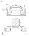
- FIG. 2 is a half-sectional view of the imaging unit 100 according to the first embodiment.
- FIG. 3 is a perspective view of a vibration device 10 according to the first embodiment.
- the X, Y, and Z directions in the figure indicate the horizontal direction, the depth direction, and the height direction of the imaging unit 100, respectively.
- the dashed line shown in FIG. 2 is a part passing through the central axis of the vibration device 10.
- the imaging unit 100 includes a vibration device 10 and a sensor device 20.
- the vibration device 10 has an outermost lens 1, a housing 2, a vibrating body 3, and a piezoelectric element 5.
- the sensor device 20 has an inner lens 4, an imaging element 6, and a bracket 8.
- the sensor device 20 including the image sensor 6 is joined to the vibration device 10 to form the imaging unit 100.
- the sensor device 20 has the inner lens 4, but the inner lens 4 may be provided on the vibration device 10 side.
- the imaging unit 100 only needs to have at least the vibration device 10 that vibrates the outermost lens 1 that transmits light of a predetermined wavelength, and the sensor device 20 including the image sensor 6.
- the imaging element 6 is an image sensor such as a CCD (Charge Coupled Device) or CMOS (Complementary Metal-Oxide-Semiconductor) sensor, and is mounted on a circuit board (not shown).
- the circuit board may be mounted with semiconductor elements such as a general-purpose IC (Integrated Circuit) or ASIC (Application Specific Integrated Circuit) that controls the imaging element 6, as well as semiconductor elements that generate signals to drive the piezoelectric element 5.
- the circuit board is fixed to the bracket 8 at a position where the alignment of the outermost lens 1 and inner lens 4 with the imaging element 6 is adjusted.
- the bracket 8 is made of, for example, aluminum (A5052).
- the outermost lens 1 is a translucent body that transmits light of a predetermined wavelength (e.g., a visible light wavelength, a wavelength that can be imaged by an imaging element, etc.), and is, for example, borosilicate crown glass (BK7), quartz glass, crown glass, flint glass, a convex meniscus lens, etc.
- a predetermined wavelength e.g., a visible light wavelength, a wavelength that can be imaged by an imaging element, etc.
- BK7 borosilicate crown glass
- quartz glass e.g., quartz glass, crown glass, flint glass, a convex meniscus lens, etc.
- the vibration device 10 may use a transparent member such as a protective cover instead of the outermost lens 1.
- the protective cover is made of glass or a resin such as transparent plastic.
- the end of the outermost lens 1 is held by the end of a leaf spring 2a extending from the housing 2. Adhesive is filled between the outermost lens 1 and the retainer 2b at the end of the leaf spring 2a. Furthermore, the vibration device 10 is provided with a vibrating body 3 to vibrate the outermost lens 1 held in the housing 2.
- the housing 2 and the vibrating body 3 are made of, for example, stainless steel (SUS304, SUS420, SUS440), etc.
- the vibrating body 3 is a cylindrical body, and is composed of a connection part 31 (first part) that contacts the outermost lens 1, a vibration part 32 (second part) in which a piezoelectric element 5 is provided, and a support part 33 (third part) that connects the connection part 31 and the vibration part 32.
- the cross-sectional shape of the support part 33 is S-shaped.
- An inner layer lens 4 is arranged inside the cylinder of the vibrating body 3, as shown in FIG. 2.
- connection part 31 has a cylindrical shape that is elongated in the axial direction (Z direction) of the cylindrical body, and the end part is elongated in the radial direction (X and Y directions) of the cylindrical body. Therefore, the end part of the connection part 31 can stably contact the peripheral part of the outermost lens 1. Note that the connection part 31 may be only the part that is elongated in the axial direction (Z direction) of the cylindrical body, or only the part that is elongated in the radial direction (X and Y directions) of the cylindrical body.
- the vibration part 32 is a part that vibrates together with the vibration of the piezoelectric element 5, and has a thickness greater than the thicknesses of the connection part 31 and the support part 33. This makes it easier to transmit the vibration of the piezoelectric element 5 to the outermost lens 1 more efficiently.
- the support part 33 is a part that supports the connection part 31 and transmits the vibration of the vibration part 32 to the connection part 31.
- the connection part 31, the vibration part 32, and the support part 33 may be formed integrally or separately.
- the piezoelectric element 5 is provided on the surface of the vibration part 32 opposite to the side in contact with the outermost lens 1.
- the piezoelectric element 5 is hollow and circular, and vibrates, for example, by polarization in the thickness direction.
- the piezoelectric element 5 is made of lead zirconate titanate piezoelectric ceramics. However, other piezoelectric ceramics such as (K,Na) NbO3 may also be used. Furthermore, a piezoelectric single crystal such as LiTaO3 may also be used.
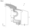
- FIG. 4 is a half cross-sectional view for explaining the vibration of the vibrating device 10 according to the first embodiment.
- the dashed line in Figure 4 is the part that passes through the central axis of the vibrating device 10.
- the vibrating body 3 displaces the outermost lens 1 in the Z direction by elastically deforming the support portion 33 like a spring.
- the vibration of the vibrating body 3 also elastically deforms the leaf spring 2a of the housing 2 that holds the outermost lens 1.
- the vibrating body 3 has a vibration node N in the center of the portion where the cross section of the support portion 33 is S-shaped.
- the vibration of the vibrating body 3 causes the outermost lens 1 to be displaced to its maximum, while the displacement of the vibration node N is small. Note that in FIG. 4, the magnitude of displacement is indicated by the shade of hatching, with darker hatching indicating areas with greater displacement, with the outermost lens 1 having greater displacement.
- protrusions 22 are provided on the bottom surface 21 of the housing 2 to reduce the contact area with the bracket 8.
- the protrusions 22 are provided near the screw holes 23 provided in the four corners of the housing 2.
- the protrusions 22 are also connected to the side surfaces of the housing 2 and provided along the four corners.
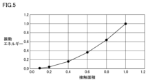
- FIG. 5 is a graph illustrating the relationship between contact area and vibration energy. Note that the horizontal axis in FIG. 5 indicates the contact area between the housing 2 and bracket 8, and the vertical axis indicates the vibration energy leaking to the bracket 8.
- the values of contact area and vibration energy are standardized by setting the contact area to 1 when the entire bottom surface 21 of the housing 2 is in contact with the bracket 8, and the vibration energy at that time to 1. As can be seen from the graph in FIG. 5, vibration energy tends to increase as the contact area increases. Therefore, it can be seen that reducing the contact area between the housing 2 and bracket 8 is effective in reducing vibration leaking from the housing 2 to the bracket 8.
- FIG. 6 is a perspective view of vibration devices 10A and 10B according to a modified example of embodiment 1.
- vibration devices 10A and 10B the same components as those in the vibration device 10 shown in FIG. 3 are given the same reference numerals, and the description thereof will not be repeated.
- protrusions 22a are provided on the bottom surface 21 of the housing 2A to reduce the contact area with the bracket 8.
- the protrusions 22a are provided between the screw holes 23 provided in the four corners of the housing 2A.
- the protrusions 22a are also connected to the side surfaces of the housing 2A and provided on the four sides of the housing 2A.
- protrusions 22b are provided on the bottom surface 21 of the housing 2B to reduce the contact area with the bracket 8.
- the protrusions 22b are provided around the screw holes 23 provided in the four corners of the housing 2B.
- the protrusions 22b are also provided so as to go around the screw holes 23 once.
- the protrusions 22, 22a, 22b are formed integrally with the housings 2, 2A, 2B, but may be formed separately and subsequently joined to the housings. Furthermore, the protrusions may be formed by digging grooves in the bottom surface 21 of the housings 2, 2A, 2B. Although the configuration in which four protrusions 22, 22a, 22b are provided on the bottom surface 21 of the housings 2, 2A, 2B has been described, providing at least three on the bottom surface 21 can ensure alignment between the vibration device 10, 10A, 10B and the sensor device 20.
- the vibration device 10, 10A, 10B is joined to the sensor device 20 by joining the housings 2, 2A, 2B and the bracket 8 via the protrusions 22, 22a, 22b, and fixing with screws from the bracket 8 side (screw mechanism).
- the housings 2, 2A, and 2B may be joined to the bracket 8 via the protrusions 22, 22a, and 22b, and the vibration devices 10, 10A, and 10B may be joined to the sensor device 20 with adhesive.
- Brackets 8A and 8B are provided on the bottom surface 21 of the housings 2, 2A, and 2B, but they may also be provided on the bracket 8 side.
- Figure 7 is a perspective view of brackets 8A and 8B according to a modified example of the first embodiment.
- the bracket 8A has protrusions 82a on the top surface 81 to reduce the contact area with the housing 2.
- the protrusions 82a are provided near the screw holes 83 provided at the four corners of the bracket 8A.
- the protrusions 82a are also provided along the four corners of the bracket 8A.
- bracket 8B has protrusions 82b on the top surface 81 to reduce the contact area with the housing 2.
- Protrusions 82b are provided between screw holes 83 provided at the four corners of bracket 8B.
- Protrusions 82b are also provided on the four sides of bracket 8B.
- the protrusions 82a, 82b are formed integrally with the brackets 8A, 8B, but may be formed separately and subsequently joined to the brackets. Furthermore, the protrusions may be formed by carving grooves in the top surface 81 of the brackets 8A, 8B. Although the configuration in which four protrusions 82a, 82b are provided on the top surface 81 of the brackets 8A, 8B has been described, providing at least three on the top surface 81 can ensure alignment between the vibration device 10 and the sensor device 20. Furthermore, the protrusions may be provided on both the bottom surface of the housing or the top surface of the bracket, rather than on just one of them.
- the housings 2, 2A, and 2B have a rectangular prism shape, but are not limited to this shape.
- Figure 8 is a perspective view of vibration devices 10C and 10D, which have a different shape.
- the vibration devices 10C and 10D the same components as those in the vibration device 10 shown in Figure 3 are given the same reference numerals and will not be described again.
- protrusions 22c are provided on the bottom surface 21 of the cylindrical housing 2C to reduce the contact area with the bracket 8.
- the protrusions 22c are connected to the side surface of the housing 2C and are provided in four places along the circumferential direction of the housing 2C.
- protrusions 22d are provided on the bottom surface 21 of the cylindrical housing 2D to reduce the contact area with the bracket 8.
- the protrusions 22d are provided at four points on the bottom surface 21 of the housing 2D.
- the shape of the housing may be a polygonal prism such as a hexagonal prism or an octagonal prism, in addition to a rectangular prism or a cylindrical shape.
- FIG. 9 is a perspective view of vibration devices 10E to 10G provided with a cushioning material.
- the vibration devices 10E to 10G the same components as those in the vibration device 10 shown in FIG. 3 and the vibration devices 10A and 10B shown in FIG. 6 are designated by the same reference numerals, and the description thereof will not be repeated.
- protrusions 22b are provided on the bottom surface 21 of the housing 2E to reduce the contact area with the bracket 8.
- the protrusions 22b are provided around the screw holes 23 provided at the four corners of the housing 2E.
- the protrusions 22b are also provided so as to go around the screw holes 23.
- the bottom surface 21 of the housing 2E is provided with buffer material 24a on all surfaces where the screw holes 23 and protrusions 22b are not provided.
- the buffer material 24a is, for example, resin, rubber, liquid or gel adhesive, etc.
- the cushioning material 24a is provided on all surfaces that do not have screw holes 23 and protrusions 22b, but cushioning material may be provided where necessary.
- cushioning material 24b is provided on the bottom surface 21 between the screw holes 23 provided in the four corners of the housing 2F.
- the cushioning material 24b is provided on the four sides of the housing 2F.
- cushioning material 24c is provided on the bottom surface 21 around the screw holes 23 provided in the four corners of the housing 2F.
- the cushioning material 24c is provided at the four corners of the housing 2G.
- the cushioning material only needs to be placed in the gap between the housing and the bracket, so it may be provided on the housing side as shown in Figure 9, or on the bracket side.
- FIG. 1 is a cross-sectional view of the imaging unit 100a according to the second embodiment.
- the same components as those in the imaging unit 100 shown in Figures 1 and 2 are denoted by the same reference numerals, and the description thereof will not be repeated.
- the imaging unit 100a includes a vibration device 10H and a sensor device 20C.
- the vibration device 10H has an outermost lens 1, a housing 2H, a vibrating body 3, and a piezoelectric element 5.
- the sensor device 20C has an inner lens 4, an imaging element 6, and a bracket 8C. After adjusting the alignment between the outermost lens 1 and the inner lens 4, the imaging unit 100a is formed by joining the sensor device 20C including the imaging element 6 to the vibration device 10H.
- the sensor device 20C is described as having an inner lens 4, but the inner lens 4 may be provided on the vibration device 10H side.
- the bracket 8C has a fixing portion 84 that protrudes from the surface that is joined to the vibration device 10H.
- the fixing portion 84 is formed to surround the side of the housing 2H, and forms a recess when the bottom side of the housing 2H is a protrusion.
- the vibration device 10H and the sensor device 20C are fixed by a fitting mechanism that fits the protrusion on the bottom side of the housing 2H into the recess formed by the fixing portion 84.
- the inside of the fixing part 84 and the side of the housing 2H may be directly in contact with each other, but in the imaging unit 100a, as shown in FIG. 10, an O-ring 26 is provided in a groove 25 provided on the side of the housing 2H, and the inside of the fixing part 84 and the side of the housing 2H are in contact with each other via the O-ring 26.
- the O-ring 26 is made of a material such as silicone or nitrile rubber (NBR). Instead of joining the inside of the fixing part 84 and the side of the housing 2H via the O-ring 26, they may be joined using a metal leaf spring, a sponge, a rubber sheet, an adhesive, or the like.
- a protrusion 22h is provided on the bottom surface of housing 2H at the joint between the bottom surface of housing 2H and the top surface of bracket 8C.
- the shape of protrusion 22h may be any shape as long as it is the shape of the protrusion described in embodiment 1.
- a protrusion may be provided on the top surface side of bracket 8C.
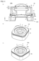
- FIG. 11 is a schematic diagram of an imaging unit 100b relating to the first variation of the second embodiment.
- FIG. 11(a) is a cross-sectional view of the imaging unit 100b
- FIG. 11(b) is a perspective view of a vibration device 10I
- FIG. 11(c) is a perspective view of another vibration device 10J.
- the same components as those in the imaging unit 100 shown in FIGS. 1 and 2 and the imaging unit 100a shown in FIG. 10 are designated by the same reference numerals and will not be described again.
- the housing 2H and the bracket 8C are joined via the protrusion 22h, so a gap is created between the housing 2H and the bracket 8C, and there is an air layer in the gap.
- a buffer material 24d is provided in the gap between the housing 2I and the bracket 8C.
- the buffer material 24d is, for example, resin, rubber, or a liquid or gel adhesive.
- protrusions 22 are provided on the bottom surface of the housing 2I.
- the protrusions 22 are provided at the four corners of the housing 2I.
- cushioning material 24d is provided on all surfaces that do not have protrusions 22.
- a protrusion 22 is provided on the bottom surface of the housing 2I, but the vibration device may have no protrusion on the bottom surface of the housing.
- the vibration device 10Ia as shown in FIG. 11(c), no protrusion is provided on the bottom surface of the housing 2Ia, and cushioning material 24e is provided on the entire bottom surface of the housing 2Ia.
- the cushioning material 24e is, for example, resin, rubber, or liquid or gel adhesive.
- FIG. 12 is a cross-sectional view of an imaging unit 100c according to the second variation of the second embodiment.
- the same components as those in the imaging unit 100 shown in FIGS. 1 and 2 and the imaging unit 100a shown in FIG. 10 are given the same reference numerals and will not be described repeatedly.
- the vibration device 10J no protrusions or cushioning material are provided on the bottom surface of the housing 2J.
- the housing 2J and the bracket 8C are simply joined via the fixing part 84, and there is an air layer between the bottom surface of the housing 2J and the top surface of the bracket 8C.
- FIG. 13 is a perspective view of an imaging unit 100d according to the third embodiment.
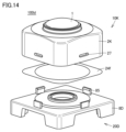
- Fig. 14 is an exploded perspective view of the imaging unit 100d according to the third embodiment.
- the same components as those of the imaging unit 100 shown in Figs. 1 and 2 are denoted by the same reference numerals, and the description thereof will not be repeated.
- the imaging unit 100d includes a vibration device 10K and a sensor device 20D.
- the vibration device 10K has an outermost lens 1, a housing 2K, a vibrating body 3 (not shown), and a piezoelectric element 5 (not shown).
- the sensor device 20D has an inner lens 4 (not shown), an imaging element 6 (not shown), and a bracket 8D. After adjusting the alignment between the outermost lens 1 and the inner lens 4, the imaging unit 100d is formed by joining the sensor device 20D including the imaging element 6 to the vibration device 10K.
- the sensor device 20D is described as having an inner lens 4, but the inner lens 4 may be provided on the side of the vibration device 10K.
- the bracket 8D has a claw portion 85 protruding from the surface that is joined to the vibration device 10K.
- claw portions 85 are provided corresponding to the side surfaces of the housing 2K, but multiple claw portions may be provided.
- the side surface of the housing 2K is provided with a recess 27 for engaging with the claw portions 85.
- the claw portions 85 of the bracket 8D engage with the recesses 27 of the housing 2K to join the vibration device 10K and the sensor device 20D.
- the claw portions 85 of the bracket 8D and the recesses 27 of the housing 2K form a snap-fit mechanism, which is a mechanical joining mechanism of the imaging unit 100d.
- the snap-fit mechanism is provided on the side surface of the housing 2K, but may also be provided on the inside of the housing 2K.
- a cushioning material 24f is provided in the gap between the housing 2K and the bracket 8D.
- the cushioning material 24f is, for example, resin, rubber, or liquid or gel adhesive.
- the imaging unit 100d may have a protrusion on the bottom surface of the housing 2K or a protrusion on the top surface of the bracket 8D as described in the first embodiment.
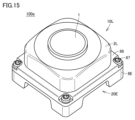
- FIG. 15 is a perspective view of the imaging unit 100e according to the fourth embodiment.
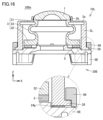
- Fig. 16 is a cross-sectional view of the imaging unit 100e according to the fourth embodiment.
- the same components as those of the imaging unit 100 shown in Figs. 1 and 2 are denoted by the same reference numerals, and the description thereof will not be repeated.
- the imaging unit 100e includes a vibration device 10L and a sensor device 20E.
- the vibration device 10L has an outermost lens 1, a housing 2L, a vibrating body 3, and a piezoelectric element 5.
- the sensor device 20E has an inner lens 4 (not shown), an imaging element 6 (not shown), and a bracket 8E. After adjusting the alignment between the outermost lens 1 and the inner lens 4, the imaging unit 100e is formed by joining the sensor device 20E including the imaging element 6 to the vibration device 10L.
- the sensor device 20E is described as having an inner lens 4, but the inner lens 4 may be provided on the side of the vibration device 10L.
- the bracket 8E has a fixing portion 86 for holding the housing 2L of the vibration device 10L against the sensor device 20E, and a screw 87 for joining the fixing portion 86 to the bracket 8E.
- the housing 2L has four flanges 28 near the bottom surface that correspond to the side surfaces of the housing 2L.
- the fixing portion 86 holds the housing 2L against the sensor device 20E by sandwiching the flanges 28 between the fixing portion 86 and the top surface of the bracket 8E.
- the fixing portion 86 of the bracket 8D and the flanges 28 of the housing 2L form a holding mechanism, and are the mechanical joining mechanism of the imaging unit 100e.
- the joining of the fixing portion 86 and the bracket 8E is not limited to the screw 87, and may be performed by other joining methods such as adhesive. Although it has been described that four flanges 28 are provided corresponding to the sides of the housing 2L, it is sufficient to provide multiple flanges, and they may be provided so as to go around the entire side of the housing 2L.
- a cushioning material 24g is provided in the gap between the housing 2L and the bracket 8E.
- the cushioning material 24g is, for example, resin, rubber, or liquid or gel adhesive.
- the imaging unit 100e may have a protrusion on the bottom surface of the housing 2L or a protrusion on the top surface of the bracket 8E as described in the first embodiment.
- a crimping portion is provided on the bracket, and the vibration device and the sensor device are joined by bending the bracket so that a part of the housing of the vibration device and the crimping portion engage with each other.
- the crimping portion of the bracket is the crimping mechanism, which is the mechanical joining mechanism of the imaging unit.
- the bracket in the above embodiment is described as being made of, for example, aluminum (A5052). However, this is not limited to the above, and the bracket may use a material in the portion where it joins the housing that attenuates vibration more than other portions (for example, engineering plastic, resin such as rubber, or metal such as Kovar or stainless steel (SUS430)).
- the cross-sectional shape of the support portion 33 is described as being S-shaped, but the cross-sectional shape of the support portion is not limited to an S-shape as long as the shape does not cause stress concentration in the vibrating body.
- the cross-sectional shape of the support portion 33 may be, for example, a shape formed by connecting multiple S-shapes, or a curved shape that is half an S-shape.
- the imaging unit in the above-described embodiment may include a camera, LiDAR, radar, etc. Also, multiple imaging units may be arranged side by side.
- the imaging unit according to the above-mentioned embodiment is not limited to an imaging unit installed in a vehicle, but can be similarly applied to any imaging unit that includes an optical device and an imaging element arranged so that the light-transmitting body is in the field of view, and that requires the removal of foreign objects from the light-transmitting body.
- An imaging unit includes: An imaging unit including a vibration device that vibrates a light-transmitting body that transmits light of a predetermined wavelength, and a sensor device including an imaging element, a plurality of protrusions are provided on at least one of a housing of the vibration device and a bracket of the sensor device; The housing and the bracket are joined via a plurality of protrusions so that the light-transmitting body is included in the field of view of the imaging element disposed on the bracket.
- the imaging unit according to the present disclosure does not reduce the performance of vibrating the translucent body because the housing and bracket are joined via multiple protrusions.
- the imaging unit described in (1) further includes a cushioning material sandwiched in the gap between the housing and the bracket.
- Another imaging unit includes: An imaging unit including a vibration device that vibrates a light-transmitting body that transmits light of a predetermined wavelength, and a sensor device including an imaging element, The housing of the vibration device and the bracket of the sensor device are joined via a cushioning material so that the light-transmitting body is included in the field of view of the imaging element arranged on the bracket of the sensor device.
- the imaging unit according to the present disclosure does not reduce the performance of vibrating the translucent body because the housing and bracket are joined via a cushioning material.
- the housing and the bracket are joined with an adhesive or a mechanical joining mechanism.
- the joining mechanism has any one of a screw mechanism, a fitting mechanism, a snap-fit mechanism, a holding mechanism, and a crimping mechanism.
- the snap-fit mechanism is provided on the side of the housing.
- the bracket uses a material in the portion where it joins with the housing that attenuates vibration more than other portions.
- the vibration device A transparent body; A housing for holding a light-transmitting body; A vibrator that vibrates a light-transmitting body held in a housing; A piezoelectric element is provided on the vibrating body and vibrates the vibrating body,
- the vibrating body is a cylindrical body having a first portion at one end that contacts the light-transmitting body or the housing, and a second portion at the other end where the piezoelectric element is provided.
- the vibrating body has a third portion that connects the first portion and the second portion and has a curved cross-sectional shape.
- the cross-sectional shape of the third portion is S-shaped.
- the sensor device is An imaging element; A bracket for fixing the imaging element; and an optical component fixed to the bracket and having an optical axis aligned with the imaging element.
Landscapes
- Physics & Mathematics (AREA)
- Engineering & Computer Science (AREA)
- Multimedia (AREA)
- Signal Processing (AREA)
- General Physics & Mathematics (AREA)
- Optics & Photonics (AREA)
- Electromagnetism (AREA)
- Studio Devices (AREA)
- Vibration Prevention Devices (AREA)
- Lens Barrels (AREA)
Abstract
Description
図1は、実施の形態1に係る撮像ユニット100の概略図である。図2は、実施の形態1に係る撮像ユニット100の半断面図である。図3は、実施の形態1に係る振動デバイス10の斜視図である。なお、図中のX,Y,Z方向は、それぞれ、撮像ユニット100の横方向、奥行き方向、高さ方向を示す。図2に示す破線は、振動デバイス10の中心軸を通る部分である。撮像ユニット100は、振動デバイス10、センサデバイス20を含む。振動デバイス10は、最外層レンズ1、筐体2、振動体3、圧電素子5を有している。センサデバイス20は、内層レンズ4、撮像素子6、ブラケット8を有している。
実施の形態1に係る撮像ユニット100では、図1~図3に示すように、筐体2とブラケット8とを複数の突起部22を介して接合し、ブラケット8側からネジで振動デバイス10とセンサデバイス20とを固定すると説明した。実施の形態2では、嵌め合い機構で振動デバイスとセンサデバイスとを固定する撮像ユニットについて説明する。図10は、実施の形態2に係る撮像ユニット100aの断面図である。撮像ユニット100aにおいて、図1~図2に示す撮像ユニット100と同様の構成については同じ符号を付して、その説明は繰り返さない。
実施の形態1に係る撮像ユニット100では、図1~図3に示すように、筐体2とブラケット8とを複数の突起部22を介して接合し、ブラケット8側からネジで振動デバイス10とセンサデバイス20とを固定すると説明した。実施の形態3では、スナップフィット機構で振動デバイスとセンサデバイスとを固定する撮像ユニットについて説明する。図13は、実施の形態3に係る撮像ユニット100dの斜視図である。図14は、実施の形態3に係る撮像ユニット100dの分解斜視図である。撮像ユニット100dにおいて、図1~図2に示す撮像ユニット100と同様の構成については同じ符号を付して、その説明は繰り返さない。
実施の形態1に係る撮像ユニット100では、図1~図3に示すように、筐体2とブラケット8とを複数の突起部22を介して接合し、ブラケット8側からネジで振動デバイス10とセンサデバイス20とを固定すると説明した。実施の形態4では、押さえ機構で振動デバイスとセンサデバイスとを固定する撮像ユニットについて説明する。図15は、実施の形態4に係る撮像ユニット100eの斜視図である。図16は、実施の形態4に係る撮像ユニット100eの断面図である。撮像ユニット100eにおいて、図1~図2に示す撮像ユニット100と同様の構成については同じ符号を付して、その説明は繰り返さない。
前述の実施の形態に係る撮像ユニットでは、振動デバイスとセンサデバイスとの接合について様々な接合方法を説明したが、これらの接合方法以外の方法を用いて接合してもよい。たとえば、撮像ユニットでは、ブラケットにカシメ部を設け、振動デバイスの筐体の一部と当該カシメ部とが係合するように折り曲げることで振動デバイスとセンサデバイスとを接合する。このブラケットのカシメ部がカシメ機構で、撮像ユニットの機械的な接合機構である。
(1) 本開示に係る撮像ユニットは、
所定の波長の光を透過する透光体を加振する振動デバイスと、撮像素子を含むセンサデバイスと、を備える撮像ユニットであって、
振動デバイスの筐体、またはセンサデバイスのブラケットの少なくとも一方に複数の突起部を設け、
ブラケットに配置した撮像素子の視野方向に透光体が含まれるように、筐体とブラケットとを複数の突起部を介して接合する。
所定の波長の光を透過する透光体を加振する振動デバイスと、撮像素子を含むセンサデバイスと、を備える撮像ユニットであって、
センサデバイスのブラケットに配置した撮像素子の視野方向に透光体が含まれるように、振動デバイスの筐体とブラケットとを緩衝材を介して接合する。
振動デバイスは、
透光体と、
透光体を保持する筐体と、
筐体に保持された透光体を加振する振動体と、
振動体に設けられ、振動体を振動させる圧電素子と、を備え、
振動体は、筒状体であって、一方の端に透光体または筐体と接する第1部分を有し、他方の端に圧電素子を設ける第2部分を有する。
センサデバイスは、
撮像素子と、
撮像素子を固定するブラケットと、
ブラケットに固定され、撮像素子に対して光軸のアライメントが取れた光学部品と、を備える。
Claims (11)
- 所定の波長の光を透過する透光体を加振する振動デバイスと、撮像素子を含むセンサデバイスと、を備える撮像ユニットであって、
前記振動デバイスの筐体、または前記センサデバイスのブラケットの少なくとも一方に複数の突起部を設け、
前記ブラケットに配置した前記撮像素子の視野方向に前記透光体が含まれるように、前記筐体と前記ブラケットとを前記複数の突起部を介して接合する、撮像ユニット。 - 前記筐体と前記ブラケットとの隙間に挟まれる緩衝材をさらに含む、請求項1に記載の撮像ユニット。
- 所定の波長の光を透過する透光体を加振する振動デバイスと、撮像素子を含むセンサデバイスと、を備える撮像ユニットであって、
前記センサデバイスのブラケットに配置した前記撮像素子の視野方向に前記透光体が含まれるように、前記振動デバイスの筐体と前記ブラケットとを緩衝材を介して接合する、撮像ユニット。 - 前記筐体と前記ブラケットとを、接着剤、または機械的な接合機構で接合する、請求項1~請求項3のいずれか1項に記載の撮像ユニット。
- 前記接合機構は、ネジ機構、嵌め合い機構、スナップフィット機構、押さえ機構、およびカシメ機構のうちのいずれかの機構を有する、請求項4に記載の撮像ユニット。
- 前記スナップフィット機構は、前記筐体の側面側に設けられている、請求項5に記載の撮像ユニット。
- 前記ブラケットは、前記筐体と接合する部分に、他の部分より振動を減衰させる材料を用いる、請求項1~請求項6のいずれか1項に記載の撮像ユニット。
- 前記振動デバイスは、
前記透光体と、
前記透光体を保持する筐体と、
前記筐体に保持された前記透光体を加振する振動体と、
前記振動体に設けられ、前記振動体を振動させる圧電素子と、を備え、
前記振動体は、筒状体であって、一方の端に前記透光体または前記筐体と接する第1部分を有し、他方の端に前記圧電素子を設ける第2部分を有する、請求項1~請求項7のいずれか1項に記載の撮像ユニット。 - 前記振動体は、前記第1部分と前記第2部分とを繋ぐ第3部分の断面形状が曲線形状である、請求項8に記載の撮像ユニット。
- 前記振動体は、前記第3部分の断面形状がS字形状である、請求項9に記載の撮像ユニット。
- 前記センサデバイスは、
前記撮像素子と、
前記撮像素子を固定する前記ブラケットと、
前記ブラケットに固定され、前記撮像素子に対して光軸のアライメントが取れた光学部品と、を備える、請求項1~請求項10のいずれか1項に記載の撮像ユニット。
Priority Applications (3)
| Application Number | Priority Date | Filing Date | Title |
|---|---|---|---|
| CN202480007222.8A CN120513415A (zh) | 2023-03-17 | 2024-02-08 | 摄像单元 |
| DE112024000294.3T DE112024000294T5 (de) | 2023-03-17 | 2024-02-08 | Bilderzeugungseinheit |
| US19/259,289 US20250328008A1 (en) | 2023-03-17 | 2025-07-03 | Imaging unit |
Applications Claiming Priority (2)
| Application Number | Priority Date | Filing Date | Title |
|---|---|---|---|
| JP2023-043361 | 2023-03-17 | ||
| JP2023043361A JP2024132549A (ja) | 2023-03-17 | 2023-03-17 | 撮像ユニット |
Related Child Applications (1)
| Application Number | Title | Priority Date | Filing Date |
|---|---|---|---|
| US19/259,289 Continuation US20250328008A1 (en) | 2023-03-17 | 2025-07-03 | Imaging unit |
Publications (1)
| Publication Number | Publication Date |
|---|---|
| WO2024195343A1 true WO2024195343A1 (ja) | 2024-09-26 |
Family
ID=92841319
Family Applications (1)
| Application Number | Title | Priority Date | Filing Date |
|---|---|---|---|
| PCT/JP2024/004288 Ceased WO2024195343A1 (ja) | 2023-03-17 | 2024-02-08 | 撮像ユニット |
Country Status (5)
| Country | Link |
|---|---|
| US (1) | US20250328008A1 (ja) |
| JP (1) | JP2024132549A (ja) |
| CN (1) | CN120513415A (ja) |
| DE (1) | DE112024000294T5 (ja) |
| WO (1) | WO2024195343A1 (ja) |
Families Citing this family (1)
| Publication number | Priority date | Publication date | Assignee | Title |
|---|---|---|---|---|
| JP2024147053A (ja) * | 2023-04-03 | 2024-10-16 | ニデックインスツルメンツ株式会社 | レンズユニット、およびレンズ調芯方法 |
Citations (6)
| Publication number | Priority date | Publication date | Assignee | Title |
|---|---|---|---|---|
| WO2019130629A1 (ja) * | 2017-12-27 | 2019-07-04 | 株式会社村田製作所 | 振動装置及び光学検出装置 |
| WO2019225042A1 (ja) * | 2018-05-22 | 2019-11-28 | 株式会社村田製作所 | 振動装置及び光学検出装置 |
| WO2020003572A1 (ja) * | 2018-06-28 | 2020-01-02 | 株式会社村田製作所 | 振動装置及び光学検出装置 |
| JP2020181079A (ja) * | 2019-04-25 | 2020-11-05 | 株式会社村田製作所 | 振動装置及び光学検出装置 |
| WO2021210208A1 (ja) * | 2020-04-17 | 2021-10-21 | 株式会社村田製作所 | 振動装置 |
| WO2021229852A1 (ja) * | 2020-05-15 | 2021-11-18 | 株式会社村田製作所 | 振動装置 |
-
2023
- 2023-03-17 JP JP2023043361A patent/JP2024132549A/ja active Pending
-
2024
- 2024-02-08 DE DE112024000294.3T patent/DE112024000294T5/de active Pending
- 2024-02-08 WO PCT/JP2024/004288 patent/WO2024195343A1/ja not_active Ceased
- 2024-02-08 CN CN202480007222.8A patent/CN120513415A/zh active Pending
-
2025
- 2025-07-03 US US19/259,289 patent/US20250328008A1/en active Pending
Patent Citations (6)
| Publication number | Priority date | Publication date | Assignee | Title |
|---|---|---|---|---|
| WO2019130629A1 (ja) * | 2017-12-27 | 2019-07-04 | 株式会社村田製作所 | 振動装置及び光学検出装置 |
| WO2019225042A1 (ja) * | 2018-05-22 | 2019-11-28 | 株式会社村田製作所 | 振動装置及び光学検出装置 |
| WO2020003572A1 (ja) * | 2018-06-28 | 2020-01-02 | 株式会社村田製作所 | 振動装置及び光学検出装置 |
| JP2020181079A (ja) * | 2019-04-25 | 2020-11-05 | 株式会社村田製作所 | 振動装置及び光学検出装置 |
| WO2021210208A1 (ja) * | 2020-04-17 | 2021-10-21 | 株式会社村田製作所 | 振動装置 |
| WO2021229852A1 (ja) * | 2020-05-15 | 2021-11-18 | 株式会社村田製作所 | 振動装置 |
Also Published As
| Publication number | Publication date |
|---|---|
| US20250328008A1 (en) | 2025-10-23 |
| DE112024000294T5 (de) | 2025-11-27 |
| JP2024132549A (ja) | 2024-10-01 |
| CN120513415A (zh) | 2025-08-19 |
Similar Documents
| Publication | Publication Date | Title |
|---|---|---|
| EP3731014B1 (en) | Vibration device and optical detection device | |
| CN108474998B (zh) | 振动装置及其驱动方法、以及摄像头 | |
| JP7099633B2 (ja) | 振動装置 | |
| JP6819844B1 (ja) | 振動装置、および振動装置を備える撮像ユニット | |
| WO2023127197A1 (ja) | 振動装置及び撮像装置 | |
| US20250328008A1 (en) | Imaging unit | |
| WO2021038942A1 (ja) | 振動装置及び光学検出装置 | |
| JP7666662B2 (ja) | 振動装置および撮像装置 | |
| JP7758173B2 (ja) | 光学装置、および光学装置を備える撮像ユニット | |
| JP7655455B2 (ja) | 光学装置、および光学装置を備える撮像ユニット | |
| WO2024202260A1 (ja) | 光学装置、および光学装置を備える撮像ユニット | |
| WO2025150230A1 (ja) | 撮像装置 | |
| JP7859482B2 (ja) | 光学装置、および光学装置を備える撮像ユニット | |
| JP7776020B2 (ja) | 光学装置、および光学装置を備える撮像ユニット | |
| WO2023162330A1 (ja) | 光学装置、および光学装置を備える撮像ユニット | |
| JP7663134B2 (ja) | 光学モジュールおよび光学装置 | |
| WO2025032897A1 (ja) | 振動装置、および撮像装置 | |
| WO2025027965A1 (ja) | 振動装置、および撮像装置 | |
| WO2020137262A1 (ja) | 振動装置及び光学検出装置 | |
| JP2009130615A (ja) | 撮像装置および光学機器 | |
| WO2026062949A1 (ja) | 振動装置、および撮像装置 | |
| JP5245870B2 (ja) | 光学装置および撮影装置 | |
| WO2025248827A1 (ja) | 振動装置、および撮像装置 | |
| WO2022113701A1 (ja) | 振動装置 | |
| JP2012233970A (ja) | 撮像装置の製造方法及び撮像装置用位置調整治具 |
Legal Events
| Date | Code | Title | Description |
|---|---|---|---|
| 121 | Ep: the epo has been informed by wipo that ep was designated in this application |
Ref document number: 24774489 Country of ref document: EP Kind code of ref document: A1 |
|
| WWE | Wipo information: entry into national phase |
Ref document number: 202480007222.8 Country of ref document: CN |
|
| WWE | Wipo information: entry into national phase |
Ref document number: 112024000294 Country of ref document: DE |
|
| WWP | Wipo information: published in national office |
Ref document number: 202480007222.8 Country of ref document: CN |
|
| WWP | Wipo information: published in national office |
Ref document number: 112024000294 Country of ref document: DE |
|
| 122 | Ep: pct application non-entry in european phase |
Ref document number: 24774489 Country of ref document: EP Kind code of ref document: A1 |