WO2024194928A1 - エアロゾル生成システム、及び制御方法 - Google Patents
エアロゾル生成システム、及び制御方法 Download PDFInfo
- Publication number
- WO2024194928A1 WO2024194928A1 PCT/JP2023/010607 JP2023010607W WO2024194928A1 WO 2024194928 A1 WO2024194928 A1 WO 2024194928A1 JP 2023010607 W JP2023010607 W JP 2023010607W WO 2024194928 A1 WO2024194928 A1 WO 2024194928A1
- Authority
- WO
- WIPO (PCT)
- Prior art keywords
- heating
- unit
- heating unit
- control unit
- resistance
- Prior art date
- Legal status (The legal status is an assumption and is not a legal conclusion. Google has not performed a legal analysis and makes no representation as to the accuracy of the status listed.)
- Ceased
Links
Images


Classifications
-
- A—HUMAN NECESSITIES
- A24—TOBACCO; CIGARS; CIGARETTES; SIMULATED SMOKING DEVICES; SMOKERS' REQUISITES
- A24F—SMOKERS' REQUISITES; MATCH BOXES; SIMULATED SMOKING DEVICES
- A24F40/00—Electrically operated smoking devices; Component parts thereof; Manufacture thereof; Maintenance or testing thereof; Charging means specially adapted therefor
- A24F40/50—Control or monitoring
- A24F40/53—Monitoring, e.g. fault detection
-
- A—HUMAN NECESSITIES
- A24—TOBACCO; CIGARS; CIGARETTES; SIMULATED SMOKING DEVICES; SMOKERS' REQUISITES
- A24F—SMOKERS' REQUISITES; MATCH BOXES; SIMULATED SMOKING DEVICES
- A24F40/00—Electrically operated smoking devices; Component parts thereof; Manufacture thereof; Maintenance or testing thereof; Charging means specially adapted therefor
- A24F40/40—Constructional details, e.g. connection of cartridges and battery parts
- A24F40/46—Shape or structure of electric heating means
-
- A—HUMAN NECESSITIES
- A24—TOBACCO; CIGARS; CIGARETTES; SIMULATED SMOKING DEVICES; SMOKERS' REQUISITES
- A24F—SMOKERS' REQUISITES; MATCH BOXES; SIMULATED SMOKING DEVICES
- A24F40/00—Electrically operated smoking devices; Component parts thereof; Manufacture thereof; Maintenance or testing thereof; Charging means specially adapted therefor
- A24F40/20—Devices using solid inhalable precursors
-
- A—HUMAN NECESSITIES
- A24—TOBACCO; CIGARS; CIGARETTES; SIMULATED SMOKING DEVICES; SMOKERS' REQUISITES
- A24F—SMOKERS' REQUISITES; MATCH BOXES; SIMULATED SMOKING DEVICES
- A24F40/00—Electrically operated smoking devices; Component parts thereof; Manufacture thereof; Maintenance or testing thereof; Charging means specially adapted therefor
- A24F40/50—Control or monitoring
- A24F40/51—Arrangement of sensors
-
- A—HUMAN NECESSITIES
- A24—TOBACCO; CIGARS; CIGARETTES; SIMULATED SMOKING DEVICES; SMOKERS' REQUISITES
- A24F—SMOKERS' REQUISITES; MATCH BOXES; SIMULATED SMOKING DEVICES
- A24F40/00—Electrically operated smoking devices; Component parts thereof; Manufacture thereof; Maintenance or testing thereof; Charging means specially adapted therefor
- A24F40/50—Control or monitoring
- A24F40/57—Temperature control
Definitions
- This disclosure relates to an aerosol generation system and a control method.
- inhalation devices such as electronic cigarettes and nebulizers
- inhalation devices generate aerosol imparted with flavor components using a substrate that includes an aerosol source for generating aerosol and a flavor source for imparting flavor components to the generated aerosol.
- Users can taste the flavor by inhaling the aerosol imparted with flavor components generated by the inhalation device.
- the action of a user inhaling an aerosol is hereinafter also referred to as a puff or a puffing action.
- Patent Document 1 discloses a technology that detects the insertion of a substrate into the suction device based on a change in capacitance detected by a capacitance sensor mounted on the suction device.
- the present disclosure has been made in consideration of the above problems, and the purpose of the present disclosure is to provide a mechanism that enables further miniaturization of the suction device.
- an aerosol generation system includes a power supply unit that accumulates and supplies power, a storage unit that stores a substrate containing an aerosol source, a heating unit that uses power supplied from the power supply unit to heat the substrate stored in the storage unit, and a control unit that controls the power supply to the heating unit, and the control unit determines the state of the storage unit based on parameters corresponding to the elapsed time since the heating unit started heating to generate an aerosol and the temperature of the heating unit.
- the control unit may control the operation of the heating unit based on the result of determining the state of the storage unit.
- the control unit may determine the state of the storage unit based on the elapsed time when the parameter satisfies a first condition.
- the control unit may continue heating by the heating unit when the elapsed time when the parameter satisfies the first condition is equal to or greater than a first threshold, and may stop heating by the heating unit when the elapsed time when the parameter satisfies the first condition is less than the first threshold.
- the control unit may set the first threshold value based on the parameters when the heating unit starts heating.
- the control unit may set the first threshold value based on the parameters when the heating unit is in a specified temperature environment.
- the control unit may be configured to maintain a duty ratio of the voltage applied to the heating unit at a predetermined value during a period from when the heating unit starts heating to generate an aerosol until the parameter satisfies the second condition, and to change the duty ratio of the voltage applied to the heating unit when the parameter satisfies the second condition, so that the first condition is satisfied before the second condition is satisfied.
- the control unit may determine the state of the storage unit based on the parameters when the elapsed time reaches a second threshold value.
- the control unit may continue heating by the heating unit if the parameter satisfies a third condition when the elapsed time reaches the second threshold, and may stop heating by the heating unit if the parameter does not satisfy the third condition when the elapsed time reaches the second threshold.
- the control unit may set the second threshold value based on the parameters when the heating unit starts heating.
- the control unit may maintain a duty ratio of the voltage applied to the heating unit at a predetermined value during a period from when the heating unit starts heating to generate an aerosol until the parameter satisfies a second condition, and change the duty ratio of the voltage applied to the heating unit when the parameter satisfies the second condition, and the second threshold may be set such that the elapsed time reaches the second threshold before the parameter satisfies the second condition.
- the control unit may determine the state of the storage unit based on the time series transition of a parameter corresponding to the temperature of the heating unit obtained by repeatedly applying a group of detection pulses including one first detection pulse to the heating unit, and may start heating to generate an aerosol by the heating unit based on the determination result.
- the control unit may switch between whether or not to execute a process for determining the state of the storage unit based on the elapsed time and the parameters, based on the parameters when the heating unit starts heating.
- the aerosol generating system may further include the substrate.
- a control method executed by a computer that controls an aerosol generation system the aerosol generation system having a power supply unit that accumulates and supplies power, a storage unit that stores a substrate containing an aerosol source, and a heating unit that uses the power supplied from the power supply unit to heat the substrate stored in the storage unit, the control method including controlling the power supply to the heating unit, and the control of the power supply to the heating unit including determining the state of the storage unit based on a parameter corresponding to the elapsed time since the heating unit started heating to generate an aerosol and the temperature of the heating unit.
- the present disclosure provides a mechanism that allows for further miniaturization of the suction device.
- FIG. 1 is a schematic diagram showing a configuration example of a suction device
- 10A and 10B are diagrams for explaining a first process executed by a suction device according to an embodiment of the present disclosure.
- 5A to 5C are diagrams for explaining a first process executed by the suction device according to the present embodiment.
- 1 is a graph showing a schematic example of a heating profile.
- 11 is a diagram for explaining power supply control based on a heating profile.
- FIG. 11A to 11C are diagrams for explaining experimental results regarding the suction device according to the present embodiment.
- 5 is a flowchart showing an example of a flow of a process executed by the suction device according to the present embodiment.
- 10A to 10C are diagrams for explaining a second process executed by the suction device according to the present embodiment.
- FIG. 11 is a diagram for explaining adjustment of a determination criterion performed by the suction device according to the present embodiment.
- FIG. 11A to 11C are diagrams for explaining experimental results regarding the suction device according to the present embodiment.
- 10 is a flowchart showing an example of a flow of a second process executed by the suction device according to the embodiment.
- elements having substantially the same functional configuration may be distinguished by assigning an index containing different letters or numbers after the same reference numeral.
- multiple elements having substantially the same functional configuration may be distinguished as devices 1A, 1B, and 1C as necessary.
- only the same reference numeral may be assigned.
- devices 1A, 1B, and 1C they may be referred to simply as device 1.
- the inhalation device is a device that generates a substance to be inhaled by a user.
- the substance generated by the inhalation device is described as an aerosol.
- the substance generated by the inhalation device may be a gas.
- FIG. 1 is a schematic diagram showing an example of the configuration of a suction device.
- the suction device 100 includes a power supply unit 111, a sensor unit 112, a notification unit 113, a memory unit 114, a communication unit 115, a control unit 116, a heating unit 121, a storage unit 140, and a heat insulating unit 144.
- the power supply unit 111 stores power.
- the power supply unit 111 supplies power to each component of the suction device 100 under the control of the control unit 116.
- the power supply unit 111 may be configured, for example, by a rechargeable battery such as a lithium ion secondary battery.
- the sensor unit 112 acquires various information related to the suction device 100.
- the sensor unit 112 is configured with a pressure sensor such as a condenser microphone, a flow rate sensor, or a temperature sensor, and acquires values associated with suction by the user.
- the sensor unit 112 is configured with an input device such as a button or switch that accepts information input from the user.
- the notification unit 113 notifies the user of information.
- the notification unit 113 is composed of, for example, a light-emitting device that emits light, a display device that displays an image, a sound output device that outputs sound, or a vibration device that vibrates.
- the storage unit 114 stores various information for the operation of the suction device 100.
- the storage unit 114 is configured, for example, from a non-volatile storage medium such as a flash memory.
- the communication unit 115 is a communication interface capable of performing communication conforming to any wired or wireless communication standard.
- Such communication standards may include, for example, standards using Wi-Fi (registered trademark), Bluetooth (registered trademark), BLE (Bluetooth Low Energy (registered trademark)), NFC (Near Field Communication), or LPWA (Low Power Wide Area).
- the control unit 116 functions as an arithmetic processing unit and a control unit, and controls the overall operation of the suction device 100 in accordance with various programs.
- the control unit 116 is realized by an electronic circuit such as a CPU (Central Processing Unit) or a microprocessor.
- the storage section 140 has an internal space 141 and holds the stick-shaped substrate 150 while storing a part of the stick-shaped substrate 150 in the internal space 141.
- the storage section 140 has an opening 142 that connects the internal space 141 to the outside, and stores the stick-shaped substrate 150 inserted into the internal space 141 through the opening 142.
- the storage section 140 is a cylindrical body with the opening 142 and the bottom 143 as the bottom surface, and defines a columnar internal space 141.
- An air flow path that supplies air to the internal space 141 is connected to the storage section 140.
- An air inlet hole which is an air inlet to the air flow path, is arranged, for example, on the side of the suction device 100.
- An air outlet hole which is an air outlet from the air flow path to the internal space 141, is arranged, for example, on the bottom 143.
- the stick-type substrate 150 includes a substrate portion 151 and a mouthpiece portion 152.
- the substrate portion 151 includes an aerosol source.
- the aerosol source includes a flavor component derived from tobacco or non-tobacco.
- the aerosol source may include a medicine.
- the aerosol source may be a liquid such as polyhydric alcohols such as glycerin and propylene glycol, and water, which include a flavor component derived from tobacco or non-tobacco, or may be a solid which includes a flavor component derived from tobacco or non-tobacco.
- the stick-type substrate 150 When the stick-type substrate 150 is held in the storage portion 140, at least a portion of the substrate portion 151 is stored in the internal space 141, and at least a portion of the mouthpiece portion 152 protrudes from the opening 142.
- the suction mouth portion 152 protruding from the opening 142 in their mouth and inhales air flows into the internal space 141 via an air flow path (not shown) and reaches the user's mouth together with the aerosol generated from the base portion 151.
- the heating unit 121 generates aerosol by heating the aerosol source and atomizing the aerosol source.
- the heating unit 121 is configured in a film shape and is arranged to cover the outer periphery of the storage unit 140.
- the heating unit 121 generates heat, the substrate unit 151 of the stick-shaped substrate 150 is heated from the outer periphery, and an aerosol is generated.
- the heating unit 121 generates heat when power is supplied from the power supply unit 111.
- power may be supplied when the sensor unit 112 detects that the user has started inhaling and/or that specific information has been input. Power supply may be stopped when the sensor unit 112 detects that the user has stopped inhaling and/or that specific information has been input.
- the insulating section 144 prevents heat transfer from the heating section 121 to other components.
- the insulating section 144 is made of a vacuum insulating material or an aerogel insulating material.
- the configuration of the suction device 100 is not limited to the above, and various configurations such as those exemplified below are possible.
- the heating unit 121 may be configured in a blade shape and disposed so as to protrude from the bottom 143 of the storage unit 140 into the internal space 141.
- the blade-shaped heating unit 121 is inserted into the substrate 151 of the stick-shaped substrate 150 and heats the substrate 151 of the stick-shaped substrate 150 from the inside.
- the heating unit 121 may be disposed so as to cover the bottom 143 of the storage unit 140.
- the heating unit 121 may be configured as a combination of two or more of a first heating unit that covers the outer periphery of the storage unit 140, a blade-shaped second heating unit, and a third heating unit that covers the bottom 143 of the storage unit 140.
- the storage unit 140 may include an opening/closing mechanism such as a hinge that opens and closes a portion of the outer shell that forms the internal space 141. The storage unit 140 may then open and close the outer shell to accommodate the stick-shaped substrate 150 inserted into the internal space 141 while clamping it.
- the heating unit 121 may be provided at the clamping location in the storage unit 140, and may heat the stick-shaped substrate 150 while pressing it.
- the heating unit 121 uses power supplied from the power supply unit 111 to heat the stick-shaped substrate 150 (more specifically, the aerosol source contained in the stick-shaped substrate 150) contained in the storage unit 140, thereby generating an aerosol.
- the control unit 116 then controls the power supply to the heating unit 121.
- the suction device 100 is an example of an aerosol generation system that generates an aerosol.
- the combination of the suction device 100 and the stick-shaped substrate 150 may be regarded as an aerosol generation system.
- the control unit 116 determines the state of the accommodation unit 140 based on a parameter corresponding to the temperature of the heating unit 121.
- the parameter corresponding to the temperature of the heating unit 121 is assumed to be the electrical resistance (hereinafter also simply referred to as resistance) of the heating unit 121 (more precisely, the heating resistor constituting the heating unit 121).
- the control unit 116 obtains the resistance of the heating unit 121 by applying a voltage to the heating unit 121.
- the resistance of the heating unit 121 increases as the temperature of the heating unit 121 increases, and the resistance of the heating unit 121 decreases as the temperature of the heating unit 121 decreases. That is, in the following description, the resistance and the temperature may be interchangeable.
- the control unit 116 executes a first process.
- the first process includes acquiring the resistance of the heating unit 121 and judging the state of the storage unit 140 based on the acquired resistance of the heating unit 121. In particular, in the first process, the control unit 116 judges whether or not the stick-shaped substrate 150 has been inserted into the storage unit 140.
- the control section 116 ends the first process and executes the second process.
- the second process includes heating the stick-shaped substrate 150 based on a heating profile.
- the heating profile is control information for generating an aerosol.
- the suction device 100 can generate an aerosol by heating the stick-shaped substrate 150 based on the heating profile. The heating profile will be described in detail later.
- the stick-shaped substrate 150 may be erroneously determined that the stick-shaped substrate 150 is inserted into the storage section 140 even though the stick-shaped substrate 150 is not inserted into the storage section 140.
- Such an erroneous determination may occur when an item other than the stick-shaped substrate 150, such as a cleaning swab, is inserted into the storage section 140, or when outside air is blown into the storage section 140. This is because the resistance of the heating section 121 may change in these cases, just as it does when the stick-shaped substrate 150 is inserted into the storage section 140.
- the control unit 116 therefore acquires the resistance of the heating unit 121 during heating based on the heating profile, and judges the state of the storage unit 140 based on the acquired resistance of the heating unit 121. In particular, the control unit 116 judges whether or not the judgment in the first process that the stick-shaped substrate 150 has been inserted into the storage unit 140 was an erroneous judgment.
- control unit 116 determines that the stick-shaped substrate 150 is inserted in the storage unit 140, i.e., if it determines that the determination in the first process is correct, it continues heating the stick-shaped substrate 150 based on the heating profile. On the other hand, if the control unit 116 determines that the stick-shaped substrate 150 is not inserted in the storage unit 140, i.e., if it determines that the determination in the first process is incorrect, it stops heating the stick-shaped substrate 150 based on the heating profile.
- the heating section 121 for heating the stick-shaped substrate 150 can be used to detect the insertion of the stick-shaped substrate 150. In other words, there is no need to install another sensor such as a capacitance sensor to detect the insertion of the stick-shaped substrate 150. This allows the suction device 100 to be further miniaturized.
- the heating section 121 may increase in temperature.
- the first process may be considered as a process for heating the stick-shaped substrate 150.
- heating refers to heating based on the heating profile in the second process.
- FIGS. 2 and 3 are diagrams for explaining the first processing performed by the suction device 100 according to this embodiment.
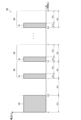
- a graph 30 shown in FIG. 2 shows an example of a time series transition of a voltage applied to the heating unit 121 in the first processing.
- the vertical axis of the graph 30 is voltage in volts.
- the horizontal axis of the graph 30 is time in seconds.
- a graph 35 shown in FIG. 3 shows an example of a time series transition of the resistance of the heating unit 121 when the voltage shown in FIG. 2 is applied.
- the vertical axis of the graph 35 is resistance in ohms.
- the horizontal axis of the graph 35 is time in seconds.
- the graph 35 illustrates a case where the stick-type substrate 150 is inserted into the storage unit 140 at the timing indicated by the arrow 39, i.e., 5 seconds after the start of the first processing.
- the control unit 116 repeatedly applies a group of detection pulses 34 including one first detection pulse 31 to the heating unit 121.
- the pulse here is a wave having a predetermined voltage.
- the first detection pulse 31 is a pulse for increasing the temperature of the heating unit 121 while acquiring the resistance of the heating unit 121.
- the period during which one group of detection pulses 34 is applied is also referred to as a detection cycle below.
- the period during which the first detection pulse 31 is applied in the detection cycle is also referred to as a temperature rise period.
- the period during which the first detection pulse 31 is not applied in the detection cycle is also referred to as a temperature fall period.
- the duration of the detection cycle is 0.5 seconds
- the first 0.1 seconds of the detection cycle is the temperature rise period
- the remaining 0.4 seconds is the temperature fall period.
- the resistance of the heating section 121 fluctuates up and down.
- the resistance of the heating section 121 in the process in which the application of the detection pulse group 34 is repeated, the resistance of the heating section 121 repeatedly rises and falls, and then gradually rises.
- the voltage and width of the first detection pulse 31 are adjusted so that the resistance of the heating section 121 gradually rises or is maintained at a constant value in the process in which the application of the detection pulse group 34 is repeated.
- the control unit 116 determines the state of the storage unit 140 based on the time series transition of the resistance of the heating unit 121 obtained by repeatedly applying the detection pulse group 34 to the heating unit 121. In detail, the control unit 116 determines that the stick-shaped substrate 150 has been inserted into the storage unit 140 when the time series transition of the resistance of the heating unit 121 satisfies a predetermined condition. On the other hand, the control unit 116 determines that the stick-shaped substrate 150 has not been inserted into the storage unit 140 when the time series transition of the resistance of the heating unit 121 does not satisfy the predetermined condition.
- the time series transition of the resistance of the heating section 121 during the period when the detection pulse group 34 is applied to the heating section 121 differs between the case where the stick-shaped substrate 150 is inserted in the storage section 140 and the case where it is not.
- the stick-shaped substrate 150 is not inserted in the storage section 140 during the period from the start of the first process to the elapse of 5 seconds.
- the resistance at the start of the application of the first detection pulse 31 is located on line 37
- the resistance at the end of the application of the first detection pulse 31 is located on line 38.
- the stick-shaped substrate 150 is inserted in the storage section 140 during the period after 5 seconds have elapsed from the start of the first process.
- the control unit 116 determines that the stick-shaped substrate 150 has been inserted into the storage unit 140. With this configuration, it becomes possible to determine whether or not the stick-shaped substrate 150 has been inserted into the storage unit 140 with a simple configuration.
- the first process may include first applying a third detection pulse 33 to the heating unit 121.
- the third detection pulse 33 is a pulse for increasing the temperature of the heating unit 121 while acquiring the resistance of the heating unit 121.
- the duration of the third detection pulse 33 is longer than the duration of the first detection pulse 31.
- the duration of the first detection pulse 31 is 0.1 seconds
- the duration of the third detection pulse 33 is 0.5 seconds.
- the detection pulse group 34 may include one or more second detection pulses in addition to the one first detection pulse 31.
- the second detection pulse is a pulse for acquiring the resistance of the heating section 121.
- the duration of the second detection pulse is shorter than the duration of the first detection pulse 31.
- the resistance of the heating section 121 obtained by the second detection pulse can be used to determine the state of the storage section 140.
- the state of the storage section 140 can be determined based on a larger number of samples, making it possible to suppress a decrease in the accuracy of determining the state of the storage section 140 due to, for example, the influence of disturbances.
- the control unit 116 may start the first process when a predetermined user action is detected as a trigger.
- the predetermined user action may be any user action that is assumed to result in the stick-type substrate 150 being inserted into the storage unit 140 immediately after the predetermined user action is performed.
- One example of the predetermined user action is opening the lid that opens and closes the opening 142.
- Another example of the predetermined user action is lifting the suction device 100.
- Another example of the predetermined user action is canceling the charging of the suction device 100.
- the presence or absence of these predetermined user actions may be detected by a sensor provided on the lid, a motion sensor, or the like. With this configuration, the first process may be performed only at the timing when the stick-type substrate 150 may be inserted. This makes it possible to reduce power consumption.
- the control unit 116 ends the first process if the time series change in the resistance of the heating unit 121 does not satisfy a predetermined condition until a predetermined time has elapsed since the start of the first process. In other words, the control unit 116 stops the first process if it does not determine that the stick-shaped substrate 150 has been inserted into the storage unit 140 until a predetermined time has elapsed since the start of the first process.
- the predetermined time may be set, for example, according to the time that is normally assumed to be required from the time the user performs a predetermined user operation that triggers the start of the first process to the time the stick-shaped substrate 150 is inserted. In the example shown in FIG. 2, the predetermined time is 10 seconds, and the detection cycle is repeated a maximum of 18 times. With this configuration, it is possible to suppress power consumption within a range that does not deteriorate usability.
- control unit 116 starts the second process when it is determined in the first process that the time series change in the resistance of the heating unit 121 satisfies a predetermined condition.
- control unit 116 starts the second process when it is determined in the first process that the stick-shaped substrate 150 has been inserted into the storage unit 140.
- control unit 116 controls the operation of the heating unit 121 based on the heating profile, and determines the state of the accommodation unit 140. These processing will be described in order below.
- the control unit 116 controls the operation of the heating unit 121 based on a heating profile.
- the control of the operation of the heating unit 121 is realized by controlling the power supply from the power source unit 111 to the heating unit 121.
- the heating unit 121 heats the stick-shaped substrate 150 using the power supplied from the power source unit 111.
- the heating profile is control information for controlling the temperature at which the aerosol source is heated.
- the heating profile specifies the target value of a parameter corresponding to the temperature at which the aerosol source is heated.
- An example of the temperature at which the aerosol source is heated is the temperature of the heating unit 121.
- An example of the target value of a parameter corresponding to the temperature at which the aerosol source is heated is the target value of the temperature of the heating unit 121 (hereinafter also referred to as the target temperature).
- the temperature of the heating unit 121 may be controlled to change according to the elapsed time from the start of heating. In that case, the heating profile includes information that specifies the time series progression of the target temperature.
- the heating profile may include parameters that specify the method of supplying power to the heating unit 121 (hereinafter also referred to as the power supply parameters).
- the power supply parameters include, for example, the voltage applied to the heating unit 121, ON/OFF of the power supply to the heating unit 121, or the feedback control method to be adopted. Turning the power supply to the heating unit 121 on/off may be considered as turning the heating unit 121 on/off.
- the control unit 116 controls the operation of the heating unit 121 so that the temperature of the heating unit 121 (hereinafter also referred to as the actual temperature) changes in the same manner as the target temperature defined in the heating profile.
- the heating profile is typically designed to optimize the flavor experienced by the user when the user inhales the aerosol generated from the stick-shaped substrate 150. Therefore, by controlling the operation of the heating unit 121 based on the heating profile, the flavor experienced by the user can be optimized.
- the temperature control of the heating unit 121 can be realized, for example, by known feedback control.
- the feedback control may be, for example, PID control (Proportional-Integral-Differential Controller).
- the control unit 116 may supply power from the power supply unit 111 to the heating unit 121 in the form of pulses by pulse width modulation (PWM) or pulse frequency modulation (PFM).
- PWM pulse width modulation
- PFM pulse frequency modulation
- the control unit 116 can control the temperature of the heating unit 121 by adjusting the duty ratio of the power pulse in the feedback control.
- the control unit 116 may perform simple on/off control in the feedback control.
- control unit 116 may perform heating by the heating unit 121 until the actual temperature reaches the target temperature, interrupt heating by the heating unit 121 when the actual temperature reaches the target temperature, and resume heating by the heating unit 121 when the actual temperature becomes lower than the target temperature.
- the temperature of the heating section 121 can be quantified, for example, by measuring or estimating the electrical resistance value of the heating section 121 (more precisely, the heating resistor that constitutes the heating section 121). This is because the electrical resistance value of the heating resistor changes depending on the temperature.
- the electrical resistance value of the heating resistor can be estimated, for example, by measuring the amount of voltage drop in the heating resistor.
- the amount of voltage drop in the heating resistor can be measured by a voltage sensor that measures the potential difference applied to the heating resistor.
- the temperature of the heating section 121 can be measured by a temperature sensor such as a thermistor installed near the heating section 121.
- a heating session is a period during which power supply to the heating unit 121 is controlled based on a heating profile.
- the start of a heating session is the timing when heating based on the heating profile starts.
- the end of a heating session is the timing when a sufficient amount of aerosol is no longer generated.
- a heating session includes a pre-heating period in the first half and a puffable period in the second half.
- the puffable period is a period during which a sufficient amount of aerosol is expected to be generated.
- the pre-heating period is the period from the start of heating to the start of the puffable period. Heating performed during the pre-heating period is also referred to as pre-heating.
- the notification unit 113 may notify the user of information indicating the timing at which preheating will end. For example, the notification unit 113 may notify the user of information predicting the end of preheating before the end of preheating, or may notify the user of information indicating that preheating has ended at the timing at which preheating has ended.
- the notification to the user may be performed, for example, by lighting an LED or vibrating. The user may refer to such a notification and begin puffing immediately after preheating has ended.
- the notification unit 113 may notify the user of information indicating the timing when the puffing period will end. For example, the notification unit 113 may notify the user of information predicting the end of the puffing period before the end of the puffing period, or may notify the user of information indicating that the puffing period has ended at the timing when the puffing period has ended.
- the notification to the user may be performed, for example, by lighting an LED or vibrating. The user may refer to such a notification and continue puffing until the puffing period ends.
- FIG. 4 is a graph that shows a schematic example of a heating profile.
- the horizontal axis of graph 20 is time.
- the vertical axis of graph 20 is temperature.
- Line 21 shows the time series progression of the target temperature.
- a heating session may include an initial heating period, an intermediate temperature drop period, and a re-heating period, in that order.
- the initial heating period is a period in which the temperature of the heating unit 121 rises rapidly after the start of heating and is maintained at a high temperature.
- the intermediate temperature drop period is a period in which the temperature of the heating unit 121 drops after the initial heating period.
- the re-heating period is a period in which the temperature of the heating unit 121 rises again after the intermediate temperature drop period.
- the target temperature rises rapidly to around 300°C during the initial heating period, then drops to around 230°C during the intermediate temperature drop period, and then rises stepwise to around 260°C during the re-heating period.
- power supply to the heating unit 121 may be interrupted and heating may be turned off.
- the period from the start of heating to the middle of the initial temperature rise period is the pre-heating period, and the period from the middle of the initial temperature rise period to the end of the re-heating period is the puffable period.
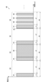
- FIG. 5 is a diagram for explaining power supply control based on a heating profile.
- Graph 40 shown in FIG. 5 shows an example of the time series transition of the voltage applied to the heating section 121 during power supply control based on a heating profile.
- the vertical axis of graph 40 is voltage in volts.
- the horizontal axis of graph 40 is time in milliseconds.
- the control unit 116 repeatedly applies a heating pulse group 44 including a measurement pulse 41 to the heating unit 121.
- the measurement pulse 41 is a pulse applied to measure the resistance of the heating unit 121.
- the heating pulse group 44 may include one or more heating pulses 42.
- the heating pulse 42 is a pulse applied to increase the temperature of the heating unit 121.
- the period during which one heating pulse group 44 is applied is also referred to as a heating cycle below.
- the period during which the measurement pulses 41 are applied during the heating cycle is also referred to as a measurement period.
- the period during which the measurement pulses 41 are not applied during the heating cycle is also referred to as a non-measurement period.
- the heating pulses 42 may be applied.
- the duration of the heating cycle is 50 milliseconds, with the first 3 milliseconds of the heating cycle being the measurement period and the remaining 47 milliseconds being the non-measurement period.
- the control unit 116 controls the configuration of the heating pulse 42 during the non-measurement period.
- the configuration here refers to whether or not the heating pulse 42 is applied, and the duration of the heating pulse 42.
- the duration of the heating pulse 42 can be set to any time equal to or less than 47 milliseconds.
- the number and start timing of the heating pulses 42 during the non-measurement period can also be set arbitrarily.
- control unit 116 acquires the resistance of the heating unit 121 when the measurement pulse 41 is applied during the measurement period. Then, based on the resistance of the heating unit 121 acquired during the measurement period and the heating profile, the control unit 116 controls the configuration of the heating pulse 42 during the non-measurement period that belongs to the same heating cycle as the measurement period. In so doing, the control unit 116 controls the duty ratio of the heating pulse 42 during the non-measurement period based on the temperature of the heating unit 121 calculated from the resistance of the heating unit 121 and the target temperature specified in the heating profile.
- the above-mentioned heating pulse group 44 is applied to the heating unit 121 during the initial heating period and the reheating period of the heating session.
- the heating pulse group 44 does not have to be applied to the heating unit 121 during the intermediate temperature drop period of the heating session.
- whether or not the temperature of the heating unit 121 has dropped to the target temperature during the intermediate temperature drop period may be determined by a separately provided temperature sensor such as a thermistor, or may be simply determined based on the elapsed time since the supply of power to the heating unit 121 was stopped.
- the control unit 116 determines the state of the storage unit 140 based on the time series transition of the resistance of the heating unit 121 obtained by repeatedly applying the heating pulse group 44 to the heating unit 121. In detail, when the time series transition of the resistance of the heating unit 121 satisfies a predetermined condition, the control unit 116 determines that the stick-shaped substrate 150 has been inserted into the storage unit 140. On the other hand, when the time series transition of the resistance of the heating unit 121 does not satisfy the predetermined condition, the control unit 116 determines that the stick-shaped substrate 150 has not been inserted into the storage unit 140.
- the time series transition of the resistance of the heating unit 121 during the period when the heating pulse group 44 is applied to the heating unit 121 differs depending on whether or not the stick-shaped substrate 150 is inserted in the storage unit 140.
- the resistance (i.e., temperature) of the heating unit 121 rises rapidly compared to when the stick-shaped substrate 150 is inserted in the storage unit 140. Therefore, for example, the control unit 116 determines that the stick-shaped substrate 150 is inserted in the storage unit 140 when the time series transition of the resistance of the heating unit 121 falls within the range of the time series transition of the resistance of the heating unit 121 expected when the stick-shaped substrate 150 is inserted. With this configuration, it becomes possible to determine whether or not the stick-shaped substrate 150 is inserted in the storage unit 140 with a simple configuration.
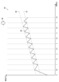
- FIG. 6 is a diagram for explaining the experimental results regarding the suction device 100 according to this embodiment.
- Graph 50 shown in FIG. 6 shows the time series change in the resistance of the heating section 121 when the suction device 100 executes the first process and the second process.
- the vertical axis of graph 50 is resistance in ohms.
- the horizontal axis of graph 50 is time in seconds.
- the resistance of the heating section 121 measured at each time point is plotted on graph 50, and consecutive plots in time are connected by lines.
- Graph 50 shows the time series change in the resistance of the heating section 121 when the stick-shaped substrate 150 is inserted at the timing indicated by arrow 59, i.e., 4.5 seconds after the start of the first process.
- the resistance of the heating section 121 repeatedly rises and falls, gradually increasing until the stick-shaped substrate 150 is inserted. Then, immediately after the stick-shaped substrate 150 is inserted, the resistance of the heating section 121 drops from plot 51A to plot 51B, and from plot 52A to plot 52B. Note that plots 51A and 51B correspond to the resistance of the heating section 121 at the start of application of the first detection pulse 31. Plots 52A and 52B correspond to the resistance of the heating section 121 at the end of application of the first detection pulse 31. Based on this drop in the resistance of the heating section 121, the control section 116 determines that the stick-shaped substrate 150 has been inserted into the storage section 140. Therefore, the first process ends and the second process begins, and the resistance of the heating section 121 rises rapidly.
- FIG. 7 is a flowchart showing an example of the process flow executed by the suction device 100 according to this embodiment.
- the control unit 116 determines whether a specific user operation has been detected (step S102). For example, the control unit 116 determines whether a user operation to open a cover that opens and closes the opening 142, a user operation to lift the suction device 100, or a user operation to cancel charging of the suction device 100 has been detected by the sensor unit 112.
- step S102 If it is determined that the specified user operation has not been detected (step S102: NO), the control unit 116 waits until the specified user operation is detected.
- step S104 the control unit 116 starts the first process (step S104). For example, the control unit 116 first applies the third detection pulse 33 to the heating unit 121, and then repeatedly applies the detection pulse group 34 to the heating unit 121.
- control unit 116 determines whether or not the stick-shaped substrate 150 has been inserted into the storage unit 140 (step S106). For example, the control unit 116 determines whether or not the stick-shaped substrate 150 has been inserted into the storage unit 140 based on whether or not the time series transition of the resistance of the heating unit 121 obtained by repeatedly applying the detection pulse group 34 to the heating unit 121 satisfies a predetermined condition.
- step S106 If it is determined that the stick-shaped substrate 150 has been inserted into the storage unit 140 (step S106: YES), the control unit 116 ends the first process and starts the second process (step S108). For example, the storage unit 140 repeatedly applies the heating pulse group 44 to the heating unit 121 based on the heating profile.
- step S106 determines whether a predetermined time has elapsed since the start of the first process (step S110). For example, the control unit 116 determines whether 10 seconds have elapsed since the start of the first process.
- step S110 NO
- the process returns to step S106.
- step S110 YES
- the control unit 116 ends the first process (step S112). Then, the process ends.
- control unit 116 determines whether or not the determination result in the first process is correct (step S114). For example, the control unit 116 determines whether or not the stick-shaped substrate 150 has been inserted into the storage unit 140 based on whether or not the time series transition of the resistance of the heating unit 121 obtained by repeatedly applying the heating pulse group 44 to the heating unit 121 satisfies a predetermined condition.
- step S114 If the result of the first process is determined to be correct, that is, if it is determined that the stick-shaped substrate 150 is inserted into the storage section 140 (step S114: YES), the control section 116 continues heating based on the heating profile (step S116). When heating based on the heating profile ends, the process ends.
- step S114 if it is determined that the result of the first process is erroneous, that is, if it is determined that the stick-shaped substrate 150 is not inserted in the storage section 140 (step S114: NO), the control section 116 ends the heating based on the heating profile (step S118). Then, the process ends.
- the notification unit 113 may appropriately notify information indicating the progress of the above-mentioned processing. For example, the notification unit 113 may notify that a first processing has been started, the determination result of the first processing, that a second processing has been started, and the determination result of the second processing.
- Criteria in the second process The following is a detailed description of the criteria used in the second process to determine the state of the container 140.
- the criteria are set by the control unit 116.
- the control unit 116 determines the state of the storage unit 140 based on the time elapsed since the heating unit 121 started heating to generate an aerosol and parameters corresponding to the temperature of the heating unit 121. That is, in the second process, the control unit 116 determines whether or not the stick-shaped substrate 150 is inserted into the storage unit 140 based on the time elapsed since the heating based on the heating profile started and the resistance of the heating unit 121. In detail, the control unit 116 determines that the stick-shaped substrate 150 is inserted into the storage unit 140 when the time elapsed since the heating based on the heating profile started and the resistance of the heating unit 121 satisfy a predetermined condition.
- the control unit 116 determines that the stick-shaped substrate 150 is not inserted into the storage unit 140 when the time elapsed since the heating based on the heating profile started and the resistance of the heating unit 121 do not satisfy a predetermined condition. With this configuration, it is possible to determine whether or not the stick-shaped substrate 150 is inserted into the storage unit 140 with a simple configuration. In the following, the time elapsed since the start of heating based on the heating profile is also referred to as the heating time.
- the control unit 116 controls the operation of the heating unit 121 based on the determination result of the state of the storage unit 140. In detail, when the control unit 116 determines that the stick-shaped substrate 150 is inserted in the storage unit 140, it continues heating the stick-shaped substrate 150 based on the heating profile. On the other hand, when the control unit 116 determines that the stick-shaped substrate 150 is not inserted in the storage unit 140, it stops heating the stick-shaped substrate 150 based on the heating profile. This configuration makes it possible to improve usability in that it is not necessary to give a separate instruction to continue/stop heating.
- the control unit 116 may determine the state of the accommodation unit 140 based on the heating time when the resistance of the heating unit 121 satisfies a first condition. Such a criterion is also referred to as the first criterion. According to the first criterion, it is possible to easily determine the state of the accommodation unit 140 based on the length of the heating time. The first criterion will be described in detail below with reference to FIG. 8.
- FIG. 8 is a diagram for explaining the second process executed by the suction device 100 according to this embodiment.
- a graph 60 shown in FIG. 8 shows an example of the time series change in the resistance of the heating section 121 after heating based on the heating profile is started.
- the vertical axis of the graph 60 is the resistance in ohms.
- the horizontal axis of the graph 60 is the time, more specifically, the heating time in seconds.
- Line 61 shows the time series change in the resistance of the heating unit 121 when heating is started with the stick-shaped substrate 150 inserted in the storage unit 140.
- Line 62 shows the time series change in the resistance of the heating unit 121 when heating is started with nothing inserted in the storage unit 140.
- Line 63 shows the time series change in the resistance of the heating unit 121 when heating is started with a dry cotton swab inserted in the storage unit 140.
- Line 64 shows the time series change in the resistance of the heating unit 121 when heating is started with a wet cotton swab inserted in the storage unit 140.
- the control unit 116 may determine that the stick-shaped substrate 150 is inserted into the storage unit 140 if the heating time when the resistance of the heating unit 121 satisfies the first condition is equal to or greater than the first threshold. The control unit 116 may then continue heating by the heating unit 121. On the other hand, the control unit 116 may determine that the stick-shaped substrate 150 is not inserted into the storage unit 140 if the heating time when the resistance of the heating unit 121 satisfies the first condition is less than the first threshold. The control unit 116 may then stop heating by the heating unit 121.
- the first condition may be that the resistance of the heating unit 121 reaches 99.5% of the resistance corresponding to the highest target temperature.
- the highest target temperature here may be the highest target temperature among the target temperatures specified in the heating profile, and in particular, may be the highest target temperature in the pre-heating period. It is desirable that the first threshold value be set according to the heating time required for the resistance of the heating unit 121 to satisfy the first condition when the stick-shaped substrate 150 is inserted in the storage unit 140.
- the first condition may be that the resistance of the heating unit 121 reaches 1.5 ⁇ .
- the first threshold value may be set to 3.5 seconds.
- the heating time required for the resistance of the heating unit 121 to reach 1.5 ⁇ is about 4.2 seconds. Therefore, according to the first judgment criterion, it is possible to judge that the stick-shaped substrate 150 is inserted into the storage unit 140.
- the heating time required for the resistance of the heating unit 121 to reach 1.5 ⁇ is less than 3 seconds.
- the first judgment criterion it is possible to judge that the stick-shaped substrate 150 is not inserted into the storage unit 140. In this way, according to the first judgment criterion, it is possible to appropriately judge whether or not the stick-shaped substrate 150 is inserted into the storage unit 140.
- these numerical values for the first condition and the first threshold are merely examples, and any other numerical values may be used.
- control unit 116 maintains the duty ratio of the voltage applied to the heating unit 121 at a predetermined value during the period from when the heating unit 121 starts heating to generate an aerosol until the resistance of the heating unit 121 satisfies the second condition.
- the control unit 116 maintains the duty ratio of the voltage applied to the heating unit 121 at 100% during the period from when the heating unit 121 starts heating based on the heating profile until the resistance of the heating unit 121 reaches 99.8% of the resistance corresponding to the highest target temperature. This is because there is a large temperature difference between the actual temperature of the heating unit 121 and the target temperature (e.g., 300°C) immediately after the start of heating. This makes it possible to minimize the length of the pre-heating period.
- target temperature e.g. 300°C
- the control unit 116 changes the duty ratio of the voltage applied to the heating unit 121 when the resistance of the heating unit 121 satisfies the second condition. For example, when the resistance of the heating unit 121 reaches 99.8% of the resistance corresponding to the highest target temperature, the control unit 116 reduces the duty ratio of the voltage applied to the heating unit 121 to less than 100%. This makes it possible to prevent the temperature of the heating unit 121 from exceeding the highest target temperature.
- the first condition is desirably set so that it is satisfied before the second condition is satisfied. With this configuration, it is determined whether or not the first condition is satisfied during the period in which the duty ratio is fixed at 100%. Therefore, the influence of changes in the duty ratio can be eliminated from the determination of whether or not the first condition is satisfied, which makes it possible to improve the accuracy of the state determination of the storage section 140.
- the second condition can be determined from a coefficient in PID control.
- control unit 116 may maintain the duty ratio of the voltage applied to the heating unit 121 at a predetermined value during the period from when the heating unit 121 starts heating to generate the aerosol until the resistance of the heating unit 121 satisfies the first condition. With this configuration, it is possible to improve the accuracy of determining the state of the storage unit 140, as described above.
- the control unit 116 may determine the state of the accommodation unit 140 based on the resistance of the heating unit 121 when the heating time reaches a second threshold. Such a criterion is also referred to as the second criterion. According to the second criterion, it is possible to easily determine the state of the accommodation unit 140 based on the resistance of the heating unit 121.
- the second criterion is a reverse of the relationship between the heating time and the resistance of the heating unit 121 in the first criterion. The second criterion will be described in detail below with reference to FIG. 8 again.
- the control unit 116 may determine that the stick-shaped substrate 150 is inserted into the storage unit 140 if the resistance of the heating unit 121 when the heating time reaches the second threshold satisfies the third condition. The control unit 116 may then continue heating by the heating unit 121. On the other hand, the control unit 116 may determine that the stick-shaped substrate 150 is not inserted into the storage unit 140 if the resistance of the heating unit 121 when the heating time reaches the second threshold does not satisfy the third condition. The control unit 116 then stops heating by the heating unit 121.
- the third condition may be that the resistance of the heating unit 121 is less than 99.5% of the resistance corresponding to the highest target temperature.
- the highest target temperature here is the highest target temperature among the target temperatures specified in the heating profile, and may in particular be the highest target temperature in the pre-heating period. It is desirable that the second threshold be set based on the heating time required for the resistance of the heating unit 121 to satisfy the third condition when the stick-shaped substrate 150 is inserted in the storage unit 140.
- the third condition may be that the resistance of the heating section 121 is less than 1.5 ⁇ .
- the second threshold may be set to 3.5 seconds. Referring to line 61, when the stick-shaped substrate 150 is inserted in the storage section 140, the resistance of the heating section 121 at the heating time of 3.5 seconds is less than 1.5 ⁇ . Therefore, according to the second judgment criterion, it is possible to judge that the stick-shaped substrate 150 is inserted in the storage section 140. On the other hand, referring to lines 62 to 64, when the stick-shaped substrate 150 is not inserted in the storage section 140, the resistance of the heating section 121 at the heating time of 3.5 seconds exceeds 1.5 ⁇ .
- the second judgment criterion it is possible to judge that the stick-shaped substrate 150 is not inserted in the storage section 140. In this way, according to the second judgment criterion, it is possible to appropriately judge whether or not the stick-shaped substrate 150 is inserted in the storage section 140.
- these numerical values for the third condition and the second threshold are merely examples, and any other numerical values may be used.
- the second threshold value so that the heating time reaches the second threshold value before the resistance of the heating unit 121 satisfies the second condition.
- control unit 116 may maintain the duty ratio of the voltage applied to the heating unit 121 at a predetermined value for the period until the heating time reaches the second threshold value. With this configuration, it is possible to improve the accuracy of determining the state of the storage unit 140, as described above.
- non-continuous heating i.e., heating that is started when a long time has passed since the previous heating ended and the heating unit 121 is sufficiently cooled
- first heating continuous heating
- second heating continuous heating
- judgment criteria described above with reference to Figure 8 are the judgment criteria adopted during the first heating.
- the control unit 116 adjusts the judgment criteria based on the resistance of the heating unit 121 at the start of heating based on the heating profile, that is, based on whether the heating that has started is the first heating or the second heating. With this configuration, it is possible to suppress a decrease in the accuracy of judging the state of the storage unit 140 during the second heating.
- the control unit 116 may adjust the first criterion based on the resistance of the heating unit 121 at the start of heating based on the heating profile. As an example, the control unit 116 may set the first threshold value based on the resistance of the heating unit 121 at the start of heating based on the heating profile. In detail, the control unit 116 may set the first threshold value lower as the resistance of the heating unit 121 at the start of heating based on the heating profile is higher. A method of setting the first threshold value will be described in detail with reference to FIG. 9.
- FIG. 9 is a diagram for explaining the adjustment of the judgment criteria performed by the suction device 100 according to this embodiment.
- Graph 70 shown in FIG. 9 shows an example of the time series change in the resistance of the heating section 121 when a second heating based on a heating profile is started 30 seconds after the previous heating is finished.
- the vertical axis of graph 70 is resistance in ohms.
- the horizontal axis of graph 70 is time, more specifically, heating time in seconds.
- Line 71 shows the time series change in the resistance of the heating section 121 when the second heating is started with the stick-shaped substrate 150 inserted in the storage section 140.
- Line 72 shows the time series change in the resistance of the heating section 121 when the second heating is started with the stick-shaped substrate 150 not inserted in the storage section 140.
- the first condition may be that the resistance of the heating unit 121 reaches 1.5 ⁇ , as in the example shown in FIG. 8.
- the heating time required for the resistance of the heating unit 121 to reach 1.5 ⁇ is approximately 1.6 seconds.
- the heating time required for the resistance of the heating unit 121 to reach 1.5 ⁇ is approximately 0.6 seconds. In other words, in the example shown in FIG. 9, whether the stick-shaped substrate 150 is inserted into the storage unit 140 or not, the heating time required for the resistance of the heating unit 121 to reach 1.5 ⁇ is less than 3.5 seconds.
- the control unit 116 may change the first threshold to a value based on the resistance of the heating unit 121 at the start of heating based on the heating profile. For example, the control unit 117 may set the first threshold to 1 second. In this case, the control unit 116 can determine that the stick-shaped substrate 150 is inserted into the storage unit 140 for the wire 71 because the heating time required for the resistance of the heating unit 121 to reach 1.5 ⁇ exceeds 1 second. On the other hand, the control unit 116 can determine that the stick-shaped substrate 150 is not inserted into the storage unit 140 for the wire 72 because the heating time required for the resistance of the heating unit 121 to reach 1.5 ⁇ is less than 1 second. In this way, with this configuration, it becomes possible to appropriately determine whether or not the stick-shaped substrate 150 is inserted into the storage unit 140 even during the second heating.
- the control unit 116 may adjust the second judgment criterion based on the resistance of the heating unit 121 at the start of heating based on the heating profile.
- the control unit 116 may set the second threshold value based on the resistance of the heating unit 121 at the start of heating based on the heating profile.
- the control unit 116 may set the second threshold value lower as the resistance of the heating unit 121 at the start of heating based on the heating profile is higher. A method of setting the second threshold value will be described in detail with reference to FIG. 9 again.
- the third condition may be that the resistance of the heating unit 121 is less than 1.5 ⁇ , as in the example shown in FIG. 8.
- the resistance of the heating unit 121 exceeds 1.5 ⁇ when the heating time is 3.5 seconds.
- the resistance of the heating unit 121 exceeds 1.5 ⁇ when the heating time is 3.5 seconds. Therefore, in the example shown in FIG. 9, as in the example shown in FIG. 8, if 3.5 seconds is used as the second threshold, it will be erroneously determined that the stick-shaped substrate 150 is not inserted in the storage unit 140, regardless of whether the stick-shaped substrate 150 is inserted in the storage unit 140 or not.
- the control unit 116 may change the second threshold to a value based on the resistance of the heating unit 121 at the start of heating based on the heating profile. For example, the control unit 117 may set the second threshold to 1 second. In this case, the control unit 116 can determine that the stick-shaped substrate 150 is inserted into the storage unit 140 for the line 71 because the resistance of the heating unit 121 at the time when the heating time is 1 second is less than 1.5 ⁇ . On the other hand, the control unit 116 can determine that the stick-shaped substrate 150 is not inserted into the storage unit 140 for the line 72 because the resistance of the heating unit 121 at the time when the heating time is 1 second exceeds 1.5 ⁇ . In this way, with this configuration, it becomes possible to appropriately determine whether or not the stick-shaped substrate 150 is inserted into the storage unit 140 even during the second heating.
- the control unit 116 may switch whether or not to execute a process of determining the state of the storage unit 140 based on the heating time and the resistance of the heating unit 121 in the second process based on the resistance of the heating unit 121 at the start of heating based on the heating profile. For example, the control unit 116 may execute a process of determining the state of the storage unit 140 in the second process when the resistance of the heating unit 121 at the start of heating based on the heating profile is less than a predetermined threshold. On the other hand, the control unit 116 may omit the process of determining the state of the storage unit 140 in the second process when the resistance of the heating unit 121 at the start of heating based on the heating profile is equal to or greater than a predetermined threshold.
- a graph 80 shown in FIG. 10 shows the time series transition of the resistance of the heating unit 121 when the suction device 100 executes the first process and the second process.
- the vertical axis of the graph 80 is resistance in ohms.
- the horizontal axis of the graph 80 is time in seconds.
- a first judgment criterion is adopted in which the first condition is that the resistance of the heating unit 121 reaches 1.54 ⁇ , which is 99.5% of the resistance corresponding to the highest target temperature, and 4 seconds is the first threshold value.
- the state judgment of the storage unit 140 in the second process is omitted, and heating based on the heating profile is continued unconditionally.
- Line 81 shows the time series change in the resistance of the heating section 121 when the stick-shaped substrate 150 is inserted at the timing indicated by arrow 88, i.e., 3.7 seconds after the first process starts, and the first heating based on the heating profile starts.
- the resistance of the heating section 121 reaches 1.54 ⁇ 9 seconds after the first process starts, i.e., 5.3 seconds after heating based on the heating profile starts. Therefore, since the heating time when the resistance of the heating section 121 reaches 1.54 ⁇ is 4 seconds or more, it is determined that the stick-shaped substrate 150 has been inserted into the storage section 140. Therefore, heating based on the heating profile continues.
- Line 82 shows the time series change in the resistance of the heating section 121 when, at the timing indicated by arrow 89, i.e., 2.8 seconds after the start of the first process, it is erroneously determined that a stick-shaped substrate 150 has been inserted into the storage section 140 even though nothing has been inserted therein, and the first heating process based on the heating profile is started.
- the resistance of the heating section 121 reaches 1.54 ⁇ 6.4 seconds after the start of the first process, i.e., 3.6 seconds after heating based on the heating profile is started. Therefore, since the heating time when the resistance of the heating section 121 reaches 1.54 ⁇ is less than 4 seconds, it is determined that a stick-shaped substrate 150 has not been inserted into the storage section 140. Therefore, heating based on the heating profile is stopped.
- Line 83 shows the time series change in the resistance of the heating section 121 when the stick-shaped substrate 150 is inserted at the timing indicated by arrow 88, i.e., 3.7 seconds after the start of the first process, and the second heating based on the heating profile is started. During the second heating, the state determination of the storage section 140 in the second process is omitted, so heating based on the heating profile continues as shown by line 83.
- FIG. 11 is a flowchart showing an example of the second process flow executed by the suction device 100 according to this embodiment. This flow shows an example of the process flow when the first judgment criterion is adopted.
- the control unit 116 determines whether the current heating is the first heating (step S202). For example, the control unit 116 determines whether the current resistance of the heating unit 121 is less than 90% of the resistance corresponding to the highest target temperature.
- step S204 If it is determined that the current heating is the first heating, i.e., if it is determined that the current resistance of the heating unit 121 is less than 90% of the resistance corresponding to the highest target temperature (step S202: YES), the control unit 116 starts heating based on the heating profile (step S204).
- control unit 116 determines whether the heating time when the resistance of the heating unit 121 reaches 1.5 ⁇ is 3.5 seconds or longer (step S206).
- step S206 If it is determined that the heating time when the resistance of the heating unit 121 reaches 1.5 ⁇ is 3.5 seconds or longer (step S206: YES), the control unit 116 continues heating based on the heating profile (step S208). After that, when the heating based on the heating profile ends, the process ends.
- step S206 if it is determined that the heating time when the resistance of the heating unit 121 reaches 1.5 ⁇ is less than 3.5 seconds (step S206: NO), the control unit 116 stops heating based on the heating profile (step S210). Then, the process ends.
- step S202 If it is determined in step S202 that the current heating is the second heating, i.e., if it is determined that the current resistance of the heating unit 121 is 90% or more of the resistance corresponding to the highest target temperature (step S202: NO), the control unit 116 starts heating based on the heating profile (step S212). After that, the process proceeds to step S208, where heating based on the heating profile continues. Then, when heating based on the heating profile ends, the process ends.
- the first and second criteria described above may be used together, or either one may be used alone.
- the state of the storage unit 140 is determined based on the resistance of the heating unit 121 in the first process, but the present disclosure is not limited to such an example.
- the state of the storage unit 140 i.e., whether or not the stick-shaped substrate 150 has been inserted into the storage unit 140, may be detected by a capacitance sensor, a pressure sensor, an optical sensor, a magnetic sensor, or the like.
- the first process may be omitted, and the second process may be started based on a user operation such as pressing a button.
- the control unit 116 may deal with continuous heating based on the resistance of the heating unit 121 when the heating unit 121 starts heating. That is, the control unit 116 may adjust the first judgment criterion in the second process based on the resistance of the heating unit 121 when the heating unit 121 starts heating, or may adjust the second judgment criterion in the second process, or may switch whether or not to perform state judgment of the storage unit 140 in the second process.
- the resistance of the heating unit 121 at the start of heating in the first process may be used as the resistance of the heating unit 121 when the heating unit 121 starts heating.
- the resistance of the heating unit 121 at the start of heating in the first process may be obtained when the third detection pulse 33 is applied.
- the control unit 116 may handle continuous heating based on the time that has elapsed since the previous heating ended, instead of or in addition to the resistance of the heating unit 121 when the heating unit 121 starts heating. This is because there is a relationship in which the resistance of the heating unit 121 when the heating unit 121 starts heating is higher as the time that has elapsed since the previous heating ended is shorter.
- the first threshold is set as a fixed value or is set based on the resistance of the heating unit 121 at the start of heating based on the heating profile, but the present disclosure is not limited to such examples.
- the control unit 116 may set the first threshold based on the resistance of the heating unit 121 measured when the heating unit 121 is in a specified temperature environment. For example, the control unit 116 may set the first threshold according to the following formula.
- T TH is the first threshold value.
- R d is the resistance of the heating unit 121 at the start of heating based on the heating profile.
- R TARGET is the resistance of the heating unit 121 detected when the heating unit 121 reaches the highest target temperature.
- R 0 is the resistance of the heating unit 121 measured in a room temperature environment before shipment.
- ⁇ and ⁇ are arbitrary constants.
- R 0 , ⁇ , and ⁇ are set/tuned before shipment and stored in advance in the suction device 100.
- the first threshold value is set as a threshold value for the time until the resistance of the heating unit 121 reaches 99.5% of the resistance corresponding to the highest target temperature.
- the specific value of the first threshold value is corrected by the resistance Rd at the start of heating, the resistance R 0 in a room temperature environment, and the constants ⁇ and ⁇ .
- the first threshold value can be appropriately adjusted according to various conditions such as individual differences in the heating section 121, the resistance of the heating section 121 when heating begins, and the environment, thereby making it possible to improve the accuracy of determining the state of the storage section 140.
- the resistance of the heating section 121 increases as the temperature of the heating section 121 increases, and the resistance of the heating section 121 decreases as the temperature of the heating section 121 decreases, but the present disclosure is not limited to such an example.
- the resistance of the heating section 121 may decrease as the temperature of the heating section 121 increases, and the resistance of the heating section 121 may increase as the temperature of the heating section 121 decreases.
- the parameter corresponding to the temperature of the heating unit 121 used to determine the state of the storage unit 140 is the resistance of the heating unit 121, but the present disclosure is not limited to such an example.
- the parameter corresponding to the temperature of the heating unit 121 used to determine the state of the storage unit 140 may be the temperature of the heating unit 121 calculated based on the resistance of the heating unit 121.
- the parameter related to the temperature at which the aerosol source is heated which is specified in the heating profile, is the target value of the temperature of the heating unit 121, but the present disclosure is not limited to such an example.
- the heating profile may also specify a target value of the resistance of the heating unit 121.
- the series of processes performed by each device described in this specification may be realized using software, hardware, or a combination of software and hardware.
- the programs constituting the software are stored in advance, for example, in a recording medium (more specifically, a non-transient storage medium readable by a computer) provided inside or outside each device.
- Each program is loaded into a RAM when executed by a computer that controls each device described in this specification, and executed by a processing circuit such as a CPU.
- the recording medium is, for example, a magnetic disk, an optical disk, a magneto-optical disk, a flash memory, etc.
- the computer program may be distributed, for example, via a network without using a recording medium.
- the computer may be an application-specific integrated circuit such as an ASIC, a general-purpose processor that executes functions by reading a software program, or a computer on a server used in cloud computing.
- ASIC application-specific integrated circuit
- ASIC application-specific integrated circuit
- CPU central processing unit
- CPU central processing unit
- server a server used in cloud computing.
- the series of processes performed by each device described in this specification may be distributed and processed by multiple computers.
- a power supply unit that stores and supplies power
- a container that contains a substrate containing an aerosol source
- a heating unit that heats the base material accommodated in the accommodation unit by using the power supplied from the power supply unit
- a control unit that controls power supply to the heating unit; Equipped with The control unit determines the state of the storage unit based on a parameter corresponding to a time elapsed since the heating unit started heating to generate an aerosol and a temperature of the heating unit. Aerosol generation systems.
- the control unit controls the operation of the heating unit based on a result of the determination of the state of the storage unit.
- the aerosol generating system described in (1) above.
- the control unit determines a state of the storage unit based on the elapsed time when the parameter satisfies a first condition.
- the control unit continues heating by the heating unit when the elapsed time when the parameter satisfies the first condition is equal to or greater than a first threshold, and stops heating by the heating unit when the elapsed time when the parameter satisfies the first condition is less than the first threshold.
- the control unit sets the first threshold value based on the parameter when the heating unit starts heating.
- the control unit sets the first threshold value based on the parameter when the heating unit is in a predetermined temperature environment.
- the control unit maintains a duty ratio of a voltage applied to the heating unit at a predetermined value during a period from when the heating unit starts heating to generate an aerosol until when the parameter satisfies a second condition, and changes the duty ratio of the voltage applied to the heating unit when the parameter satisfies the second condition;
- the first condition is set to be satisfied before the second condition is satisfied.
- the control unit determines a state of the storage unit based on the parameter when the elapsed time reaches a second threshold value.
- control unit continues heating by the heating unit when the parameter satisfies a third condition when the elapsed time reaches the second threshold, and stops heating by the heating unit when the parameter does not satisfy the third condition when the elapsed time reaches the second threshold.
- the aerosol generating system described in (8) above. 10
- the control unit sets the second threshold value based on the parameter when the heating unit starts heating.
- control unit maintains a duty ratio of a voltage applied to the heating unit at a predetermined value during a period from when the heating unit starts heating to generate an aerosol until the parameter satisfies a second condition, and changes the duty ratio of the voltage applied to the heating unit when the parameter satisfies the second condition; the second threshold is set such that the elapsed time reaches the second threshold before the parameter satisfies the second condition.
- the aerosol generating system according to any one of (8) to (10).
- the control unit determines a state of the storage unit based on a time series transition of a parameter corresponding to a temperature of the heating unit obtained by repeatedly applying a group of detection pulses including one first detection pulse to the heating unit, and starts heating by the heating unit to generate an aerosol based on a result of the determination.
- the control unit switches whether or not to execute a process for determining a state of the storage unit based on the elapsed time and the parameter based on the parameter at the time when the heating unit starts heating.
- the aerosol generating system further comprises the substrate.
- a computer-implemented control method for controlling an aerosol generation system comprising: The aerosol generating system comprises: a power supply unit that stores and supplies power; A container that contains a substrate containing an aerosol source; a heating unit that heats the base material accommodated in the accommodation unit by using the power supplied from the power supply unit; having The control method includes: Controlling power supply to the heating unit; Controlling the power supply to the heating unit includes determining a state of the storage unit based on a parameter corresponding to a time elapsed since the heating unit started heating to generate an aerosol and a temperature of the heating unit. Control methods.
- a program executed by a computer to control an aerosol generating system comprises: a power supply unit that stores and supplies power; A container that contains a substrate containing an aerosol source; a heating unit that heats the base material accommodated in the accommodation unit by using the power supplied from the power supply unit; A control unit that controls power supply to the heating unit; having The program causes the computer to function as a control unit that controls power supply to the heating unit, The control unit determines the state of the storage unit based on a parameter corresponding to a time elapsed since the heating unit started heating to generate an aerosol and a temperature of the heating unit. program.
Landscapes
- Control Of Resistance Heating (AREA)
- Infusion, Injection, And Reservoir Apparatuses (AREA)
Priority Applications (5)
| Application Number | Priority Date | Filing Date | Title |
|---|---|---|---|
| PCT/JP2023/010607 WO2024194928A1 (ja) | 2023-03-17 | 2023-03-17 | エアロゾル生成システム、及び制御方法 |
| EP23928513.3A EP4666889A1 (en) | 2023-03-17 | 2023-03-17 | Aerosol generation system and control method |
| KR1020257029565A KR20250137193A (ko) | 2023-03-17 | 2023-03-17 | 에어로졸 생성 시스템 및 제어 방법 |
| CN202380095625.8A CN120769713A (zh) | 2023-03-17 | 2023-03-17 | 气溶胶产生系统和控制方法 |
| JP2025507909A JPWO2024194928A1 (https=) | 2023-03-17 | 2023-03-17 |
Applications Claiming Priority (1)
| Application Number | Priority Date | Filing Date | Title |
|---|---|---|---|
| PCT/JP2023/010607 WO2024194928A1 (ja) | 2023-03-17 | 2023-03-17 | エアロゾル生成システム、及び制御方法 |
Publications (1)
| Publication Number | Publication Date |
|---|---|
| WO2024194928A1 true WO2024194928A1 (ja) | 2024-09-26 |
Family
ID=92841083
Family Applications (1)
| Application Number | Title | Priority Date | Filing Date |
|---|---|---|---|
| PCT/JP2023/010607 Ceased WO2024194928A1 (ja) | 2023-03-17 | 2023-03-17 | エアロゾル生成システム、及び制御方法 |
Country Status (5)
| Country | Link |
|---|---|
| EP (1) | EP4666889A1 (https=) |
| JP (1) | JPWO2024194928A1 (https=) |
| KR (1) | KR20250137193A (https=) |
| CN (1) | CN120769713A (https=) |
| WO (1) | WO2024194928A1 (https=) |
Citations (5)
| Publication number | Priority date | Publication date | Assignee | Title |
|---|---|---|---|---|
| JP2015507476A (ja) * | 2011-12-30 | 2015-03-12 | フィリップ・モーリス・プロダクツ・ソシエテ・アノニム | エアロゾル発生装置内のエアロゾル形成基材の検出 |
| JP2017510270A (ja) | 2014-03-21 | 2017-04-13 | ブリティッシュ アメリカン タバコ (インヴェストメンツ) リミテッドBritish American Tobacco (Investments) Limited | 喫煙材を加熱するための装置および喫煙材物品 |
| JP2020521438A (ja) * | 2017-05-26 | 2020-07-27 | ケーティー・アンド・ジー・コーポレーション | シガレット挿入感知機能を有するエアロゾル生成装置及びその方法 |
| JP2022509085A (ja) * | 2018-11-19 | 2022-01-20 | アール・エイ・アイ・ストラテジック・ホールディングス・インコーポレイテッド | エアロゾル送達デバイスにおける温度制御 |
| JP2022519473A (ja) * | 2020-01-06 | 2022-03-24 | ケーティー アンド ジー コーポレイション | エアロゾル生成装置 |
-
2023
- 2023-03-17 WO PCT/JP2023/010607 patent/WO2024194928A1/ja not_active Ceased
- 2023-03-17 CN CN202380095625.8A patent/CN120769713A/zh active Pending
- 2023-03-17 JP JP2025507909A patent/JPWO2024194928A1/ja active Pending
- 2023-03-17 EP EP23928513.3A patent/EP4666889A1/en active Pending
- 2023-03-17 KR KR1020257029565A patent/KR20250137193A/ko active Pending
Patent Citations (5)
| Publication number | Priority date | Publication date | Assignee | Title |
|---|---|---|---|---|
| JP2015507476A (ja) * | 2011-12-30 | 2015-03-12 | フィリップ・モーリス・プロダクツ・ソシエテ・アノニム | エアロゾル発生装置内のエアロゾル形成基材の検出 |
| JP2017510270A (ja) | 2014-03-21 | 2017-04-13 | ブリティッシュ アメリカン タバコ (インヴェストメンツ) リミテッドBritish American Tobacco (Investments) Limited | 喫煙材を加熱するための装置および喫煙材物品 |
| JP2020521438A (ja) * | 2017-05-26 | 2020-07-27 | ケーティー・アンド・ジー・コーポレーション | シガレット挿入感知機能を有するエアロゾル生成装置及びその方法 |
| JP2022509085A (ja) * | 2018-11-19 | 2022-01-20 | アール・エイ・アイ・ストラテジック・ホールディングス・インコーポレイテッド | エアロゾル送達デバイスにおける温度制御 |
| JP2022519473A (ja) * | 2020-01-06 | 2022-03-24 | ケーティー アンド ジー コーポレイション | エアロゾル生成装置 |
Non-Patent Citations (1)
| Title |
|---|
| See also references of EP4666889A1 |
Also Published As
| Publication number | Publication date |
|---|---|
| CN120769713A (zh) | 2025-10-10 |
| JPWO2024194928A1 (https=) | 2024-09-26 |
| EP4666889A1 (en) | 2025-12-24 |
| KR20250137193A (ko) | 2025-09-17 |
Similar Documents
| Publication | Publication Date | Title |
|---|---|---|
| EP4101321A1 (en) | Inhaling device, control method, and program | |
| EP4353106A1 (en) | Inhalation device, base material, and control method | |
| JP7284347B2 (ja) | 吸引装置、制御方法、及びプログラム | |
| JP7741299B2 (ja) | エアロゾル生成システム、制御方法、及びプログラム | |
| EP4467027A1 (en) | Aerosol generation system, control method, and program | |
| US20250000172A1 (en) | Aerosol generation system, control method, and non-transitory computer readable medium | |
| WO2024194928A1 (ja) | エアロゾル生成システム、及び制御方法 | |
| WO2024194929A1 (ja) | エアロゾル生成システム、制御方法、及び非一時的な記憶媒体 | |
| JP7769781B2 (ja) | エアロゾル生成システム、制御方法、及びプログラム | |
| WO2024194927A1 (ja) | エアロゾル生成システム、制御方法及び非一時的な記憶媒体 | |
| WO2025022533A1 (ja) | エアロゾル生成システム、制御方法及びプログラム | |
| JP7713591B2 (ja) | エアロゾル生成システム、及び制御方法 | |
| EP4559336A1 (en) | Aerosol generation system, control method, and program | |
| JP7813379B2 (ja) | エアロゾル生成システム、制御方法及びプログラム | |
| JP7646066B2 (ja) | 誘導加熱システム、制御方法、及びプログラム | |
| JP7688774B2 (ja) | 誘導加熱システム、制御方法、及びプログラム | |
| EP4563024A1 (en) | Aerosol generation system, control method, and program | |
| EP4427615A1 (en) | Aerosol generation system, control method, and program | |
| WO2025032771A1 (ja) | エアロゾル生成装置 | |
| EP4292457A1 (en) | Control device, control method, and program | |
| WO2024171266A1 (ja) | エアロゾル生成装置の電源ユニット、及び、エアロゾル生成装置 |
Legal Events
| Date | Code | Title | Description |
|---|---|---|---|
| 121 | Ep: the epo has been informed by wipo that ep was designated in this application |
Ref document number: 23928513 Country of ref document: EP Kind code of ref document: A1 |
|
| ENP | Entry into the national phase |
Ref document number: 2025507909 Country of ref document: JP Kind code of ref document: A |
|
| WWE | Wipo information: entry into national phase |
Ref document number: 2025507909 Country of ref document: JP |
|
| ENP | Entry into the national phase |
Ref document number: 1020257029565 Country of ref document: KR Free format text: ST27 STATUS EVENT CODE: A-0-1-A10-A15-NAP-PA0105 (AS PROVIDED BY THE NATIONAL OFFICE) |
|
| WWE | Wipo information: entry into national phase |
Ref document number: 202380095625.8 Country of ref document: CN |
|
| WWE | Wipo information: entry into national phase |
Ref document number: 2023928513 Country of ref document: EP |
|
| WWP | Wipo information: published in national office |
Ref document number: 202380095625.8 Country of ref document: CN |
|
| NENP | Non-entry into the national phase |
Ref country code: DE |
|
| ENP | Entry into the national phase |
Ref document number: 2023928513 Country of ref document: EP Effective date: 20250918 |
|
| WWP | Wipo information: published in national office |
Ref document number: 2023928513 Country of ref document: EP |