WO2024194728A1 - 半導体装置 - Google Patents
半導体装置 Download PDFInfo
- Publication number
- WO2024194728A1 WO2024194728A1 PCT/IB2024/052312 IB2024052312W WO2024194728A1 WO 2024194728 A1 WO2024194728 A1 WO 2024194728A1 IB 2024052312 W IB2024052312 W IB 2024052312W WO 2024194728 A1 WO2024194728 A1 WO 2024194728A1
- Authority
- WO
- WIPO (PCT)
- Prior art keywords
- layer
- insulating layer
- conductive layer
- transistor
- semiconductor device
- Prior art date
- Legal status (The legal status is an assumption and is not a legal conclusion. Google has not performed a legal analysis and makes no representation as to the accuracy of the status listed.)
- Ceased
Links
Images


























Classifications
-
- H—ELECTRICITY
- H10—SEMICONDUCTOR DEVICES; ELECTRIC SOLID-STATE DEVICES NOT OTHERWISE PROVIDED FOR
- H10B—ELECTRONIC MEMORY DEVICES
- H10B12/00—Dynamic random access memory [DRAM] devices
-
- H—ELECTRICITY
- H10—SEMICONDUCTOR DEVICES; ELECTRIC SOLID-STATE DEVICES NOT OTHERWISE PROVIDED FOR
- H10B—ELECTRONIC MEMORY DEVICES
- H10B51/00—Ferroelectric RAM [FeRAM] devices comprising ferroelectric memory transistors
- H10B51/20—Ferroelectric RAM [FeRAM] devices comprising ferroelectric memory transistors characterised by the three-dimensional [3D] arrangements, e.g. with cells on different height levels
-
- H—ELECTRICITY
- H10—SEMICONDUCTOR DEVICES; ELECTRIC SOLID-STATE DEVICES NOT OTHERWISE PROVIDED FOR
- H10B—ELECTRONIC MEMORY DEVICES
- H10B51/00—Ferroelectric RAM [FeRAM] devices comprising ferroelectric memory transistors
- H10B51/30—Ferroelectric RAM [FeRAM] devices comprising ferroelectric memory transistors characterised by the memory core region
-
- H—ELECTRICITY
- H10—SEMICONDUCTOR DEVICES; ELECTRIC SOLID-STATE DEVICES NOT OTHERWISE PROVIDED FOR
- H10B—ELECTRONIC MEMORY DEVICES
- H10B53/00—Ferroelectric RAM [FeRAM] devices comprising ferroelectric memory capacitors
- H10B53/30—Ferroelectric RAM [FeRAM] devices comprising ferroelectric memory capacitors characterised by the memory core region
-
- H—ELECTRICITY
- H10—SEMICONDUCTOR DEVICES; ELECTRIC SOLID-STATE DEVICES NOT OTHERWISE PROVIDED FOR
- H10D—INORGANIC ELECTRIC SEMICONDUCTOR DEVICES
- H10D30/00—Field-effect transistors [FET]
- H10D30/60—Insulated-gate field-effect transistors [IGFET]
- H10D30/67—Thin-film transistors [TFT]
Definitions
- One aspect of the present invention relates to a semiconductor device, a memory device, and an electronic device.
- One aspect of the present invention relates to a method for manufacturing a semiconductor device.
- one aspect of the present invention is not limited to the above technical field.
- the technical field of the invention disclosed in this specification relates to an object, a method, or a manufacturing method.
- one aspect of the present invention relates to a process, a machine, a manufacture, or a composition of matter.
- examples of technical fields related to one aspect of the present invention include semiconductor devices, display devices, liquid crystal display devices, light emitting devices, power storage devices, imaging devices, memory devices, signal processing devices, processors, electronic devices, systems, driving methods thereof, manufacturing methods thereof, inspection methods thereof, and methods of using thereof.
- Non-Patent Document 1 research and development of memories using ferroelectrics is being actively carried out.
- Non-Patent Document 2 research on ferroelectric HfO2 -based materials (Non-Patent Document 2), research on the ferroelectricity of Hf0.5Zr0.5O2 thin films (Non-Patent Document 3), research on the ferroelectricity of HfO2 thin films ( Non-Patent Document 4), and demonstration of integration of FeRAM (Ferroelectric Random Access Memory) using ferroelectric Hf0.5Zr0.5O2 with CMOS (Non-Patent Document 5) and other hafnium oxide-related research is also being actively carried out.
- FeRAM Feroelectric Random Access Memory
- An object of one embodiment of the present invention is to provide a novel semiconductor device.
- An object of one embodiment of the present invention is to provide a semiconductor device that occupies a small area.
- An object of one embodiment of the present invention is to provide a highly reliable semiconductor device.
- An object of one embodiment of the present invention is to provide a semiconductor device that consumes low power.
- An object of one embodiment of the present invention is to provide a semiconductor device that has a large storage capacity.
- problems associated with one embodiment of the present invention are not limited to the problems listed above.
- the problems listed above do not preclude the existence of other problems.
- the other problems are problems not mentioned in this section, which will be described below. Problems not mentioned in this section can be derived by a person skilled in the art from the description in the specification or drawings, etc., and can be appropriately extracted from these descriptions. Note that the problems associated with one embodiment of the present invention do not need to solve all of the problems listed above and other problems.
- One embodiment of the present invention solves at least one of the problems listed above and other problems.
- One aspect of the present invention is a semiconductor device having a first conductive layer, a first insulating layer on the first conductive layer, a second conductive layer on the first insulating layer, a first semiconductor layer, a second insulating layer on the first semiconductor layer, a third insulating layer on the second insulating layer, and a third conductive layer on the third insulating layer.
- the first insulating layer and the second conductive layer have an opening that reaches the first conductive layer. At least a portion of the first semiconductor layer is disposed in the opening.
- the first semiconductor layer has a region in contact with the upper surface of the first conductive layer, a region in contact with a side surface of the first insulating layer, and a region in contact with a side surface of the second conductive layer.
- the second insulating layer has a barrier property against oxygen.
- the third insulating layer has ferroelectricity.
- the third insulating layer has hafnium, zirconium, at least one Group 3 element in the periodic table, and oxygen.
- the content of at least one Group 3 element in the periodic table in the third insulating layer is 0.1 atomic% or more and 5 atomic% or less.
- At least one of the group 3 elements in the periodic table is one or both of lanthanum and yttrium.
- the second insulating layer preferably contains aluminum and oxygen.
- the third conductive layer has a region in which the nitrogen concentration is 1 atomic % or less.
- the third conductive layer preferably contains tungsten or ruthenium.
- the semiconductor device preferably has a first layer between the third insulating layer and the third conductive layer, and the first layer has the metal contained in the third conductive layer and oxygen.
- the semiconductor device preferably has a fourth conductive layer between the second insulating layer and the third insulating layer. At least a portion of the fourth conductive layer may be disposed in an opening provided in the first insulating layer and the second conductive layer.
- the semiconductor device has a transistor above the second insulating layer, and the third conductive layer has a region that contacts the second semiconductor layer of the transistor.
- the first semiconductor layer contains one or both of indium and zinc.
- One aspect of the present invention is a semiconductor device having a transistor and a capacitor.
- the capacitor has a first conductive layer, a first insulating layer on the first conductive layer, and a second conductive layer on the first insulating layer.
- the first insulating layer has ferroelectricity.
- the first insulating layer has hafnium, zirconium, at least one Group 3 element in the periodic table, and oxygen.
- the content of the at least one Group 3 element in the periodic table in the first insulating layer is 0.1 atomic% or more and 5 atomic% or less.
- Each of the first conductive layer and the second conductive layer has a region in which the nitrogen concentration is 1 atomic% or less.
- the semiconductor device may have a second insulating layer, and a portion of the capacitive element may be disposed in an opening in the second insulating layer.
- the semiconductor device may have a third insulating layer, and a portion of the transistor may be disposed in an opening in the third insulating layer.
- the second conductive layer functions as one of a pair of electrodes of a capacitor and as one of a source electrode and a drain electrode of a transistor.
- the first conductive layer functions as one of a pair of electrodes of a capacitance element and as a gate electrode of a transistor.
- At least one of the group 3 elements in the periodic table is one or both of lanthanum and yttrium.
- each of the first conductive layer and the second conductive layer contains tungsten or ruthenium.
- the capacitive element further includes a first layer and a second layer, the first layer being located between the first conductive layer and the first insulating layer, the second layer being located between the first insulating layer and the second conductive layer, the first layer having the metal contained in the first conductive layer and oxygen, and the second layer having the metal contained in the second conductive layer and oxygen.
- the semiconductor layer of the transistor contains one or both of indium and zinc.
- a novel semiconductor device can be provided.
- a semiconductor device with a small occupancy area can be provided.
- a semiconductor device with high reliability can be provided.
- a semiconductor device with low power consumption can be provided.
- a semiconductor device with a large storage capacity can be provided.
- the effects of one embodiment of the present invention are not limited to the effects listed above.
- the effects listed above do not preclude the existence of other effects. Therefore, one embodiment of the present invention may not have the effects listed above.
- the other effects are effects not mentioned in this section, which will be described below. Those skilled in the art can derive the other effects from the description in the specification or drawings, etc., and can be extracted appropriately from these descriptions.
- One embodiment of the present invention has at least one of the effects listed above and other effects.
- Fig. 1A is a plan view showing a configuration example of a semiconductor device
- Figs. 1B to 1D are cross-sectional views showing the configuration example of a semiconductor device
- Fig. 1E is an equivalent circuit diagram of the semiconductor device.
- 2A to 2C are cross-sectional views showing configuration examples of a semiconductor device.
- 3A to 3D are cross-sectional views showing configuration examples of a semiconductor device.
- 4A and 4B are cross-sectional views showing a configuration example of a semiconductor device.
- Fig. 5A is a plan view showing a configuration example of a semiconductor device
- Figs. 5B to 5D are cross-sectional views showing the configuration example of a semiconductor device
- Fig. 5E is an equivalent circuit diagram of the semiconductor device.
- FIG. 1A is a plan view showing a configuration example of a semiconductor device
- Figs. 1B to 1D are cross-sectional views showing the configuration example of a semiconductor device
- Fig. 1E is an equivalent circuit
- FIG. 6 is a cross-sectional view showing an example of the configuration of a semiconductor device.
- Fig. 7A is a plan view showing a configuration example of a semiconductor device
- Fig. 7B and Fig. 7C are cross-sectional views showing the configuration example of a semiconductor device.
- Fig. 8A is a plan view showing a configuration example of a semiconductor device
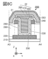
- Fig. 8B and Fig. 8C are cross-sectional views showing the configuration example of a semiconductor device.
- Fig. 9A is a plan view showing a configuration example of a semiconductor device
- Fig. 9B and Fig. 9C are cross-sectional views showing the configuration example of a semiconductor device.
- Fig. 9A is a plan view showing a configuration example of a semiconductor device
- Fig. 9B and Fig. 9C are cross-sectional views showing the configuration example of a semiconductor device.
- Fig. 9A is a plan view showing a configuration example of a semiconductor device
- FIG. 10A is a plan view showing a configuration example of a semiconductor device
- Fig. 10B and Fig. 10C are cross-sectional views showing the configuration example of a semiconductor device
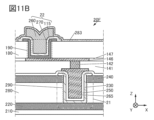
- 11A and 11B are cross-sectional views showing a configuration example of a semiconductor device.
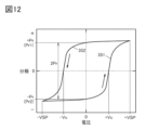
- FIG. 12 is a graph showing an example of a hysteresis characteristic.
- 13A and 13B are equivalent circuit diagrams of the semiconductor device
- Fig. 13C is a diagram illustrating Id-Vg characteristics of a transistor.
- 14A and 14B are timing charts and circuit diagrams illustrating the operation of the semiconductor device.
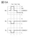
- 15A and 15B are timing charts and circuit diagrams illustrating the operation of the semiconductor device.
- 16A and 16B are timing charts and circuit diagrams illustrating the operation of the semiconductor device.
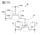
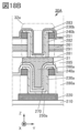
- FIG. 17A and 17B are cross-sectional views showing a configuration example of a semiconductor device, and Fig. 17C is an equivalent circuit diagram of the semiconductor device.
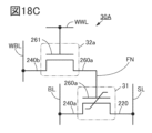
- 18A and 18B are cross-sectional views showing a configuration example of a semiconductor device, and Fig. 18C is an equivalent circuit diagram of the semiconductor device.
- 19A and 19B are cross-sectional views showing a configuration example of a semiconductor device, and Fig. 19C is an equivalent circuit diagram of the semiconductor device.
- 20A and 20B are cross-sectional views showing a configuration example of a semiconductor device, and Fig. 20C is an equivalent circuit diagram of the semiconductor device.
- FIG. 21 is a block diagram illustrating a configuration example of a semiconductor device.
- 22A and 22B are perspective views illustrating a configuration example of a semiconductor device.
- FIG. 23 is a block diagram illustrating the CPU.
- 24A and 24B are perspective views of a semiconductor device.
- 25A and 25B are perspective views of a semiconductor device.
- 26A and 26B are diagrams showing various storage devices by hierarchical level.
- 27A and 27B are diagrams illustrating an example of an electronic component.
- 28A and 28B are diagrams showing an example of electronic equipment, and
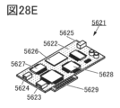
- FIGS. 28C to 28E are diagrams showing an example of a mainframe computer.
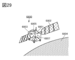
- FIG. 29 is a diagram showing an example of space equipment.
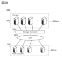
- FIG. 30 is a diagram illustrating an example of a storage system that can be applied to a data center.
- 31A and 31B are cross-sectional views illustrating a sample prepared in an example.
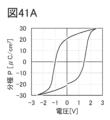
- 32A to 32D are diagrams showing P-V characteristics according to the example.
- 33A to 33C are diagrams showing P-V characteristics according to the example.
- 34A to 34D are diagrams showing the resistance to a rewrite test according to the embodiment.
- 35A to 35C are diagrams showing the resistance to a rewrite test according to an embodiment.
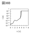
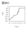
- 36A to 36D are diagrams showing I-V characteristics according to the example.
- 37A to 37C are diagrams showing I-V characteristics according to an example.
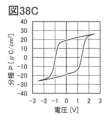
- 38A to 38C are diagrams showing P-E characteristics according to the example.
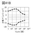
- 39A to 39C are diagrams showing fatigue characteristics according to an embodiment.
- 40A to 40C are diagrams showing the resistance to a rewrite test according to an embodiment.
- a semiconductor device is a device that utilizes semiconductor characteristics, and refers to a circuit including a semiconductor element (transistor, diode, photodiode, etc.), a device having such a circuit, etc. Also, it refers to any device that can function by utilizing semiconductor characteristics. For example, an integrated circuit, a chip including an integrated circuit, and an electronic component that houses a chip in a package are examples of semiconductor devices. Also, memory devices, display devices, light-emitting devices, lighting devices, electronic devices, etc. may themselves be semiconductor devices and may have semiconductor devices.
- the position, size, range, etc. of each component shown in the drawings, etc. may not represent the actual position, size, range, etc., in order to facilitate understanding of the invention. Therefore, the disclosed invention is not necessarily limited to the position, size, range, etc., disclosed in the drawings, etc.
- layers and resist masks, etc. may be unintentionally reduced by processes such as etching, but descriptions of this may be omitted in order to facilitate understanding of the invention.
- a resist mask is formed by a lithography method (photolithography, X-ray lithography, electron beam lithography, multiphoton lithography, interference lithography, nanoimprinting, etc.) and then an etching process (removal process) is performed, the resist mask is removed after the etching process is completed, unless otherwise specified.
- a lithography method photolithography, X-ray lithography, electron beam lithography, multiphoton lithography, interference lithography, nanoimprinting, etc.
- plan views also called “top views”
- oblique views some components may be omitted to make the invention easier to understand.
- Some hidden lines may also be omitted.
- ordinal numbers such as “first” and “second” are used to avoid confusion between components, and do not indicate any order or ranking, such as the order of processes or stacking. Even if a term does not have an ordinal number in this specification, ordinal numbers may be added in the claims to avoid confusion between components. The ordinal numbers added in this specification may differ from those added in the claims. Even if a term has an ordinal number in this specification, ordinal numbers may be omitted in the claims.
- electrode in this specification and the like do not functionally limit these components.
- electrode may be used as a part of “wiring”, and vice versa.
- the terms “electrode” and “wiring” include cases where multiple “electrodes” and “wiring” are integrated together.
- terminal may be used as a part of “wiring” or “electrode”, and vice versa.
- terminal includes cases where multiple “electrodes”, “wiring”, “terminals”, etc. are integrated together.
- an “electrode” can be a part of a “wiring” or “terminal”, and for example, a “terminal” can be a part of a “wiring” or “electrode”.
- terms such as “electrode”, “wiring”, and “terminal” may be replaced with terms such as "region” in some cases.
- supplying a signal means supplying a predetermined potential to wiring or the like. Therefore, it may be possible to read “signal” as a term such as “potential”. It may also be possible to read terms such as “potential” as a term such as “signal”. It may also be possible to read “signal” as a term such as “potential”.
- a “signal” may be a variable potential or a fixed potential. For example, it may be a power supply potential.
- film and “layer” can be interchanged depending on the circumstances.
- conductive layer can be changed to the term “conductive film.”
- insulating film can be changed to the term “insulating layer.”
- the term “capacitive element” may be, for example, a circuit element having a capacitance value higher than 0F, a region of a wiring having a capacitance value higher than 0F, a parasitic capacitance, or a gate capacitance of a transistor.
- the terms “capacitive element”, “parasitic capacitance”, or “gate capacitance” may be rephrased as the term “capacitance”.
- the term “capacitance” may be rephrased as the term “capacitive element”, “parasitic capacitance”, or “gate capacitance”.
- a “capacitance” (including a “capacitance” having three or more terminals) is configured to include an insulating layer and a pair of conductive layers sandwiching the insulating layer. Therefore, the term “pair of conductive layers" in “capacitance” may be rephrased as a “pair of electrodes", a “pair of conductive regions", a “pair of regions", or a “pair of terminals”. In addition, the term “one of the pair of terminals” may be referred to as “one terminal” or “first terminal”. In addition, the term “the other of the pair of terminals” may be referred to as “the other terminal” or “second terminal”. The value of the capacitance may be, for example, 0.05 fF or more and 10 pF or less. It may also be, for example, between 1 pF and 10 ⁇ F.
- source and drain of a transistor may be interchanged when transistors of different conductivity types are used, or when the direction of current changes during circuit operation. For this reason, in this specification, the terms “source” and “drain” can be used interchangeably.
- gate refers to a gate electrode and a part or all of a gate wiring.
- a gate wiring refers to a wiring that electrically connects the gate electrode of at least one transistor to another electrode or another wiring.
- source refers to a source region, a source electrode, and part or all of a source wiring.
- a source region refers to a region of a semiconductor layer whose resistivity is equal to or lower than a certain value.
- a source electrode refers to a conductive layer that includes a portion connected to a source region.
- a source wiring refers to wiring that electrically connects the source electrode of at least one transistor to another electrode or another wiring.
- drain refers to the drain region, drain electrode, and part or all of the drain wiring.
- the drain region refers to the region of the semiconductor layer whose resistivity is equal to or lower than a certain value.
- the drain electrode refers to the conductive layer that includes a portion connected to the drain region.
- the drain wiring refers to wiring that electrically connects the drain electrode of at least one transistor to another electrode or another wiring.
- the transistors shown in this specification are enhancement type (normally off type) field effect transistors.
- the threshold voltage (also referred to as "Vth") of the transistors is greater than 0V unless otherwise specified.
- the transistors shown in this specification are p-channel transistors, the Vth of the transistors is less than or equal to 0V unless otherwise specified.
- the Vth of multiple transistors of the same conductivity type is the same.
- off-state current refers to the current (also referred to as “drain current” or “Id”) that flows between the source and drain when the transistor is in an off state (also referred to as a “non-conducting state” or “cut-off state”).
- the off state refers to a state in which the potential difference (also referred to as “gate voltage” or “Vg") between the gate and source with respect to the source as the reference is lower than the threshold voltage in an n-channel transistor, and a state in which Vg is higher than the threshold voltage in a p-channel transistor.
- the off-state current of an n-channel transistor may refer to the drain current when Vg is lower than Vth.
- the term “leakage current” may be used to mean the same thing as “off-state current.”
- the term “off-state current” may refer to, for example, a current that flows between the source and drain when a transistor is in an off state.
- the on-current refers to Id when a transistor is in an on state (also called a "conducting state").
- the on-state refers to a state in which Vg is equal to or greater than Vth for an n-channel transistor, and a state in which Vg is equal to or less than the threshold voltage for a p-channel transistor.
- the on-current of an n-channel transistor may refer to the drain current when Vg is equal to or greater than Vth.
- VDD high power supply potential
- VSS low power supply potential
- GND ground potential GND
- voltage often refers to the potential difference between a certain potential and a reference potential (for example, ground potential or source potential). Also, “potential” is relative, and the potential applied to wiring, etc. may change depending on the reference potential. Therefore, “voltage” and “potential” can sometimes be used interchangeably.
- the terms “above,” “below,” “upward,” or “below” indicating the position of the components may be used for convenience in describing the positional relationship between the components with reference to the drawings. Furthermore, the positional relationship between the components may change as appropriate depending on the direction in which each configuration is depicted. Therefore, the terms are not limited to those described in the specification, and may be rephrased appropriately depending on the situation. For example, the expression “insulating layer located above the conductive layer” can be rephrased as “insulating layer located below the conductive layer” by rotating the orientation of the drawing shown by 180 degrees. For example, the expression “insulating layer located above the opening” may include “insulating layer located on the side of the opening.”
- electrode B on insulating layer A does not require that electrode B be formed in direct contact with insulating layer A, and does not exclude the inclusion of other components between insulating layer A and electrode B.
- overlap does not limit the state of the stacking order of components.
- electrode B overlapping insulating layer A does not limit the state in which electrode B is formed on insulating layer A, but does not exclude the state in which electrode B is formed under insulating layer A or the state in which electrode B is formed on the right (or left) side of insulating layer A.
- electrode B adjacent to insulating layer A does not require that insulating layer A and electrode B are formed in direct contact, and does not exclude the inclusion of other components between insulating layer A and electrode B.
- parallel refers to a state in which two straight lines are arranged at an angle of -10° or more and 10° or less. Therefore, it also includes cases where the angle is -5° or more and 5° or less.
- substantially parallel or “roughly parallel” refers to a state in which two straight lines are arranged at an angle of -30° or more and 30° or less.
- perpendicular refers to a state in which two straight lines are arranged at an angle of 80° or more and 100° or less. Therefore, it also includes cases where the angle is 85° or more and 95° or less.
- substantially perpendicular or “approximately perpendicular” refers to a state in which two straight lines are arranged at an angle of 60° or more and 120° or less.
- arrows indicating the X-direction, Y-direction, and Z-direction may be attached.
- the "X-direction” is the direction along the X-axis, and the forward direction and the reverse direction may not be distinguished unless explicitly stated. The same applies to the "Y-direction” and "Z-direction”.
- the X-direction, Y-direction, and Z-direction are directions that intersect with each other.
- the X-direction, Y-direction, and Z-direction are directions that are perpendicular to each other.
- one of the X-direction, Y-direction, and Z-direction may be called the "first direction” or “first direction”.
- the other may be called the “second direction” or “second direction”.
- the remaining one may be called the "third direction” or "third direction”.
- the conductive layer 260 may be divided into conductive layer 260a and conductive layer 260b.
- Figure 1A is a plan view of the semiconductor device 10.
- Figure 1B is a cross-sectional view of the portion indicated by the dashed line A1-A2 in Figure 1A, as viewed from the Y direction.
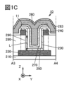
- Figure 1C is a cross-sectional view of the portion indicated by the dashed line A3-A4 in Figure 1A, as viewed from the X direction. Note that some elements have been omitted from the plan view of Figure 1A for clarity.
- the semiconductor device 10 has an insulating layer 210 on a substrate (not shown), a transistor 11 on the insulating layer 210, an insulating layer 280 on the insulating layer 210, and an insulating layer 283 on the transistor 11.
- the insulating layer 210, the insulating layer 280, and the insulating layer 283 function as interlayer films.
- Transistor 11 has a conductive layer 220, a conductive layer 240 on insulating layer 280, a semiconductor layer 230 on conductive layer 220, an insulating layer 250 on semiconductor layer 230, an insulating layer 270 on insulating layer 250, and a conductive layer 260 on insulating layer 270.
- the conductive layer 220 and the conductive layer 240 have regions that extend in the X direction.
- the extending direction of the conductive layer 220 and the extending direction of the conductive layer 240 may be different.
- the extending direction of the conductive layer 220 and the extending direction of the conductive layer 240 may be perpendicular to each other.
- An insulating layer 280 is provided on the conductive layer 220.
- An opening 290 is provided in the insulating layer 280 and the conductive layer 240, reaching the conductive layer 220. That is, the opening 290 is provided in a region overlapping a part of the conductive layer 220 in a plan view.
- the bottom of the opening 290 is the upper surface of the conductive layer 220
- the sidewalls of the opening 290 are the side surface of the insulating layer 280 and the side surface of the conductive layer 240.
- the opening 290 includes an opening in the insulating layer 280 and an opening in the conductive layer 240.
- the opening in the conductive layer 240 has a region overlapping with the opening in the insulating layer 280.
- At least some of the components of the transistor 11 are disposed in the opening 290.
- the semiconductor layer 230, the insulating layer 250, the insulating layer 270, and the conductive layer 260 are each disposed such that at least a portion of them is located in the opening 290.
- a semiconductor layer 230 is provided to cover the opening 290, an insulating layer 250 is provided to cover the semiconductor layer 230, an insulating layer 270 is provided to cover the insulating layer 250, and a conductive layer 260 is provided to fill the recess of the insulating layer 270 that reflects the shape of the opening 290.
- the portions of the semiconductor layer 230, the insulating layer 250, the insulating layer 270, and the conductive layer 260 that are arranged in the opening 290 are provided to reflect the shape of the opening 290.
- the semiconductor layer 230 has a region that overlaps with the bottom of the opening 290 and a region that overlaps with the side of the opening 290. That is, in the opening 290, the semiconductor layer 230 has a region that contacts the upper surface of the conductive layer 220, a region that contacts the side of the insulating layer 280, and a region that contacts the side of the conductive layer 240.
- the semiconductor layer 230 also has a region that contacts the upper surface of the conductive layer 240. That is, a part of the semiconductor layer 230 is electrically connected to the conductive layer 220, and another part of the semiconductor layer 230 is electrically connected to the conductive layer 240.
- the thickness of the semiconductor layer 230 is preferably 1 nm or more, 3 nm or more, or 5 nm or more, and 20 nm or less, 15 nm or less, 12 nm or less, or 10 nm or less.
- the thickness of the insulating layer 250 is preferably 0.5 nm or more and 15 nm or less, more preferably 0.5 nm or more and 12 nm or less, and even more preferably 0.5 nm or more and 10 nm or less. It is sufficient that at least a portion of the insulating layer 250 has a region with the above-mentioned thickness.
- the thickness of the insulating layer 270 is preferably 20 nm or less, and more preferably 10 nm or less (typically, 2 nm or more and 9 nm or less).
- the thickness of the insulating layer 270 is preferably 8 nm or more and 12 nm or less. It is sufficient that at least a portion of the insulating layer 270 has a region with the above-mentioned thickness.
- the semiconductor film that becomes the semiconductor layer 230, the insulating film that becomes the insulating layer 250, and the insulating film that becomes the insulating layer 270 are preferably formed using the atomic layer deposition (ALD) method. As described above, the semiconductor film that becomes the semiconductor layer 230, the insulating film that becomes the insulating layer 250, and the insulating film that becomes the insulating layer 270 are preferably formed with a thin film thickness, and it is necessary to make the film thickness variation small.
- ALD atomic layer deposition
- the ALD method is a film formation method in which a precursor and a reactant (e.g., an oxidizing agent, etc.) are alternately introduced, and the film thickness can be adjusted by the number of times this cycle is repeated, so that precise film thickness adjustment is possible.
- the ALD method can deposit layers of atoms one by one on the bottom and side of the opening 290, so that the semiconductor film that becomes the semiconductor layer 230, the insulating film that becomes the insulating layer 250, and the insulating film that becomes the insulating layer 270 can be formed with good coverage on the opening 290.
- the conductive layer 260 has a region that extends beyond the end of the insulating layer 270.
- the conductive layer 260 has a region that extends in the Y direction.
- the semiconductor layer 230 has a region that functions as a semiconductor layer (semiconductor layer including a channel formation region) in which the channel of the transistor 11 is formed, the conductive layer 260 has a region that functions as the gate electrode of the transistor 11, and the insulating layer 250 and the insulating layer 270 have a region that functions as the gate insulating layer of the transistor 11.
- the gate insulating layer may be called a gate insulating film or a gate insulator.
- the conductive layer 220 has a region that functions as one of the source electrode and drain electrode of the transistor 11, and the conductive layer 240 has a region that functions as the other of the source electrode and drain electrode of the transistor 11. For example, when the conductive layer 220 has a region that functions as the drain electrode of the transistor 11, the conductive layer 240 has a region that functions as the source electrode of the transistor 11.
- the channel of transistor 11 is formed in semiconductor layer 230 between the region of semiconductor layer 230 that contacts conductive layer 220 and the region that contacts conductive layer 240. Therefore, it can be said that transistor 11 is provided in a region that includes opening 290.
- the source electrode and drain electrode of transistor 11 are arranged in the Z direction. That is, the source and drain of transistor 11 are arranged at different heights. In other words, the source and drain of transistor 11 are arranged at different positions in the Z direction.
- Such a transistor is also called a “vertical channel transistor,” “vertical channel transistor,” “vertical transistor,” or “VFET (Vertical Field Effect Transistor).”
- the source electrode and the drain electrode are arranged in the Z direction. That is, the channel formation region, the source region, and the drain region are arranged in the Z direction.
- a vertical channel transistor can occupy a smaller area than a planar transistor in which the channel formation region, the source region, and the drain region are provided separately on the XY plane.
- the area occupied by the semiconductor device can be reduced.
- high integration of the semiconductor device can be achieved. For example, the memory capacity per unit area of a memory device using the semiconductor device can be increased.
- FIG. 1D shows a cross-sectional view of the area indicated by the dashed line B1-B2 in FIG. 1B as viewed from the Z direction.
- FIG. 1D can also be said to be a cross-sectional view in the XY plane including the insulating layer 280.
- the insulating layer 280 contacts the entire outer periphery of the semiconductor layer 230. Therefore, the channel formation region of the transistor 11 can be formed on the entire outer periphery of the portion of the semiconductor layer 230 that is formed in the same layer as the insulating layer 280. Note that FIG. 1D can also be considered a cross-sectional view in the XY plane that includes the channel formation region of the semiconductor layer 230.
- the semiconductor layer 230, the insulating layer 250, the insulating layer 270, and the conductive layer 260 are arranged concentrically. Therefore, the side of the conductive layer 260 arranged at the center faces the side of the semiconductor layer 230 through the insulating layer 270 and the insulating layer 250. That is, in a plan view, the entire circumference of the semiconductor layer 230 becomes a channel formation region.
- the channel width of the transistor 11 is determined by the length of the outer circumference of the semiconductor layer 230. That is, it can be said that the channel width of the transistor 11 is determined by the size of the maximum width of the opening 290 (the maximum diameter when the opening 290 is circular in a plan view). In FIG.
- the maximum width D of the opening 290 is indicated by a double-headed arrow with a two-dot chain line
- the channel width W of the transistor 11 is indicated by a double-dot chain line with a one-dot chain line with a two-dot chain line.
- the maximum width D of the opening 290 is set by the exposure limit of photolithography.
- the maximum width D of the opening 290 is set by the film thickness of each of the semiconductor layer 230, the insulating layer 250, the insulating layer 270, and the conductive layer 260 provided in the opening 290.
- the maximum width D of the opening 290 is, for example, 5 nm or more, 10 nm or more, or 20 nm or more, and is preferably 100 nm or less, 60 nm or less, 50 nm or less, 40 nm or less, or 30 nm or less. Note that when the opening 290 is circular in plan view, the maximum width D of the opening 290 corresponds to the diameter of the opening 290, and the channel width W can be calculated as "D x ⁇ ".
- the semiconductor layer 230, the insulating layer 250, the insulating layer 270, and the conductive layer 260 are arranged concentrically. This makes the distance between the conductive layer 260 and the semiconductor layer 230 roughly uniform, so that a gate electric field can be applied roughly uniformly to the semiconductor layer 230.
- the opening 290 is circular in plan view, but the present invention is not limited to this.
- the opening 290 may be approximately circular such as an ellipse, polygonal such as a rectangle, or polygonal such as a rectangle with rounded corners in plan view.
- the maximum width of the opening 290 can be calculated appropriately according to the shape of the top of the opening 290. For example, if the opening is rectangular in plan view, the maximum width of the opening 290 can be the length of the diagonal line at the top of the opening 290.
- the channel length of transistor 11 is the distance between the source region and the drain region. In other words, it can be said that the channel length of transistor 11 is determined by the thickness of insulating layer 280 on conductive layer 220.
- the channel length L of transistor 11 is indicated by a dashed double-headed arrow. In a cross-sectional view, channel length L is the distance between the end of the region where semiconductor layer 230 and conductive layer 220 contact, and the end of the region where semiconductor layer 230 and conductive layer 240 contact. In other words, channel length L corresponds to the length of the side of insulating layer 280 on the opening 290 side in a cross-sectional view.
- the channel length is limited by the exposure limit of photolithography, making further miniaturization difficult, but in the present invention, the channel length can be set by the film thickness of the insulating layer 280. Therefore, the channel length of the transistor 11 can be made into a very fine structure (e.g., 60 nm or less, 50 nm or less, 40 nm or less, 30 nm or less, 20 nm or less, or 10 nm or less, and 0.1 nm or more, 1 nm or more, or 5 nm or more) that is less than the exposure limit of the photolithography device used for processing. This increases the on-current of the transistor 11, and improves the frequency characteristics. By using a vertical channel transistor, a semiconductor device with high operating speed can be provided.
- the channel length L is determined according to the thickness of the insulating layer 280, a transistor with a short channel length L can be manufactured with high precision.
- the characteristic variation between multiple transistors 11 is also reduced. This makes it possible to stabilize the operation of a semiconductor device including the transistors 11 and improve reliability.
- reduced characteristic variation increases the degree of freedom in the circuit design of the semiconductor device and allows the operating voltage to be reduced. This allows the power consumption of the semiconductor device to be reduced.
- a channel formation region, a source region, and a drain region can be formed in the opening 290. This allows the area occupied by the transistor 11 to be reduced compared to a planar transistor in which the channel formation region, the source region, and the drain region are provided separately on the XY plane. This allows the semiconductor device to be highly integrated. Furthermore, when the semiconductor device of one embodiment of the present invention is used in a memory device, the memory capacity per unit area can be increased.
- the side surfaces of the insulating layer 280 and the conductive layer 240 in the opening 290 may be tapered.
- the taper angle of the side surfaces of the insulating layer 280 and the conductive layer 240 in the opening 290 (the taper angle of the side surface of the opening 290) is set to 45° or more and 90° or less, preferably 50° or more and 75° or less.
- the taper angle of the side surface of a layer refers to the angle between the bottom surface of the layer and the side surface.
- the coverage of the semiconductor layer 230, the insulating layer 250, the insulating layer 270, and the conductive layer 260 formed in the opening 290 can be improved.
- the area occupied by the transistor 11 can be reduced.
- the channel length L of the transistor 11 is preferably shorter than at least the channel width W of the transistor 11.
- the channel length L of the transistor 11 according to one embodiment of the present invention is 0.1 to 0.99 times, preferably 0.5 to 0.8 times, the channel width W of the transistor 11.
- the semiconductor layer 230 is shown divided in the X direction, but the present invention is not limited to this.
- the semiconductor layer 230 may be provided extending in the X direction.
- the semiconductor layer 230 is divided in the Y direction (see FIG. 2B).
- the ends of the semiconductor layer 230 and the conductive layer 240 are aligned.
- the semiconductor film that becomes the semiconductor layer 230 and the conductive film that becomes the conductive layer 240 can be processed continuously using the same etching mask, thereby improving the productivity of the semiconductor device.
- a material that can have ferroelectricity is used as the insulating layer 270.
- the insulating layer 270 has ferroelectricity. Therefore, the transistor 11 functions as an FeFET (Ferroelectric Field Effect Transistor).
- the threshold voltage of the FeFET is determined according to the polarization generated in the gate insulating layer.
- materials that can have ferroelectricity refers to a material that can have hysteresis characteristics in the relationship between the strength of the electric field (electric field strength) applied to the material and the magnitude of polarization, or a material in which polarization can occur spontaneously even in the absence of an external electric field (an electric field applied to the material from the outside). Therefore, materials that can have ferroelectricity include materials that have one or more of ferroelectricity, antiferroelectricity, and ferroelectricity.
- a layer of a material that can have ferroelectricity may be referred to as a ferroelectric layer.
- a device having such a ferroelectric layer may be referred to as a ferroelectric device.
- Examples of materials that may have ferroelectric properties include oxides containing either or both of hafnium and zirconium.
- oxides containing either or both of hafnium and zirconium include hafnium oxide, zirconium oxide, and hafnium zirconium oxide.
- the insulating layer 270 in order for the insulating layer 270 to exhibit ferroelectricity, the insulating layer 270 must contain crystals.
- the insulating layer 270 is preferably one that contains crystals having an orthorhombic (space group: Pca2 1 ) crystal structure, since ferroelectricity is exhibited.
- the remanent polarization can be increased.
- an element that increases the oxygen vacancy concentration in the oxide is added to an oxide having one or both of hafnium and zirconium.
- the element there is a Group 3 element (also called Group IIIa element) in the periodic table.
- the Group 3 element in the periodic table added to the oxide is more preferably one or more selected from scandium, lanthanum, and yttrium, and even more preferably one or both of lanthanum and yttrium.
- the Group 3 element in the periodic table may be simply called the Group 3 element.
- hafnium and zirconium tend to have a valence of +4.
- Group 3 elements tend to have a valence of +3. Therefore, by adding an element with a different valence from hafnium and zirconium to an oxide containing either or both of hafnium and zirconium, the concentration of oxygen vacancies in the oxide can be increased.
- the grain size of the crystals contained in the oxide By reducing the grain size of the crystals contained in the oxide and reducing the grain size variation, the dielectric breakdown voltage of the oxide increases, making it possible to achieve high voltage resistance. In addition, it is possible to reduce the amount of leakage current.
- the oxide may be more likely to produce crystals having an orthorhombic crystal structure than crystals having a monoclinic crystal structure. This is presumably due to the addition of an element with an ionic radius larger than those of hafnium and zirconium. From this point of view, lanthanum and yttrium are particularly preferable as the Group 3 element to be added to the above oxide.
- the content of the Group 3 element added to the oxide having one or both of hafnium and zirconium is preferably 0.1 atomic% to 10 atomic%, more preferably 0.1 atomic% to 5 atomic%, and even more preferably 0.1 atomic% to 3 atomic%.
- the content of the Group 3 element refers to the ratio of the number of atoms of the Group 3 element to the sum of the number of atoms of all metal elements contained in the ferroelectric layer.
- the insulating layer 270 preferably contains one or both of hafnium and zirconium, at least one Group 3 element, and oxygen, more preferably contains hafnium, zirconium, at least one Group 3 element, and oxygen, and even more preferably contains hafnium, zirconium, one or both of lanthanum and yttrium, and oxygen.
- the insulating layer 270 preferably uses an oxide containing one or both of hafnium and zirconium to which at least one Group 3 element has been added, more preferably uses hafnium zirconium oxide to which at least one Group 3 element has been added, and even more preferably uses hafnium zirconium oxide to which one or both of lanthanum and yttrium have been added.
- the content of at least one of the group 3 elements in the insulating layer 270 is preferably 0.1 atomic% to 10 atomic%, more preferably 0.1 atomic% to 5 atomic%, and even more preferably 0.1 atomic% to 3 atomic%.
- the content of lanthanum in the insulating layer 270 is preferably in the above range.
- the sum of the content of lanthanum and the content of yttrium in the insulating layer 270 is preferably in the above range.
- the insulating film that becomes the insulating layer 270 is preferably formed using the ALD method.
- a film of any composition can be formed by simultaneously introducing multiple different types of precursors.
- a film of any composition can be formed by controlling the number of cycles of each precursor.
- an oxide in which the content of at least one of the group 3 elements is within the above range can be formed.
- an oxide having one or both of hafnium and zirconium may be formed, followed by forming an oxide having at least one Group 3 element, and then performing a heat treatment to form an oxide having one or both of hafnium and zirconium and at least one Group 3 element.
- an oxide having at least one Group 3 element may be formed, followed by forming an oxide having one or both of hafnium and zirconium, and then performing a heat treatment to form an oxide having one or both of hafnium and zirconium and at least one Group 3 element.
- an oxide containing one or both of hafnium and zirconium may be formed, and a treatment for adding a Group 3 element may be performed to form an oxide containing one or both of hafnium and zirconium and at least one Group 3 element.
- oxygen vacancies may be formed in the oxide containing one or both of hafnium and zirconium during the treatment for adding the Group 3 element.
- the addition of the Group 3 element can promote an increase in the concentration of oxygen vacancies in the oxide.
- the treatment for adding the Group 3 element can be performed, for example, by ion doping or ion implantation.
- the insulating layer 270 may be a single layer or a multilayer of a material that can have ferroelectricity, as described below under [Insulating layer].
- Figure 1E shows an equivalent circuit diagram of the semiconductor device 10.
- one of the source and drain of the transistor 11 is electrically connected to wiring SL
- the other of the source and drain of the transistor 11 is electrically connected to wiring BL
- the gate of the transistor 11 is electrically connected to wiring WL.
- the semiconductor device 10 functions as a memory circuit (also called a "memory element” or “memory cell”).
- Figure 1E is an equivalent circuit diagram when the transistor 11 includes a ferroelectric.
- the conductive layer 220 functions as at least a part of the wiring SL.
- the conductive layer 240 functions as at least a part of the wiring BL.
- the conductive layer 260 functions as at least a part of the wiring WL. Note that the wiring SL and the wiring BL can be interchanged.
- the conductive layer 220 may function as at least a part of the wiring BL, and the conductive layer 240 may function as at least a part of the wiring SL.
- the conductive layer 260 is preferably made of a conductive material having a function of absorbing oxygen. Since the conductive layer 260 is in contact with the insulating layer 270, by using a conductive material having a function of absorbing oxygen as the conductive layer 260, oxygen can be absorbed from the insulating layer 270, and the oxygen vacancy concentration in the insulating layer 270 can be increased. Therefore, the residual polarization can be increased.
- conductive materials having a function of absorbing oxygen include metal elements, alloys containing metal elements, and alloys combining metal elements. In addition, oxides of the alloys may be used as alloys containing the above-mentioned metal elements.
- tungsten, molybdenum, ruthenium, titanium, tantalum, and the like can be mentioned. These conductive materials are also conductive materials that do not contain nitrogen. In this specification, etc., a conductive material that does not contain nitrogen refers to a conductive material with a nitrogen concentration of 1 atomic % or less.
- tungsten is a highly conductive material and can be suitably used for the conductive layer 260.
- ruthenium is suitable for use for the conductive layer 260 because its oxide is also conductive. Therefore, it is preferable to use tungsten or ruthenium for the conductive layer 260.
- the oxygen in the insulating layer 270 diffuses into the conductive layer 260. Therefore, the oxygen vacancy concentration in the insulating layer 270 has a gradient in the direction from the conductive layer 260 side to the insulating layer 250 side. In other words, it can be said that the direction in which oxygen vacancies are generated is the same as the direction from the conductive layer 260 side to the insulating layer 250 side.
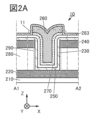
- a layer 267 may be formed between the insulating layer 270 and the conductive layer 260 as shown in FIG. 2C.
- the layer 267 contains metal MX and oxygen.
- the oxygen concentration of the layer 267 is higher than the oxygen concentration of the conductive layer 260.
- the concentration of metal MX in the layer 267 is lower than the concentration of metal MX in the conductive layer 260.
- Layer 267 may be conductive or insulating. When layer 267 is conductive, layer 267 has a region that functions as a gate electrode of transistor 11. When layer 267 is insulating, layer 267 has a region that functions as a gate insulating layer of transistor 11.
- a conductive material containing nitrogen can be used as the conductive layer 260.
- conductive materials containing nitrogen include tantalum nitride, titanium nitride, nitrides containing titanium and aluminum, nitrides containing tantalum and aluminum, and ruthenium nitride.
- the conductive layer 260 may be made of a conductive material that is not easily oxidized or that has a function of suppressing the diffusion of oxygen.
- conductive materials include conductive materials that contain nitrogen (e.g., titanium nitride or tantalum nitride) and conductive materials that contain oxygen (e.g., ruthenium oxide). This can suppress a decrease in the conductivity of the conductive layer 260.
- the conductive material described in the section [Conductive Layer] below may be used as the conductive layer 260 in a single layer or multilayer configuration.
- the semiconductor layer 230 is provided inside the opening in the insulating layer 280. Since the transistor 11 is a vertical channel type transistor, a channel is formed along the side of the opening in the insulating layer 280.
- the semiconductor materials described in the [Semiconductor layer] below can be used in a single layer or a stacked layer.
- the semiconductor layer 230 of the transistor 11 it is particularly preferable to use a metal oxide (also called an oxide semiconductor) that functions as a semiconductor.
- a transistor using an oxide semiconductor for the semiconductor layer 230 may have fluctuating electrical characteristics and poor reliability if oxygen vacancies ( VO ) and impurities are present in a channel formation region in the oxide semiconductor.
- a defect in which hydrogen is introduced into an oxygen vacancy (hereinafter sometimes referred to as VOH ) may generate electrons that serve as carriers. For this reason, if an oxygen vacancy is present in the channel formation region in the oxide semiconductor, the OS transistor is likely to have normally-on characteristics. Therefore, it is preferable that oxygen vacancies and impurities are reduced as much as possible in the channel formation region in the oxide semiconductor. In other words, it is preferable that the carrier concentration in the channel formation region in the oxide semiconductor is reduced and the channel formation region in the oxide semiconductor is made i-type (intrinsic) or substantially i-type.
- the normally-on characteristic refers to a state in which a channel exists and current flows through the transistor even when no voltage is applied to the gate.
- the normally-off characteristic refers to a state in which no current flows through the transistor when no potential is applied to the gate or when a ground potential is applied to the gate.
- the source and drain regions of an OS transistor are preferably regions having more oxygen vacancies, more VOH , or a higher concentration of impurities such as hydrogen, nitrogen, or metal elements than the channel formation region, thereby increasing the carrier concentration and lowering the resistance. That is, the source and drain regions of an OS transistor are preferably n-type regions having a higher carrier concentration and lower resistance than the channel formation region.
- the insulating layer 210 and the insulating layer 280 function as an interlayer film, it is preferable that they have a low dielectric constant. By using a material with a low dielectric constant as the interlayer film, the parasitic capacitance that occurs between wirings can be reduced.
- a single layer or a stack of insulating layers containing a material with a low dielectric constant, as described below in [Insulating layer] can be used. Silicon oxide and silicon oxynitride are preferable because they are thermally stable.
- the concentrations of impurities such as water and hydrogen in the insulating layer 210 and the insulating layer 280 are reduced. This makes it possible to suppress the intrusion of impurities such as water and hydrogen into the channel formation region of the semiconductor layer 230.
- the insulating layer 280 disposed in the vicinity of the channel formation region is preferably an insulator containing oxygen that is desorbed by heating (hereinafter may be referred to as excess oxygen).
- excess oxygen By performing heat treatment on the insulating layer 280 containing excess oxygen, oxygen can be supplied from the insulating layer 280 to the channel formation region of the semiconductor layer 230, thereby reducing oxygen vacancies and VOH . This can stabilize the electrical characteristics of the transistor 11 and improve its reliability.
- an insulator having a function of capturing or fixing hydrogen as described in [Insulating Layer] below, may be used. With such a structure, hydrogen in the semiconductor layer 230 is captured or fixed by the insulating layer 280, so that the hydrogen concentration in the semiconductor layer 230 can be reduced.
- the insulating layer 280 magnesium oxide, aluminum oxide, or the like can be used.
- the insulating layer 280 may be a barrier insulator against hydrogen, as described below in [Insulating layer]. By having the insulating layer 280 provided on the outside of the semiconductor layer 230 have barrier properties against hydrogen, the diffusion of hydrogen into the semiconductor layer 230 can be suppressed.
- the insulating material described in the [Insulating Layer] below may be used as each of the insulating layer 210 and the insulating layer 280, either in a single layer or in a multilayer configuration.
- Insulating layer 280 is shown as a single layer in Figures 1B and 1C, but the present invention is not limited to this. Insulating layer 280 may have a laminated structure.
- Figures 3A and 3B are cross-sectional views of the semiconductor device 10. Note that FIG. 1A can be referred to for plan views of the semiconductor device 10 shown in Figures 3A and 3B.
- the insulating layer 280 may have a laminated structure of an insulating layer 280_1, an insulating layer 280_2 on the insulating layer 280_1, and an insulating layer 280_3 on the insulating layer 280_2.
- the insulating layer 280_1 has a region in contact with the upper surface of the insulating layer 210 and a region in contact with the side and upper surface of the conductive layer 220.
- the insulating layer 280_3 has a region in contact with the lower surface of the conductive layer 240.
- the insulating layer 280_2 is preferably made of an insulator containing excess oxygen. It is also preferably formed using a material with a low dielectric constant. By forming the insulating layer 280_2 using a material with a low dielectric constant, the parasitic capacitance generated between wirings can be reduced. Specifically, silicon oxide or silicon oxynitride can be used as the insulating layer 280_2.
- the insulating layer 280_1 and the insulating layer 280_3 are preferably made of a barrier insulator against oxygen, as described in the insulating layer section below.
- the insulating layer 280_1 between the insulating layer 280_2 and the conductive layer 220 the conductive layer 220 can be prevented from being oxidized and the resistance of the conductive layer 220 can be prevented from increasing.
- the insulating layer 280_3 between the insulating layer 280_2 and the conductive layer 240 the conductive layer 240 can be prevented from being oxidized and the resistance of the conductive layer 240 can be prevented from increasing.
- the insulating layer 280_1 and the insulating layer 280_3 may be made of the same material or different materials.
- silicon nitride can be used for the insulating layer 280_1 and the insulating layer 280_3, and silicon oxide or silicon oxynitride can be used for the insulating layer 280_2.
- each of the insulating layer 280_1 and the insulating layer 280_3 contains at least silicon and nitrogen.
- the insulating layer 280_2 contains at least silicon and oxygen.
- Insulators having a function of capturing or fixing hydrogen may be used as insulating layer 280_1.
- Such a structure can suppress diffusion of hydrogen from below insulating layer 280_1 to semiconductor layer 230, and can further capture or fix hydrogen contained in semiconductor layer 230.
- the hydrogen concentration in semiconductor layer 230 can be reduced.
- a laminated film of aluminum oxide and silicon nitride on the aluminum oxide may be used as insulating layer 280_1.
- an insulator having a function of capturing or fixing hydrogen may be used as insulating layer 280_3.
- a material containing hydrogen may be used as the insulating layer 280_1 and the insulating layer 280_3.
- the semiconductor layer 230 in the region in contact with the insulating layer becomes n-type and can function as a source region or a drain region.
- a material containing silicon, nitrogen, and hydrogen may be used as the insulating layer.
- silicon nitride containing hydrogen or silicon nitride oxide containing hydrogen may be used.
- the thickness of the insulating layer 280_1 and the insulating layer 280_3 is preferably 1 nm or more and 15 nm or less, more preferably 2 nm or more and 10 nm or less, more preferably 3 nm or more and 7 nm or less, and further preferably 3 nm or more and 5 nm or less.
- the thickness of the insulating layer 280_2 is preferably 1 nm or more and 50 nm or less, more preferably 2 nm or more and 30 nm or less, and even more preferably 3 nm or more and 20 nm or less.
- 3A and 3B show a structure in which the insulating layer 280_3 is provided on the planarized insulating layer 280_2, but the present invention is not limited to this.
- the insulating layer 280_3 may be formed without performing planarization treatment on the insulating layer 280_2. By not performing the planarization treatment, the manufacturing cost can be reduced and the production yield can be increased.
- the insulating layers 280_1, 280_2, and 280_3 can be successively formed without exposure to the air environment.
- the insulating layers 280_1 to 280_3 By forming the insulating layers 280_1 to 280_3 without exposing them to the air, impurities or moisture from the air environment can be prevented from adhering to the insulating layers 280_1 to 280_3, and the vicinity of the interface between the insulating layers 280_1 and 280_2 and the vicinity of the interface between the insulating layers 280_2 and 280_3 can be kept clean.
- the insulating layer 280 is shown in FIGS. 3A and 3B as having a three-layer laminate structure, the present invention is not limited to this.
- the insulating layer 280 may also have a two-layer or four or more layer laminate structure.
- the insulating layer 250 is preferably made of a barrier insulator against oxygen, as described in [Insulating Layer] below.
- the insulating layer 250 has a region in contact with the semiconductor layer 230.
- the insulating layer 250 has a barrier property against oxygen, and thus can suppress the desorption of oxygen from the semiconductor layer 230 during heat treatment or the like. Thus, the formation of oxygen vacancies in the semiconductor layer 230 can be suppressed. This can improve the electrical characteristics of the transistor 11 and improve its reliability.
- aluminum oxide or hafnium oxide is preferably used as the insulating layer 250.
- Aluminum oxide and hafnium oxide have the function of capturing or fixing hydrogen. Thus, the hydrogen concentration in the semiconductor layer 230 in contact with the insulating layer 250 can be reduced.
- silicon nitride may be used as the insulating layer 250.
- a barrier insulator against oxygen for the insulating layer 250 provided between the conductive layer 260 and the insulating layer 280, it is possible to prevent the oxygen contained in the insulating layer 280 from diffusing into the conductive layer 260, and to suppress the oxidation of the conductive layer 260. In addition, it is possible to suppress a decrease in the amount of oxygen supplied from the insulating layer 280 to the semiconductor layer 230.
- the insulating layer 270 functions as a gate insulating layer of the transistor 11.
- a ferroelectric is used for the insulating layer 270, an unintended current (leakage current) is likely to flow between the conductive layer 260 and the semiconductor layer 230. Therefore, it is preferable to use a paraelectric material as the insulating layer 250 provided between the semiconductor layer 230 and the insulating layer 270.
- a paraelectric material refers to a material that is polarized by applying a voltage and then disappears when the application of the voltage is stopped.
- an increase in leakage current can be prevented.
- aluminum oxide is a paraelectric material, it is suitable for the insulating layer 250. When aluminum oxide is used as the insulating layer 250, the insulating layer 250 has at least aluminum and oxygen.
- the insulating layer 250 may be a single layer or a multilayer of the insulating material described in the section [Insulating layer] below.
- Insulating layer 250 is shown as a single layer in FIGS. 1B and 1C, but the present invention is not limited to this. Insulating layer 250 may have a laminated structure.
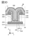
- Figures 3C and 3D are cross-sectional views of the semiconductor device 10. Note that FIG. 1A can be referred to for plan views of the semiconductor device 10 shown in Figures 3C and 3D.
- the insulating layer 250 may have a laminated structure of an insulating layer 250_1 and an insulating layer 250_2 on the insulating layer 250_1.
- the insulating layer 250_1 has a region in contact with the upper surface of the semiconductor layer 230 and a region in contact with the upper surface and side surfaces of the conductive layer 240.
- the insulating layer 250_2 has a region in contact with the lower surface of the insulating layer 270, a region in contact with the lower surface of the conductive layer 260, and a region in contact with the lower surface of the insulating layer 283.
- the insulating layer 250_1 is preferably an insulator having a function of capturing or fixing hydrogen, as described in [Insulating Layer] below.
- the insulating layer 250_2 is preferably an insulator that acts as a barrier against oxygen, as described in [Insulating Layer] below. With such a structure, the hydrogen concentration in the semiconductor layer 230 can be reduced. Furthermore, oxygen can be prevented from being released from the semiconductor layer 230. Furthermore, oxidation of the conductive layer 260 can be prevented.
- the insulating layer 250 in FIG. 3C and FIG. 3D has a two-layer laminated structure, the present invention is not limited to this.
- the insulating layer 250 may have a three or more layer laminated structure.
- the conductive layer 220 can be a single layer or a stack of conductors described in the conductive layer section described below.
- a conductive material with high conductivity such as tungsten, can be used as the conductive layer 220.
- the conductivity of the conductive layer 220 can be improved, allowing it to function sufficiently as a wiring.
- the conductive layer 220 is preferably made of a conductive material that is not easily oxidized, a conductive material that has a function of suppressing the diffusion of oxygen, or a conductive material that contains oxygen, either in a single layer or in a laminated form.
- a conductive material that is not easily oxidized titanium nitride or indium tin oxide with added silicon may be used.
- a structure in which titanium nitride is laminated on tungsten may be used.
- a structure in which tungsten is laminated on a first titanium nitride, and a second titanium nitride is laminated on the tungsten may be used.
- the conductive layer 240 may be a single layer or a laminate of the conductors described in the section [Conductive layer] below.
- ruthenium is a material that has good contact resistance with the semiconductor layer 230, and therefore can be preferably used.
- oxide of ruthenium is also conductive, it has good conductivity even when the surface is oxidized during the manufacturing process, and therefore can be preferably used.
- a highly conductive material such as tungsten may be used as the conductive layer 240.
- the conductive layer 240 may be made of a conductive material that is not easily oxidized, a conductive material that has a function of suppressing the diffusion of oxygen, or a conductive material that contains oxygen.
- a conductive material that contains oxygen for example, titanium nitride or tantalum nitride may be used. With this configuration, excessive oxidation of the conductive layer 240 by the semiconductor layer 230 can be suppressed.
- the conductive layer 220 in contact with the semiconductor layer 230 and the conductive layer 240 in contact with the semiconductor layer 230 may be made of a conductive material that makes the oxide semiconductor n-type.
- a conductive material containing nitrogen may be used.
- a conductive material containing titanium or tantalum and nitrogen may be used.
- another conductive material may be provided on top of the conductive material containing nitrogen.
- the region of the semiconductor layer 230 in contact with the conductive layer 220 functions as one of the source region and the drain region
- the region of the semiconductor layer 230 in contact with the conductive layer 240 functions as the other of the source region and the drain region.
- insulating layer 283 it is preferable to use an insulator having barrier properties against hydrogen, as described below in [Insulating Layer]. This makes it possible to suppress the diffusion of hydrogen from above the insulating layer 283 into the semiconductor layer 230. Silicon nitride films and silicon nitride oxide films each have the characteristics of releasing little impurities (e.g., water and hydrogen) from themselves and being difficult for oxygen and hydrogen to permeate, and therefore can be suitably used for the insulating layer 283.
- impurities e.g., water and hydrogen
- the insulating layer 283 it is preferable to use an insulator having a function of capturing hydrogen or fixing hydrogen, as described in [Insulating Layer] below, as the insulating layer 283. With such a structure, it is possible to suppress diffusion of hydrogen from above the insulating layer 283 to the semiconductor layer 230. Furthermore, since hydrogen in the semiconductor layer 230 is captured or fixed by the insulating layer 283, the hydrogen concentration in the semiconductor layer 230 can be reduced.
- magnesium oxide, aluminum oxide, hafnium oxide, or the like can be used. Also, for example, a stacked film of aluminum oxide and silicon nitride on the aluminum oxide may be used as the insulating layer 283.
- an insulating layer having the function of capturing or fixing hydrogen may be provided below the conductive layer 220.
- Figures 4A and 4B are cross-sectional views of the semiconductor device 10.
- an insulating layer 212 is provided below the conductive layer 220.
- the insulating layer 212 is provided between the insulating layer 210 and the insulating layer 280 and conductive layer 220.
- the insulating layer 212 is provided on the insulating layer 210, and the conductive layer 220 and the insulating layer 280 are provided on the insulating layer 212.
- the insulating layer 212 is preferably made of an insulator having the function of capturing or fixing hydrogen, as described in the section [Insulating Layer] below.
- hydrogen in the semiconductor layer 230 can diffuse to the insulating layer 212 through the conductive layer 220, and the hydrogen can be captured or fixed by the insulating layer 212. Therefore, the hydrogen concentration in the semiconductor layer 230 can be reduced.
- the substrate can be determined in consideration of the presence or absence of light transmission and the heat resistance to a degree that can withstand heat treatment, depending on the purpose.
- an insulating substrate, a semiconductor substrate, or a conductive substrate may be used.
- a glass substrate such as barium borosilicate glass and aluminoborosilicate glass
- a ceramic substrate such as barium borosilicate glass and aluminoborosilicate glass
- a ceramic substrate such as barium borosilicate glass and aluminoborosilicate glass
- a ceramic substrate such as barium borosilicate glass and aluminoborosilicate glass
- a ceramic substrate such as barium borosilicate glass and aluminoborosilicate glass
- a ceramic substrate such as barium borosilicate glass and aluminoborosilicate glass
- a ceramic substrate such as barium borosilicate glass and aluminoborosilicate glass
- a ceramic substrate such
- Semiconductor substrates include, for example, semiconductor substrates made of silicon or germanium, or compound semiconductor substrates made of silicon carbide, silicon germanium, gallium arsenide, indium phosphide, zinc oxide, or gallium oxide. There are also semiconductor substrates having an insulating region inside the aforementioned semiconductor substrate, such as SOI (Silicon On Insulator) substrates.
- SOI Silicon On Insulator
- the semiconductor substrate may be a single crystal semiconductor or a polycrystalline semiconductor.
- Conductive substrates include graphite substrates, metal substrates, alloy substrates, conductive resin substrates, etc. Alternatively, there are substrates having metal nitrides, substrates having metal oxides, etc. Furthermore, there are substrates in which a conductor or semiconductor is provided on an insulator substrate, substrates in which a conductor or insulator is provided on a semiconductor substrate, and substrates in which a semiconductor or insulator is provided on a conductive substrate.
- polyester resins such as polyethylene terephthalate (PET) and polyethylene naphthalate (PEN), polyacrylonitrile resin, acrylic resin, polyimide resin, polymethyl methacrylate resin, polycarbonate (PC) resin, polyethersulfone (PES) resin, polyamide resin (nylon, aramid, etc.), polysiloxane resin, cycloolefin resin, polystyrene resin, polyamideimide resin, polyurethane resin, polyvinyl chloride resin, polyvinylidene chloride resin, polypropylene resin, polytetrafluoroethylene (PTFE) resin, ABS resin, and cellulose nanofiber.
- PET polyethylene terephthalate
- PEN polyethylene naphthalate
- PES polyethersulfone
- polyamide resin nylon, aramid, etc.
- polysiloxane resin polystyrene resin
- polyamideimide resin polyurethane resin
- polyvinyl chloride resin polyvinyliden
- a lightweight semiconductor device can be provided.
- a semiconductor device that is resistant to impacts can be provided.
- a semiconductor device that is less likely to break can be provided.
- elements may be provided on these substrates.
- the elements that may be provided on the substrate include capacitance elements, resistance elements, switching elements, light-emitting elements, memory elements, etc.
- an oxide, a nitride, an oxynitride, a nitride oxide, a metal oxide, a metal oxynitride, a metal nitride oxide, or the like having insulating properties can be used.
- oxynitride refers to a material whose composition contains more oxygen than nitrogen
- nitride oxide refers to a material whose composition contains more nitrogen than oxygen
- silicon oxynitride refers to a material whose composition contains more oxygen than nitrogen
- silicon nitride oxide refers to a material whose composition contains more nitrogen than oxygen
- Examples of materials with a high dielectric constant include aluminum oxide, gallium oxide, hafnium oxide, tantalum oxide, zirconium oxide, hafnium zirconium oxide, oxides having aluminum and hafnium, oxynitrides having aluminum and hafnium, oxides having silicon and hafnium, oxynitrides having silicon and hafnium, and nitrides having silicon and hafnium.
- materials with a low relative dielectric constant include inorganic insulating materials such as silicon oxide, silicon oxynitride, and silicon nitride oxide, and resins such as polyester, polyolefin, polyamide (nylon, aramid, etc.), polyimide, polycarbonate, and acrylic.
- inorganic insulating materials with a low relative dielectric constant include silicon oxide with added fluorine, silicon oxide with added carbon, and silicon oxide with added carbon and nitrogen. Another example is silicon oxide with vacancies. These silicon oxides may contain nitrogen.
- the electrical characteristics of a transistor using a metal oxide can be stabilized by surrounding the transistor with an insulator that has a function of suppressing the permeation of impurities and oxygen.
- an insulator that has a function of suppressing the permeation of impurities and oxygen for example, an insulator containing boron, carbon, nitrogen, oxygen, fluorine, magnesium, aluminum, silicon, phosphorus, chlorine, argon, gallium, germanium, yttrium, zirconium, lanthanum, neodymium, hafnium, or tantalum can be used in a single layer or a stacked layer.
- metal oxides such as aluminum oxide, magnesium oxide, gallium oxide, germanium oxide, yttrium oxide, zirconium oxide, lanthanum oxide, neodymium oxide, hafnium oxide, and tantalum oxide
- metal nitrides such as aluminum nitride, silicon nitride oxide, and silicon nitride can be used.
- an insulating layer such as a gate insulating layer, that is in contact with a semiconductor layer or that is provided near the semiconductor layer is preferably an insulating layer that has a region containing excess oxygen.
- an insulating layer that has a region containing excess oxygen in contact with a semiconductor layer or in the vicinity of the semiconductor layer oxygen vacancies in the semiconductor layer can be reduced.
- insulators that are likely to form a region containing excess oxygen include silicon oxide, silicon oxynitride, and silicon oxide with vacancies.
- examples of the barrier insulator against oxygen include oxides containing one or both of aluminum and hafnium, oxides containing hafnium and silicon (hafnium silicate), magnesium oxide, gallium oxide, gallium zinc oxide, indium gallium zinc oxide, silicon nitride, and silicon nitride oxide.
- examples of oxides containing one or both of aluminum and hafnium include aluminum oxide, hafnium oxide, and oxides containing aluminum and hafnium (hafnium aluminate).
- Barrier insulators against hydrogen include aluminum oxide, magnesium oxide, hafnium oxide, gallium oxide, indium gallium zinc oxide, silicon nitride, or silicon oxynitride.
- a barrier insulator against oxygen and a barrier insulator against hydrogen can be said to be a barrier insulator against either or both of oxygen and hydrogen.
- the ability to capture or adhere to the corresponding substance can also be said to have the property of making the corresponding substance less likely to diffuse. Therefore, the ability to capture or adhere to the corresponding substance can be rephrased as barrier properties.
- Examples of insulators that have the function of capturing or fixing hydrogen include oxides containing magnesium, and oxides containing either or both of aluminum and hafnium.
- Examples of oxides containing either or both of aluminum and hafnium include aluminum oxide, hafnium oxide, and oxides containing aluminum and hafnium (hafnium aluminate). Silicon oxide may also be added to these oxides.
- Examples of insulators that have the function of capturing or fixing hydrogen include oxides containing magnesium and silicon, oxides containing aluminum and silicon, and oxides containing hafnium and silicon (hafnium silicate).
- the above oxide preferably has oxygen atoms with dangling bonds. Such oxides may have the property of capturing or fixing hydrogen with dangling bonds.
- the above oxide preferably has an amorphous structure. This is because in oxides with an amorphous structure, some oxygen atoms have dangling bonds.
- the above oxide preferably has an amorphous structure, but a crystalline region may be formed in some parts.
- the above oxide may have crystal grain boundaries. This is because in oxides with crystal grain boundaries, some oxygen atoms near the crystal grain boundaries may have dangling bonds.
- a barrier insulator refers to an insulator having barrier properties.
- the barrier properties refer to a property that a corresponding substance is difficult to diffuse (also referred to as a property that a corresponding substance is difficult to permeate, a property that the permeability of a corresponding substance is low, or a function of suppressing the diffusion of a corresponding substance).
- hydrogen refers to at least one of, for example, a hydrogen atom, a hydrogen molecule, and a substance bonded to hydrogen such as a water molecule and OH ⁇ .
- impurities when impurities are described as a corresponding substance, they refer to impurities in a channel formation region or a semiconductor layer, unless otherwise specified, and refer to at least one of, for example, a hydrogen atom, a hydrogen molecule, a water molecule, a nitrogen atom, a nitrogen molecule, a nitrogen oxide molecule (N 2 O, NO, NO 2 , etc.), a copper atom, etc.
- oxygen when oxygen is described as a corresponding substance, it refers to at least one of, for example, an oxygen atom, an oxygen molecule, etc.
- hafnium oxide As a material that may have ferroelectricity, it is preferable to use, for example, hafnium oxide.
- a metal oxide such as zirconium oxide or hafnium zirconium oxide (sometimes written as HfZrOx) may be used.
- a material that may have ferroelectricity a material in which element J1 (here, element J1 is one or more selected from zirconium (Zr), silicon (Si), aluminum (Al), gadolinium (Gd), yttrium (Y), lanthanum (La), strontium (Sr), etc.) is added to hafnium oxide may be used.
- the ratio of the number of atoms of hafnium and element J1 can be set appropriately.
- a material that can have ferroelectricity a material in which element J2 (here, element J2 is one or more selected from hafnium (Hf), silicon (Si), aluminum (Al), gadolinium (Gd), yttrium (Y), lanthanum (La), strontium (Sr), etc.) is added to zirconium oxide can be used.
- the ratio of the number of atoms of zirconium and element J2 can be set appropriately, and for example, it is preferable to set the number of atoms of zirconium and element J2 to 1:1 or in the vicinity thereof.
- piezoelectric ceramics having a perovskite structure such as lead titanate ( PbTiOx ), barium strontium titanate (BST), strontium titanate, lead zirconate titanate (PZT), strontium bismuthate tantalate (SBT), bismuth ferrite (BFO), and barium titanate, may be used.
- examples of materials that can have ferroelectricity include aluminum scandium nitride (Al1 - aScaNb (a is a real number greater than 0 and less than 0.5, and b is 1 or a value close to 1. Hereinafter, this may be referred to simply as "AlScN”)), Al-Ga-Sc nitride, and Ga-Sc nitride.
- examples of materials that can have ferroelectricity include metal nitrides having an element M1, an element M2, and nitrogen.
- the element M1 is one or more elements selected from aluminum (Al), gallium (Ga), indium (In), and the like.
- the element M2 is one or more selected from boron (B), scandium (Sc), yttrium (Y), lanthanides (lanthanum (La), cerium (Ce), praseodymium (Pr), neodymium (Nd), promethium (Pm), samarium (Sm), europium (Eu), gadolinium (Gd), terbium (Tb), dysprosium (Dy), holmium (Ho), erbium (Er), thulium (Tm), ytterbium (Yb), and lutetium (Lu)), actinides (15 elements from actinium (Ac) to lawrencium (Lr)), titanium (Ti), zirconium (Zr), hafnium (Hf), vanadium (V), niobium (Nb), tantalum (Ta), and chromium (Cr).
- B boron
- Sc scandium
- Y yttrium
- the ratio of the number of atoms of the element M1 to the number of atoms of the element M2 can be set appropriately.
- a metal oxide having element M1 and nitrogen may have ferroelectricity even if it does not contain element M2.
- a material that can have ferroelectricity a material in which element M3 is added to the above metal nitride can be used.
- element M3 is one or more selected from magnesium (Mg), calcium (Ca), strontium (Sr), zinc (Zn), cadmium (Cd), etc.
- the ratio of the number of atoms of element M1, the number of atoms of element M2, and the number of atoms of element M3 can be appropriately set.
- the metal nitride contains at least a group 13 element and nitrogen, which is a group 15 element, the metal nitride may be called a group 13-15 ferroelectric, a group 13 nitride ferroelectric, etc.
- perovskite-type oxynitrides such as SrTaO 2 N and BaTaO 2 N, and GaFeO 3 having a ⁇ -alumina structure can be used.
- a material that can have ferroelectricity for example, a mixture or compound made of multiple materials selected from the materials listed above can be used.
- a material that can have ferroelectricity a laminated structure made of multiple materials selected from the materials listed above can be used.
- the crystal structure or characteristics of the materials listed above may change not only depending on the film formation conditions but also on various processes, in this specification, not only a material that exhibits ferroelectricity is called a ferroelectric, but also a material that can have ferroelectricity is called a ferroelectric.
- ferroelectric when the term "ferroelectric" is used in this specification, both a material that exhibits ferroelectricity and a material that can have ferroelectricity are included.
- Hafnium oxide or a material containing hafnium oxide and zirconium oxide is suitable as a ferroelectric material because it can have ferroelectric properties even when it is only a few nm thick.
- AlScN can be formed by sputtering, and is suitable for ferroelectrics because it can reduce the impurity concentration in the film or form a dense film.
- AlScN As a ferroelectric, it is expected that a highly reliable ferroelectric can be realized.
- the thickness of the ferroelectric layer can be 100 nm or less, preferably 50 nm or less, more preferably 20 nm or less, and even more preferably 10 nm or less (typically 2 nm to 9 nm). For example, it is preferable to set the thickness of the ferroelectric layer to 8 nm or more and 12 nm or less. By setting the thickness of the ferroelectric layer as described above, it is possible to make the layer thin and to exhibit ferroelectricity.
- ferroelectric layer thinner, it becomes easier to miniaturize ferroelectric devices such as FeFETs and capacitive elements that use a ferroelectric as a dielectric (also called “ferroelectric capacitors").
- ferroelectric devices such as FeFETs and capacitive elements that use a ferroelectric as a dielectric (also called “ferroelectric capacitors").
- ferroelectric capacitors also called “ferroelectric capacitors”
- HfZrOx when used as the ferroelectric, it is preferable to form the ferroelectric by using the ALD method, particularly the thermal ALD method.
- a material that does not contain hydrocarbon also called Hydro Carbon, HC
- HC Hydro Carbon
- HfZrOx when used as the ferroelectric, HfCl 4 and/or ZrCl 4 may be used as the precursor.
- a dopant typically silicon, carbon, etc.
- a formation method using a material that contains hydrocarbon as a precursor may be used as one of the means for adding carbon as a dopant.
- a high-purity intrinsic ferroelectric layer can be formed by thoroughly eliminating impurities in the layer, in this case at least one of hydrogen, hydrocarbons, and carbon.
- the high-purity intrinsic ferroelectric layer and the high-purity intrinsic oxide semiconductor described below have very high manufacturing process compatibility. Therefore, a semiconductor device with high productivity can be provided.
- the impurity concentration in the ferroelectric is low.
- the concentrations of hydrogen (H) and carbon (C) are low.
- the hydrogen concentration in the ferroelectric is preferably 5 ⁇ 10 20 atoms/cm 3 or less, and more preferably 1 ⁇ 10 20 atoms/cm 3 or less.
- the carbon concentration in the ferroelectric is preferably 5 ⁇ 10 19 atoms/cm 3 or less, and more preferably 1 ⁇ 10 19 atoms/cm 3 or less.
- HfZrOx as the ferroelectric, it is preferable to use the ALD method to alternately deposit films of hafnium oxide and zirconium oxide in a 1:1 composition.
- the oxidizing agent when a ferroelectric is formed using the ALD method, the oxidizing agent may be H2O or O3 .
- the oxidizing agent for the ALD method is not limited to this .
- the oxidizing agent for the ALD method may include any one or more selected from O2 , O3 , N2O , NO2 , H2O, and H2O2 .
- the ferroelectric layer has an orthorhombic crystal structure, since this makes it easier for ferroelectricity to be expressed.
- the ferroelectric layer may contain other crystal structures in addition to the orthorhombic crystal structure.
- the ferroelectric layer may have one or more crystal structures selected from cubic, tetragonal, orthorhombic, and monoclinic crystal structures.
- a layer for enhancing crystallinity may be formed before forming the ferroelectric layer.
- a metal oxide such as hafnium oxide or zirconium oxide, or hafnium or zirconium may be used as the layer for enhancing crystallinity.
- the ferroelectric layer When aluminum scandium nitride is used as the ferroelectric layer, it is preferable that it has a hexagonal crystal structure. In addition to the hexagonal crystal structure, other crystal structures may be included. As a layer for increasing crystallinity, it is preferable to use a metal nitride such as aluminum nitride or scandium nitride, or aluminum or scandium.
- a metal nitride such as aluminum nitride or scandium nitride, or aluminum or scandium.
- the layer that enhances crystallinity may be formed after the ferroelectric layer is formed.
- the ferroelectric layer may have a composite structure having an amorphous structure and a crystalline structure.
- the method for forming the insulating material is not particularly limited, and various methods such as deposition, ALD, chemical vapor deposition (CVD), sputtering, and spin coating can be used.
- the conductive layer it is preferable to use a metal element selected from aluminum, chromium, copper, silver, gold, platinum, tantalum, nickel, titanium, molybdenum, tungsten, hafnium, vanadium, niobium, manganese, magnesium, zirconium, beryllium, indium, ruthenium, iridium, strontium, lanthanum, etc., or an alloy containing the above-mentioned metal element as a component, or an alloy combining the above-mentioned metal elements.
- a nitride of the alloy or an oxide of the alloy may be used as the alloy containing the above-mentioned metal element as a component.
- tantalum nitride titanium nitride, tungsten, a nitride containing titanium and aluminum, a nitride containing tantalum and aluminum, ruthenium oxide, ruthenium nitride, an oxide containing strontium and ruthenium, an oxide containing lanthanum and nickel, etc.
- a semiconductor with high electrical conductivity typified by polycrystalline silicon containing an impurity element such as phosphorus, or a silicide such as nickel silicide may be used.
- conductive materials containing nitrogen such as nitrides containing tantalum, nitrides containing titanium, nitrides containing molybdenum, nitrides containing tungsten, nitrides containing ruthenium, nitrides containing tantalum and aluminum, or nitrides containing titanium and aluminum
- conductive materials containing oxygen such as ruthenium oxide, oxides containing strontium and ruthenium, or oxides containing lanthanum and nickel
- materials containing metal elements such as titanium, tantalum, or ruthenium are preferred because they are conductive materials that are difficult to oxidize, conductive materials that have a function of suppressing the diffusion of oxygen, or materials that maintain conductivity even when oxygen is absorbed.
- examples of conductive materials containing oxygen include indium oxide containing tungsten oxide, indium oxide containing titanium oxide, indium tin oxide, indium tin oxide containing titanium oxide, indium tin oxide to which silicon has been added, indium zinc oxide, and indium zinc oxide containing tungsten oxide.
- a conductive film formed using a conductive material containing oxygen may be referred to as an oxide conductive film.
- conductive materials primarily composed of tungsten, copper, or aluminum are preferred because they have high conductivity.
- a laminate structure may be formed by combining the above-mentioned material containing a metal element with a conductive material containing oxygen.
- a laminate structure may be formed by combining the above-mentioned material containing a metal element with a conductive material containing nitrogen.
- a laminate structure may be formed by combining the above-mentioned material containing a metal element with a conductive material containing oxygen and a conductive material containing nitrogen.
- a metal oxide is used for the channel formation region of a transistor, it is preferable to use a stacked structure in which a material containing the above-mentioned metal element and a conductive material containing oxygen are combined for the conductive layer that functions as a gate electrode. In this case, it is preferable to provide the conductive material containing oxygen on the channel formation region side. By providing the conductive material containing oxygen on the channel formation region side, oxygen desorbed from the conductive material is easily supplied to the channel formation region.
- the conductive layer functioning as the gate electrode it is preferable to use a conductive material containing oxygen and a metal element contained in the metal oxide in which the channel is formed.
- the conductive material containing the above-mentioned metal element and nitrogen may also be used.
- a conductive material containing nitrogen such as titanium nitride or tantalum nitride, may be used.
- Indium tin oxide, indium oxide containing tungsten oxide, indium zinc oxide containing tungsten oxide, indium oxide containing titanium oxide, indium tin oxide containing titanium oxide, indium zinc oxide, and indium tin oxide to which silicon is added may also be used.
- Indium gallium zinc oxide containing nitrogen may also be used.
- semiconductor layer 230 a single crystal semiconductor, a polycrystalline semiconductor, a microcrystalline semiconductor, an amorphous semiconductor, or the like can be used alone or in combination.
- semiconductor material for example, silicon, germanium, or the like can be used.
- a compound semiconductor such as silicon germanium, silicon carbide, gallium arsenide, or a nitride semiconductor can be used.
- an organic substance having semiconductor properties or a metal oxide having semiconductor properties also referred to as an oxide semiconductor
- these semiconductor materials may contain impurities as dopants.
- the semiconductor layer 230 may be made of single crystal silicon, polycrystalline silicon, microcrystalline silicon, or amorphous silicon.
- polycrystalline silicon low temperature polysilicon (LTPS), for example, may be used.
- LTPS low temperature polysilicon
- Transistors using amorphous silicon for the semiconductor layer 230 can be formed on large glass substrates and can be manufactured at low cost. Transistors using polycrystalline silicon for the semiconductor layer 230 have high field effect mobility and can operate at high speed. Transistors using microcrystalline silicon for the semiconductor layer 230 have higher field effect mobility and can operate at high speed than transistors using amorphous silicon.
- the semiconductor layer 230 may have a layered material that functions as a semiconductor.
- a layered material is a general term for a group of materials that have a layered crystal structure.
- a layered crystal structure is a structure in which layers formed by covalent or ionic bonds are stacked via bonds weaker than covalent or ionic bonds, such as van der Waals forces.
- a layered material has high electrical conductivity within a unit layer, that is, high two-dimensional electrical conductivity.
- Examples of the layered material include graphene, silicene, and chalcogenides.
- Chalcogenides are compounds containing chalcogen (an element belonging to Group 16).
- Examples of the chalcogenides include transition metal chalcogenides and Group 13 chalcogenides.
- transition metal chalcogenides that can be used as the semiconductor layer of a transistor include molybdenum sulfide (representatively MoS 2 ), molybdenum selenide (representatively MoSe 2 ), molybdenum tellurium (representatively MoTe 2 ), tungsten sulfide (representatively WS 2 ), tungsten selenide (representatively WSe 2 ), tungsten tellurium (representatively WTe 2 ), hafnium sulfide (representatively HfS 2 ), hafnium selenide (representatively HfSe 2 ), zirconium sulfide (representatively ZrS 2 ), zirconium selenide (representatively ZrSe 2 ), and the like.
- an oxide semiconductor has a band gap of 2 eV or more
- a transistor also referred to as an "OS transistor” that uses an oxide semiconductor, which is a type of metal oxide, in a semiconductor layer in which a channel is formed has an extremely low off-state current. Therefore, the power consumption of a semiconductor device including an OS transistor can be reduced.
- an OS transistor operates stably even in a high-temperature environment and has little fluctuation in characteristics. For example, the off-state current hardly increases even in a high-temperature environment. Specifically, the off-state current hardly increases even in an environmental temperature range of room temperature or higher and 200° C. or lower. In addition, the on-state current is unlikely to decrease even in a high-temperature environment. Therefore, a semiconductor device including an OS transistor operates stably even in a high-temperature environment and has high reliability.
- an OS transistor as a transistor included in a semiconductor device. Since an OS transistor has a high withstand voltage between the source and drain, the channel length can be shortened. Therefore, the on-current can be increased. For this reason, an OS transistor is suitable as a vertical channel transistor.
- the metal oxide preferably contains at least indium (In) or zinc (Zn).
- the metal oxide preferably contains one or both of indium and zinc.
- the metal oxide preferably contains two or three elements selected from indium, element M, and zinc.
- the element M is a metal element or semimetal element that has a high bond energy with oxygen, for example, a metal element or semimetal element that has a higher bond energy with oxygen than indium.
- element M examples include aluminum, gallium, tin, yttrium, titanium, vanadium, chromium, manganese, iron, copper, cobalt, nickel, zirconium, molybdenum, hafnium, tantalum, tungsten, lanthanum, cerium, neodymium, magnesium, calcium, strontium, barium, beryllium, boron, silicon, germanium, and antimony.
- the element M contained in the metal oxide is preferably one or more of the above elements, more preferably one or more selected from aluminum, gallium, tin, and yttrium, and even more preferably gallium.
- metal elements and metalloid elements may be collectively referred to as "metal elements," and the "metal elements" described in this specification and the like may include metalloid elements.
- the above metal oxides include, for example, indium oxide (In oxide), indium zinc oxide (In-Zn oxide), indium tin oxide (In-Sn oxide), indium titanium oxide (In-Ti oxide), indium gallium oxide (In-Ga oxide), indium gallium aluminum oxide (In-Ga-Al oxide), indium gallium tin oxide (In-Ga-Sn oxide, also referred to as "IGTO”), gallium zinc oxide (Ga-Zn oxide, also referred to as "GZO”), and aluminum zinc oxide (Al-Zn oxide, also referred to as "AZO").
- In oxide indium oxide
- In-Zn oxide indium zinc oxide
- In-Sn oxide indium tin oxide
- In-Sn oxide indium titanium oxide
- In-Ti oxide indium gallium oxide
- In-Ga-Al oxide indium gallium tin oxide
- IGTO gallium zinc oxide
- Ga-ZO gallium zinc oxide
- Al-Zn oxide also referred
- indium aluminum zinc oxide In-Al-Zn oxide, also written as "IAZO”
- indium tin zinc oxide In-Sn-Zn oxide
- indium titanium zinc oxide In-Ti-Zn oxide
- indium gallium zinc oxide In-Ga-Zn oxide, also written as "IGZO”
- indium gallium tin zinc oxide In-Ga-Sn-Zn oxide, also written as "IGZTO”
- indium gallium aluminum zinc oxide In-Ga-Al-Zn oxide, also written as "IGAZO” or "IAGZO”
- the field effect mobility of the transistor can be increased.
- the metal oxide may have one or more metal elements having a higher period number in the periodic table instead of indium.
- the metal oxide may have one or more metal elements having a higher period number in the periodic table in addition to indium.
- the greater the overlap of the orbits of the metal elements the greater the carrier conduction in the metal oxide tends to be. Therefore, by including a metal element having a higher period number in the periodic table, the field effect mobility of the transistor may be increased.
- Examples of metal elements having a higher period number in the periodic table include metal elements belonging to the fifth period and metal elements belonging to the sixth period.
- the metal elements include yttrium, zirconium, silver, cadmium, tin, antimony, barium, lead, bismuth, lanthanum, cerium, praseodymium, neodymium, promethium, samarium, and europium. Note that lanthanum, cerium, praseodymium, neodymium, promethium, samarium, and europium are called light rare earth elements.
- the metal oxide may also contain one or more nonmetallic elements.
- the field effect mobility of the transistor may be increased.
- nonmetallic elements include carbon, nitrogen, phosphorus, sulfur, selenium, fluorine, chlorine, bromine, and hydrogen.
- the metal oxide becomes highly crystalline, and the diffusion of impurities in the metal oxide can be suppressed. Therefore, fluctuations in the electrical characteristics of the transistor can be suppressed, and reliability can be improved.
- the formation of oxygen vacancies in the metal oxide can be suppressed. Therefore, carrier generation due to oxygen vacancies is suppressed, and a transistor with a small off-current can be obtained. Furthermore, fluctuations in the electrical characteristics of the transistor can be suppressed, and reliability can be improved.
- the transistor can obtain a large on-current and high frequency characteristics.
- the composition close thereto includes a range of ⁇ 30% of the desired atomic ratio. It is also preferable to use gallium as the element M.
- the semiconductor layer of the transistor may be configured not to include the element M.
- In-Zn oxide may be used as the semiconductor layer.
- indium oxide may be used as the semiconductor layer.
- the In-Zn oxide may also contain a trace amount of element M.
- composition of metal oxides can be analyzed using, for example, energy dispersive X-ray spectroscopy (EDX), X-ray photoelectron spectroscopy (XPS), inductively coupled plasma mass spectrometry (ICP-MS), or inductively coupled plasma-atomic emission spectrometry (ICP-AES).
- EDX energy dispersive X-ray spectroscopy
- XPS X-ray photoelectron spectroscopy
- ICP-MS inductively coupled plasma mass spectrometry
- ICP-AES inductively coupled plasma-atomic emission spectrometry
- a combination of these techniques may be used for the analysis.
- the actual content may differ from the content obtained by analysis due to the influence of analytical accuracy. For example, if the content of element M is low, the content of element M obtained by analysis may be lower than the actual content.
- Metal oxides can be formed by sputtering, CVD such as metal organic chemical vapor deposition (MOCVD), or ALD.
- CVD such as metal organic chemical vapor deposition (MOCVD), or ALD.
- the atomic ratio of the target may differ from the atomic ratio of the metal oxide.
- the atomic ratio of zinc in the metal oxide may be smaller than the atomic ratio of the target.
- the atomic ratio of zinc in the metal oxide may be about 40% to 90% of the atomic ratio of zinc contained in the target.
- the above atomic ratio is not limited to the atomic ratio of the formed metal oxide film, but may be the atomic ratio of the sputtering target used to form the metal oxide film.
- the semiconductor layer may have a stacked structure having two or more metal oxide layers.
- the two or more metal oxide layers of the semiconductor layer may have the same or approximately the same composition.
- the semiconductor layer is preferably a metal oxide layer having crystallinity.
- a metal oxide layer having a CAAC (c-axis aligned crystal) structure, a polycrystalline structure, a nano-crystalline (nc: nano-crystal) structure, or the like can be used.
- CAAC c-axis aligned crystal
- nc nano-crystalline
- the density of defect levels in the semiconductor layer can be reduced, and a highly reliable display device can be realized.
- the semiconductor layer of the OS transistor may have a stacked structure of two or more metal oxide layers with different crystallinity.
- a stacked structure of a first metal oxide layer and a second metal oxide layer provided on the first metal oxide layer may be used, and the second metal oxide layer may have a region with higher crystallinity than the first metal oxide layer.
- the second metal oxide layer may have a region with lower crystallinity than the first metal oxide layer.
- the two or more metal oxide layers in the semiconductor layer may have the same or approximately the same composition.
- the same sputtering target can be used to form the stacked structure, which can reduce manufacturing costs.
- the same sputtering target can be used to form a stacked structure of two or more metal oxide layers with different crystallinity by changing the oxygen flow rate ratio. Note that the two or more metal oxide layers in the semiconductor layer may have different compositions.
- FIG. 5A is a plan view of the semiconductor device 20.
- Figure 5B is a cross-sectional view of the portion indicated by the dashed line A1-A2 in Figure 5A as viewed from the Y direction
- Figure 5C is a cross-sectional view of the portion indicated by the dashed line A3-A4 in Figure 5A as viewed from the X direction.
- Figure 5D is an enlarged cross-sectional view of the portion indicated by the dashed line B1-B2 in Figure 5B as viewed from the Z direction. Note that some elements are omitted from the plan view of Figure 5A for clarity.
- the semiconductor device 20 shown in Figures 5A to 5C is also a modified example of the semiconductor device 10 shown in Figures 1A to 1C. Specifically, the semiconductor device 20 shown in Figures 5A to 5C differs from the semiconductor device 10 shown in Figures 1A to 1C mainly in that it has a conductive layer 265.
- the differences from the explanation of the above-mentioned ⁇ Configuration example of semiconductor device 10> will be mainly explained, and the explanation of overlapping parts will be referred to and may be omitted.
- the conductive layer 265 is provided between the insulating layer 250 and the insulating layer 270.
- the conductive layer 265 has an area that overlaps with the conductive layer 260 via the insulating layer 270. At least a portion of the conductive layer 265 is disposed in the opening 290.
- the conductive layer 265 is provided so as to cover the insulating layer 250, and the insulating layer 270 is provided so as to cover the conductive layer 265.
- the portion of the conductive layer 265 that is disposed in the opening 290 is provided to reflect the shape of the opening 290.
- the semiconductor device 20 has a transistor 21 and a capacitance element 22 on the transistor 21.
- the semiconductor device 20 also has a configuration in which the transistor 21 and the capacitance element 22 are provided so as to overlap. By providing the transistor 21 and the capacitance element 22 so as to overlap, the area occupied by the semiconductor device 20 can be reduced.
- a capacitance element is formed by sandwiching a dielectric between a pair of electrodes.
- the semiconductor device 20 at least a part of the conductive layer 265 functions as one of the pair of electrodes of the capacitance element 22, at least a part of the conductive layer 260 functions as the other of the pair of electrodes of the capacitance element 22, and at least a part of the insulating layer 270 functions as the dielectric of the capacitance element 22.
- the region where the conductive layer 265 and the conductive layer 260 overlap each other via the insulating layer 270 functions as the capacitance element 22.
- a part of the capacitance element 22 is provided in the opening 290.
- a part of the capacitance element 22 overlaps with the side surface of the opening 290.
- the capacitance element 22 has a region in the opening 290 that overlaps with the side surface of the insulating layer 280 via the insulating layer 250 and the semiconductor layer 230.
- the capacitance value (also referred to as capacitance value) of the capacitor 22 is proportional to the area of the region where the conductive layer 265 and the conductive layer 260 overlap with the insulating layer 270 interposed therebetween.
- the conductive layer 220 has a region functioning as one of the source electrode and the drain electrode of the transistor 21.
- the conductive layer 240 has a region functioning as the other of the source electrode and the drain electrode of the transistor 21.
- the conductive layer 240 has a region functioning as the source electrode of the transistor 21.
- the semiconductor layer 230 has a region that functions as a semiconductor layer in which a channel of the transistor 21 is formed.
- the conductive layer 265 has a region that functions as a gate electrode of the transistor 21.
- the insulating layer 250 has a region that functions as a gate insulating layer of the transistor 21.
- the channel of the transistor 21 is formed in the semiconductor layer 230 between a region of the semiconductor layer 230 that contacts the conductive layer 220 and a region of the semiconductor layer 230 that contacts the conductive layer 240. Therefore, it can be said that the transistor 21 is provided in a region that includes the opening 290.
- the capacitance element 22 has a conductive layer 265, an insulating layer 270 on the conductive layer 265, and a conductive layer 260 on the insulating layer 270. As described above, the region where the conductive layer 265 and the conductive layer 260 overlap each other via the insulating layer 270 functions as the capacitance element 22. It is preferable to use the above-mentioned ferroelectric as the insulating layer 270. In this case, the insulating layer 270 has ferroelectricity. A ferroelectric has a property that a dielectric polarization occurs inside when an electric field is applied from the outside, and the polarization remains even if the electric field is made zero. For this reason, a nonvolatile memory element can be realized by using a ferroelectric capacitor. Note that a nonvolatile memory element using a ferroelectric may be called a "ferroelectric memory" or the like.
- the conductive layer 265 functions as one of a pair of electrodes of the capacitor 22 and as a gate electrode of the transistor 21.
- a conductor applicable to the conductive layer 260 can be used for the conductive layer 265.
- a conductive material having a function of absorbing oxygen can be used for the conductive layer 265.
- a conductive material containing nitrogen, a conductive material that is not easily oxidized, or a conductive material that has a function of suppressing the diffusion of oxygen can be used for the conductive layer 265.
- a layer 267 may be formed between the conductive layer 260 and the insulating layer 270 (see FIG. 6).
- a conductive material having the function of absorbing oxygen is used as the conductive layer 265, as shown in FIG. 6, a layer 268 may be formed between the conductive layer 265 and the insulating layer 270.
- the metal contained in the conductive layer 265 is the metal MY
- the layer 268 has the metal MY and oxygen.
- the oxygen concentration of the layer 268 is higher than the oxygen concentration of the conductive layer 265.
- the concentration of the metal MY in the layer 268 is lower than the concentration of the metal MY in the conductive layer 265.
- the capacitor 22 has a conductive layer 265, a layer 268 on the conductive layer 265, an insulating layer 270 on the layer 268, a layer 267 on the insulating layer 270, and a conductive layer 260 on the layer 267.
- the layer 267 may be conductive or may be insulating.
- the layer 267 has a region that functions as the other of the pair of electrodes of the capacitor 22.
- the layer 267 is insulating
- the layer 267 has a region that functions as the dielectric of the capacitor 22.
- the layer 268 may be conductive or may be insulating.
- the layer 268 is conductive, the layer 268 has a region that functions as one of the pair of electrodes of the capacitor 22.
- the layer 268 is insulating, the layer 268 has a region that functions as the dielectric of the capacitor 22.
- Figure 5E shows an equivalent circuit diagram of the semiconductor device 20.
- one of the source and drain of the transistor 21 is electrically connected to the wiring SL
- the other of the source and drain of the transistor 21 is electrically connected to the wiring BL
- the gate of the transistor 21 is electrically connected to one of a pair of electrodes of the capacitor 22.
- the other of the pair of electrodes of the capacitor 22 is electrically connected to the wiring WL.
- the semiconductor device 20 functions as a memory circuit.
- Figure 5E is an equivalent circuit diagram when the capacitor 22 includes a ferroelectric.
- the conductive layer 220 functions as at least a part of the wiring SL.
- the conductive layer 240 functions as at least a part of the wiring BL.
- the conductive layer 260 functions as at least a part of the wiring WL.
- the conductive layer 265 functions as a gate electrode of the transistor 21 and as one of a pair of electrodes of the capacitor 22. Note that the wiring SL and the wiring BL can be interchanged.
- the conductive layer 220 may function as at least a part of the wiring BL, and the conductive layer 240 may function as at least a part of the wiring SL.
- FIG. 7A is a plan view of the semiconductor device 20A.
- Figure 7B is a cross-sectional view of the portion indicated by the dashed line A1-A2 in Figure 7A, as viewed from the Y direction.
- Figure 7C is a cross-sectional view of the portion indicated by the dashed line A3-A4 in Figure 7A, as viewed from the X direction. Note that in the plan view of Figure 7A, some elements have been omitted for clarity.
- Semiconductor device 20A differs from semiconductor device 20 in that insulating layer 270 has an area that extends beyond the end of conductive layer 265. As in semiconductor device 20A, conductive layer 265 may be covered with insulating layer 270. With this configuration, it is possible to prevent short-circuiting between conductive layer 265 and conductive layer 260 at the end of conductive layer 265. This improves the reliability of semiconductor device 20A.
- the side of the capacitance element 22, including the ends of the conductive layer 265, the insulating layer 270, and the conductive layer 260, may be tapered. This configuration can improve the coverage of the insulating layer 283. Also, by not aligning the ends of the conductive layer 265, the insulating layer 270, and the conductive layer 260 when viewed from the Z direction, the ends of the conductive layer 265, the insulating layer 270, and the conductive layer 260 become stepped, improving the coverage of the insulating layer 283. This can improve the reliability of the semiconductor device 20A.
- FIG. 8A is a plan view of the semiconductor device 20B.
- Figure 8B is a cross-sectional view of the portion indicated by the dashed line A1-A2 in Figure 8A, as viewed from the Y direction.
- Figure 8C is a cross-sectional view of the portion indicated by the dashed line A3-A4 in Figure 8A, as viewed from the X direction. Note that in the top view of Figure 8A, some elements are omitted for clarity.
- the semiconductor device 20B differs from the semiconductor device 20 in the configuration of the capacitance element 22.
- a part of the conductive layer 265 that covers the opening 290 and the semiconductor layer 230 in a planar view is filled in the opening 290.
- the upper surface of the conductive layer 265 is planarized.
- the planarization of the upper surface of the conductive layer 265 can be achieved by using a chemical mechanical polishing (CMP) process or the like.
- CMP chemical mechanical polishing
- a conductive film for forming the conductive layer 265 on the insulating layer 250 may be formed thicker, and the unevenness of the conductive film surface may be reduced by the CMP method.
- a resist mask is formed by the lithography method, and an etching process is performed using the resist mask as a mask, thereby forming the conductive layer 265 with a planarized upper surface.
- fine patterns can be easily formed, and the occupation area of the semiconductor device 20B is reduced.
- the memory density (the number of memory cells per unit area) of a memory device using semiconductor device 20B as a memory cell can be increased.
- the insulating layer 270 which is a ferroelectric material, can be formed in a flat surface shape on the conductive layer 265, the insulating layer 270 can be formed using a method such as sputtering without worrying about coverage.
- the insulating layer 270 can be formed with a uniform thickness, making it easy to control the thickness. This can improve the reliability of the semiconductor device 20B.
- FIG. 9A is a plan view of the semiconductor device 20C.
- Figure 9B is a cross-sectional view of the portion indicated by the dashed line A1-A2 in Figure 9A, as viewed from the Y direction.
- Figure 9C is a cross-sectional view of the portion indicated by the dashed line A3-A4 in Figure 9A, as viewed from the X direction. Note that in the plan view of Figure 9A, some elements are omitted for clarity.
- Semiconductor device 20C differs from semiconductor device 20B in that insulating layer 270 has an area that extends beyond the end of conductive layer 265. As in semiconductor device 20C, conductive layer 265 may be covered with insulating layer 270. With this configuration, it is possible to prevent short-circuiting between conductive layer 265 and conductive layer 260 at the end of conductive layer 265.
- FIG. 10A is a plan view of the semiconductor device 20D.
- Figure 10B is a cross-sectional view of the portion indicated by the dashed line A1-A2 in Figure 10A, as viewed from the Y direction.
- Figure 10C is a cross-sectional view of the portion indicated by the dashed line A3-A4 in Figure 10A, as viewed from the X direction. Note that in the plan view of Figure 10A, some elements are omitted for clarity.
- the semiconductor device 20D has an insulating layer 180 on the insulating layer 250 and the conductive layer 265. An opening 190 is provided in a portion of the insulating layer 180 in a region that overlaps with a portion of the conductive layer 265.
- the semiconductor device 20D also has a conductive layer 115 that covers the opening 190.
- the conductive layer 115 has a region that overlaps with the conductive layer 265 at the bottom of the opening 190 and is electrically connected to the conductive layer 265.
- the conductive layer 115 also has a region that overlaps with the side of the opening 190. That is, the conductive layer 115 has a region that contacts the side of the insulating layer 180 at the opening 190.
- the semiconductor device 20D also has an insulating layer 270 that covers the opening 190.
- the insulating layer 270 has an area at the bottom of the opening 190 that overlaps with the conductive layer 265 via the conductive layer 115.
- the insulating layer 270 also has an area that overlaps with the side of the insulating layer 180 via the conductive layer 115.
- the semiconductor device 20D also has a conductive layer 260 that covers the opening 190 in a plan view.
- the conductive layer 260 has an area at the bottom of the opening 190 that overlaps with the conductive layer 265 via the insulating layer 270 and the conductive layer 115.
- the conductive layer 260 also has an area that overlaps with the side of the insulating layer 180 via the insulating layer 270 and the conductive layer 115.
- the area where the conductive layer 260 and the conductive layer 115 overlap via the insulating layer 270 functions as the capacitive element 22.
- the capacitive element 22 of the semiconductor device 20D is provided in the opening 190, so that the capacitance value of the capacitive element 22 can be increased without increasing the area it occupies when viewed from the Z direction.
- the insulating layer 180 preferably has a low dielectric constant because it functions as an interlayer film. By using a material with a low dielectric constant as the interlayer film, the parasitic capacitance that occurs between wirings can be reduced.
- an insulating layer containing a material with a low dielectric constant as described above under [Insulating layer] can be used in a single layer or a multilayer structure.
- the conductive layer 115 may be a single layer or a multilayer of the conductors described above in [Conductive layer].
- the conductive layer 115 is preferably made of a conductive material that is not easily oxidized, a conductive material that has a function of suppressing oxygen diffusion, or a conductive material that contains oxygen, either in a single layer or a multilayer.
- titanium nitride as the conductive layer 115, when an insulating material that contains oxygen is used for the insulating layer 180, the conductive layer 115 can be prevented from being oxidized by the insulating layer 180.
- the crystallinity of the insulating layer 270 may be improved, and the ferroelectricity of the insulating layer 270 may be increased.
- the conductive layer 115 may also have a laminated structure that combines a conductive material that is not easily oxidized, a conductive material that has a function of suppressing the diffusion of oxygen, or a conductive material that contains oxygen and a conductive material that has a function of absorbing oxygen.
- a conductive material that is not easily oxidized titanium nitride or indium tin oxide with added silicon may be used for the layer on the side in contact with the insulating layer 180
- tungsten or ruthenium may be used for the layer on the side in contact with the insulating layer 270.
- oxygen can be absorbed from the insulating layer 270, and the oxygen vacancy concentration in the insulating layer 270 can be increased. Therefore, the residual polarization can be increased.
- the conductive layer 115 may also be a conductive layer that contains a conductive material that has a function of absorbing oxygen.
- a conductive layer containing nitrogen as one or both of the conductive layer 115 and the conductive layer 260.
- the rewrite resistance of the semiconductor device can be increased.
- a conductive layer containing nitrogen as a conductive layer in contact with the insulating layer 270, the reliability of the semiconductor device can be increased. Titanium nitride is particularly preferable as the conductive layer containing nitrogen.
- the shape of the capacitive element 22 is cylindrical, but the present invention is not limited to this.
- the capacitive element 22 may be a planar type.
- FIG. 11A A semiconductor device 20E, which is a modification of the semiconductor device 20D, is shown in Fig. 11A.
- Fig. 11A is a cross-sectional view of the semiconductor device 20E seen from the Y direction.
- a semiconductor device 20F, which is a modification of the semiconductor device 20E is shown in Fig. 11B.
- Fig. 11B is a cross-sectional view of the semiconductor device 20F seen from the Y direction.
- the semiconductor device 20E has an insulating layer 141 on the insulating layer 250 and the conductive layer 265. It also has a conductive layer 142 on the conductive layer 265. The conductive layer 142 is formed so as to be embedded in the insulating layer 141, and is electrically connected to the conductive layer 265.
- the semiconductor device 20E has an insulating layer 147 on the insulating layer 141, and a conductive layer 146 on the conductive layer 142.
- the conductive layer 146 is formed so as to be embedded in the insulating layer 147, and is electrically connected to the conductive layer 142.
- the semiconductor device 20E has an insulating layer 180 on the insulating layer 147 and the conductive layer 146.
- An opening 190 is provided in a portion of the insulating layer 180 in a region that overlaps with a portion of the conductive layer 146.
- the semiconductor device 20E also has a conductive layer 115 that covers the opening 190 when viewed from the Z direction.
- the conductive layer 115 has a region that overlaps with the conductive layer 146 at the bottom of the opening 190 and is electrically connected to the conductive layer 146.
- the conductive layer 115 also has a region that overlaps with the side of the opening 190. That is, the conductive layer 115 has a region that contacts the side of the insulating layer 180 at the opening 190.
- the semiconductor device 20E also has an insulating layer 270 that covers the opening 190 when viewed from the Z direction.
- the insulating layer 270 has an area at the bottom of the opening 190 that overlaps with the conductive layer 146 via the conductive layer 115.
- the insulating layer 270 also has an area that overlaps with the side of the insulating layer 180 via the conductive layer 115.
- the semiconductor device 20E also has a conductive layer 260 that covers the opening 190 when viewed from the Z direction.
- the conductive layer 260 has an area at the bottom of the opening 190 that overlaps with the conductive layer 146 via the insulating layer 270 and the conductive layer 115.
- the conductive layer 260 also has an area that overlaps with the side of the insulating layer 180 via the insulating layer 270 and the conductive layer 115.
- the area where the conductive layer 260 and the conductive layer 115 overlap with each other through the insulating layer 270 functions as the capacitance element 22.
- the conductive layer 260 functions as one of a pair of electrodes of the capacitance element 22, and the conductive layer 115 functions as the other of the pair of electrodes of the capacitance element 22.
- the conductive layer 115 and the conductive layer 265 are electrically connected through the conductive layer 146 and the conductive layer 142.
- the capacitance element 22 of the semiconductor device 20E is provided in the opening 190, so that the capacitance value of the capacitance element 22 can be increased without increasing the area it occupies when viewed from the Z direction.
- the transistor 21 and the capacitor 22 via an insulating layer and a conductive layer, the design freedom of both can be increased.
- the capacitor 22 may not overlap the transistor 21 depending on the purpose.
- insulating layer 141 and insulating layer 147 function as an interlayer film, it is preferable that they have a low dielectric constant. By using a material with a low dielectric constant as the interlayer film, the parasitic capacitance that occurs between wirings can be reduced.
- insulating layer 141 and insulating layer 147 an insulating layer containing a material with a low dielectric constant as described above in [Insulating layer] can be used in a single layer or a stacked layer.
- the conductive layers 142 and 146 can be made of the conductors described above in [Conductive layer], either in a single layer or in a laminated form.
- the semiconductor device 20 functions as a memory cell.
- FIG. 12 is a diagram showing an example of the hysteresis characteristics of a ferroelectric.
- the hysteresis characteristics can be measured using a capacitance element (ferroelectric capacitor) using a ferroelectric.
- the horizontal axis indicates the voltage (electric field) applied to the ferroelectric. This voltage is the potential difference between one electrode and the other electrode of the ferroelectric capacitor. The electric field strength can be found by dividing this potential difference by the thickness of the ferroelectric.
- the vertical axis represents the polarization of the ferroelectric.
- the polarization is positive, it indicates that the positive charge in the ferroelectric is biased toward one electrode side of the capacitance element, and the negative charge is biased toward the other electrode side of the capacitance element.
- the polarization is negative, it indicates that the negative charge in the ferroelectric is biased toward one electrode side of the capacitance element, and the positive charge is biased toward the other electrode side of the capacitance element.
- the polarization shown on the vertical axis of the graph in Figure 12 may be positive when negative charges are biased toward one electrode side of the capacitance element and positive charges are biased toward the other electrode side of the capacitance element, and may be negative when positive charges are biased toward one electrode side of the capacitance element and negative charges are biased toward the other electrode side of the capacitance element.
- the hysteresis characteristics of a ferroelectric material can be represented by curve 351 and curve 352.
- the voltages at the intersections of curve 351 and curve 352 are called the saturated polarization voltage +VSP (also called “+VSP”) and the saturated polarization voltage -VSP (also called “-VSP"). It can be said that +VSP and -VSP have different polarities.
- the voltage at which the polarization becomes zero is called the coercive voltage +Vc.
- the voltage at which the polarization becomes zero is called the coercive voltage -Vc.
- the values of +Vc and -Vc are between +VSP and -VSP. Note that +Vc may be called the "positive coercive voltage” or “first coercive voltage,” and -Vc may be called the “negative coercive voltage” or "second coercive voltage.”
- the absolute value of the first coercive voltage and the absolute value of the second coercive voltage may be the same or different.
- the maximum value of polarization is called “residual polarization +Pr” or “residual polarization Pr1”, and the minimum value is called “residual polarization -Pr” or “residual polarization Pr2".
- the absolute value of the difference between the residual polarization +Pr and the residual polarization -Pr is called “residual polarization 2Pr”.
- the larger the residual polarization 2Pr the greater the fluctuation range of the capacitance value of the ferroelectric capacitor due to polarization reversal.
- the larger the residual polarization 2Pr the more preferable it is.
- Figures 13A and 13B are equivalent circuit diagrams of a semiconductor device 20 including a transistor 21 and a capacitive element 22 that is a ferroelectric capacitor.
- Figures 13A and 13B show schematic diagrams of the polarization of an insulating layer 270 that is a ferroelectric layer that constitutes the capacitive element 22.
- Figure 13C is a diagram explaining the Id-Vg characteristics of transistor 21 when the voltage between the source and drain (also called “drain voltage” or “Vd”) is constant.
- the horizontal axis of Figure 13C shows the voltage between the source and gate (also called “gate voltage” or “Vg"), and the vertical axis shows the current flowing between the source and drain (also called “drain current” or “Id”).
- characteristic 390 shows the Id-Vg characteristic of transistor 21 when no polarization occurs in insulating layer 270 that constitutes capacitive element 22.
- characteristic 391 shows the Id-Vg characteristic when the polarization of insulating layer 270 is the remnant polarization Pr1.
- FIG. 13A is a schematic diagram showing the polarization of insulating layer 270 constituting capacitive element 22 in characteristic 391.
- characteristic 392 shows the Id-Vg characteristic when the polarization of insulating layer 270 is the remnant polarization Pr2.
- FIG. 13B is a schematic diagram showing the polarization of insulating layer 270 constituting capacitive element 22 in characteristic 392.
- the Id-Vg characteristics of the transistor 21 can be changed depending on the polarization of the insulating layer 270, which is a ferroelectric layer.
- the threshold voltage of the transistor 21 can be controlled by controlling the polarization of the insulating layer 270. Therefore, the semiconductor device 20 including the transistor 21 and the capacitive element 22 can function as a memory cell capable of holding binary data.
- the polarization of the insulating layer 270 may be set to remnant polarization Pr1 when writing data "1" and to remnant polarization Pr2 when writing data "0".
- the Id-Vg characteristic of the semiconductor device 20 in which data "1” is written becomes characteristic 391.
- the Id-Vg characteristic of the semiconductor device 20 in which data "0" is written becomes characteristic 392.
- the data Before writing data to the semiconductor device 20 functioning as a memory cell, the data must be erased.
- the erase operation an operation of writing data "0" to the semiconductor device 20 is performed. That is, the polarization of the insulating layer 270 is set to a remanent polarization Pr2.
- Figure 14A is a timing chart for explaining the erase operation.
- Figure 14B is a circuit diagram showing the state of the semiconductor device 20 in period T11. Note that in circuit diagrams and the like, in order to clearly show the potential of wiring, etc., a symbol indicating the potential of the wiring may be written adjacent to the wiring, etc. Also, a symbol indicating the potential may be written in a box around wiring, etc. in which a potential change has occurred.
- a potential L is supplied to the wiring WL, and a potential H is supplied to the wiring BL and the wiring SL.
- the gate capacitance of the transistor 21 and the capacitance element 22 are connected in series between the wiring WL and the wiring BL, and between the wiring WL and the wiring SL.
- the voltage applied to the capacitance element 22 is determined by the capacitance ratio of the gate capacitance of the transistor 21 to the capacitance element 22.
- the capacitance ratio of the gate capacitance of the transistor 21 to the capacitance element 22 is set to 1:1. Therefore, the potential difference between the potential H and the potential L is set to be twice or more of VSP.
- a potential H is supplied to the wiring BL and the wiring SL, and a potential L is supplied to the wiring WL.
- the potential H is higher than the potential L.
- the potential COM when the potential COM is set to a reference potential (0 V), it is preferable that the potential H is higher than the potential COM and that the potential difference between the potential H and the potential COM is +VSP. Similarly, it is preferable that the potential L is lower than the potential COM and that the potential difference between the potential L and the potential COM is -VSP.
- a potential L is supplied to the wiring WL, and a potential H is supplied to the wiring BL and the wiring SL, so that -VSP is applied to the capacitor 22. Then, in the period T12, 0 V is supplied to the wiring WL, the wiring BL, and the wiring SL. In other words, the wiring WL, the wiring BL, and the wiring SL are set to the same potential.
- the polarization of insulating layer 270 becomes remnant polarization Pr2 (see FIG. 12).
- remnant polarization Pr2 is negative, a negative voltage is generated at node FN.
- the Id-Vg characteristic of characteristic 390 shifts in the positive direction of Vg to become characteristic 392. That is, the threshold voltage of transistor 21 shifts in the positive direction of Vg (see FIG. 13C).
- period T13 potential RL is supplied to the wiring WL.
- the potential RL will be described in detail in the explanation of the retention operation. Note that period T12 may be omitted, and period T13 may be performed after period T11. After period T11, a negative voltage is generated at node FN even if period T12 is omitted.
- Fig. 15A is a timing chart for explaining the write operation.
- Fig. 15B is a circuit diagram showing the state of the semiconductor device 20 in a period T22.
- a potential H is supplied to the wiring WL, and a potential L is supplied to the wiring BL and wiring SL.
- +VSP is applied to the capacitance element 22, and the polarization of the insulating layer 270 changes along the curve 351 (see FIG. 12).
- 0V is supplied to the wiring WL, wiring BL, and wiring SL. In other words, the wiring WL, wiring BL, and wiring SL are set to the same potential.
- the polarization of insulating layer 270 becomes remnant polarization Pr1 (see FIG. 12).
- remnant polarization Pr1 is positive, a positive voltage is generated at node FN.
- the Id-Vg characteristic of characteristic 390 shifts in the negative direction of Vg to become characteristic 391. That is, the threshold voltage of transistor 21 shifts in the negative direction of Vg (see FIG. 13C).
- the capacitive element 22 is a ferroelectric capacitor
- the polarization of the insulating layer 270 which is a ferroelectric, is maintained even when the power supply to the semiconductor device 20 is cut off. Therefore, the data written to the semiconductor device 20 is maintained even when the power supply to the semiconductor device 20 is cut off. Therefore, the semiconductor device 20 functions as a non-volatile memory cell.
- the operation of writing data "0" to the semiconductor device 20 is the same as the erase operation described above. Therefore, there is no need to perform an operation of writing data "0" after the erase operation.
- a potential RL is supplied to the wiring WL in a period T23.
- the potential RL is a potential at which the transistor 21 is turned off even if the Id-Vg characteristics of the transistor 21 are the characteristics 391 (see FIG. 13C ).
- the potential RL may be a potential lower than the threshold voltage of the characteristics 391.
- the potential RL is set to a voltage at which the voltage applied to the capacitor 22 is equal to or higher than the coercive voltage ⁇ Vc.
- the potential of the wiring WL is preferably potential RL until the read operation is performed.
- the transistor 21 is reliably turned off, thereby reducing the power consumption of the semiconductor device 20.
- the semiconductor devices 20 are arranged in a matrix to form a memory cell array, interference with the read operation of other memory cells (semiconductor devices 20) can be prevented. This can improve the reliability of the memory cell array.
- period T22 may be omitted and period T23 may be performed after period T21.
- Fig. 16A is a timing chart for explaining the read operation.
- Fig. 16B is a circuit diagram showing the state of the semiconductor device 20 in a period T31.
- the wiring BL is precharged to a potential H. That is, after the potential of the wiring BL is set to potential H, the wiring BL is put into a floating state (a state in which power is not supplied from anywhere). In addition, a potential COM is supplied to the wiring SL.
- potential RH which is a read potential
- Potential RH is a potential equal to or greater than the threshold voltage of characteristic 391 and less than the threshold voltage of characteristic 392.
- potential RH is set to a voltage at which the voltage applied to the capacitance element 22 is equal to or less than the coercive voltage + Vc.
- the potential of the wiring BL changes after the potential RH is supplied to the wiring WL, it can be determined that data "1" has been written to the semiconductor device 20. If it is determined that the potential of the wiring BL does not change even when the potential RH is supplied to the wiring WL, it can be determined that data "0" has been written to the semiconductor device 20.
- potential RL is supplied to wiring WL in period T33.
- potential RH a voltage that makes the voltage applied to capacitance element 22 equal to or lower than coercive voltage + Vc, the polarization of insulating layer 270 that constitutes capacitance element 22 is less likely to change. Therefore, non-destructive readout of semiconductor device 20 can be realized.
- the potential RH is preferably a voltage at which the voltage applied to the capacitance element 22 is 0.8 times or less, and more preferably 0.6 times or less, of the coercive voltage +Vc.
- the potential RL is preferably a voltage at which the voltage applied to the capacitance element 22 is 0.8 times or more, and more preferably 0.6 times or more, of the coercive voltage -Vc.
- Fig. 17A is a cross-sectional view of the semiconductor device 30 as viewed from the Y direction
- Fig. 17B is a cross-sectional view of the semiconductor device 30 as viewed from the X direction.
- the semiconductor device 30 shown in Figures 17A and 17B is also a modified example of the semiconductor device 10 shown in Figures 1A to 1C.
- the semiconductor device 30 differs from the semiconductor device 10 mainly in that it has a second transistor on a first transistor that functions as an FeFET.
- the differences from the explanation of the above-mentioned ⁇ Configuration example of semiconductor device 10> will be mainly explained, and the explanation of overlapping parts will be referred to and may be omitted.
- the semiconductor device 30 includes a transistor 31 and a transistor 32 over the transistor 31.
- the semiconductor device 30 has a structure in which the transistors 31 and 32 are stacked. By stacking the transistors 31 and 32, the area occupied by the semiconductor device 30 can be reduced.
- the semiconductor device 30 has an insulating layer 210, a transistor 31 on the insulating layer 210, an insulating layer 280a on the insulating layer 210, an insulating layer 285, an insulating layer 280b on the insulating layer 285, a transistor 32, and an insulating layer 283 on the transistor 32.
- the insulating layer 210, the insulating layer 280a, the insulating layer 285, the insulating layer 280b, and the insulating layer 283 function as interlayer films.
- Transistor 31 has a conductive layer 220, a conductive layer 240a above conductive layer 220, a semiconductor layer 230a on conductive layer 220, an insulating layer 250a on semiconductor layer 230a, an insulating layer 270 on insulating layer 250a, and a conductive layer 260a on insulating layer 270.
- the configuration of transistor 31 is the same as that of transistor 11 described above.
- the configuration of transistor 31 can be understood by referring to the description of the configuration of transistor 11, by replacing transistor 11, conductive layer 240, semiconductor layer 230, insulating layer 250, and conductive layer 260 with transistor 31, conductive layer 240a, semiconductor layer 230a, insulating layer 250a, and conductive layer 260a, respectively, and making appropriate necessary modifications.
- Transistor 31 functions as an FeFET.
- the transistor 32 is provided above the insulating layer 250a.
- the transistor 32 has a conductive layer 260a, a conductive layer 240b above the conductive layer 260a, a semiconductor layer 230b on the conductive layer 260a, an insulating layer 250b on the semiconductor layer 230b, and a conductive layer 260b on the insulating layer 250b.
- the conductive layer 220 is provided on the insulating layer 210, the insulating layer 280a is provided on the insulating layer 210 and the conductive layer 220, and the conductive layer 240a is provided on the insulating layer 280a.
- the insulating layer 285 is provided on the insulating layer 250a, the insulating layer 280b is provided on the insulating layer 285 and the conductive layer 260a, and the conductive layer 240b is provided on the insulating layer 280b.
- the insulating layer 283 is provided on the insulating layer 250b and the conductive layer 260b.
- insulating layer 280a or insulating layer 280b can be referred to by replacing insulating layer 280 with insulating layer 280a or insulating layer 280b and making appropriate necessary changes.
- the insulating layer 280b and the conductive layer 240b have an opening 290b that reaches the conductive layer 260a. That is, the opening 290b is provided in a region that overlaps with a part of the conductive layer 260a in a plan view.
- the bottom of the opening 290b is the upper surface of the conductive layer 260a
- the sidewalls of the opening 290b are the side surfaces of the insulating layer 280b and the conductive layer 240b.
- the opening 290b includes an opening in the insulating layer 280b and an opening in the conductive layer 240b.
- the opening in the conductive layer 240b has a region that overlaps with the opening in the insulating layer 280b.
- At least some of the components of the transistor 32 are disposed in the opening 290b.
- the semiconductor layer 230b, the insulating layer 250b, and the conductive layer 260b are each disposed such that at least a portion of each of them is located in the opening 290b.
- a semiconductor layer 230b is provided to cover the opening 290b, an insulating layer 250b is provided to cover the semiconductor layer 230b, and a conductive layer 260b is provided to fill the recess of the insulating layer 250b that reflects the shape of the opening 290b. Therefore, the portions of the semiconductor layer 230b, the insulating layer 250b, and the conductive layer 260b that are arranged in the opening 290b are provided to reflect the shape of the opening 290b.
- the semiconductor layer 230b has a region that overlaps with the bottom of the opening 290b and a region that overlaps with the side of the opening 290b. That is, the semiconductor layer 230b has a region that contacts the side of the insulating layer 280b in the opening 290b.
- the semiconductor layer 230b also has a region that contacts the conductive layer 260a and a region that contacts the conductive layer 240b. That is, a part of the semiconductor layer 230b is electrically connected to the conductive layer 260a, and another part of the semiconductor layer 230b is electrically connected to the conductive layer 240b.
- the upper surfaces of the conductive layer 260a and the insulating layer 285 are preferably flat. By planarizing the upper surfaces of the conductive layer 260a and the insulating layer 285, subsequent processes can be facilitated and the yield of the semiconductor device can be increased.
- the conductive layer 260a has a region in contact with the semiconductor layer 230b of the transistor 32.
- the conductive layer 260a functions as the gate electrode of the transistor 31 and as one of the source electrode and drain electrode of the transistor 32.
- the configuration of the transistor 32 is the same as that of the transistor 21 shown in Figures 10A to 10C, except for the configuration of one of the source electrode and drain electrode.
- the configuration of the transistor 32 can be described by referring to the description of the configuration of the transistor 21 by replacing the transistor 21, the conductive layer 240, the semiconductor layer 230, the insulating layer 250, and the conductive layer 265 with the transistor 32, the conductive layer 240b, the semiconductor layer 230b, the insulating layer 250b, and the conductive layer 260b, respectively, except for the configuration of one of the source electrode and drain electrode, and making appropriate necessary changes.
- transistors 31 and 32 vertical channel transistors, the mask used for transistor 31 and the mask used for transistor 32 can be made common, thereby reducing manufacturing costs.
- the transistors 31 and 32 are stacked, the structures of the transistors 31 and 32 may be different.
- one of the transistors 31 and 32 may be a planar transistor, a staggered transistor, or an inverted staggered transistor.
- the transistor may have a top-gate or bottom-gate structure. Gates may be provided above and below the semiconductor layer in which the channel is formed.
- Figure 17C shows an equivalent circuit diagram of the semiconductor device 30.
- one of the source and drain of the transistor 31 is electrically connected to the wiring SL, and the other of the source and drain of the transistor 31 is electrically connected to the wiring BL.
- the gate of the transistor 31 and one of the source and drain of the transistor 32 are electrically connected to the node FN.
- the other of the source and drain of the transistor 32 is electrically connected to the wiring WBL, and the gate of the transistor 32 is electrically connected to the wiring WWL.
- the semiconductor device 30 functions as a memory circuit.
- Figure 17C is an equivalent circuit diagram in the case where the transistor 31 includes a ferroelectric.
- the semiconductor device 30 functions as a memory cell.
- the conductive layer 220 functions as at least a part of the wiring SL.
- the conductive layer 240a functions as at least a part of the wiring BL. Note that the wiring SL and the wiring BL can be interchanged.
- the conductive layer 220 may function as at least a part of the wiring BL, and the conductive layer 240a may function as at least a part of the wiring SL.
- the conductive layer 240b functions as at least a part of the wiring WBL.
- the conductive layer 260b functions as at least a part of the wiring WWL.
- a potential can be supplied from the wiring WBL to the node FN via the transistor 32, so that the operating voltage of the semiconductor device 30 required when writing data can be reduced.
- [Modification] 18A and 18B show a semiconductor device 30A which is a modification of the semiconductor device 30.
- Fig. 18A is a cross-sectional view of the semiconductor device 30A as viewed from the Y direction.
- Fig. 18B is a cross-sectional view of the semiconductor device 30A as viewed from the X direction.
- Semiconductor device 30A differs from semiconductor device 30 in that it has transistor 32a instead of transistor 32.
- transistor 32a instead of transistor 32.
- the semiconductor device 30A has a transistor 31 and a transistor 32a on the transistor 31.
- the semiconductor device 30A also has a configuration in which the transistors 31 and 32a are provided so as to overlap. By providing the transistors 31 and 32a so as to overlap, the area occupied by the semiconductor device 30A can be reduced.
- the semiconductor device 30A has an insulating layer 210, an insulating layer 280a, an insulating layer 285, an insulating layer 281, an insulating layer 282, and an insulating layer 283.
- the insulating layer 210, the insulating layer 280a, the insulating layer 285, the insulating layer 281, the insulating layer 282, and the insulating layer 283 function as interlayer films.
- the insulating layer 281 and the insulating layer 282 can use an insulator applicable to the insulating layer 280.
- Transistor 32a has a conductive layer 260a, a conductive layer 261 above conductive layer 260a, a conductive layer 240b above conductive layer 261, and an insulating layer 251 and a semiconductor layer 230b on conductive layer 260a.
- An insulating layer 281 is provided on the insulating layer 285 and the conductive layer 260a, a conductive layer 261 is provided on the insulating layer 281, an insulating layer 282 is provided on the insulating layer 281 and the conductive layer 261, and a conductive layer 240b is provided on the insulating layer 282.
- An insulating layer 283 is provided on the conductive layer 240b and the semiconductor layer 230b.
- the insulating layer 281, the conductive layer 261, the insulating layer 282, and the conductive layer 240b are provided with an opening 291 that reaches the conductive layer 260a. That is, the opening 291 is provided in a region that overlaps with a part of the conductive layer 260a in a planar view.
- the bottom of the opening 291 is the upper surface of the conductive layer 260a
- the side walls of the opening 291 are the side surfaces of the insulating layer 281, the side surfaces of the conductive layer 261, the side surfaces of the insulating layer 282, and the side surfaces of the conductive layer 240b.
- the opening 291 includes an opening in the insulating layer 281, an opening in the conductive layer 261, an opening in the insulating layer 282, and an opening in the conductive layer 240b.
- transistor 32a At least some of the components of transistor 32a are arranged in opening 291. Specifically, insulating layer 251 and semiconductor layer 230b are arranged so that at least some of them are located in opening 291. As described above, in transistor 32, semiconductor layer 230b, insulating layer 250b, and conductive layer 260b are arranged so that at least some of them are located in opening 290. Therefore, since transistor 32a has fewer transistor components provided in opening 291, the maximum width of opening 291 can be made smaller than the maximum width of opening 290. Therefore, the area occupied by transistor 32a can be reduced compared to transistor 32. This allows for high integration of semiconductor device 30A.
- the insulating layer 251 is provided in a sidewall shape in contact with the side wall of the opening 291.
- the insulating layer 251 has a region in contact with the side surface of the insulating layer 281, a region in contact with the side surface of the conductive layer 261, a region in contact with the side surface of the insulating layer 282, and a region in contact with the side surface of the conductive layer 240b.
- the semiconductor layer 230b is provided so as to cover the opening 291 in a plan view.
- the semiconductor layer 230b has a region in contact with the side surface of the insulating layer 251 in the opening 291, a region in contact with the upper surface of the conductive layer 260a in the opening 291, and a region in contact with the upper surface of the conductive layer 240b. That is, a part of the semiconductor layer 230b is electrically connected to the conductive layer 260a, and another part of the semiconductor layer 230b is electrically connected to the conductive layer 240b.
- the semiconductor layer 230b may be provided so as to fill the opening 191.
- the conductive layer 260a has a region that functions as one of the source electrode and drain electrode of the transistor 32a.
- the conductive layer 240b has a region that functions as the other of the source electrode and drain electrode of the transistor 32a.
- the conductive layer 240b has a region that functions as the source electrode of the transistor 32a.
- the semiconductor layer 230b has a region that functions as a semiconductor layer in which the channel of the transistor 32a is formed.
- the insulating layer 251 has a region that functions as a gate insulating layer of the transistor 32a.
- the channel of the transistor 32a is formed in the semiconductor layer 230b between a region of the semiconductor layer 230b that contacts the conductive layer 260a and a region of the semiconductor layer 230b that contacts the conductive layer 240b. Therefore, it can be said that the transistor 32a is provided in a region that includes the opening 291.
- the insulating layer 251 can be made of an insulator that can be used for the insulating layer 250.
- the conductive layer 261 can be made of a conductor that can be used for the conductive layer 260.
- Figure 18C shows an equivalent circuit diagram of semiconductor device 30A.
- the equivalent circuit of semiconductor device 30A shown in Figure 18C is similar to the equivalent circuit of semiconductor device 30 shown in Figure 17C.
- the equivalent circuit of semiconductor device 30A can be understood by referring to the description of the equivalent circuit of semiconductor device 30 by replacing transistor 32 and conductive layer 260b with transistor 32a and conductive layer 261, respectively, and making appropriate necessary modifications.
- Fig. 19A is a cross-sectional view of the semiconductor device 40 as viewed from the Y direction
- Fig. 19B is a cross-sectional view of the semiconductor device 40 as viewed from the X direction.
- the semiconductor device 40 which is one embodiment of the present invention, has a capacitor 41 and a transistor 42 on the capacitor 41.
- the semiconductor device 40 has a configuration in which the capacitor 41 and the transistor 42 are provided so as to overlap. By providing the capacitor 41 and the transistor 42 so as to overlap, the area occupied by the semiconductor device 40 can be reduced.
- the semiconductor device 40 has an insulating layer 210, a conductive layer 110 on the insulating layer 210, an insulating layer 180 on the conductive layer 110, a capacitor 41 on the conductive layer 110, an insulating layer 285, an insulating layer 280b on the insulating layer 285, a transistor 42, and an insulating layer 283 on the transistor 42.
- the insulating layer 210, the insulating layer 180, the insulating layer 285, the insulating layer 280b, and the insulating layer 283 function as interlayer films.
- a part of the capacitor 41 is provided in an opening in the insulating layer 180.
- the capacitance element 41 has a conductive layer 115, an insulating layer 270 on the conductive layer 115, and a conductive layer 120 on the insulating layer 270. At least a part of the conductive layer 115 functions as one of a pair of electrodes of the capacitance element 41, at least a part of the conductive layer 120 functions as the other of the pair of electrodes of the capacitance element 41, and at least a part of the insulating layer 270 functions as a dielectric of the capacitance element 41. In other words, the region where the conductive layer 115 and the conductive layer 120 overlap each other via the insulating layer 270 functions as the capacitance element 41.
- the conductive layer 115 is provided on the conductive layer 110 and has an area in contact with the upper surface of the conductive layer 110.
- the conductive layer 110 is provided in a planar shape.
- the conductive layer 110 may be provided in a band shape extending in the X direction, or in a band shape extending in the Y direction.
- the conductive layer 120 functions as the other of the pair of electrodes of the capacitance element 41 and as one of the source electrode and drain electrode of the transistor 42.
- the conductive layer 120 is divided in the X direction and the Y direction.
- the top surfaces of the conductive layer 120 and the insulating layer 285 are preferably flat. By planarizing the top surfaces of the conductive layer 120 and the insulating layer 285, subsequent processes become easier and the yield of the semiconductor device can be increased.
- the configuration of the capacitance element 41 is the same as the configuration of the capacitance element 22 shown in Figures 10A to 10C, except for the configuration of the other of the pair of electrodes.
- the configuration of the capacitance element 41 can be described by referring to the description of the configuration of the capacitance element 22 by replacing the capacitance element 22 and the conductive layer 260 with the capacitance element 41 and the conductive layer 120, respectively, and making appropriate necessary modifications, except for the configuration of the other of the pair of electrodes.
- a material that can have ferroelectric properties is used as the insulating layer 270.
- the capacitance element 41 functions as a ferroelectric capacitor.
- the insulating layer 270 is provided in a planar shape. With this configuration, the number of steps for processing the insulating layer 270 can be reduced, and the manufacturing costs of the semiconductor device can be reduced. Note that, as shown in Figures 10B and 10C, the insulating layer 270 may be divided in the X direction and the Y direction. With this configuration, the reliability of the semiconductor device 40 can be improved.
- the shape of the capacitive element 41 is cylindrical, but the present invention is not limited to this.
- the capacitive element 41 may be a planar type.
- transistor 42 is the same as that of transistor 32 described above.
- For the configuration of transistor 42 refer to the contents described above in ⁇ Configuration example of semiconductor device 30>.
- semiconductor device 40 may have transistor 32a shown in FIG. 18A and FIG. 18B. As described above, the area occupied by transistor 32a can be reduced compared to transistor 42. This allows semiconductor device 40 to be highly integrated.
- Figure 19C shows an equivalent circuit diagram of the semiconductor device 40.
- one of a pair of electrodes of the capacitor 41 is electrically connected to the wiring WL.
- the other of the pair of electrodes of the capacitor 41 and one of the source and drain of the transistor 42 are electrically connected to the node FN.
- the other of the source and drain of the transistor 42 is electrically connected to the wiring WBL, and the gate of the transistor 42 is electrically connected to the wiring WWL.
- the semiconductor device 40 functions as a memory circuit.
- Figure 19C is an equivalent circuit diagram in the case where the capacitor 41 includes a ferroelectric.
- the conductive layer 110 functions as at least a part of the wiring WL.
- the conductive layer 240b functions as at least a part of the wiring WBL, and the conductive layer 260b functions as at least a part of the wiring WWL.
- the wiring WL functions as a word line, and the on and off states of the transistor 42 can be controlled by controlling the potential of the wiring WL.
- the transistor 42 is an n-channel transistor, the transistor 42 can be turned on by setting the potential of the wiring WL to a high potential, and the transistor 42 can be turned off by setting the potential of the wiring WL to a low potential.
- the wiring BL functions as a bit line, and when the transistor 42 is on, the potential of the wiring BL is supplied to one of a pair of electrodes of the capacitor 41.
- the wiring PL functions as a plate line. A potential is supplied to the other of the pair of electrodes of the capacitance element 41 via the wiring PL.
- the semiconductor device 40 shown in the equivalent circuit diagram of FIG. 19C is a "1Tr1FE type" memory cell having one transistor and one ferroelectric capacitor.
- the semiconductor device 40 which uses a ferroelectric for the capacitance element 41, functions as a non-volatile memory element that can retain written information even when the power supply is stopped.
- a non-volatile memory element with this configuration is sometimes called an "FeRAM.”
- DRAM Dynamic Random Access Memory
- the semiconductor device 40 which uses a ferroelectric for the capacitive element 41, does not require refresh operations, so power consumption can be reduced.
- Fig. 20A is a cross-sectional view of the semiconductor device 50 as viewed from the Y direction
- Fig. 20B is a cross-sectional view of the semiconductor device 50 as viewed from the X direction.
- a semiconductor device 50 includes a transistor 51, a capacitor 52 on the transistor 51, and a transistor 53 on the capacitor 52.
- the semiconductor device 50 has a structure in which the transistor 51, the capacitor 52, and the transistor 53 are stacked. By stacking the transistor 51, the capacitor 52, and the transistor 53, the area occupied by the semiconductor device 50 can be reduced.
- the semiconductor device 50 has an insulating layer 210, an insulating layer 280a, an insulating layer 285, an insulating layer 181, an insulating layer 182, an insulating layer 280b, and an insulating layer 283.
- the insulating layer 210, the insulating layer 280a, the insulating layer 285, the insulating layer 181, the insulating layer 182, the insulating layer 280b, and the insulating layer 283 function as interlayer films.
- the configuration of the transistor 51 is the same as that of the transistor 21 shown in Figures 10A to 10C.
- the configuration of the transistor 51 can be described by referring to the description of the configuration of the transistor 21, by replacing the transistor 21, the conductive layer 240, the semiconductor layer 230, the insulating layer 250, and the conductive layer 265 with the transistor 51, the conductive layer 240a, the semiconductor layer 230a, the insulating layer 250a, and the conductive layer 260a, respectively, and making appropriate necessary modifications.
- the capacitance element 52 has a conductive layer 110, an insulating layer 270 on the conductive layer 110, and a conductive layer 120 on the insulating layer 270. At least a part of the conductive layer 110 functions as one of a pair of electrodes of the capacitance element 52, at least a part of the conductive layer 120 functions as the other of the pair of electrodes of the capacitance element 52, and at least a part of the insulating layer 270 functions as a dielectric of the capacitance element 52. In other words, the region where the conductive layer 110 and the conductive layer 120 overlap each other via the insulating layer 270 functions as the capacitance element 52.
- the conductive layer 110 is provided on the insulating layer 181.
- the insulating layer 181 and the conductive layer 110 are provided with an opening 191 that reaches the conductive layer 260a. That is, the opening 191 is provided in a region that overlaps with a part of the conductive layer 260a in a planar view.
- the bottom of the opening 191 is the upper surface of the conductive layer 260a
- the sidewalls of the opening 191 are the side surface of the insulating layer 181 and the side surface of the conductive layer 110.
- the opening 191 includes an opening in the insulating layer 181 and an opening in the conductive layer 110.
- the opening in the conductive layer 110 has a region that overlaps with the opening in the insulating layer 181.
- the insulating layer 270 is provided so as to cover the opening 191. At the bottom of the opening 191, an opening is provided in the insulating layer 270 that reaches the conductive layer 260a.
- the conductive layer 120 is provided so as to fill the opening 191, and is in contact with the conductive layer 260a at the bottom of the opening 191.
- the conductive layer 120 which functions as the other of the pair of electrodes of the capacitance element 52, is divided in the X direction and the Y direction. Outside the opening 191, an insulating layer 182 is provided on the insulating layer 270.
- FIG. 20A shows a configuration in which the end of the conductive layer 120 is located inside the end of the conductive layer 110.
- the conductive layer 120 may have a region that extends beyond the end of the conductive layer 110.
- a part of the conductive layer 120 may have a region that does not overlap with the conductive layer 110.
- a material that can have ferroelectric properties is used as the insulating layer 270.
- the capacitance element 52 functions as a ferroelectric capacitor.
- the insulating layer 270 is provided in a planar shape. With this configuration, the number of steps for processing the insulating layer 270 can be reduced, and the manufacturing costs of the semiconductor device can be reduced. As shown in FIGS. 10B and 10C, the insulating layer 270 may be divided in the X direction and the Y direction. With this configuration, the reliability of the semiconductor device 50 can be improved.
- transistor 53 is the same as that of transistor 32 described above.
- For the configuration of transistor 53 refer to the contents described above in ⁇ Configuration example of semiconductor device 30>.
- the semiconductor device 50 may have a transistor 32a shown in FIG. 18A and FIG. 18B instead of the transistor 53. As described above, the area occupied by the transistor 32a can be reduced compared to the transistor 42. This allows the semiconductor device 50 to be highly integrated.
- Figure 20C shows an equivalent circuit diagram of the semiconductor device 50.
- one of the source and drain of the transistor 51 is electrically connected to the wiring SL, and the other of the source and drain of the transistor 51 is electrically connected to the wiring BL.
- the gate of the transistor 51, one of a pair of electrodes of the capacitor 52, and one of the source and drain of the transistor 53 are electrically connected to the node FN.
- the other of the pair of electrodes of the capacitor 41 is electrically connected to the wiring WL.
- the other of the source and drain of the transistor 53 is electrically connected to the wiring WBL, and the gate of the transistor 53 is electrically connected to the wiring WWL.
- the semiconductor device 50 functions as a memory circuit.
- Figure 20C is an equivalent circuit diagram in the case where the capacitor 52 includes a ferroelectric.
- the conductive layer 220 functions as at least a part of the wiring SL.
- the conductive layer 240a functions as at least a part of the wiring BL. Note that the wiring SL and the wiring BL can be interchanged.
- the conductive layer 220 may function as at least a part of the wiring BL, and the conductive layer 240a may function as at least a part of the wiring SL.
- the conductive layer 110 functions as at least a part of the wiring WL.
- the conductive layer 240b functions as at least a part of the wiring WBL, and the conductive layer 260b functions as at least a part of the wiring WWL.
- the semiconductor device 50 shown in the equivalent circuit diagram of FIG. 20C is a "2Tr1FE type" memory cell having two transistors and one ferroelectric capacitor.
- a potential can be supplied from the wiring WBL to the node FN via the transistor 53, so that the operating voltage of the semiconductor device 50 required when writing data can be reduced.
- the metal oxide used in the OS transistor can be any of the metal oxides described in the above embodiments.
- In-Ga-Zn oxide will be described as an example of the metal oxide.
- crystal structure of an oxide semiconductor examples include amorphous (including completely amorphous), c-axis-aligned crystalline (CAAC), nanocrystalline (nc), cloud-aligned composite (CAC), single crystal, and polycrystalline.
- the crystal structure of the film or substrate can be evaluated using an X-ray diffraction (XRD) spectrum.
- XRD X-ray diffraction
- it can be evaluated using an XRD spectrum obtained by a GIXD (Grazing-Incidence XRD) measurement.
- the GIXD method is also called the thin film method or the Seemann-Bohlin method.
- the XRD spectrum obtained by a GIXD measurement may be simply referred to as the XRD spectrum.
- the shape of the peak in the XRD spectrum is nearly symmetrical.
- the shape of the peak in the XRD spectrum is asymmetrical.
- the asymmetric shape of the peak in the XRD spectrum clearly indicates the presence of crystals in the film or substrate. In other words, if the shape of the peak in the XRD spectrum is not symmetrical, the film or substrate cannot be said to be in an amorphous state.
- the crystal structure of the film or substrate can be evaluated by a diffraction pattern (also called a nanobeam electron diffraction pattern) observed by nanobeam electron diffraction (NBED).
- a diffraction pattern also called a nanobeam electron diffraction pattern
- NBED nanobeam electron diffraction
- a halo is observed in the diffraction pattern of a quartz glass substrate, and it can be confirmed that the quartz glass is in an amorphous state.
- a spot-like pattern is observed in the diffraction pattern of an In-Ga-Zn oxide film formed at room temperature, rather than a halo.
- the In-Ga-Zn oxide formed at room temperature is neither single crystal nor polycrystal, nor in an amorphous state, but is in an intermediate state, and it cannot be concluded that it is in an amorphous state.
- oxide semiconductors may be classified differently from the above when focusing on their structures. For example, oxide semiconductors are classified into single-crystal oxide semiconductors and other non-single-crystal oxide semiconductors. Examples of non-single-crystal oxide semiconductors include the above-mentioned CAAC-OS and nc-OS. Non-single-crystal oxide semiconductors include polycrystalline oxide semiconductors, amorphous-like oxide semiconductors (a-like OS), amorphous oxide semiconductors, and the like.
- CAAC-OS has a plurality of crystalline regions, and the plurality of crystalline regions are oxide semiconductors whose c-axes are aligned in a specific direction.
- the specific direction is the thickness direction of the CAAC-OS film, the normal direction of the surface on which the CAAC-OS film is formed, or the normal direction of the surface of the CAAC-OS film.
- the crystalline regions are regions having periodic atomic arrangement. If the atomic arrangement is considered as a lattice arrangement, the crystalline regions are also regions with uniform lattice arrangements.
- CAAC-OS has a region in which a plurality of crystalline regions are connected in the a-b plane direction, and the region may have distortion.
- CAAC-OS is an oxide semiconductor whose c-axes are aligned and whose orientation is not clearly aligned in the a-b plane direction.
- Each of the multiple crystal regions is composed of one or more tiny crystals (crystals with a maximum diameter of less than 10 nm).
- the maximum diameter of the crystal region is less than 10 nm.
- the maximum diameter of the crystal region may be several tens of nm.
- CAAC-OS tends to have a layered crystal structure (also referred to as a layered structure) in which a layer containing indium (In) and oxygen (hereinafter, an In layer) and a layer containing gallium (Ga), zinc (Zn), and oxygen (hereinafter, a (Ga, Zn) layer) are stacked.
- a layer containing indium (In) and oxygen hereinafter, an In layer
- a layer containing gallium (Ga), zinc (Zn), and oxygen hereinafter, a (Ga, Zn) layer
- the (Ga, Zn) layer may contain indium.
- the In layer may contain gallium.
- the In layer may contain zinc.
- the layered structure is observed as a lattice image in a high-resolution TEM (Transmission Electron Microscope) image, for example.
- spots are observed in the electron diffraction pattern of a CAAC-OS film. Note that one spot and another spot are observed at positions that are point-symmetric with respect to the spot of the incident electron beam that has passed through the sample (also called the direct spot).
- the lattice arrangement in the crystal region is basically a hexagonal lattice, but the unit cell is not necessarily a regular hexagon and may be a non-regular hexagon.
- the above distortion may have a lattice arrangement of a pentagon, heptagon, or the like.
- CAAC-OS no clear grain boundary can be confirmed even in the vicinity of the distortion. In other words, it can be seen that the formation of grain boundaries is suppressed by the distortion of the lattice arrangement. This is thought to be because CAAC-OS can tolerate distortion due to the fact that the arrangement of oxygen atoms in the a-b plane direction is not dense, and the bond distance between atoms changes due to the substitution of metal atoms.
- CAAC-OS in which no clear grain boundaries are observed, is one of the crystalline oxides having a crystal structure suitable for the semiconductor layer of a transistor.
- a structure containing Zn is preferable for forming CAAC-OS.
- In-Zn oxide and In-Ga-Zn oxide are suitable because they can suppress the occurrence of grain boundaries more than In oxide.
- CAAC-OS is an oxide semiconductor with high crystallinity and no clear crystal grain boundaries. Therefore, it can be said that CAAC-OS is less susceptible to a decrease in electron mobility due to crystal grain boundaries.
- CAAC-OS since the crystallinity of an oxide semiconductor may decrease due to the inclusion of impurities and/or the generation of defects, CAAC-OS can be said to be an oxide semiconductor with few impurities and defects (oxygen vacancies, etc.). Therefore, an oxide semiconductor having CAAC-OS has stable physical properties. Therefore, an oxide semiconductor having CAAC-OS is resistant to heat and highly reliable.
- CAAC-OS is stable against high temperatures (so-called thermal budget) in the manufacturing process. Therefore, the use of CAAC-OS in an OS transistor can increase the degree of freedom in the manufacturing process.
- nc-OS has periodic atomic arrangement in a microscopic region (e.g., a region of 1 nm to 10 nm, particularly a region of 1 nm to 3 nm).
- the nc-OS has microcrystals.
- the size of the microcrystals is, for example, 1 nm to 10 nm, particularly 1 nm to 3 nm, and therefore the microcrystals are also called nanocrystals.
- the nc-OS does not show regularity in crystal orientation between different nanocrystals. Therefore, no orientation is seen in the entire film.
- the nc-OS may be indistinguishable from an a-like OS and an amorphous oxide semiconductor depending on the analysis method. For example, when a structure of the nc-OS film is analyzed using an XRD device, no peak indicating crystallinity is detected in out-of-plane XRD measurement using ⁇ /2 ⁇ scanning.
- an nc-OS film is subjected to electron diffraction (also referred to as selected area electron diffraction) using an electron beam with a probe diameter larger than that of a nanocrystal (e.g., 50 nm or more), a diffraction pattern such as a halo pattern is observed.
- an nc-OS film is subjected to electron diffraction (also referred to as nanobeam electron diffraction) using an electron beam with a probe diameter close to the size of a nanocrystal or smaller than that of a nanocrystal (e.g., 1 nm to 30 nm)
- an electron diffraction pattern in which multiple spots are observed within a ring-shaped region centered on a direct spot may be obtained.
- the a-like OS is an oxide semiconductor having a structure between the nc-OS and the amorphous oxide semiconductor.
- the a-like OS has a void or low-density region.
- the a-like OS has lower crystallinity than the nc-OS and CAAC-OS.
- the a-like OS has a higher hydrogen concentration in the film than the nc-OS and CAAC-OS.
- CAC-OS relates to a material structure.
- CAC-OS is a material in which elements constituting a metal oxide are unevenly distributed in a size range of 0.5 nm to 10 nm, preferably 1 nm to 3 nm, or in the vicinity thereof. Note that in the following, a state in which one or more metal elements are unevenly distributed in a metal oxide and a region containing the metal elements is mixed in a size range of 0.5 nm to 10 nm, preferably 1 nm to 3 nm, or in the vicinity thereof, is also referred to as a mosaic or patch shape.
- CAC-OS is a structure in which the material is separated into a first region and a second region, forming a mosaic shape, and the first region is distributed throughout the film (hereinafter, also referred to as a cloud shape).
- CAC-OS is a composite metal oxide having a structure in which the first region and the second region are mixed.
- the atomic ratios of In, Ga, and Zn to the metal elements constituting CAC-OS in In-Ga-Zn oxide are expressed as [In], [Ga], and [Zn], respectively.
- the first region is a region where [In] is larger than [In] in the composition of the CAC-OS film.
- the second region is a region where [Ga] is larger than [Ga] in the composition of the CAC-OS film.
- the first region is a region where [In] is larger than [In] in the second region and [Ga] is smaller than [Ga] in the second region.
- the second region is a region where [Ga] is larger than [Ga] in the first region and [In] is smaller than [In] in the first region.
- the first region is a region whose main component is indium oxide, indium zinc oxide, etc.
- the second region is a region whose main component is gallium oxide, gallium zinc oxide, etc.
- the first region can be rephrased as a region whose main component is In.
- the second region can be rephrased as a region whose main component is Ga.
- CAC-OS in In-Ga-Zn oxide refers to a material composition containing In, Ga, Zn, and O, in which some regions mainly contain Ga and some regions mainly contain In, each in a mosaic pattern, and these regions exist randomly. Therefore, it is presumed that CAC-OS has a structure in which metal elements are distributed non-uniformly.
- CAC-OS can be formed, for example, by a sputtering method under conditions where the substrate is not intentionally heated.
- any one or more of an inert gas (typically argon), oxygen gas, and nitrogen gas may be used as the deposition gas.
- the flow rate ratio of oxygen gas to the total flow rate of deposition gas during deposition is set to 0% or more and less than 30%, preferably 0% or more and 10% or less.
- the structure has a region (first region) mainly composed of In and a region (second region) mainly composed of Ga, which are unevenly distributed and mixed.
- EDX energy dispersive X-ray spectroscopy
- the first region is a region with higher conductivity than the second region.
- the first region exhibits conductivity as a metal oxide when carriers flow through it. Therefore, when the first region is distributed in a cloud-like shape in the metal oxide, a high field effect mobility ( ⁇ ) can be achieved.
- the second region has higher insulating properties than the first region.
- the second region is distributed in the metal oxide, which can suppress leakage current.
- the CAC-OS when used in a transistor, the conductivity due to the first region and the insulating property due to the second region act complementarily, so that the CAC-OS can be given a switching function (on/off function).
- the CAC-OS has a conductive function in a part of the material and an insulating function in a part of the material, and the whole material has a function as a semiconductor. By separating the conductive function and the insulating function, both functions can be maximized. Therefore, by using the CAC-OS in a transistor, a high on-current (I on ), a high field-effect mobility ( ⁇ ), and a good switching operation can be realized.
- CAC-OS is ideal for various semiconductor devices including display devices.
- Oxide semiconductors have a variety of structures, each with different characteristics.
- An oxide semiconductor according to one embodiment of the present invention may have two or more of an amorphous oxide semiconductor, a polycrystalline oxide semiconductor, an a-like OS, a CAC-OS, an nc-OS, and a CAAC-OS.
- the concentration of silicon or carbon in the oxide semiconductor is set to 2 ⁇ 10 18 atoms/cm 3 or less, preferably 2 ⁇ 10 17 atoms/cm 3 or less.
- the concentration of the alkali metal or alkaline earth metal in the oxide semiconductor measured by SIMS is set to 1 ⁇ 10 18 atoms/cm 3 or less, preferably 2 ⁇ 10 16 atoms/cm 3 or less.
- the nitrogen concentration in the oxide semiconductor measured by SIMS is set to less than 5 ⁇ 10 19 atoms/cm 3 , preferably 5 ⁇ 10 18 atoms/cm 3 or less, more preferably 1 ⁇ 10 18 atoms/cm 3 or less, and further preferably 5 ⁇ 10 17 atoms/cm 3 or less.
- Hydrogen contained in an oxide semiconductor reacts with oxygen bonded to a metal atom to form water, and thus oxygen vacancies may be formed. When hydrogen enters the oxygen vacancies, electrons serving as carriers may be generated. In addition, some of the hydrogen may bond to oxygen bonded to a metal atom to generate electrons serving as carriers. Therefore, a normally-on transistor can be easily realized by using an oxide semiconductor containing hydrogen. On the other hand, when an oxide semiconductor is used for a semiconductor layer of a normally-off transistor, it is preferable that hydrogen in the oxide semiconductor is reduced as much as possible.
- the hydrogen concentration in the oxide semiconductor obtained by SIMS is set to less than 1 ⁇ 10 20 atoms/cm 3 , preferably less than 1 ⁇ 10 19 atoms/cm 3 , more preferably less than 5 ⁇ 10 18 atoms/cm 3 , and further preferably less than 1 ⁇ 10 18 atoms/cm 3 .
- a transistor with high field-effect mobility can be realized.
- a highly reliable transistor can be realized.
- a miniaturized or highly integrated transistor can be realized. For example, a transistor with a channel length of 2 nm to 30 nm can be manufactured.
- an oxide semiconductor having a low carrier concentration is preferably used for the channel formation region of the transistor.
- the carrier concentration of the channel formation region of the oxide semiconductor is 1 ⁇ 10 18 cm ⁇ 3 or less, preferably 1 ⁇ 10 17 cm ⁇ 3 or less, more preferably 1 ⁇ 10 15 cm ⁇ 3 or less, more preferably 1 ⁇ 10 13 cm ⁇ 3 or less, more preferably 1 ⁇ 10 11 cm ⁇ 3 or less, and further preferably less than 1 ⁇ 10 10 cm ⁇ 3 and 1 ⁇ 10 ⁇ 9 cm ⁇ 3 or more. Note that in the case of lowering the carrier concentration of the oxide semiconductor film, it is preferable to lower the impurity concentration in the oxide semiconductor film and to lower the density of defect states.
- a low impurity concentration and a low density of defect states are referred to as high-purity intrinsic or substantially high-purity intrinsic.
- an oxide semiconductor having a low carrier concentration may be referred to as a high-purity intrinsic or substantially high-purity intrinsic oxide semiconductor.
- a highly pure intrinsic or substantially highly pure intrinsic oxide semiconductor film has a low density of defect states, and therefore may also have a low density of trap states.
- the charge trapped in the trap states of the oxide semiconductor takes a long time to disappear and may behave as if it were a fixed charge. Therefore, a transistor in which a channel formation region is formed in an oxide semiconductor with a high density of trap states may have unstable electrical characteristics.
- an impurity in an oxide semiconductor refers to, for example, anything other than the main component that constitutes the oxide semiconductor.
- an element with a concentration of less than 0.1 atomic % can be considered an impurity.
- the band gap of the oxide semiconductor is preferably larger than that of silicon (typically 1.1 eV), and is preferably 2 eV or more, more preferably 2.5 eV or more, and further preferably 3.0 eV or more.
- the off-state current (also referred to as Ioff) of the transistor can be reduced.
- OS transistors use oxide semiconductors, which are semiconductor materials with a wide band gap, and therefore the short channel effect can be suppressed. In other words, OS transistors are transistors that do not have the short channel effect or have an extremely small short channel effect.
- the short channel effect is a degradation of electrical characteristics that becomes evident as transistors are miniaturized (reduced channel length).
- Specific examples of short channel effects include a decrease in threshold voltage, an increase in subthreshold swing value (sometimes referred to as S value), and an increase in leakage current.
- S value refers to the amount of change in gate voltage in the subthreshold region that changes the drain current by one order of magnitude at a constant drain voltage.
- characteristic length is widely used as an index of resistance to short channel effects.
- Characteristic length is an index of how easily the potential of the channel formation region bends. The smaller the characteristic length, the steeper the potential rises, and therefore the more resistant it is to short channel effects.
- OS transistors are accumulation-type transistors, while Si transistors are inversion-type transistors. Therefore, compared to Si transistors, OS transistors have smaller characteristic lengths between the source region and the channel-forming region, and between the drain region and the channel-forming region. Therefore, OS transistors are more resistant to the short-channel effect than Si transistors. In other words, when it is desired to manufacture a transistor with a short channel length, OS transistors are more suitable than Si transistors.
- the OS transistor can also be regarded as having an n + /n ⁇ /n + accumulation-type junction-less transistor structure or an n + /n ⁇ / n + accumulation-type non-junction transistor structure in which the channel formation region is an n ⁇ type region and the source and drain regions are n + type regions.
- the OS transistor can have good electrical characteristics even when it is miniaturized or highly integrated. For example, good electrical characteristics can be obtained even when the channel length or gate length of the OS transistor is 20 nm or less, 15 nm or less, 10 nm or less, 7 nm or less, or 6 nm or less, and 1 nm or more, 3 nm or more, or 5 nm or more.
- the OS transistor can be suitably used as a transistor having a shorter channel length than that of a Si transistor.
- the gate length is the length of the gate electrode in the direction in which carriers move inside the channel formation region when the transistor is operating.
- the cutoff frequency of the transistor can be improved.
- the cutoff frequency of the transistor can be set to, for example, 50 GHz or more, preferably 100 GHz or more, and more preferably 150 GHz or more in a room temperature environment.
- OS transistors As explained above, compared to Si transistors, OS transistors have the excellent advantages of having a smaller off-state current and being able to fabricate transistors with a short channel length.
- the semiconductor device 900 can function as a memory device.
- FIG. 21 shows a block diagram illustrating a configuration example of a semiconductor device 900.
- the semiconductor device 900 shown in FIG. 21 has a driver circuit 910 and a memory array 920.
- the memory array 920 has one or more memory cells 950.
- FIG. 21 shows an example in which the memory array 920 has a plurality of memory cells 950 arranged in a matrix.
- semiconductor device 10 semiconductor device 20, semiconductor device 20A, semiconductor device 20B, semiconductor device 20C, semiconductor device 20D, semiconductor device 20E, semiconductor device 20F, semiconductor device 30, semiconductor device 30A, semiconductor device 40, or semiconductor device 50
- semiconductor device 10 semiconductor device 20, semiconductor device 20A, semiconductor device 20B, semiconductor device 20C, semiconductor device 20D, semiconductor device 20E, semiconductor device 20F, semiconductor device 30, semiconductor device 30A, semiconductor device 40, or semiconductor device 50
- semiconductor device 10 semiconductor device 10, semiconductor device 20, semiconductor device 20A, semiconductor device 20B, semiconductor device 20C, semiconductor device 20D, semiconductor device 20E, semiconductor device 20F, semiconductor device 30, semiconductor device 30A, semiconductor device 40, or semiconductor device 50
- semiconductor device 30A semiconductor device 40, or semiconductor device 50
- the drive circuit 910 includes a PSW 931 (power switch), a PSW 932, and a peripheral circuit 915.
- the peripheral circuit 915 includes a peripheral circuit 911, a control circuit 912, and a voltage generation circuit 928.
- each circuit, signal, and voltage can be selected or removed as needed. Alternatively, other circuits or other signals may be added.
- Signals BW, CE, GW, CLK, WAKE, ADDR, WDA, PON1, and PON2 are input signals from the outside, and signal RDA is an output signal to the outside.
- Signal CLK is a clock signal.
- signals BW, CE, and GW are control signals.
- Signal CE is a chip enable signal
- signal GW is a global write enable signal
- signal BW is a byte write enable signal.
- Signal ADDR is an address signal.
- Signal WDA is write data
- signal RDA is read data.
- Signals PON1 and PON2 are power gating control signals. Signals PON1 and PON2 may be generated by the control circuit 912.
- the control circuit 912 is a logic circuit that has the function of controlling the overall operation of the semiconductor device 900. For example, the control circuit 912 performs a logical operation on the signals CE, GW, and BW to determine the operation mode (e.g., write operation, read operation) of the semiconductor device 900. Alternatively, the control circuit 912 generates a control signal for the peripheral circuit 911 so that this operation mode is executed.
- the control circuit 912 performs a logical operation on the signals CE, GW, and BW to determine the operation mode (e.g., write operation, read operation) of the semiconductor device 900.
- the control circuit 912 generates a control signal for the peripheral circuit 911 so that this operation mode is executed.
- the voltage generation circuit 928 has a function of generating a negative voltage.
- the signal WAKE has a function of controlling the input of the signal CLK to the voltage generation circuit 928. For example, when an H-level signal is given as the signal WAKE, the signal CLK is input to the voltage generation circuit 928, and the voltage generation circuit 928 generates a negative voltage.
- the peripheral circuit 911 is a circuit for writing and reading data to and from the memory cells 950.
- the peripheral circuit 911 includes a row decoder 941, a column decoder 942, a row driver 923, a column driver 924, an input circuit 925, an output circuit 926, and a sense amplifier 927.
- the row decoder 941 and column decoder 942 have the function of decoding the signal ADDR.
- the row decoder 941 is a circuit for specifying the row to be accessed
- the column decoder 942 is a circuit for specifying the column to be accessed.
- the row driver 923 has the function of selecting the row specified by the row decoder 941.
- the column driver 924 has the function of writing data to the memory cell 950, the function of reading data from the memory cell 950, the function of retaining the read data, etc.
- the input circuit 925 has a function of holding a signal WDA.
- the data held by the input circuit 925 is output to the column driver 924.
- the output data of the input circuit 925 is data (Din) to be written to the memory cell 950.
- the data (Dout) read from the memory cell 950 by the column driver 924 is output to the output circuit 926.
- the output circuit 926 has a function of holding Dout.
- the output circuit 926 has a function of outputting Dout to the outside of the semiconductor device 900.
- the data output from the output circuit 926 is the signal RDA.
- the PSW 931 has a function of controlling the supply of V DD to the peripheral circuit 915.
- the PSW 932 has a function of controlling the supply of V HM to the row driver 923.
- the high power supply potential of the semiconductor device 900 is V DD
- the low power supply potential is GND (ground potential).
- V HM is a high power supply potential used to set the word line to a high level, and is higher than V DD .
- the on/off of the PSW 931 is controlled by a signal PON1, and the on/off of the PSW 932 is controlled by a signal PON2.
- the number of power supply domains to which V DD is supplied in the peripheral circuit 915 is one, but it may be more than one. In this case, a power switch may be provided for each power supply domain.
- the driving circuit 910 and memory array 920 of the semiconductor device 900 may be provided on the same plane. Also, as shown in FIG. 22A, the driving circuit 910 and memory array 920 may be provided overlapping each other. By providing the driving circuit 910 and memory array 920 overlapping each other, the signal propagation distance can be shortened. Also, as shown in FIG. 22B, the memory array 920 may be provided in multiple layers on the driving circuit 910.
- the transistors can be formed during the back end of line (BEOL) process for forming the wiring of the semiconductor device 900.
- BEOL back end of line
- the semiconductor device 900 can be miniaturized by applying BEOL-Tr technology (technology for directly forming OS transistors above Si transistors).
- Figure 23 shows a block diagram of the arithmetic unit 960.
- the arithmetic unit 960 shown in Figure 23 can be applied to, for example, a CPU (Central Processing Unit).
- the arithmetic unit 960 can also be applied to processors such as a GPU (Graphics Processing Unit), a TPU (Tensor Processing Unit), and an NPU (Neural Processing Unit) that have a large number (several tens to several hundreds) of processor cores capable of parallel processing more than a CPU.
- processors such as a GPU (Graphics Processing Unit), a TPU (Tensor Processing Unit), and an NPU (Neural Processing Unit) that have a large number (several tens to several hundreds) of processor cores capable of parallel processing more than a CPU.
- the arithmetic device 960 shown in FIG. 23 has an ALU 991 (ALU: Arithmetic logic unit, arithmetic circuit), an ALU controller 992, an instruction decoder 993, an interrupt controller 994, a timing controller 995, a register 996, a register controller 997, a bus interface 998, a cache 999, and a cache interface 989 on a substrate 990.
- the substrate 990 is a semiconductor substrate, an SOI substrate, a glass substrate, or the like. It may have a rewritable ROM and a ROM interface.
- the cache 999 and the cache interface 989 may be provided on separate chips.
- the cache 999 is connected to a main memory provided on a separate chip via a cache interface 989.
- the cache interface 989 has a function of supplying a portion of the data held in the main memory to the cache 999.
- the cache interface 989 also has a function of outputting a portion of the data held in the cache 999 to the ALU 991 or register 996, etc. via the bus interface 998.
- a memory array 920 can be provided by stacking it on the arithmetic unit 960.
- the memory array 920 can be used as a cache.
- the cache interface 989 may have a function of supplying data held in the memory array 920 to the cache 999.
- a drive circuit 910 is included as part of the cache interface 989.
- the arithmetic device 960 shown in FIG. 23 is merely an example of a simplified configuration, and the actual arithmetic device 960 has a wide variety of configurations depending on the application.
- the more cores there are, the more preferable it is, but for example, two, preferably four, more preferably eight, even more preferably twelve, and even more preferably sixteen or more.
- the number of bits that the arithmetic device 960 can handle in its internal arithmetic circuit, data bus, etc. can be, for example, 8 bits, 16 bits, 32 bits, 64 bits, etc.
- Instructions input to the arithmetic unit 960 via the bus interface 998 are input to the instruction decoder 993, decoded, and then input to the ALU controller 992, the interrupt controller 994, the register controller 997, and the timing controller 995.
- the ALU controller 992, interrupt controller 994, register controller 997, and timing controller 995 perform various controls based on the decoded instructions. Specifically, the ALU controller 992 generates a signal for controlling the operation of the ALU 991.
- the interrupt controller 994 determines and processes interrupt requests from external input/output devices, peripheral circuits, etc. based on their priority and mask state while the arithmetic device 960 is executing a program.
- the register controller 997 generates an address for the register 996, and reads or writes to the register 996 depending on the state of the arithmetic device 960.
- the timing controller 995 also generates signals that control the timing of the operations of the ALU 991, the ALU controller 992, the instruction decoder 993, the interrupt controller 994, and the register controller 997.
- the timing controller 995 includes an internal clock generating unit that generates an internal clock signal based on a reference clock signal, and supplies the internal clock signal to the various circuits described above.
- the register controller 997 selects the holding operation in the register 996 according to instructions from the ALU 991. That is, it selects whether the memory cells in the register 996 will hold data using flip-flops or using capacitive elements. If holding data using flip-flops is selected, a power supply potential is supplied to the memory cells in the register 996. If holding data in capacitive elements is selected, the data is rewritten to the capacitive elements, and the supply of power supply potential to the memory cells in the register 996 can be stopped.
- Figs. 24A and 24B show perspective views of a semiconductor device 970A.
- the semiconductor device 970A has a layer 930 in which a memory array is provided on the arithmetic device 960.
- the layer 930 has memory arrays 920L1, 920L2, and 920L3.
- the arithmetic device 960 and each memory array have overlapping areas.
- Fig. 24B shows the arithmetic device 960 and layer 930 separated.
- connection distance between them can be shortened. This allows the communication speed between them to be increased. In addition, the short connection distance allows for reduced power consumption.
- a method for stacking the layer 930 having a memory array and the arithmetic device 960 As a method for stacking the layer 930 having a memory array and the arithmetic device 960, a method of stacking the layer 930 having a memory array directly on the arithmetic device 960 (also called monolithic stacking) may be used, or a method of forming the arithmetic device 960 and the layer 930 on different substrates, bonding the two substrates, and electrically connecting them using a through via or conductive film bonding technology (such as Cu-Cu bonding) may be used.
- the former method does not require consideration of misalignment during bonding, so it is possible to reduce not only the chip size but also the manufacturing cost.
- the arithmetic device 960 does not have a cache 999, and the memory arrays 920L1, 920L2, and 920L3 provided in the layer 930 can each be used as a cache.
- the memory array 920L1 can be used as an L1 cache (also called a level 1 cache)
- the memory array 920L2 can be used as an L2 cache (also called a level 2 cache)
- the memory array 920L3 can be used as an L3 cache (also called a level 3 cache).
- the memory array 920L3 has the largest capacity and is accessed the least frequently.
- the memory array 920L1 has the smallest capacity and is accessed the most frequently.
- each memory array provided in the layer 930 can be used as a lower-level cache or a main memory.
- the main memory has a larger capacity than the cache and is accessed less frequently.
- a driving circuit 910L1, a driving circuit 910L2, and a driving circuit 910L3 are provided.
- the driving circuit 910L1 is connected to the memory array 920L1 via a connection electrode 940L1.
- the driving circuit 910L2 is connected to the memory array 920L2 via a connection electrode 940L2
- the driving circuit 910L3 is connected to the memory array 920L3 via a connection electrode 940L3.
- the drive circuit 910L1 may function as part of the cache interface 989, or the drive circuit 910L1 may be configured to be connected to the cache interface 989.
- the drive circuit 910L2 and the drive circuit 910L3 may also function as part of the cache interface 989, or may be configured to be connected to it.
- the control circuit 912 can cause some of the multiple memory cells 950 in the semiconductor device 900 to function as RAM based on a signal supplied from the arithmetic device 960.
- the semiconductor device 900 can cause some of the multiple memory cells 950 to function as a cache, and the other part to function as a main memory. In other words, the semiconductor device 900 can function both as a cache and as a main memory.
- the semiconductor device 900 according to one aspect of the present invention can function as, for example, a universal memory.
- a layer 930 having one memory array 920 may be provided on top of the computing device 960.
- Figure 25A shows a perspective view of the semiconductor device 970B.
- one memory array 920 can be divided into multiple areas, each of which can be used for different functions.
- Figure 25A shows an example in which area L1 is used as an L1 cache, area L2 is used as an L2 cache, and area L3 is used as an L3 cache.
- the capacity of each of areas L1 to L3 can be changed according to the situation. For example, if it is desired to increase the capacity of the L1 cache, this can be achieved by increasing the area of area L1. With such a configuration, it is possible to improve the efficiency of calculation processing and increase the processing speed.
- Figure 25B shows a perspective view of semiconductor device 970C.
- the semiconductor device 970C has a layer 930L1 having a memory array 920L1 stacked on top of a layer 930L2 having a memory array 920L2, and a layer 930L3 having a memory array 920L3 stacked on top of that.
- the memory array 920L1 which is physically closest to the computing device 960, can be used as a higher-level cache, and the memory array 920L3, which is the furthest, can be used as a lower-level cache or main memory. With this configuration, the capacity of each memory array can be increased, thereby further improving processing power.
- Figure 26A shows various storage devices used in semiconductor devices by hierarchy. The higher the storage device, the faster the operating speed is required, and the lower the storage device, the larger the storage capacity and the higher the recording density are required.
- a processor such as a CPU, an L1 cache, an L2 cache, an L3 cache, a main memory, storage, etc. Note that, although an example having up to an L3 cache is shown here, it is also possible to have even lower-level caches.
- Registers also have the function of storing setting information for the processor.
- a cache has the function of duplicating and storing a portion of the data stored in the main memory. By duplicating frequently used data and storing it in the cache, the speed of accessing the data can be increased.
- the storage capacity required for a cache is less than that of the main memory, but it is required to operate at a faster speed than the main memory.
- data that is rewritten in the cache is duplicated and supplied to the main memory.
- the main memory has the function of holding programs, data, etc. read from storage.
- Storage has the function of holding data that requires long-term storage, as well as various programs used by processing units. Therefore, storage requires a larger memory capacity and higher recording density than operating speed. For example, high-capacity, non-volatile storage devices such as 3D NAND can be used.
- a storage device (OS memory) using an oxide semiconductor according to one embodiment of the present invention has a high operating speed and can retain data for a long period of time. Therefore, as shown in FIG. 26A, the storage device according to one embodiment of the present invention can be suitably used in both the hierarchy where the cache is located and the hierarchy where the main memory is located. In addition, the storage device according to one embodiment of the present invention can also be applied to the hierarchy where the storage is located.
- Figure 26B also shows an example in which SRAM is used for part of the cache and an OS memory according to one aspect of the present invention is used for the other part.
- the lowest level cache can be called an LLC (Last Level cache).
- LLC Low Level cache
- the OS memory of one embodiment of the present invention has a fast operating speed and is capable of retaining data for a long period of time, making it suitable for use as an LLC. Note that the OS memory of one embodiment of the present invention can also be applied to an FLC (Final Level cache).
- a configuration can be used in which SRAM is used for the higher-level cache (L1 cache, L2 cache, etc.) and the OS memory of one aspect of the present invention is used for the LLC. Also, as shown in FIG. 26B, not only the OS memory but also DRAM can be used for the main memory.
- Embodiment 5 electronic components, electronic devices, large scale computers, space equipment, and data centers (also referred to as data centers (DCs)) in which the semiconductor device described in the above embodiment can be used will be described.
- the electronic components, electronic devices, large scale computers, space equipment, and data centers using the semiconductor device of one embodiment of the present invention are effective in achieving high performance, such as low power consumption.
- FIG. 27A shows a perspective view of a substrate (mounting substrate 704) on which an electronic component 700 is mounted.
- the electronic component 700 shown in FIG. 27A has a semiconductor device 710 in a mold 711. In FIG. 27A, some parts are omitted in order to show the inside of the electronic component 700.
- the electronic component 700 has lands 712 on the outside of the mold 711. The lands 712 are electrically connected to electrode pads 713, and the electrode pads 713 are electrically connected to the semiconductor device 710 via wires 714.
- the electronic component 700 is mounted on, for example, a printed circuit board 702. A plurality of such electronic components are combined and electrically connected on the printed circuit board 702 to complete the mounting substrate 704.
- the semiconductor device 710 also has a drive circuit layer 715 and a memory layer 716.
- the memory layer 716 is configured by stacking a plurality of memory cell arrays.
- the stacked configuration of the drive circuit layer 715 and the memory layer 716 can be a monolithic stacked configuration. In the monolithic stacked configuration, each layer can be connected without using a through electrode technology such as a TSV (Through Silicon Via) or a bonding technology such as a Cu-Cu direct bonding.
- a so-called on-chip memory configuration can be formed in which the memory is formed directly on the processor.
- the on-chip memory configuration makes it possible to increase the operation speed of the interface between the processor and the memory.
- the memory as an on-chip memory, it is possible to reduce the size of the connection wiring, etc., compared to technologies that use through electrodes such as TSVs, and it is also possible to increase the number of connection pins. Increasing the number of connection pins enables parallel operation, making it possible to improve the memory bandwidth (also called memory bandwidth).
- the memory cell arrays in the memory layer 716 are formed using OS transistors and the memory cell arrays are monolithically stacked.
- OS transistors By forming the memory cell arrays in a monolithic stacked configuration, it is possible to improve either or both of the memory bandwidth and the memory access latency.
- the bandwidth is the amount of data transferred per unit time
- the access latency is the time from access to the start of data exchange.
- Si transistors when Si transistors are used for the memory layer 716, it is difficult to form a monolithic stacked configuration compared to OS transistors. Therefore, it can be said that OS transistors have a superior structure to Si transistors in a monolithic stacked configuration.
- the semiconductor device 710 may also be referred to as a die.
- a die refers to a chip piece obtained during the manufacturing process of a semiconductor chip by forming a circuit pattern on, for example, a disk-shaped substrate (also called a wafer) and cutting it into a dice shape.
- Semiconductor materials that can be used for the die include, for example, silicon (Si), silicon carbide (SiC), and gallium nitride (GaN).
- Si silicon
- SiC silicon carbide
- GaN gallium nitride
- a die obtained from a silicon substrate also called a silicon wafer
- a silicon die obtained from a silicon substrate (also called a silicon wafer) may be called a silicon die.
- Electronic component 730 is an example of a SiP (System in Package) or MCM (Multi Chip Module).
- Electronic component 730 has an interposer 731 provided on a package substrate 732 (printed circuit board), and a semiconductor device 735 and multiple semiconductor devices 710 provided on interposer 731.
- Electronic component 730 shows an example in which semiconductor device 710 is used as a high bandwidth memory (HBM).
- Semiconductor device 735 can be used in integrated circuits such as a central processing unit (CPU), a graphics processing unit (GPU), or a field programmable gate array (FPGA).
- CPU central processing unit
- GPU graphics processing unit
- FPGA field programmable gate array
- the package substrate 732 may be, for example, a ceramic substrate, a plastic substrate, or a glass epoxy substrate.
- the interposer 731 may be, for example, a silicon interposer or a resin interposer.
- the interposer 731 has multiple wirings and functions to electrically connect multiple integrated circuits with different terminal pitches.
- the multiple wirings are provided in a single layer or multiple layers.
- the interposer 731 also functions to electrically connect the integrated circuits provided on the interposer 731 to electrodes provided on the package substrate 732.
- the interposer may be called a "rewiring substrate” or "intermediate substrate.”
- a through electrode may be provided in the interposer 731, and the integrated circuits and the package substrate 732 may be electrically connected using the through electrode.
- a TSV may be used as the through electrode.
- the interposer on which the HBM is mounted is required to have fine, high-density wiring. Therefore, it is preferable to use a silicon interposer for the interposer on which the HBM is mounted.
- silicon interposers In addition, in SiP and MCM using silicon interposers, deterioration in reliability due to differences in the expansion coefficient between the integrated circuit and the interposer is unlikely to occur. In addition, since the surface of the silicon interposer is highly flat, poor connection between the integrated circuit mounted on the silicon interposer and the silicon interposer is unlikely to occur. In particular, it is preferable to use silicon interposers in 2.5D packages (2.5-dimensional mounting) in which multiple integrated circuits are arranged horizontally on the interposer.
- a composite structure may be formed by combining a memory cell array stacked using TSVs and a monolithic stacking memory cell array.
- a heat sink may be provided overlapping the electronic component 730.
- electrodes 733 may be provided on the bottom of the package substrate 732.
- FIG. 27B shows an example in which the electrodes 733 are formed of solder balls. By providing solder balls in a matrix on the bottom of the package substrate 732, BGA (Ball Grid Array) mounting can be realized.
- the electrodes 733 may also be formed of conductive pins. By providing conductive pins in a matrix on the bottom of the package substrate 732, PGA (Pin Grid Array) mounting can be realized.
- the electronic component 730 can be mounted on other substrates using various mounting methods, including but not limited to BGA and PGA.
- mounting methods include SPGA (Staggered Pin Grid Array), LGA (Land Grid Array), QFP (Quad Flat Package), QFJ (Quad Flat J-leaded package), and QFN (Quad Flat Non-leaded package).
- FIG. 28A a perspective view of an electronic device 6500 is shown in FIG. 28A.
- the electronic device 6500 shown in FIG. 28A is a portable information terminal that can be used as a smartphone.
- the electronic device 6500 includes a housing 6501, a display portion 6502, a power button 6503, a button 6504, a speaker 6505, a microphone 6506, a camera 6507, a light source 6508, a control device 6509, and the like.
- the control device 6509 includes, for example, one or more selected from a CPU, a GPU, and a storage device.
- the semiconductor device of one embodiment of the present invention can be applied to the display portion 6502, the control device 6509, and the like.
- the electronic device 6600 shown in FIG. 28B is an information terminal that can be used as a notebook computer.
- the electronic device 6600 includes a housing 6611, a keyboard 6612, a pointing device 6613, an external connection port 6614, a display portion 6615, a control device 6616, and the like.
- the control device 6616 includes, for example, one or more selected from a CPU, a GPU, and a storage device.
- the semiconductor device of one embodiment of the present invention can be applied to the display portion 6615, the control device 6616, and the like. Note that the use of the semiconductor device of one embodiment of the present invention for the above-described control device 6509 and the control device 6616 is preferable because power consumption can be reduced.
- Fig. 28C shows a perspective view of the large scale computer 5600.
- the large scale computer 5600 shown in Fig. 28C has a rack 5610 housing a plurality of rack-mounted computers 5620.
- the large scale computer 5600 may also be called a supercomputer.
- the computer 5620 can have the configuration shown in the perspective view of FIG. 28D, for example.
- the computer 5620 has a motherboard 5630, which has multiple slots 5631 and multiple connection terminals.
- a PC card 5621 is inserted into the slot 5631.
- the PC card 5621 has connection terminals 5623, 5624, and 5625, each of which is connected to the motherboard 5630.
- the PC card 5621 shown in FIG. 28E is an example of a processing board equipped with a CPU, a GPU, a storage device, and the like.
- the PC card 5621 has a board 5622.
- the board 5622 also has a connection terminal 5623, a connection terminal 5624, a connection terminal 5625, a semiconductor device 5626, a semiconductor device 5627, a semiconductor device 5628, and a connection terminal 5629.
- FIG. 28E illustrates semiconductor devices other than the semiconductor devices 5626, 5627, and 5628, but for those semiconductor devices, the following description of the semiconductor devices 5626, 5627, and 5628 can be referred to.
- connection terminal 5629 has a shape that allows it to be inserted into the slot 5631 of the motherboard 5630, and the connection terminal 5629 functions as an interface for connecting the PC card 5621 and the motherboard 5630.
- An example of the standard for the connection terminal 5629 is PCIe.
- Connection terminals 5623, 5624, and 5625 can be interfaces for supplying power to PC card 5621, inputting signals, and the like. They can also be interfaces for outputting signals calculated by PC card 5621, and the like. Examples of standards for connection terminals 5623, 5624, and 5625 include USB, SATA (Serial ATA), and SCSI (Small Computer System Interface). Examples of standards for outputting video signals from connection terminals 5623, 5624, and 5625 include HDMI (registered trademark).
- the semiconductor device 5626 has a terminal (not shown) for inputting and outputting signals, and the semiconductor device 5626 and the board 5622 can be electrically connected by inserting the terminal into a socket (not shown) provided on the board 5622.
- the semiconductor device 5627 has multiple terminals, and the semiconductor device 5627 and the board 5622 can be electrically connected by, for example, soldering the terminals to wiring provided on the board 5622 using a reflow method.
- Examples of the semiconductor device 5627 include an FPGA, a GPU, and a CPU.
- the electronic component 730 can be used as the semiconductor device 5627.
- the semiconductor device 5628 has multiple terminals, and the semiconductor device 5628 and the board 5622 can be electrically connected by, for example, soldering the terminals to wiring provided on the board 5622 using a reflow method.
- Examples of the semiconductor device 5628 include a memory device.
- the electronic component 700 can be used as the semiconductor device 5628.
- the mainframe computer 5600 can also function as a parallel computer. By using the mainframe computer 5600 as a parallel computer, it is possible to perform large-scale calculations required for artificial intelligence learning and inference, for example.
- the semiconductor device of one embodiment of the present invention can be suitably used in space equipment, such as equipment for processing and storing data.
- the semiconductor device of one embodiment of the present invention can include an OS transistor.
- the OS transistor has small changes in electrical characteristics due to radiation exposure.
- the OS transistor has high resistance to radiation and can be preferably used in an environment where radiation may be incident.
- the OS transistor can be preferably used in outer space.
- Figure 29 shows an artificial satellite 6800 as an example of space equipment.
- the artificial satellite 6800 has a body 6801, a solar panel 6802, an antenna 6803, a secondary battery 6805, and a control device 6807.
- a planet 6804 is shown as an example of outer space.
- outer space refers to an altitude of 100 km or more, for example, but the outer space described in this specification can include the thermosphere, mesosphere, and stratosphere.
- the secondary battery 6805 may be provided with a battery management system (also called BMS) or a battery control circuit.
- BMS battery management system
- the use of OS transistors in the above-mentioned battery management system or battery control circuit is preferable because it has low power consumption and high reliability even in space.
- outer space is an environment with radiation levels 100 times higher than on Earth.
- radiation include electromagnetic waves (electromagnetic radiation) such as X-rays and gamma rays, as well as particle radiation such as alpha rays, beta rays, neutron rays, proton rays, heavy ion rays, and meson rays.
- the solar panel 6802 When sunlight is irradiated onto the solar panel 6802, the power required for the operation of the satellite 6800 is generated. However, for example, in a situation where the solar panel is not irradiated with sunlight, or where the amount of sunlight irradiating the solar panel is small, the amount of power generated is small. Therefore, there is a possibility that the power required for the operation of the satellite 6800 will not be generated. In order to operate the satellite 6800 even in a situation where the generated power is small, it is advisable to provide the satellite 6800 with a secondary battery 6805. Note that the solar panel may be called a solar cell module.
- the artificial satellite 6800 can generate a signal.
- the signal is transmitted via the antenna 6803, and can be received, for example, by a receiver installed on the ground or by another artificial satellite.
- the position of the receiver that received the signal can be measured.
- the artificial satellite 6800 can constitute a satellite positioning system.
- the control device 6807 has a function of controlling the artificial satellite 6800.
- the control device 6807 is configured using, for example, one or more of a CPU, a GPU, and a storage device.
- the control device 6807 is preferably a semiconductor device according to one embodiment of the present invention.
- an OS transistor Compared to a Si transistor, an OS transistor has smaller fluctuations in electrical characteristics due to radiation exposure. In other words, an OS transistor has high reliability even in an environment where radiation may be incident, and can be preferably used.
- the artificial satellite 6800 can also be configured to have a sensor.
- the artificial satellite 6800 can have the function of detecting sunlight reflected off an object on the ground.
- the artificial satellite 6800 can have a thermal infrared sensor, the artificial satellite 6800 can have the function of detecting thermal infrared rays emitted from the earth's surface. From the above, the artificial satellite 6800 can have the function of, for example, an earth observation satellite.
- an artificial satellite is illustrated as an example of space equipment, but the present invention is not limited to this.
- the semiconductor device of one embodiment of the present invention can be suitably used in space equipment such as a spaceship, a space capsule, and a space probe.
- OS transistors As explained above, compared to Si transistors, OS transistors have the advantages of being able to achieve a wider memory bandwidth and having higher radiation resistance.
- the semiconductor device can be suitably used in a storage system applied to a data center or the like.
- the data center is required to perform long-term management of data, such as ensuring the immutability of the data.
- it is necessary to increase the size of the building, for example, to install storage and servers for storing a huge amount of data, to secure a stable power source for storing the data, or to secure cooling equipment required for storing the data.
- a semiconductor device By using a semiconductor device according to one embodiment of the present invention in a storage system applied to a data center, it is possible to reduce the power required to store data and to miniaturize the semiconductor device that stores the data. This makes it possible to miniaturize the storage system, miniaturize the power source for storing data, and reduce the scale of cooling equipment. This makes it possible to save space in the data center.
- the semiconductor device of one embodiment of the present invention consumes low power, and therefore heat generation from the circuit can be reduced. Therefore, adverse effects of the heat generation on the circuit itself, peripheral circuits, and modules can be reduced. Furthermore, by using the semiconductor device of one embodiment of the present invention, a data center that operates stably even in a high-temperature environment can be realized. Therefore, the reliability of the data center can be improved.
- Figure 30 shows a storage system applicable to a data center.
- the storage system 6900 shown in Figure 30 has multiple servers 6901sb as hosts 6901 (illustrated as Host Computer). It also has multiple storage devices 6903md as storage 6903 (illustrated as Storage).
- the host 6901 and storage 6903 are shown connected via a storage area network 6904 (illustrated as SAN: Storage Area Network) and a storage control circuit 6902 (illustrated as Storage Controller).
- SAN Storage Area Network
- the host 6901 corresponds to a computer that accesses data stored in the storage 6903.
- the hosts 6901 may be connected to each other via a network.
- Storage 6903 uses flash memory to reduce data access speed, i.e. the time required to store and output data, but this time is significantly longer than the time required by DRAM, which can be used as cache memory within the storage.
- data access speed i.e. the time required to store and output data
- DRAM dynamic random access memory
- storage systems usually provide cache memory within the storage to reduce the time required to store and output data.
- the above-mentioned cache memory is used in the storage control circuit 6902 and the storage 6903. Data exchanged between the host 6901 and the storage 6903 is stored in the cache memory in the storage control circuit 6902 and the storage 6903, and then output to the host 6901 or the storage 6903.
- OS transistors as transistors for storing data in the above-mentioned cache memory and configuring them to hold a potential corresponding to the data, it is possible to reduce the frequency of refreshing and lower power consumption.
- configuring the memory cell array in a stacked manner it is possible to reduce the size.
- the application of the semiconductor device of one embodiment of the present invention to any one or more selected from electronic components, electronic devices, mainframe computers, space equipment, and data centers is expected to have an effect of reducing power consumption. Therefore, while energy demand is expected to increase with the improvement in performance or high integration of semiconductor devices, the use of the semiconductor device of one embodiment of the present invention can also reduce emissions of greenhouse gases such as carbon dioxide (CO 2 ). In addition, the semiconductor device of one embodiment of the present invention is effective as a measure against global warming because of its low power consumption.
- CO 2 greenhouse gases
- sample Preparation 1 First, seven samples (sample 800, samples 810A to 810C, and samples 820A to 820C) were fabricated. A cross-sectional view of each sample is shown in FIG. 31A. As shown in FIG. 31A, each sample has a layer 801, a layer 802 on the layer 801, a layer 803 on the layer 802, a layer 804 on the layer 803, and a layer 805 on the layer 804. In addition, each sample has a layer 806 under the layer 805.
- the following describes the methods for fabricating the seven samples.
- the seven samples all have the same structure, except for the material used to form the layer 803.
- a silicon substrate was prepared as layer 801.
- a titanium nitride film having a thickness of 30 nm was formed by reactive sputtering using a titanium target and nitrogen (N 2 ) gas as the layer 802.
- nitrogen (N 2 ) gas was used as the film formation gas at a flow rate of 50 sccm, the pressure was 0.2 Pa, the substrate temperature was room temperature, and the direct current (DC) power was 4 kW.
- a metal oxide film having a thickness of 10 nm was formed as layer 803 by the ALD method.
- sample 800 a hafnium zirconium oxide film was formed as layer 803, and in samples 810A to 810C, a hafnium zirconium oxide film with lanthanum added was formed as layer 803.
- samples 820A to 820C a hafnium zirconium oxide film with yttrium added was formed as layer 803.
- TEMAHf tetrakis(ethylmethylamido)hafnium
- TEMAZr tetrakis(ethylmethylamido)zirconium
- O 3 ozone
- the film formation temperature was 250° C.
- samples 810A to 810C was a lanthanum organometallic compound as a precursor containing lanthanum
- samples 820A to 820C was an yttrium organometallic compound as a precursor containing yttrium.
- HfZrOx cycle For one cycle of thermal ALD of hafnium zirconium oxide (referred to as HfZrOx cycle), a precursor containing hafnium was introduced for 0.5 seconds, purged for 6 seconds, ozone was introduced for 4 seconds, purged for 3 seconds, a precursor containing zirconium was introduced for 0.5 seconds, purged for 6 seconds, ozone was introduced for 4 seconds, and purged for 3 seconds.
- LaOx cycle For one cycle of thermal ALD of lanthanum oxide (referred to as LaOx cycle), a precursor containing lanthanum was introduced for 6 seconds, purged for 6 seconds, ozone was introduced for 1 second, and purged for 3 seconds.
- YOx cycle For one cycle of thermal ALD of yttrium oxide (referred to as YOx cycle), a precursor containing yttrium was introduced for 2 seconds, purged for 6 seconds, ozone was introduced for 1 second, and purged for 3 seconds.
- sample 800 the HfZrOx cycle was repeated until the desired film thickness was reached.
- sample 810A 16 HfZrOx cycles were performed, followed by one LaOx cycle, until the desired film thickness was reached.
- sample 810B 8 HfZrOx cycles were performed, followed by one LaOx cycle, until the desired film thickness was reached.
- sample 810C 4 HfZrOx cycles were performed, followed by one LaOx cycle, until the desired film thickness was reached.
- sample 820A 24 HfZrOx cycles were performed, followed by one YOx cycle, until the desired film thickness was reached.
- sample 820B 16 HfZrOx cycles were performed, followed by one YOx cycle, until the desired film thickness was reached.
- sample 820C 12 HfZrOx cycles were performed, followed by one YOx cycle, and this process was repeated until the desired film thickness was reached.
- a titanium nitride film having a thickness of 30 nm was formed as a layer 804 by reactive sputtering using a titanium target and nitrogen (N 2 ) gas.
- the film forming conditions for the layer 804 were the same as those for the layer 802.
- a heat treatment was performed at 450°C for 60 seconds using an RTA (Rapid Thermal Anneal) device. The heat treatment was performed in a nitrogen atmosphere.
- RTA Rapid Thermal Anneal
- an aluminum film with a thickness of 200 nm was formed as layer 805 by sputtering.
- an aluminum film with a thickness of 400 nm was formed as layer 806 by sputtering.
- sample 800 samples 810A to 810C, samples 820A to 820C were prepared.
- ⁇ P-V characteristics and rewrite test endurance> In each of the seven samples (sample 800, samples 810A to 810C, and samples 820A to 820C), a triangular wave was applied between the layer 806 and the layer 805 to measure the change in spontaneous polarization (P-V characteristics) of the layer 804.
- the frequency of the applied triangular wave was 1 kHz, and the voltage was in the range of -2.5 V to +2.5 V.
- one cycle is defined as application of a trapezoidal wave, and the trapezoidal wave is repeatedly applied until a specified number of cycles is reached.
- the above-mentioned P-V characteristics are measured for each specified number of cycles, and the minimum and maximum polarizations when the voltage is 0V are obtained.
- the frequency is 100kHz, and the voltage is ⁇ 2.5V.
- the upper limit of the number of cycles is set to 1 ⁇ 10 10 times.
- the difference between the minimum and maximum polarizations when the voltage is 0V at a certain number of cycles is expressed as 2Pr.
- Figures 32A to 32D and Figures 33A to 33C show the measurement results of the P-V characteristics when the number of cycles is 1 x 10⁴.
- the vertical axis indicates polarization P [ ⁇ C/cm 2 ]
- the horizontal axis indicates voltage [V].
- Figure 32A shows the results of sample 800
- Figure 32B shows the results of sample 810A
- Figure 32C shows the results of sample 810B
- Figure 32D shows the results of sample 810C
- Figure 33A shows the results of sample 820A
- Figure 33B shows the results of sample 820B
- Figure 33C shows the results of sample 820C.
- hysteresis characteristics were obtained in sample 800 and sample 810A. Moreover, clear hysteresis characteristics were not obtained in sample 810B, and no hysteresis characteristics were obtained in sample 810C. Specifically, the 2Pr at the time when the number of cycles reached 1 ⁇ 104 was 20.2 ⁇ C/ cm2 in sample 800, 14.6 ⁇ C/ cm2 in sample 810A, and 2.5 ⁇ C/ cm2 in sample 810B.
- hafnium zirconium oxide with lanthanum added and hafnium zirconium oxide with yttrium added can have ferroelectric properties. It was also found that there is a preferred range for the amount of lanthanum added to hafnium zirconium oxide.
- Figures 34A to 34D and Figures 35A to 35C show the results of the rewrite test endurance of each of the seven samples.
- the vertical axis indicates the polarization P [ ⁇ C/cm 2 ] when the voltage is 0 V, and the horizontal axis indicates the number of cycles (Cycles) [times].
- Figure 34A shows the results of Sample 800
- Figure 34B shows the results of Sample 810A
- Figure 34C shows the results of Sample 810B
- Figure 34D shows the results of Sample 810C
- Figure 35A shows the results of Sample 820A
- Figure 35B shows the results of Sample 820B
- Figure 35C shows the results of Sample 820C.
- Figures 35A to 35C show the results of the number of cycles up to 1 ⁇ 10 8 times.
- wake-up and fatigue were observed in the sample 800 and the sample 810A.
- Wake-up refers to the stage where the charge amount of polarization increases or 2Pr becomes large
- fatigue refers to the stage where the charge amount of polarization decreases or 2Pr becomes small.
- the change from wake-up to fatigue was observed in the sample 800 when the number of cycles was about 1 ⁇ 10 4
- the sample 810A when the number of cycles was about 1 ⁇ 10 5.
- the 2Pr after the number of cycles was 1 ⁇ 10 10 was about 31% in the sample 800 and about 72% in the sample 810A. Therefore, fatigue was suppressed in the sample 810A compared to the sample 800. Therefore, it was found that fatigue was suppressed by adding lanthanum to the hafnium zirconium oxide.
- I-V characteristics were measured for each of the seven samples (sample 800, samples 810A to 810C, and samples 820A to 820C).
- sample 800 samples 810A to 810C
- samples 820A to 820C samples 820A to 820C.
- the layer 803 breaks down when a current of 1.0 ⁇ 10 ⁇ 6 A or more flows, and the voltage at this time is taken as the dielectric breakdown voltage.
- Figures 36A to 36D and Figures 37A to 37C The measurement results of the I-V characteristics of each of the seven samples are shown in Figures 36A to 36D and Figures 37A to 37C.
- the vertical axis indicates current I [A] and the horizontal axis indicates voltage V [V].
- Figure 36A shows the results for sample 800
- Figure 36B shows the results for sample 810A
- Figure 36C shows the results for sample 810B
- Figure 36D shows the results for sample 810C
- Figure 37A shows the results for sample 820A
- Figure 37B shows the results for sample 820B
- Figure 37C shows the results for sample 820C.
- the breakdown voltage was 4.3 V for sample 800, 4.7 V for sample 810A, 4.5 V for sample 810B, and 4.8 V for sample 810C.
- adding lanthanum to hafnium zirconium oxide increases the breakdown voltage and enables high voltage resistance.
- the breakdown voltage was 4.3 V for sample 820A, 4.3 V for sample 820B, and 4.4 V for sample 820C.
- sample Preparation 2 Three samples (samples 830A to 830C) were fabricated.
- the cross-sectional views of the samples can be seen in FIG. 31A.
- the configurations of the layers 801, 805, and 806 in the samples 830A to 830C are the same as those in the sample 800.
- differences from the sample 800 will be mainly described, and overlapping portions may be omitted.
- a titanium nitride film having a thickness of 30 nm was formed as the layers 802 and 804 of sample 830A.
- the deposition conditions for layers 802 and 804 of sample 830A were the same as those for layer 802 of sample 800.
- a tantalum nitride film having a thickness of 30 nm was formed as the layer 802 and the layer 804 of the sample 830B by a reactive sputtering method using a tantalum target and nitrogen (N 2 ) gas.
- a mixed gas of argon gas with a flow rate of 50 sccm and nitrogen (N 2 ) gas with a flow rate of 10 sccm was used as the film formation gas, the pressure was 0.6 Pa, the substrate temperature was room temperature, and the DC power was 1 kW.
- a tungsten film having a thickness of 30 nm was formed by sputtering as layers 802 and 804 of sample 830C.
- a tungsten target was used, argon gas was used as the film formation gas at a flow rate of 50 sccm, the pressure was 0.4 Pa, the substrate temperature was 130°C, and the DC power was 1 kW.
- a hafnium zirconium oxide film with a thickness of 12 nm was formed as layer 803 by the ALD method.
- the deposition conditions for layer 803 for samples 830A to 830C were the same as those for layer 803 for sample 800.
- the conditions for the heat treatment performed after forming layer 804 were the same as those for sample 800.
- Figures 38A to 38C show the measurement results of the P-V characteristics when the number of cycles is 1 x 10⁴.
- the vertical axis indicates polarization P [ ⁇ C/ cm2 ] and the horizontal axis indicates voltage [V].
- Figure 38A shows the results of sample 830A
- Figure 38B shows the results of sample 830B
- Figure 38C shows the results of sample 830C.
- the polarization values differed depending on the materials used for the layers 802 and 804. Specifically, the 2Pr at the time of 1 ⁇ 10 4 cycles was 18.3 ⁇ C/cm 2 for the sample 830A, 25.0 ⁇ C/cm 2 for the sample 830B, and 37.6 ⁇ C/cm 2 for the sample 830C. Therefore, it was found that the spontaneous polarization can be increased by using tungsten as the layers 802 and 804 compared to the case where titanium nitride or tantalum nitride is used as the layers 802 and 804. In other words, it was suggested that the spontaneous polarization can be increased by using a conductive layer not containing nitrogen as the layers 802 and 804 compared to the case where a conductive layer containing nitrogen is used as the layers 802 and 804.
- Figures 39A to 39C The results of the rewrite test endurance of each of the three samples are shown in Figures 39A to 39C.
- the vertical axis indicates the polarization P [ ⁇ C/cm 2 ] when the voltage is 0 V, and the horizontal axis indicates the number of cycles (Cycles) [times].
- Figure 39A shows the results of sample 830A
- Figure 39B shows the results of sample 830B
- Figure 39C shows the results of sample 830C.
- I-V characteristics The I-V characteristics of each of the three samples (samples 830A to 830C) were measured.
- Figures 40A to 40C The measurement results of the I-V characteristics of each of the above three samples are shown in Figures 40A to 40C.
- the vertical axis indicates the current I [A] and the horizontal axis indicates the voltage V [V].
- Figure 40A shows the results for sample 830A
- Figure 40B shows the results for sample 830B
- Figure 40C shows the results for sample 830C.
- the leakage current amount at a voltage of 3 V was 0.9 nA for sample 830A, 18.8 nA for sample 830B, and 4.3 nA for sample 830C.
- the leakage current amount at a voltage of 3 V was the smallest for sample 830A, the next smallest for sample 830C, and the largest for sample 830B.
- sample Preparation 3 Next, one sample (sample 831) was prepared. A cross-sectional view of sample 831 can be seen in FIG. 31A. The configurations of layers 801, 805, and 806 of sample 831 are the same as those of sample 800. Hereinafter, differences from sample 800 will be mainly described, and overlapping portions may be omitted.
- a tungsten film with a thickness of 30 nm was formed by sputtering as layer 802 of sample 831.
- a tungsten target was used, argon gas was used as the film formation gas at a flow rate of 100 sccm, the pressure was 1.9 Pa, the substrate temperature was 50°C, and the DC power was 0.5 kW.
- a hafnium zirconium oxide film doped with yttrium was formed to a thickness of 10 nm by the ALD method as layer 803 of sample 831.
- the deposition conditions for layer 803 of sample 831 were the same as those for layer 803 of sample 820B.
- a titanium nitride film with a thickness of 30 nm was formed as layer 804 of sample 831.
- the deposition conditions for layer 804 of sample 831 were the same as those for layer 802 of sample 800.
- sample 831 was prepared.
- Fig. 41A shows the measurement results of the P-V characteristics when the number of cycles is 1 x 10⁴.
- the vertical axis indicates the polarization P [ ⁇ C/ cm2 ]
- the horizontal axis indicates the voltage [V].
- Fig. 41B shows the results of the rewrite test endurance of Sample 831.
- the vertical axis indicates the polarization P [ ⁇ C/cm 2 ] when the voltage is 0 V
- the horizontal axis indicates the number of cycles (Cycles) [times].
- sample Preparation 4 In order to perform the composition analysis of the metal oxide film described above, seven samples (sample 840, samples 850A to 850C, and samples 860A to 860C) were prepared. A cross-sectional view of each sample is shown in FIG. 31B. As shown in FIG. 31B, each sample has a layer 801, a layer 807, and a layer 808 on the layer 807. The configuration of the layer 801 is the same as that of the sample 800. Hereinafter, differences from the sample 800 will be mainly described, and overlapping portions may be omitted.
- a silicon substrate prepared as layer 801 was thermally oxidized to form a silicon oxide film with a target thickness of 100 nm on the surface of layer 801. This silicon oxide film was used as layer 807.
- a metal oxide film having a thickness of 20 nm was formed by the ALD method.
- the method of forming the layer 808 of the sample 840 can be referred to the method of forming the layer 803 of the sample 800.
- the methods of forming the layers 808 of the samples 850A, 850B, and 850C can be referred to the methods of forming the layers 803 of the samples 810A, 810B, and 810C, respectively.
- the methods of forming the layers 808 of the samples 860A, 860B, and 860C can be referred to the methods of forming the layers 803 of the samples 820A, 820B, and 820C, respectively.
- sample 840 samples 850A to 850C, samples 860A to 860C were prepared.
- ⁇ XPS analysis> The metal oxide films contained in each of the seven samples (sample 840, samples 850A to 850C, and samples 860A to 860C) were analyzed by X-ray photoelectron spectroscopy (XPS).
- XPS X-ray photoelectron spectroscopy
- a Quantera II manufactured by PHI was used for the XPS analysis.
- Monochromatic Al K ⁇ rays (1486.6 eV) were used as the X-ray source.
- the detection area was 100 ⁇ m ⁇ .
- the take-off angle was 90°.
- the detection depth was estimated to be about 8 nm.
- Figures 42A and 42B The results of XPS analysis of the metal oxide films contained in each of the seven samples are shown in Figures 42A and 42B.
- the vertical axis indicates the content of an element, and the horizontal axis indicates the sample name and element.
- Figure 42A shows the results of Sample 800 and Samples 850A to 850C
- Figure 42B shows the results of Samples 860A to 860C.
- the white bars indicate the content of hafnium, and the shaded bars indicate the content of zirconium.
- the black bars indicate the content of lanthanum.
- Figure 42B the black bars indicate the content of yttrium.
- samples 850A to 850C the hafnium content, zirconium content, and lanthanum content were each calculated so that the sum of the hafnium content, zirconium content, and lanthanum content was 100 atomic %.
- samples 860A to 860C the hafnium content, zirconium content, and yttrium content were each calculated so that the sum of the hafnium content, zirconium content, and yttrium content was 100 atomic %.
- the lanthanum content was 3.0 atomic% in sample 850A, 4.1 atomic% in sample 850B, and 6.3 atomic% in sample 850C.
- the yttrium content was 1.9 atomic% in sample 860A, 1.9 atomic% in sample 860B, and 2.6 atomic% in sample 860C.
- the lanthanum content is preferably 0.1 atomic% to 4.0 atomic%, and more preferably 1.0 atomic% to 4.0 atomic%. It was also found that in a metal oxide film containing hafnium, zirconium, and yttrium, the yttrium content is preferably 0.1 atomic% to 3.0 atomic%, and more preferably 1.0 atomic% to 3.0 atomic%.
- the constituent material, composition, and thickness of the insulating layer 270, as well as the constituent material, composition, and thickness of the conductive layer in contact with the insulating layer 270, may be appropriately set according to the characteristics required of the semiconductor device.
- a semiconductor device with high rewrite resistance it is possible to use hafnium zirconium oxide with lanthanum added or hafnium zirconium oxide with yttrium added as the ferroelectric, and titanium nitride as the conductive layer in contact with the ferroelectric.
- BL wiring, FN: node, PL: wiring, SL: wiring, WBL: wiring, WL: wiring, WWL: wiring, 10: semiconductor device, 11: transistor, 20A: semiconductor device, 20B: semiconductor device, 20C: semiconductor device, 20D: semiconductor device, 20E: semiconductor device, 20F: semiconductor device, 20: semiconductor device, 21: transistor, 22: capacitive element, 30A: semiconductor device, 30: semiconductor device, 31: transistor, 32a: transistor, 32: transistor, 40: semiconductor device, 41: capacitor capacitive element, 42: transistor, 50: semiconductor device, 51: transistor, 52: capacitive element, 53: transistor, 110: conductive layer, 115: conductive layer, 120: conductive layer, 141: insulating layer, 142: conductive layer, 146: conductive layer, 147: insulating layer, 180: insulating layer, 181: insulating layer, 182: insulating layer, 190: opening, 191: opening, 210: insulating layer, 212: insulating layer
Landscapes
- Semiconductor Memories (AREA)
Priority Applications (1)
| Application Number | Priority Date | Filing Date | Title |
|---|---|---|---|
| JP2025507715A JPWO2024194728A1 (https=) | 2023-03-17 | 2024-03-11 |
Applications Claiming Priority (4)
| Application Number | Priority Date | Filing Date | Title |
|---|---|---|---|
| JP2023-042985 | 2023-03-17 | ||
| JP2023042985 | 2023-03-17 | ||
| JP2024-001908 | 2024-01-10 | ||
| JP2024001908 | 2024-01-10 |
Publications (1)
| Publication Number | Publication Date |
|---|---|
| WO2024194728A1 true WO2024194728A1 (ja) | 2024-09-26 |
Family
ID=92841017
Family Applications (1)
| Application Number | Title | Priority Date | Filing Date |
|---|---|---|---|
| PCT/IB2024/052312 Ceased WO2024194728A1 (ja) | 2023-03-17 | 2024-03-11 | 半導体装置 |
Country Status (2)
| Country | Link |
|---|---|
| JP (1) | JPWO2024194728A1 (https=) |
| WO (1) | WO2024194728A1 (https=) |
Citations (5)
| Publication number | Priority date | Publication date | Assignee | Title |
|---|---|---|---|---|
| JPH10209389A (ja) * | 1997-01-10 | 1998-08-07 | Samsung Electron Co Ltd | 高集積強誘電性フローティングゲートramを備える半導体装置及びその製造方法 |
| JP2016149552A (ja) * | 2015-02-11 | 2016-08-18 | 株式会社半導体エネルギー研究所 | 半導体装置、および半導体装置の作製方法 |
| JP2019057727A (ja) * | 2014-05-20 | 2019-04-11 | マイクロン テクノロジー,インク. | 有極性、カイラル、非中心対称性強誘電体材料、その材料を含むメモリセルおよび関連するデバイスと方法 |
| JP2019201172A (ja) * | 2018-05-18 | 2019-11-21 | ルネサスエレクトロニクス株式会社 | 半導体装置およびその製造方法 |
| JP2021180276A (ja) * | 2020-05-15 | 2021-11-18 | キオクシア株式会社 | 記憶装置 |
-
2024
- 2024-03-11 JP JP2025507715A patent/JPWO2024194728A1/ja active Pending
- 2024-03-11 WO PCT/IB2024/052312 patent/WO2024194728A1/ja not_active Ceased
Patent Citations (5)
| Publication number | Priority date | Publication date | Assignee | Title |
|---|---|---|---|---|
| JPH10209389A (ja) * | 1997-01-10 | 1998-08-07 | Samsung Electron Co Ltd | 高集積強誘電性フローティングゲートramを備える半導体装置及びその製造方法 |
| JP2019057727A (ja) * | 2014-05-20 | 2019-04-11 | マイクロン テクノロジー,インク. | 有極性、カイラル、非中心対称性強誘電体材料、その材料を含むメモリセルおよび関連するデバイスと方法 |
| JP2016149552A (ja) * | 2015-02-11 | 2016-08-18 | 株式会社半導体エネルギー研究所 | 半導体装置、および半導体装置の作製方法 |
| JP2019201172A (ja) * | 2018-05-18 | 2019-11-21 | ルネサスエレクトロニクス株式会社 | 半導体装置およびその製造方法 |
| JP2021180276A (ja) * | 2020-05-15 | 2021-11-18 | キオクシア株式会社 | 記憶装置 |
Also Published As
| Publication number | Publication date |
|---|---|
| JPWO2024194728A1 (https=) | 2024-09-26 |
Similar Documents
| Publication | Publication Date | Title |
|---|---|---|
| CN117956789A (zh) | 存储装置 | |
| WO2024052774A1 (ja) | 半導体装置の作製方法 | |
| US20260089921A1 (en) | Semiconductor Device | |
| WO2024084366A1 (ja) | 半導体装置、及び、記憶装置 | |
| CN119856581A (zh) | 存储装置 | |
| US20260052673A1 (en) | Memory device and method for manufacturing the memory device | |
| US20250324726A1 (en) | Semiconductor device and storage device | |
| WO2024194728A1 (ja) | 半導体装置 | |
| US20260020289A1 (en) | Semiconductor device and method for manufacturing semiconductor device | |
| WO2025172811A1 (ja) | 半導体装置 | |
| WO2026013522A1 (ja) | 半導体装置、及び半導体装置の作製方法 | |
| US20250040116A1 (en) | Memory device | |
| WO2025248409A1 (ja) | 記憶装置、記憶装置の駆動方法 | |
| WO2025181637A1 (ja) | 半導体装置 | |
| WO2026083216A1 (ja) | 半導体装置、及び半導体装置の作製方法 | |
| WO2024194726A1 (ja) | 半導体装置、及び、半導体装置の作製方法 | |
| WO2025219839A1 (ja) | 半導体装置及びその駆動方法 | |
| CN120712914A (zh) | 半导体装置及半导体装置的制造方法 | |
| WO2025163448A1 (ja) | 半導体装置 | |
| WO2026009123A1 (ja) | 半導体装置、半導体装置の作製方法 | |
| WO2025163447A1 (ja) | 半導体装置 | |
| WO2024134407A1 (ja) | 半導体装置 | |
| WO2025083532A1 (ja) | 半導体装置 | |
| WO2026033392A1 (ja) | 半導体装置、及び半導体装置の作製方法 | |
| WO2025046435A1 (ja) | 半導体装置 |
Legal Events
| Date | Code | Title | Description |
|---|---|---|---|
| 121 | Ep: the epo has been informed by wipo that ep was designated in this application |
Ref document number: 24774332 Country of ref document: EP Kind code of ref document: A1 |
|
| WWE | Wipo information: entry into national phase |
Ref document number: 2025507715 Country of ref document: JP |
|
| NENP | Non-entry into the national phase |
Ref country code: DE |
|
| 122 | Ep: pct application non-entry in european phase |
Ref document number: 24774332 Country of ref document: EP Kind code of ref document: A1 |