WO2024190821A1 - 制御システム - Google Patents
制御システム Download PDFInfo
- Publication number
- WO2024190821A1 WO2024190821A1 PCT/JP2024/009761 JP2024009761W WO2024190821A1 WO 2024190821 A1 WO2024190821 A1 WO 2024190821A1 JP 2024009761 W JP2024009761 W JP 2024009761W WO 2024190821 A1 WO2024190821 A1 WO 2024190821A1
- Authority
- WO
- WIPO (PCT)
- Prior art keywords
- sensor
- control system
- item
- housing
- detector
- Prior art date
- Legal status (The legal status is an assumption and is not a legal conclusion. Google has not performed a legal analysis and makes no representation as to the accuracy of the status listed.)
- Ceased
Links
Images









Classifications
-
- G—PHYSICS
- G08—SIGNALLING
- G08B—SIGNALLING SYSTEMS, e.g. PERSONAL CALLING SYSTEMS; ORDER TELEGRAPHS; ALARM SYSTEMS
- G08B17/00—Fire alarms; Alarms responsive to explosion
- G08B17/10—Actuation by presence of smoke or gases, e.g. automatic alarm devices for analysing flowing fluid materials by the use of optical means
-
- A—HUMAN NECESSITIES
- A62—LIFE-SAVING; FIRE-FIGHTING
- A62C—FIRE-FIGHTING
- A62C3/00—Fire prevention, containment or extinguishing specially adapted for particular objects or places
- A62C3/07—Fire prevention, containment or extinguishing specially adapted for particular objects or places in vehicles, e.g. in road vehicles
- A62C3/10—Fire prevention, containment or extinguishing specially adapted for particular objects or places in vehicles, e.g. in road vehicles in ships
-
- B—PERFORMING OPERATIONS; TRANSPORTING
- B63—SHIPS OR OTHER WATERBORNE VESSELS; RELATED EQUIPMENT
- B63B—SHIPS OR OTHER WATERBORNE VESSELS; EQUIPMENT FOR SHIPPING
- B63B25/00—Load-accommodating arrangements, e.g. stowing, trimming; Vessels characterised thereby
-
- B—PERFORMING OPERATIONS; TRANSPORTING
- B63—SHIPS OR OTHER WATERBORNE VESSELS; RELATED EQUIPMENT
- B63B—SHIPS OR OTHER WATERBORNE VESSELS; EQUIPMENT FOR SHIPPING
- B63B43/00—Improving safety of vessels, e.g. damage control, not otherwise provided for
-
- G—PHYSICS
- G01—MEASURING; TESTING
- G01K—MEASURING TEMPERATURE; MEASURING QUANTITY OF HEAT; THERMALLY-SENSITIVE ELEMENTS NOT OTHERWISE PROVIDED FOR
- G01K1/00—Details of thermometers not specially adapted for particular types of thermometer
- G01K1/02—Means for indicating or recording specially adapted for thermometers
-
- G—PHYSICS
- G01—MEASURING; TESTING
- G01L—MEASURING FORCE, STRESS, TORQUE, WORK, MECHANICAL POWER, MECHANICAL EFFICIENCY, OR FLUID PRESSURE
- G01L5/00—Apparatus for, or methods of, measuring force, work, mechanical power, or torque, specially adapted for specific purposes
- G01L5/0028—Force sensors associated with force applying means
-
- G—PHYSICS
- G08—SIGNALLING
- G08B—SIGNALLING SYSTEMS, e.g. PERSONAL CALLING SYSTEMS; ORDER TELEGRAPHS; ALARM SYSTEMS
- G08B17/00—Fire alarms; Alarms responsive to explosion
-
- G—PHYSICS
- G08—SIGNALLING
- G08B—SIGNALLING SYSTEMS, e.g. PERSONAL CALLING SYSTEMS; ORDER TELEGRAPHS; ALARM SYSTEMS
- G08B17/00—Fire alarms; Alarms responsive to explosion
- G08B17/06—Electric actuation of the alarm, e.g. using a thermally-operated switch
-
- G—PHYSICS
- G08—SIGNALLING
- G08B—SIGNALLING SYSTEMS, e.g. PERSONAL CALLING SYSTEMS; ORDER TELEGRAPHS; ALARM SYSTEMS
- G08B17/00—Fire alarms; Alarms responsive to explosion
- G08B17/12—Actuation by presence of radiation or particles, e.g. of infrared radiation or of ions
-
- G—PHYSICS
- G08—SIGNALLING
- G08B—SIGNALLING SYSTEMS, e.g. PERSONAL CALLING SYSTEMS; ORDER TELEGRAPHS; ALARM SYSTEMS
- G08B21/00—Alarms responsive to a single specified undesired or abnormal condition and not otherwise provided for
- G08B21/18—Status alarms
- G08B21/182—Level alarms, e.g. alarms responsive to variables exceeding a threshold
Definitions
- the present invention relates to a control system that prevents the occurrence of fires.
- This automatic fire alarm system is primarily comprised of a detector that is activated when it detects smoke, flames, heat, etc. caused by a fire, and a receiver that alerts the crew to a fire when the detector is activated.
- an automatic fire alarm system configured in this way only alerts a fire after it has started. Therefore, even if it detects smoke, flames, heat, and other fire signs after they become evident, it may not be able to respond to a fire that spreads quickly, as described above.
- Patent Document 1 discloses a fire detection and reporting system for car carriers, which mainly has a fire detection temperature sensor that detects the presence or absence of a fire from information such as the surface temperature of the car, and is equipped with multiple sensor units distributed on the ceiling of the luggage compartment, multiple control units that receive the detection signals of the fire detection temperature sensors and the position information of the sensor units, and a central monitoring device connected to these multiple control units via a communication bus.
- the fire detection temperature sensor can quickly detect signs of a fire before it breaks out, and report this detection signal to a central monitoring device via a control unit. Therefore, with the fire detection and reporting system disclosed in Patent Document 1, it is expected that the outbreak of a fire can be prevented before it occurs.
- the present invention has been made in consideration of the above points, and aims to provide a control system that can reduce the risk of fire outbreaks using existing automatic fire alarm equipment.
- the control system is arranged separately from the detector of the automatic fire alarm system in a space in which the detector is installed, and includes a sensor that detects the state of an item that may ignite, an actuator that executes a process to activate the detector, and a control device that causes the actuator to execute the process when the temperature of the item detected by the sensor satisfies a predetermined condition.
- the state of the item is at least one of the temperature of the item, a pressure change in the internal pressure of the item, a change in the intensity of infrared rays emitted from the item, a change in the intensity of ultraviolet rays emitted from the item, and a distortion of the item.
- the present invention makes it possible to provide a control system that can reduce the risk of fire outbreaks using existing automatic fire alarm equipment.
- FIG. 1 is a diagram showing the internal equipment layout of a car carrier in which a control system and a fire warning system are adopted.
- 1 is a schematic diagram of a vehicle equipped with a control system as viewed from the front side; 1 is a schematic diagram of a vehicle equipped with a control system as viewed from the side; 2 is a diagram for explaining the hardware configuration of each device constituting the control system.
- FIG. FIG. 4 is a flow diagram for explaining the flow of processing executed in the control system.
- 10 is a schematic diagram of the luggage compartment for explaining a state in which the operating device is activated.
- FIG. 13 is a schematic diagram of a luggage compartment for illustrating a state in which an operating device according to a modified example is activated.
- FIG. 13 is a schematic diagram of the luggage compartment for illustrating a state in which an operating device according to another modified example is activated.
- FIG. 13 is a diagram for explaining the hardware configuration of each device constituting a control system according to another embodiment.
- FIG. 4 is a flow diagram for explaining the flow of processing executed in the control system.
- 13 is a schematic diagram of a luggage compartment for explaining a state in which an operating device according to another embodiment is activated.
- FIG. FIG. 13 is a schematic diagram of an automobile to which a control system according to still another modified example is applied, as viewed from the front side.
- FIG. 13 is a schematic front view of an actuating device according to still another modified example.
- FIG. 13 is a schematic bottom view of an actuation device according to still another modified example.
- FIG. 13 is a schematic front view of an actuating device according to still another modified example.
- FIG. 13 is a schematic bottom view of an actuation device according to still another modified example.
- FIG. 13 is a diagram for explaining the hardware configuration of each device constituting a control system according to yet another modified example.
- FIG. 10 is a schematic diagram of the luggage compartment for illustrating a state in which an operating device according to still another modified example is activated.
- FIG. 13 is a diagram for explaining the hardware configuration of each device constituting a control system according to another embodiment.
- 13 is a schematic diagram of a luggage compartment for explaining a state in which an operating device according to another embodiment is activated.
- Fig. 1 is a diagram showing the arrangement of equipment inside a car carrier in which a control system and a fire sign alarm system according to the present embodiment are adopted.
- Fig. 2 is a schematic diagram showing a car in which a control system according to the present embodiment is installed, as viewed from the front side.
- Fig. 3 is a schematic diagram showing a car in which a control system according to the present embodiment is installed, as viewed from the side side.
- the car carrier 900 mainly comprises a wheelhouse 901 and a luggage compartment 902.
- a number of crew members CR1 are stationed in the wheelhouse 901, and these crew members CR1 are responsible for steering the car carrier 900 and monitoring the inside of the ship.
- Figure 1 illustrates one of these crew members CR1 (the same applies to Figures 4 and 19 described below).
- Luggage compartments 902 are provided on multiple floors within the car carrier 900.
- each luggage compartment 902 multiple automobiles 200 are closely spaced from one another, spaced approximately 20 cm apart on all sides.
- the ceiling 902a of the luggage compartment 902 is configured to be able to be raised and lowered according to the height of the automobiles 200.
- the distance between the floor 902b and the ceiling 902a of the luggage compartment 902 i.e., the ceiling height
- the distance between the floor 902b and the ceiling 902a of the luggage compartment 902 is approximately 2 m.
- FIG. 1 illustrates one of the multiple crew members CR2 (the same applies to FIGS. 4, 6 to 8, 11, 18 to 20, which will be described later).
- the car carrier 900 is equipped with an automatic fire alarm system 300 so that prompt firefighting activities can be carried out in the event of a fire on the car carrier 900.
- the automatic fire alarm system 300 has multiple sensors 301 and a receiver 302.
- the multiple detectors 301 are installed on the ceiling 902a of the cargo compartment 902 so that they are spaced apart at a predetermined distance from one another. This allows the crew member CR1 to recognize the approximate location of the fire based on a predetermined signal P (see Figure 4) sent from the detector 301 to the receiver 302 when the detector 301 is activated.
- each detector 301 is a so-called photoelectric spot detector that detects smoke.
- a photoelectric spot detector has an internal light-emitting section and a light-receiving section. The light emitted from the light-emitting section collides with smoke particles that have entered the detector and is diffusely reflected. The diffusely reflected light is then detected by the light-receiving section. The detector is activated when the light-receiving section detects the light.
- the smoke detector is not limited to a photoelectric spot detector.
- the smoke detector may be a photoelectric separation detector, etc.
- the receiver 302 When the detector 301 is activated, the receiver 302 receives the signal P transmitted from the detector 301 and alerts the crew member CR1 and others of the fire.
- the receiver 302 is typically located in the wheelhouse 901.
- the receiver 302 mainly comprises a monitor 302a used to display the alarm and the position of the activated detector 301, a speaker 302b that at least alerts the alarm by voice, and an operation unit 302c (see FIG. 4 described later).
- the detector 301 and the receiver 302 are connected by a wire (see the dashed line in Figure 1).
- the detector 301 detects smoke and activates, generating the signal P, which is then transmitted to the receiver 302 via the wire.
- the signal P generated by the detector 301 is received by the receiver 302, alerting the crew member CR1 in the wheelhouse 901 to the fire.
- each automobile 200 placed in the luggage compartment 902 has a built-in battery 201 for supplying power to a motor as a driving source.
- a lithium-ion battery for example, is preferably used as the battery 201.
- a private car is shown as an example of the automobile 200, but this is not limited to this.
- the automobile 200 may be one that has an internal combustion engine as a driving source, one that has a motor as a driving source, or one that has a combination of an internal combustion engine and a motor as a driving source, and has wheels.
- the automobile 200 may be a motorcycle, a bus, a truck, etc.
- Battery 201 is an item that may ignite. More specifically, if battery 201 deteriorates, the electrolyte inside it oxidizes, generating flammable gas. If battery 201 is subjected to some kind of impact while flammable gas is being generated, battery 201 may ignite. Battery 201 may also ignite due to a problem in the manufacturing process of battery 201. Battery 201 may also ignite due to overcharging.
- a phenomenon known as "tracking" can cause cars equipped with batteries to catch fire even when the power is off. More specifically, even when the power is off, if moisture or other liquids and foreign objects such as dust coexist in the wiring leading to the battery, a current leak occurs. This can cause the battery to catch fire.
- FIG. 4 is a diagram for explaining the hardware configuration of each device that constitutes the control system shown in FIG. 1. The configuration of the control system 101 will be explained with reference to FIGS. 2 to 4.
- the control system 101 includes a sensor 10, an actuator 20, a control device 30, an alarm device 40, and a power supply 50.
- the sensor 10, the actuator 20, the control device 30, the alarm device 40, and the power supply 50 are built into a housing 70. That is, in this embodiment, the control system 101 is configured as a stand-alone device.
- the sensor 10 is provided separately from the detector 301 of the automatic fire alarm system 300.
- the sensor 10 detects the temperature of the automobile 200 as the state of the automobile 200. Specifically, the sensor 10 detects the surface temperature of the bottom surface 200a of the automobile 200. More specifically, the sensor 10 detects the surface temperature of a portion of the bottom surface 200a that is located near (more specifically, directly below) the battery 201.
- a temperature sensor is used as the sensor 10.
- temperature sensors There are two types of temperature sensors: contact and non-contact.
- Contact temperature sensors include thermocouples, platinum resistance thermometers, thermistor temperature sensors, bimetal thermometers, liquid-filled thermometers, and mercury thermometers.
- Non-contact temperature sensors measure temperature by measuring infrared rays emitted from an object.
- Non-contact temperature sensors include thermal (non-cooled) and quantum (cooled) types.
- a non-contact temperature sensor is used as the sensor 10.
- a non-contact temperature sensor can detect the surface temperature of the bottom surface 200a regardless of the shape of the bottom surface 200a.
- the actuator 20 executes a process for activating the detector 301.
- the content of the process varies depending on the type of detector 301 installed in the luggage compartment 902, and in this embodiment, the actuator 20 may emit either smoke or heat.
- the detector 301 detects smoke, so the actuator 20 emits smoke as the process.
- the actuator 20 includes a smoke bomb.
- the smoke bomb may use a smoke generating agent made of gunpowder or the like, or may use compressed gas made of a powder fire extinguishing agent or nano-zeolite or the like.
- the control device 30 acquires temperature information indicating the temperature detected by the sensor 10 from the sensor 10 at every predetermined control period T (e.g., every second).
- the control device 30 causes the operating device 20 to execute a warning process when the temperature of the automobile 200 detected by the sensor 10 satisfies a predetermined condition.
- the control device 30 causes the operating device 20 to generate smoke when the surface temperature of the bottom surface 200a of the automobile 200 detected by the sensor 10 becomes equal to or higher than the set temperature V1.
- the temperature of the battery 201 will gradually rise from the temperature when no abnormality is occurring, and when it reaches a predetermined temperature, it will go into thermal runaway and ignite. For this reason, the surface temperature of the bottom surface 200a when the battery 201 reaches a predetermined temperature lower than the ignition temperature is preset as the set temperature V1.
- the set temperature V1 is set to 80°C. Note that the set temperature V1 is not limited to 80°C and can be set as appropriate.
- the control device 30 has, as its main components, a CPU (Central Processing Unit) that executes programs, a ROM (Read Only Memory), a RAM (Random Access Memory), and a flash memory.
- the CPU executes programs to realize various processes in this embodiment.
- the CPU performs a predetermined calculation based on the temperature information obtained from the sensor 10.
- the ROM and flash memory store data in a non-volatile manner.
- the flash memory stores the above-mentioned programs.
- the RAM stores data generated by the CPU executing the programs in a volatile manner.
- the components of the control device 30 are connected to each other via a data bus.
- the alarm device 40 issues an alarm to the area surrounding the housing 70 using sound and/or light.
- a buzzer that continuously emits sound and light (typically a flash) is used as the alarm device 40.
- the alarm device 40 is not limited to this, and may be configured to issue an alarm to the area surrounding the housing 70 using at least one of sound and light.
- the operating device 20, the control device 30, and the alarm device 40 are supplied with power by a power source 50 built into the housing 70.
- the power source 50 is a primary battery. Primary batteries are inexpensive and easily available around the world.
- the power source 50 may be a primary battery, a secondary battery, or a power source supplied from an onboard power source via an AC/DC (Alternating Current/Direct Current) converter that converts AC voltage to DC voltage, or a USB (Universal Serial Bus) cable.
- AC/DC Alternating Current/Direct Current
- USB Universal Serial Bus
- the housing 70 has a generally rectangular parallelepiped shape.
- the housing 70 is disposed against a portion of the bottom surface 200a of the automobile 200 that is located near the battery 201. More specifically, the housing 70 has a magnet (not shown) on a portion of the outer surface of the housing 70 that faces the bottom surface 200a.
- the housing 70 is attached to the bottom surface 200a by the magnetic force of the magnet.
- the housing 70 is not limited to a substantially rectangular parallelepiped shape and can be modified as appropriate.
- the method of attaching the housing 70 to the bottom surface 200a is not limited to the magnetic force of a magnet.
- the housing 70 may be attached to the bottom surface 200a by the adhesive force of an adhesive provided on the portion of the outer surface of the housing 70 that faces the bottom surface 200a.
- the automobile 200 is fixed in position with a lasher to prevent the automobile 200 from moving during the voyage.
- the attachment of the housing 70 to the bottom surface 200a is typically performed simultaneously with the attachment of the lasher to the automobile 200.
- the removal of the housing 70 from the bottom surface 200a is performed before the automobile 200 is unloaded from the car carrier 900.
- the removal of the housing 70 from the bottom surface 200a is performed simultaneously with the release of the automobile 200 from its position fixed by the lasher.
- the fire warning system which includes the control system 101 configured as described above and the automatic fire alarm equipment 300 having the detector 301 and receiver 302, makes it possible to warn of signs of a fire caused by the automobile 200 placed in the luggage compartment 902 in which the detector 301 is installed. This will be described in more detail later.
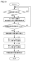
- FIG. 5 is a flow diagram for explaining the flow of processing executed in the control system shown in FIG. 4. The processing executed in the control system 101 will be explained with reference to FIG. 5.
- the following processing by the control system 101 is initiated a predetermined time (e.g., 30 minutes) after the automobile 200 has been loaded onto the automobile carrier 900.
- a predetermined time e.g., 30 minutes
- the following processing is executed a predetermined time after the housing 70 is attached to the bottom surface 200a of the automobile 200. More specifically, the following processing is executed a predetermined time after a switch (e.g., a power switch, or a switch that starts an operation) provided on the housing 70 is turned on by the user.
- a switch e.g., a power switch, or a switch that starts an operation
- the reason for delaying the processing for a predetermined time is as follows. Immediately after loading onto the car carrier 900 is complete, the battery 201 of the car 200 will have generated a considerable amount of heat due to the operation performed for loading. It is necessary to prevent the control system 101 from executing the following processing based on the surface temperature of the bottom surface 200a that has risen due to this heat generation. Therefore, the processing is delayed for a predetermined time as described above. Note that, from the viewpoint of preventing erroneous operation, it is preferable to position the above switch so that it does not protrude from the outer surface of the housing 70.
- step S1 the control device 30 determines whether a predetermined control period T has arrived. If it is determined that the control period T has arrived (YES in step S1), the control device 30 advances the process to step S2. If it is determined that the control period T has not arrived (NO in step S1), the control device 30 advances the process to step S1.
- step S2 the control device 30 acquires temperature information from the sensor 10 indicating the surface temperature of the bottom surface 200a of the automobile 200 detected by the sensor 10. After step S2, in step S3, the control device 30 determines whether the surface temperature of the bottom surface 200a of the automobile 200 is equal to or higher than a set temperature V1 as a first temperature.
- the control device 30 activates the alarm device 40 in step S4 to continuously emit sound and light (typically a flash). This alerts the surrounding area to the occurrence of an abnormality. After a certain time has elapsed since the alarm device 40 began to operate, the control device 30 activates the actuator 20 in step S5 to emit smoke.
- step S3 If it is determined that the surface temperature of the bottom surface 200a is lower than the set temperature V1 (NO in step S3), the control device 30 proceeds to step S1. Note that the control device 30 may execute the process of step S5 before the process of step S4. Alternatively, the control device 30 may execute the process of step S4 and the process of step S5 simultaneously.
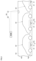
- FIG. 6 is a schematic diagram of the luggage compartment to explain the state in which the operating device shown in FIG. 4 is activated.
- the processing performed by the control system 101 and the processing performed by a fire warning system equipped with the control system 101 will be explained.
- smoke 800 is emitted from a smoke emitter included in the actuator 20, as shown in Figs. 4 and 6.
- the smoke 800 diffuses around the housing 70.
- the diffused smoke 800 is detected by a detector 301 installed on the ceiling 902a.
- the diffused smoke 800 is typically detected by a detector 301 installed on the ceiling 902a near the automobile 200 to which the control system 101 equipped with the activated actuator 20 is attached.
- the detector 301 When the detector 301 detects the smoke 800, the detector 301 is activated. When the detector 301 is activated, a signal P is transmitted from the activated detector 301 to the receiver 302. The receiver 302 receives the signal P and displays an alarm on the monitor 302a or generates an alarm on the speaker 302b. This allows the crew member CR1 positioned in the wheelhouse 901 to know that the battery 201 is in an abnormal temperature state. In other words, the crew member CR1 can know that there are signs of a fire in the battery 201.
- control system 101 makes it possible to activate the automatic fire alarm system 300 before the battery 201 ignites. This allows the crew members CR1, CR2, etc. to quickly take appropriate, pre-determined measures before the battery 201 ignites. As a result, the control system 101 makes it possible to reduce the risk of a fire caused by the automobile 200 in the luggage compartment 902.
- the control system 101 reports signs of a fire caused by the automobile 200 using the automatic fire alarm system 300, which is an existing facility on the car carrier 900. Therefore, the only work required to introduce the control system 101 is essentially to attach the control system 101 to the automobile 200.
- control system 101 makes it possible to reduce the risk of fire outbreaks by using existing automatic fire alarm equipment. Furthermore, the control system 101 can be easily introduced to the car carrier 900.
- smoke 800 is emitted by the actuator 20 from below the vehicle 200 equipped with the battery 201 that is in an abnormal temperature state.
- This allows the crew member CR2 positioned in the luggage compartment 902 to instantly identify the location of the vehicle 200 to which the control system 101 that emitted the smoke is attached by visually checking the emitted smoke.
- This allows the crew member CR2 and others to quickly take appropriate measures before the battery 201 ignites. This makes it possible to further reduce the risk of a fire caused by the vehicle 200 in the luggage compartment 902.
- the alarm device 40 continuously emits sound and light below the automobile 200 at the same time as the smoke 800 is emitted by the operating device 20. Therefore, the crew member CR2 can instantly identify the location of the automobile 200 by the sound and light emitted by the alarm device 40. This makes it possible to further reduce the risk of a fire caused by the automobile 200 in the luggage compartment 902.
- the position of the housing 70 can be changed as appropriate within the range in which the sensor 10 can detect the occurrence of an abnormality in the automobile 200.
- the housing 70 can be placed in contact with the bottom surface 200a of the automobile 200.
- the sensor 10 can be installed in a position where it can reliably detect an abnormality in the automobile 200. That is, according to this example, the position of the sensor 10 can be changed as appropriate so that the detection target (item that may cause a fire) is not located in the blind spot of the sensor 10. Therefore, according to this example, it is possible to prevent the sensor 10 from failing to detect the occurrence (manifestation) of an abnormality and the delay in discovering the abnormality due to the failure to detect it. According to this example, initial action can be taken quickly in response to an abnormality in the automobile 200.
- the control device 30 causes the operating device 20 to execute a process when the surface temperature of the bottom surface 200a of the automobile 200 detected by the sensor 10 becomes equal to or higher than the set temperature V1 (80°C in this example).
- the condition that the surface temperature must satisfy in order for the control device 30 to cause the operating device 20 to execute a process is not limited to this.
- the condition may be that the amount of change in the surface temperature per unit time is equal to or higher than a predetermined threshold value.
- control system 101 is configured to be capable of generating smoke from the operating device 20 at a stage before the battery 201 installed inside the automobile 200 ignites.
- control system 101 may also be configured to be capable of generating smoke from the operating device 20 at a stage immediately after the battery 201 ignites.
- control system 101 may be configured to be capable of generating smoke from the operating device 20 at a stage before a fire occurs inside an item that may ignite, and before the ignition causes combustion on the outer surface of the item. Even in this case, by employing the control system 101, the risk of fire can be reduced using existing automatic fire alarm equipment.
- control system 101 is used for a car carrier 900 in which a car 200 containing a battery 201 is placed in a cargo compartment 902 in which a detector 301 of an automatic fire alarm system 300 is installed.
- control system 101 can also be used in other cars besides a car carrier in which such a car is placed in the cargo compartment.
- control system 101 may be used in a cargo warehouse that is equipped with an automatic fire alarm detector and has a cargo room (space) in which a large-capacity battery system (item) such as a home storage battery is placed.
- a cargo room space
- a large-capacity battery system item
- control system 101 may be employed in an aircraft equipped with an automatic fire alarm detector and a luggage compartment (space) in which a container (item) containing a spray can or the like is placed.
- control system 101 may be employed in a freight train that includes a container (space) in which an automatic fire alarm detector is installed and in which a smartphone (item) containing a battery is placed.
- control system 101 may be employed in a ship or the like that is equipped with an automatic fire alarm detector and has a cargo hold (space) in which an unmanned or manned battery-powered drone (item) is placed.
- the items at risk of ignition may be various cargoes transported by ships, aircraft, or freight trains, or various cargoes placed in warehouses.
- items that may be ignited may not only be cargo, but also equipment (machinery) installed in a space where an automatic fire alarm detector is installed.
- items that may be ignited may be engines, generators, or purifiers installed in the engine room of a ship.
- ⁇ Modification> (First Modification) 7 is a schematic diagram of a luggage compartment for explaining a state in which the actuation device according to the first modification is activated.
- a control system 101A according to the first modification of the first embodiment will be described with reference to FIG.
- control system 101A As shown in FIG. 7, the control system 101A according to this modified example has a housing 70A instead of the housing 70.
- the control system 101A is different from the control system 101 in the arrangement of the housing 70A.
- the housing 70 is disposed in contact with a portion of the bottom surface 200a of the automobile 200 that is located near (more specifically, directly below) the battery 201 (see FIG. 2, etc.), whereas in the control system 101A, the housing 70A is disposed near the automobile 200 without contacting it. More specifically, in the control system 101A, the housing 70A is placed on a portion of the floor 902b of the luggage compartment 902 that faces the portion of the bottom surface 200a of the automobile 200 that is located directly below the battery 201.
- control system 101A makes it possible to reduce the risk of fire outbreaks using existing automatic fire alarm equipment.
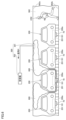
- Fig. 8 is a schematic diagram of a luggage compartment for explaining a state in which an operating device according to the second modification is activated.
- a control system 101B according to the second modification of the first embodiment will be described with reference to Fig. 8.
- the automatic fire alarm system 300 has multiple sensors 301A and a receiver 302. Specifically, the sensor 301A is provided in the luggage compartment 902 instead of the sensor 301.
- Detector 301A is an ultraviolet spot-type detector that detects the intensity of ultraviolet light and is activated when the change in the intensity of ultraviolet light is equal to or greater than a predetermined change amount W1.
- this modified example differs from the above configuration that uses detector 301 that detects smoke 800 in that it uses detector 301A that detects the intensity of ultraviolet light.
- the configuration of the actuator in control system 101B also differs from the configuration of actuator 20 in control system 101.
- the actuator 20 emits smoke 800 as a process for activating the detector 301 (see FIG. 6, etc.), while in the control system 101B according to this modified example, the actuator generates ultraviolet light as a process for activating the detector 301A.
- an ultraviolet LED (Light Emitting Diode) light that irradiates light containing ultraviolet light is used as the actuator.
- light containing ultraviolet light is irradiated from the ultraviolet LED light so that the change in the intensity of the ultraviolet light detected by the detector 301A is equal to or greater than the change W1, which is a second change amount determined in advance.
- ultraviolet light is emitted from the actuator by control device 30. Because ultraviolet light travels in a straight line, the emitted ultraviolet light repeatedly reflects off surrounding objects before entering the detection range of detector 301A. This causes the change in the intensity of the ultraviolet light detected by detector 301A to be equal to or greater than change W1. As a result, detector 301A can be activated. In this manner, in this modified example, detector 301A can be activated by the actuator even when no flame is generated.
- control system 101B makes it possible to reduce the risk of fire outbreaks using existing automatic fire alarm equipment.
- the control system 101B differs in the arrangement of the housing 70.
- the housing 70 is arranged so that a portion of the housing 70 protrudes outward from the periphery of the bottom surface 200a of the automobile 200. This allows the sensor 301A to more reliably detect ultraviolet light emitted from the operating device, compared to when the sensor 301A is arranged in contact with a portion of the bottom surface 200a located directly below the battery 201.
- Sensor 301A may be an infrared spot type sensor that detects the intensity of infrared light and is activated when the change in the infrared light intensity is equal to or greater than a second predetermined change amount W2.
- the activation device may be a device that emits infrared light instead of ultraviolet light. Specifically, an infrared LED light or a laser diode irradiates light that includes infrared light so that the change in the infrared light intensity detected by sensor 301A is equal to or greater than the predetermined change amount W2. Even with this configuration, the activation device can activate sensor 301A when no flame is generated.
- the heat from the battery 201 warms the air inside the automobile 200.
- the internal pressure of the automobile 200 rises.
- the sensor detects the rise in the internal pressure of the automobile 200, making it possible to detect abnormal heat generation from the battery 201.
- the control device judges whether the amount of pressure change in the internal pressure of the automobile 200 is equal to or greater than the amount of change W3, which is a predetermined first amount of change. If it is judged that the amount of pressure change in the internal pressure of the automobile 200 is equal to or greater than the amount of change W3, the control device activates the alarm device 40 to continuously emit sound and light, as in the above embodiment. Furthermore, the control device causes smoke to be emitted from the operating device 20 by activating the operating device 20 at the above-mentioned timing (a certain amount of time has elapsed since the alarm device 40 began to operate).
- control system of this modified example makes it possible to reduce the risk of fire outbreaks using existing automatic fire alarm equipment.
- the heat is transferred from the battery 201 to the body of the automobile 200, and the bottom surface 200a, which defines part of the body, is heated.
- the heating of the bottom surface 200a increases the intensity of infrared rays emitted from the bottom surface 200a.
- the sensor detects the intensity of the infrared rays, making it possible to detect abnormal heat generation in the battery 201.
- the control device judges whether the amount of change in the intensity of the infrared rays generated by the automobile 200 is equal to or greater than the amount of change W4, which is a predetermined first amount of change. If it is judged that the amount of change in the intensity of the infrared rays generated by the automobile 200 is equal to or greater than the amount of change W4, the control device activates the alarm device 40 to continuously generate sound and light, as in the above embodiment. Furthermore, the control device causes smoke to be emitted from the operating device 20 by activating the operating device 20 at the timing described above.
- control system of this modified example makes it possible to reduce the risk of fire outbreaks using existing automatic fire alarm equipment.
- a sensor that detects infrared rays has been described as an example. However, this is not limiting. A sensor that detects the intensity of ultraviolet rays generated from the automobile 200 may be used.
- the control device determines whether the amount of change in the intensity of ultraviolet rays generated from the automobile 200 is equal to or greater than a predetermined first amount of change W5. If it is determined that the amount of change in the intensity of ultraviolet rays generated from the automobile 200 is equal to or greater than the amount of change W5, the control device operates the alarm device 40 to continuously generate sound and light, as described above. Furthermore, the control device operates the operating device 20 at the timing described above, thereby causing smoke to be emitted from the operating device 20. Even with this configuration, effects similar to those described in the above embodiment can be obtained.
- a sensor that combines a part that detects infrared rays and a part that detects ultraviolet rays may be used. In this case, it becomes possible to detect the state of the automobile 200 while the two parts complement each other. This makes it possible to prevent the change in the state of the automobile 200 from being missed.
- the battery 201 When the battery 201 generates heat, the heat is transferred from the battery 201 to the body of the automobile 200, causing thermal distortion in the bottom surface 200a that defines part of the body.
- the sensor detects the distortion of the bottom surface 200a that increases due to heat generated by the battery 201, making it possible to detect abnormal heat generation in the battery 201.
- the control device judges whether the amount of change in distortion of the automobile 200 is equal to or greater than the amount of change W6, which is a predetermined first amount of change. If it is judged that the amount of change in distortion of the automobile 200 is equal to or greater than the amount of change W6, the control device activates the alarm device 40 to continuously emit sound and light, as in the above embodiment. Furthermore, the control device activates the operating device 20 at the above-mentioned timing, thereby causing smoke to be emitted from the operating device 20.
- control system of this modified example makes it possible to reduce the risk of fire outbreaks using existing automatic fire alarm equipment.
- the sensor in this modified example detects the appearance of the bottom surface 200a of the automobile 200 and the space around it as image data.
- a known camera can be used as a sensor with this configuration.
- the housing 70A is placed on the floor 902b of the luggage compartment 902, which faces the portion of the bottom surface 200a of the automobile 200 that is located directly below the battery 201.
- the control device in this modified example sets the presence of smoke in the image represented from the image data as a predetermined condition.
- the control device determines whether smoke is present in the image. If it is determined that smoke is present, the control device activates the alarm device 40 to continuously generate sound and light, as in the above embodiment. Furthermore, the control device causes smoke to be emitted from the operating device 20 by operating the operating device 20 at the timing described above.
- control system of this modified example makes it possible to reduce the risk of fire outbreaks using existing automatic fire alarm equipment.
- a sensor that detects the appearance of the bottom surface 200a of the automobile 200 and the space surrounding it as image data has been described as an example. However, this is not limited to this. For example, a sensor that detects the appearance of the top surface of the automobile 200 and the space surrounding it as image data may also be used.
- a sensor may be used that combines a portion that detects the exterior of the automobile 200 as image data as described above with a portion that detects infrared rays and/or a portion that detects ultraviolet rays. In this case, these portions complement each other to enable detection of the state of the automobile 200. This makes it possible to prevent missed detection of changes in the state of the automobile 200.
- Fig. 9 is a diagram for explaining the hardware configuration of each device constituting the control system according to the embodiment 2.
- Fig. 10 is a flow diagram for explaining the flow of processing executed in the control system shown in Fig. 9.
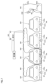
- Fig. 11 is a schematic diagram of a luggage compartment for explaining a state in which the operating device according to the embodiment is activated.
- control system 102 according to this embodiment, the fire warning system including the control system 102, and the control method will be described with reference to Figures 9 to 11.
- control system 102 is used instead of the control system 101.
- control system 101 of the first embodiment various devices are built into a single housing 70.
- devices are distributed and built into a first housing 71 and a second housing 72.
- the control system 102 is made up of two devices, a first device (first unit) and a second device (second unit).
- the control system 102 of the present embodiment differs from the control system 101 of the first embodiment.
- the senor 10, the control device 30, the alarm device 40, the power source 50, and the first interface 61 for communication are built into a first housing 71 having a substantially rectangular parallelepiped shape.
- the actuator 20, the power source 50A, and the second interface 62 for communication are built into a second housing 72 having a substantially rectangular parallelepiped shape.
- the first interface 61 and the second interface 62 are configured to be able to transmit and receive signals to each other via wireless communication.
- the power source 50A supplies power to the actuator 20 and the second interface 62. Note that communication between the first interface 61 and the second interface 62 is not limited to wireless communication and may be wired communication.
- the first housing 71 like the housing 70 of the first embodiment, is disposed in contact with a portion of the bottom surface 200a of the automobile 200 that is located near (more specifically, directly below) the battery 201.
- the second housing 72 is disposed around the detector 301. More specifically, the second housing 72 is placed on the floor 902b in a portion that is located below the detector 301.
- the process flow executed by the control system 102 differs from the process flow executed by the control system 101 of embodiment 1 (see FIG. 5) in that it includes steps S11 and S12 between steps S3 and S4.
- step S3 if it is determined in step S3 that the surface temperature is equal to or higher than the set temperature V1 (YES in step S3), the control device 30 activates the alarm device 40 in step S4 to continuously emit sound and light (typically, flashes). This alerts the surrounding area to the occurrence of an abnormality.
- step 11 the control device 30 transmits a control command Q to the actuator 20 via the first interface 61.
- step S12 the actuator 20 receives the control command Q via the second interface 62.
- step S5 the actuator 20 emits smoke 800 based on the fact that the actuator 20 has received the control command Q.
- the control device 30 operates the actuator 20 by a remote command to emit smoke 800 from the actuator 20 (more specifically, a smoke grenade).
- the process of step S4 may be executed simultaneously with the process of step S5, or may be executed after the process of step S5.
- control system 102 makes it possible to reduce the risk of fire outbreaks using existing automatic fire alarm equipment.
- the smoke 800 emitted by the actuator 20 is emitted below the detector 301. Therefore, by using the control system 102, the detector 301 can more reliably detect the smoke 800 emitted from the actuator 20.
- the first housing 71 is disposed in contact with the bottom surface 200a of the automobile 200, but the first housing 71 may be disposed in the vicinity of the automobile 200 without contacting it, as with the housing 70A in the control system 101A according to the first modified example of the first embodiment.
- the first housing 71 may be placed on the floor 902b of the luggage compartment 902, which faces the portion of the bottom surface 200a of the automobile 200 that is located directly below the battery 201.
- control device 30 is built into the first housing 71, but the control device 30 may be built into the second housing 72. That is, in the control system 102, the sensor 10, power supply 50, and first interface 61 may be built into the first housing 71, and the control device 30, actuator 20, power supply 50A, and second interface 62 may be built into the second housing 72.
- the sensor 10 transmits temperature information R indicating the surface temperature of the bottom surface 200a detected by the sensor 10 to the control device 30 via the first interface 61.
- the control device 30 receives the temperature information R via the second interface 62, and when it determines that the surface temperature indicated by the temperature information R is equal to or higher than the set temperature V1, it activates the actuator 20 to emit smoke 800. Even with this configuration, the same effect can be obtained as with a configuration in which the control device 30 is built into the first housing 71.
- Fig. 12 is a schematic diagram of an automobile to which a control system according to a first modification of this embodiment is applied, as viewed from the front side.
- Fig. 13 is a schematic front view of an actuating device according to this modification.
- Fig. 14 is a schematic bottom view of an actuating device according to this modification.
- a control system 102A according to a first modification of the second embodiment will be described with reference to Figs. 12 to 14.
- the control system 102A has a second housing 72A instead of the second housing 72.
- An actuator 20A is built into the second housing 72A instead of the actuator 20.
- the control device 30 is built into the first housing 71.
- the automatic fire alarm system 300 has multiple sensors 301B and a receiver 302. Specifically, a sensor 301B is provided in the luggage compartment 902 instead of the sensor 301.
- Sensor 301B is a so-called differential spot type sensor that is activated when the internal pressure of an air chamber provided in sensor 301B reaches or exceeds a set pressure.
- An air chamber is provided inside the differential spot type sensor.
- a diaphragm and contacts are provided in the air chamber.
- the diaphragm is deformed as the internal pressure of the air chamber rises. The deformation of the diaphragm closes the contacts. When the contacts are closed, sensor 301B is activated.
- this modified example differs from the configuration using the detector 301 for detecting smoke 800 described in the embodiment and the ultraviolet spot type or infrared spot type detector 301A described in the modified example of embodiment 1 in that it uses a differential spot type detector 301B.
- the configuration of actuator 20A and the arrangement of second housing 72A in control system 102A are different from the configuration of actuator 20 and the arrangement of second housing 72 in control system 102.
- the actuator 20 emits smoke 800 as a process for activating the detector 301 (see FIG. 11, etc.), whereas in the control system 102A according to this modification, the actuator 20A applies pressure from outside to the air chamber of the detector 301B as a process for activating the detector 301B.
- the actuator 20A has an actuator 21 configured to be capable of reciprocating motion in the vertical direction.
- the second housing 72A which houses the actuator 20A etc., has a gripping portion 72a consisting of a pair of arm-shaped parts.
- the gripping portion 72a grips the detector 301B. This causes the second housing 72A to be positioned in contact with the detector 301B.
- the actuator 20A drives the actuator 21 based on receiving a control command Q via the second interface 62.
- the actuator 21 presses the outer wall of the sensor 301B that defines the air chamber.
- the actuator 20A operates the actuator 21 so that the internal pressure of the air chamber becomes equal to or greater than the set pressure. This activates the sensor 301B. Even with this configuration, the actuator 20A can activate the sensor 301B even when no heat is being generated.
- control system 102A makes it possible to reduce the risk of fire outbreaks using existing automatic fire alarm equipment.
- the operating device 20A has the actuator 21
- the operating device 20A is not limited to having an actuator 21.
- the operating device 20A may have a servo motor and an elastic member such as a spring. In this case, the driving force of the servo motor can press the elastic member toward the outer wall of the sensor 301B.
- the operating device 20A may have a gas generator. In this case, the internal pressure of the air chamber can be increased by operating the gas generator directly below the sensor 301B.
- the operating device 20A may have explosives. In this case, the internal pressure of the air chamber can be increased by exploding the explosives directly below the sensor 301B.
- Fig. 15 is a schematic front view of an actuating device according to a second modification of the present embodiment.
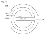
- Fig. 16 is a schematic bottom view of an actuating device according to this modification.
- the control system 102B according to this modification will be described with reference to Figs. 15 and 16.
- control system 102B has a second housing 72B instead of the second housing 72.
- An actuator 20B is built into the second housing 72B instead of the actuator 20.
- control device 30 is built into the first housing 71.
- the automatic fire alarm system 300 has multiple sensors 301C and a receiver 302. Specifically, a sensor 301C is provided in the luggage compartment 902 instead of the sensor 301.
- Sensor 301C is a constant temperature spot type detector that activates when the ambient temperature of sensor 301C reaches or exceeds a set temperature V2, which is the second temperature.
- Constant temperature spot type detectors have a heat receiving plate, a circular bimetal, and contacts. In sensor 301C, an increase in the temperature of the heat receiving plate causes the circular bimetal to distort or invert. Such distortion or inversion closes the contacts. When the contacts are closed, the sensor is activated.
- the configuration of actuator 20B and the arrangement of second housing 72B in control system 102B differ from the configuration of actuator 20 and the arrangement of second housing 72 in control system 102.
- the arrangement of second housing 72B is similar to that of second housing 72A in the first modified example of this embodiment, and therefore will not be described again.
- the actuator 20 emits smoke 800 as a process for activating the detector 301 (see FIG. 11, etc.), while in the control system 102B according to this modified example, the actuator 20B generates heat as a process for activating the detector 301C. More specifically, the actuator 20B has a nichrome wire 22. The actuator 20B heats the nichrome wire 22 to red heat, thereby generating enough heat to raise the ambient temperature of the detector 301C to the set temperature V2 or higher.
- the actuator 20B heats the nichrome wire 22 to red hot based on receiving the control command Q via the second interface 62.
- the ambient temperature of the detector 301C becomes equal to or higher than the set temperature V2 due to the red heat of the nichrome wire 22
- the temperature of the heat receiving plate rises.
- the circular bimetal is inverted, etc. This inversion activates the detector 301C.
- the actuator 20B can activate the detector 301C even when no heat is being generated by a flame.
- control system 102B makes it possible to reduce the risk of fire outbreaks using existing automatic fire alarm equipment.
- the actuator 20B has a nichrome wire 22, but the actuator 20B is not limited to having a nichrome wire 22.
- the actuator 20B may have a Peltier element or explosives.
- the Peltier element or explosives can generate heat to activate the sensor 301C.
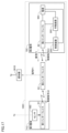
- FIG. 17 is a diagram for explaining the hardware configuration of each device that constitutes the control system 102C according to the third modification of this embodiment.
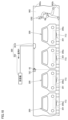
- FIG. 18 is a schematic diagram of a luggage compartment for explaining a state in which the operating device according to this modification is activated.
- the control system 102C according to the third modification of the second embodiment will be described with reference to these FIGS. 17 and 18.
- the control system 102C has a first housing 71C instead of the first housing 71.
- the first housing 71C contains a sensor 10C and a first interface 61.
- the first housing 71C, the sensor 10C, and the first interface 61 constitute an RFID (Radio Frequency Identification) tag equipped with a temperature sensor.
- RFID Radio Frequency Identification
- the sensor 10C corresponds to the part of the RFID tag that detects temperature.
- a contact temperature sensor is used as the sensor 10C.
- the first interface 61 corresponds to the part of the RFID tag that transmits temperature information detected by the sensor 10C as a signal via wireless communication, and receives a control command Q1 transmitted from the control device 30C (described below) via wireless communication.
- the first housing 71 corresponds to the protective member of the RFID tag that protects the sensor 10C and the first interface 61.
- the RFID tag configured in this manner is attached to the bottom surface 200a of the automobile 200. This allows the sensor 10C to detect the surface temperature of the bottom surface 200a. Note that multiple RFID tags may be attached to the bottom surface 200a as necessary.
- the RFID tag may be installed near the body of the automobile 200, or near the part where the battery 201 is mounted. When considering the ease of installation, it is more preferable that the RFID tag be installed on a lashing that fastens the floor 902b of the luggage compartment 902 to the automobile 200. In these cases, it is preferable to use, for example, a non-contact temperature sensor as the sensor 10C.
- the control system 102C has a second housing 72C instead of the second housing 72.
- the second housing 72C contains an actuator 20C, a control device 30C, a power source 50C, and a second interface 62.
- the second housing 72C is disposed adjacent to a third interface 63, which will be described later.
- the control system 102C further includes a third interface 63 for communication.
- the third interface 63 is a repeater that relays the transmission and reception of signals between the first interface 61 and the second interface 62, and relays the transmission of signals from the second interface 62 to the sensor 301D.
- the third interface 63 is installed, for example, on the ceiling 902a of the luggage compartment 902. Note that the location of the third interface 63 is not limited to this, and it may be installed on a wall of the luggage compartment 902, or on the floor 902b of the luggage compartment 902.
- the automatic fire alarm system 300 has multiple sensors 301D and a receiver 302. Specifically, the sensor 301D is provided in the luggage compartment 902 instead of the sensor 301.
- the sensor 301D is activated by receiving a predetermined signal. Due to the use of the sensor 301D configured in this manner, the configuration of the actuator 20C in the control system 102C differs from the configuration of the actuator 20 in the control system 102.
- the actuator 20 emits smoke 800 as a process for activating the detector 301 (see FIG. 11, etc.), whereas in the control system 102C according to this modification, the actuator 20C transmits a predetermined signal P1 to the detector 301D as a process for activating the detector 301D.
- a transmitter configured to transmit the signal P1 to the detector 301D by wireless communication or wired communication is used as the actuator 20C.
- the control device 30C acquires temperature information detected by the sensor 10C from the sensor 10C at a predetermined first period (e.g., every 30 seconds).
- a predetermined first period e.g., every 30 seconds.
- the control device 30C transmits a control command Q1 to the sensor 10C to change the first period to a shorter, predetermined second period (e.g., every 10 seconds).
- the control device 30C acquires temperature information detected by the sensor 10C from the sensor 10C at each second period.
- the set temperature V11 is set to a predetermined temperature lower than the set temperature V1 described above.
- the control device 30C causes the actuation device 20C to transmit a signal P1 to the detector 301D. This activates the detector 301D.
- control system 102C makes it possible to reduce the risk of fire outbreaks using existing automatic fire alarm equipment.
- control system 102 is configured so that, when the state of the automobile 200 detected by the sensor 10C satisfies a predetermined condition, the control device 30C can change the period for acquiring information from the sensor 10C from a first period to a shorter second period. This makes it possible to monitor the state of the automobile 200 more intensively in situations where the risk of fire is relatively high.
- control system 102C is described as having the third interface 63, but if direct communication is possible between the first interface 61 and the second interface 62, and if a signal can be sent directly from the second interface 62 to the sensor 301D, the control system 102C does not necessarily need to have the third interface 63.
- Fig. 19 is a diagram for explaining the hardware configuration of each device constituting the control system according to embodiment 3.
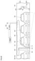
- Fig. 20 is a schematic diagram of a luggage compartment for explaining a state in which the operating device according to embodiment 3 is activated.
- control system 103 the fire warning system including the control system 103, and the control method will be described.
- the control system 103 is used instead of the control system 101.
- the sensor 13 is used instead of the sensor 10.
- the sensor 10 detects the state of one automobile 200.
- the sensor 13 is configured to detect the states of multiple automobiles 200.
- the control system 103 of the present embodiment differs from the control system 101 of the first embodiment.
- the housing 70 is disposed on a portion of the surface of a pillar 903 provided in the luggage compartment 902 that is located on the floor 902b side.
- the position of the housing 70 is not particularly limited to this, and it may be disposed on the surface of the wall of the luggage compartment 902, or on the floor 902b in a portion that faces the bottom surface 200a of a particular automobile 200.
- the sensor 13 built into the housing 70 is configured to be able to detect the state of multiple automobiles 200.
- a non-contact multi-eye sensor with a built-in non-contact temperature sensor is used as such a sensor 13.
- a non-contact multi-lens sensor is primarily composed of an array sensor (for example, a thermopile sensor) or a CMOS image sensor consisting of multiple non-contact temperature sensors, a lens, and a lens holder that holds the lens.
- a non-contact temperature sensor measures the temperature by measuring infrared rays emitted from an object.
- a non-contact multi-eye sensor that includes an array sensor consisting of a total of 64 non-contact temperature sensors arranged in 8 rows and 8 columns.
- the number and arrangement of the above sensors in the non-contact multi-eye sensor are not particularly limited to this, and can be changed as appropriate to suit conditions such as the desired viewing angle.
- the larger the viewing angle of the non-contact multi-eye sensor the wider the range of measurement that can be performed. Therefore, by selecting a sensor with a large viewing angle, it is expected that the number of automobiles 200 that can be monitored per installed unit will increase, and the monitoring area will be expanded.
- the surface temperature of the automobile 200 within the field of view corresponding to each of the multiple non-contact temperature sensors can be detected individually.
- the control device 30 acquires temperature information indicating the above-mentioned temperature detected by the sensor 13 from the sensor 13 at each predetermined control period T.
- the control device 30 causes the operating device 20 to execute a warning process when the temperatures of the multiple automobiles 200 detected by the sensor 13 satisfy a predetermined condition.
- control device 30 causes the operating device 20 to generate smoke when the number of surface temperatures that are equal to or higher than the set temperature V1 among the total of 64 points on the automobile 200 detected by the sensor 13 reaches or exceeds a predetermined number.
- control system 103 makes it possible to reduce the risk of fire outbreaks using existing automatic fire alarm equipment.
- control system 103 when the control system 103 is configured to detect the states of multiple automobiles 200 using the sensor 13 as described above, the work involved in installing the control system 103 can be reduced compared to when the state of only one automobile 200 is detected by the sensor.
- control device 30 generates smoke from the operating device 20 when the surface temperature of the automobile 200 detected by the sensor 13 becomes equal to or higher than the set temperature V1, but the present invention is not limited to this.
- control device 30 may generate smoke from the operating device 20 when the temperature difference between the surface temperature of the automobile 200 detected by the sensor 13 and the ambient temperature (more specifically, the ambient temperature of the luggage compartment 902 in which the automobile 200 is loaded) becomes equal to or exceeds a set temperature.
- each of the surface temperatures at 64 points on the automobile 200 detected by the sensor 13 may be compared with the above-mentioned ambient temperature, and smoke may be generated from the operating device 20 when the number of surface temperatures whose temperature difference with the above-mentioned ambient temperature is equal to or greater than a set temperature reaches or exceeds a predetermined number.
- the control system 103 must further include a temperature sensor for measuring the above-mentioned ambient temperature in addition to the sensor 13.
- the surface temperature of the automobile 200 may be compared with a predetermined temperature.
- control device 30 may cause the operating device 20 to generate smoke when the amount of change in the surface temperature of the automobile 200 detected by the sensor 13 exceeds a predetermined amount of change.
- the control device 30 acquires the surface temperatures of a total of 64 points of the automobile 200 detected by the sensor 13 at a certain point in time, and stores these.
- the certain point in time can be, for example, the point in time when a predetermined time (e.g., 30 minutes) has elapsed since the automobile 200 was completely loaded onto the automobile carrier 900.
- the control device 30 acquires temperature information from the sensor 13 indicating the surface temperatures of the automobile 200 at a total of 64 locations detected by the sensor 13 at each predetermined control period T. The control device 30 then calculates the amount of change in each of these surface temperatures from the surface temperatures of the automobile 200 at the above-mentioned certain point in time. If the number of the 64 amounts of change calculated in this way that are equal to or greater than a predetermined amount of change is equal to or greater than a predetermined number, smoke may be generated from the operating device 20.
Landscapes
- General Physics & Mathematics (AREA)
- Physics & Mathematics (AREA)
- Business, Economics & Management (AREA)
- Emergency Management (AREA)
- Chemical & Material Sciences (AREA)
- Engineering & Computer Science (AREA)
- Ocean & Marine Engineering (AREA)
- Combustion & Propulsion (AREA)
- Mechanical Engineering (AREA)
- Analytical Chemistry (AREA)
- Public Health (AREA)
- Health & Medical Sciences (AREA)
- Fire Alarms (AREA)
Abstract
Description
図1は、本実施の形態に係る制御システムと火災兆候報知システムとが採用された自動車運搬船の内部の機器配置を示す図である。図2は、本実施の形態に係る制御システムが取付けられた自動車を正面側から見た模式図である。図3は、本実施の形態に係る制御システムが取付けられた自動車を側面側から見た模式図である。まず、本実施の形態に係る制御システム101および火災兆候報知システムについて説明するに先立って、図1ないし図3を参照して、制御システム101が採用された自動車運搬船900の構成の概要について説明する。
(第1変形例)
図7は、第1変形例に係る作動装置が作動した状態を説明するための荷室の模式図である。以下、図7を参照して、実施の形態1の第1変形例に係る制御システム101Aについて説明する。
本変形例では、自動火災報知設備が、煙を感知する感知器301の代わりに、少なくとも、紫外線を感知するように構成された感知器を備える構成について説明する。図8は、第2変形例に係る作動装置が作動した状態を説明するための荷室の模式図である。以下、図8を参照して、実施の形態1の第2変形例に係る制御システム101Bについて説明する。
本変形例では、制御システムを構成するセンサが、自動車200の状態としての当該自動車200の温度を検知する代わりに、自動車200の内圧を検知する構成について説明する。このような構成の場合、当該センサとしては、公知の圧力センサが利用できる。
本変形例では、制御システムを構成するセンサが、自動車200の状態としての当該自動車200の温度を検知する代わりに、自動車200から発生する赤外線を検知する構成について説明する。このような構成の場合、当該センサとしては、公知の赤外線センサが利用できる。
本変形例では、制御システムを構成するセンサが、自動車200の状態としての当該自動車200の温度を検知する代わりに、自動車200の歪みを検知する構成について説明する。詳しくは、本変形例に係るセンサは、自動車200の底面200aの歪みを検知する。このような構成の場合、当該センサとしては、公知の歪みセンサが利用できる。
本変形例では、制御システムを構成するセンサが、自動車200の状態としての当該自動車200の温度を検知する代わりに、自動車200の外観を画像データとして検知する構成について説明する。ここで、自動車200の外観とは、自動車200自体の外観のみならず、自動車200およびその周囲の空間を含む外観も意味している。
図9は、実施の形態2に係る制御システムを構成する各機器のハードウェア構成を説明するための図である。図10は、図9に示す制御システムで実行される処理の流れを説明するためのフロー図である。図11は、本実施の形態に係る作動装置が作動した状態を説明するための荷室の模式図である。
(第1変形例)
本変形例では、自動火災報知設備300が、煙を感知する感知器301の代わりに、熱を感知するように構成された感知器301Bを備える構成について説明する。図12は、本実施の形態の第1変形例に係る制御システムが適用される自動車を正面側から見た模式図である。図13は、本変形例に係る作動装置の模式正面図である。図14は、本変形例に係る作動装置の模式底面図である。以下、これら図12ないし図14を参照して、実施の形態2の第1変形例に係る制御システム102Aについて説明する。
本変形例においても、自動火災報知設備300が、熱を感知するように構成された感知器を備える構成について説明する。図15は、本実施の形態の第2変形例に係る作動装置の模式正面図である。図16は、本変形例に係る作動装置の模式底面図である。以下、図15および図16を参照して、本変形例に係る制御システム102Bについて説明する。
本変形例では、自動火災報知設備300が、煙を感知する感知器301の代わりに、信号を検知するように構成された感知器301Dを備える構成について説明する。図17は、本実施の形態の第3変形例に係る制御システム102Cを構成する各機器のハードウェア構成を説明するための図である。図18は、本変形例に係る作動装置が作動した状態を説明するための荷室の模式図である。以下、これら図17および図18を参照して、実施の形態2の第3変形例に係る制御システム102Cについて説明する。
図19は、実施の形態3に係る制御システムを構成する各機器のハードウェア構成を説明するための図である。図20は、実施の形態3に係る作動装置が作動した状態を説明するための荷室の模式図である。
上述した本発明の実施の形態およびその変形例において示した各部の形状や構成、大きさ、数、材質等は、本発明の趣旨を逸脱しない限りにおいて種々変更が可能である。
Claims (10)
- 自動火災報知設備の感知器が設置された空間に前記感知器とは別体として配置され、かつ、発火の虞のある物品の状態を検知するセンサと、
前記感知器を作動させるための処理を実行する作動装置と、
前記センサによって検知される前記物品の状態が予め定められた条件を満たす場合に、前記作動装置に前記処理を実行させる制御装置とを備え、
前記物品の状態は、前記物品の温度、前記物品の内圧の圧力変化、前記物品から発生する赤外線の強度変化、前記物品から発生する紫外線の強度変化、および、前記物品の歪みのうちの少なくともいずれかである、制御システム。 - 前記物品の状態が前記物品の温度である場合には、前記条件は、予め定められた第1温度以上となることであり、
前記物品の状態が、前記物品の内圧の圧力変化、前記物品から発生する紫外線の強度変化、前記物品から発生する赤外線の強度変化、および、前記物品の歪み変化のうちのいずれかである場合には、前記条件は、予め定められた第1変化量以上となることである、請求項1に記載の制御システム。 - 前記感知器は、煙を感知した場合に作動するものであり、
前記作動装置は、前記処理として煙を発生させる、請求項1または2に記載の制御システム。 - 前記感知器は、紫外線および赤外線のうちのいずれか一方の光を感知し、かつ、前記一方の光の強度の変化量が予め定められた第2変化量以上となる場合に作動するものであり、
前記作動装置は、前記処理として前記一方の光を発生させることにより、前記感知器で感知される前記一方の光の変化量を前記第2変化量以上とする、請求項1または2に記載の制御システム。 - 前記感知器は、当該感知器の内部圧力が予め定められた圧力以上となると作動する第1の構成、または、当該感知器の周囲温度が予め定められた第2温度以上となると作動する第2の構成であり、
前記感知器が前記第1の構成である場合には、前記作動装置は、前記処理として、前記感知器に外部から圧力を加えることによって前記内部圧力を前記予め定められた圧力以上に上昇させ、
前記感知器が前記第2の構成である場合には、前記作動装置は、前記処理として熱を発生させることにより、前記感知器の周囲温度を前記第2温度以上とする、請求項1または2に記載の制御システム。 - 前記物品は、貨物であり、
前記空間は、荷室である、請求項1に記載の制御システム。 - 前記貨物は、バッテリを内部に含む自動車であり、
前記荷室は、自動車運搬船内に設けられたものである、請求項6に記載の制御システム。 - 前記センサは、前記バッテリの近傍に位置する部分の前記自動車の表面温度を検知する、請求項7に記載の制御システム。
- 前記センサと、前記作動装置と、前記制御装置とを内蔵する筐体をさらに備え、
前記筐体は、前記物品に当接して配置されるかあるいは前記物品の近傍に配置される、請求項1に記載の制御システム。 - 前記センサと通信用の第1インターフェイスとを内蔵し、かつ、前記物品に当接して配置されるかあるいは前記物品の近傍に配置された第1筐体と、
前記作動装置と通信用の第2インターフェイスとを内蔵し、かつ、前記感知器に当接して配置されるかあるいは前記感知器の周辺に配置された第2筐体とをさらに備え、
前記制御装置は、前記第1筐体および前記第2筐体のうちのいずれか一方に内蔵され、
前記制御装置が前記第1筐体に内蔵されている場合には、
前記制御装置は、前記センサによって検知される前記物品の状態が前記条件を満たすと、前記第1インターフェイスを介して、予め定められた指令を前記作動装置宛てに送信し、
前記作動装置は、前記第2インターフェイスを介して前記指令を受信したことに基づき、前記処理を実行し、
前記制御装置が前記第2筐体に内蔵されている場合には、
前記センサは、当該センサによって検知される前記物品の状態を示す情報を、前記第1インターフェイスを介して、前記制御装置宛てに送信し、
前記制御装置は、前記第2インターフェイスを介して前記情報を受信し、かつ、前記情報が示す前記物品の状態が前記条件を満たすと、前記作動装置に前記処理を実行させる、請求項1に記載の制御システム。
Priority Applications (3)
| Application Number | Priority Date | Filing Date | Title |
|---|---|---|---|
| KR1020257032671A KR20250154497A (ko) | 2023-03-14 | 2024-03-13 | 제어 시스템 |
| JP2025506898A JPWO2024190821A1 (ja) | 2023-03-14 | 2024-03-13 | |
| CN202480018485.9A CN120883259A (zh) | 2023-03-14 | 2024-03-13 | 控制系统 |
Applications Claiming Priority (2)
| Application Number | Priority Date | Filing Date | Title |
|---|---|---|---|
| JP2023-039675 | 2023-03-14 | ||
| JP2023039675 | 2023-03-14 |
Publications (1)
| Publication Number | Publication Date |
|---|---|
| WO2024190821A1 true WO2024190821A1 (ja) | 2024-09-19 |
Family
ID=92755263
Family Applications (1)
| Application Number | Title | Priority Date | Filing Date |
|---|---|---|---|
| PCT/JP2024/009761 Ceased WO2024190821A1 (ja) | 2023-03-14 | 2024-03-13 | 制御システム |
Country Status (4)
| Country | Link |
|---|---|
| JP (1) | JPWO2024190821A1 (ja) |
| KR (1) | KR20250154497A (ja) |
| CN (1) | CN120883259A (ja) |
| WO (1) | WO2024190821A1 (ja) |
Citations (3)
| Publication number | Priority date | Publication date | Assignee | Title |
|---|---|---|---|---|
| JP2005312642A (ja) * | 2004-04-28 | 2005-11-10 | Horiba Ltd | 自動車運搬船の火災検知通報システム |
| JP2010160767A (ja) * | 2009-01-09 | 2010-07-22 | Hochiki Corp | 煙感知器の試験設備及びそのための装置 |
| CN112886083A (zh) * | 2021-02-04 | 2021-06-01 | 昆明理工大学 | 一种储能系统锂离子电池火灾预警方法 |
-
2024
- 2024-03-13 CN CN202480018485.9A patent/CN120883259A/zh active Pending
- 2024-03-13 JP JP2025506898A patent/JPWO2024190821A1/ja active Pending
- 2024-03-13 WO PCT/JP2024/009761 patent/WO2024190821A1/ja not_active Ceased
- 2024-03-13 KR KR1020257032671A patent/KR20250154497A/ko active Pending
Patent Citations (3)
| Publication number | Priority date | Publication date | Assignee | Title |
|---|---|---|---|---|
| JP2005312642A (ja) * | 2004-04-28 | 2005-11-10 | Horiba Ltd | 自動車運搬船の火災検知通報システム |
| JP2010160767A (ja) * | 2009-01-09 | 2010-07-22 | Hochiki Corp | 煙感知器の試験設備及びそのための装置 |
| CN112886083A (zh) * | 2021-02-04 | 2021-06-01 | 昆明理工大学 | 一种储能系统锂离子电池火灾预警方法 |
Also Published As
| Publication number | Publication date |
|---|---|
| JPWO2024190821A1 (ja) | 2024-09-19 |
| CN120883259A (zh) | 2025-10-31 |
| KR20250154497A (ko) | 2025-10-28 |
Similar Documents
| Publication | Publication Date | Title |
|---|---|---|
| US11385213B2 (en) | Storage bin volume sensor with VOC sensing safety feature | |
| AU2002341771B2 (en) | Fire suppression system and solid propellant aerosol generator for use therein | |
| US20010054964A1 (en) | Fire suppression and indicator system and fire detection device | |
| US20190334146A1 (en) | Protection device for battery, battery, battery pack, and vehicle | |
| US9573005B2 (en) | Protection device | |
| EP2856046B1 (en) | Automatic shutdown systems for refrigerated cargo containers | |
| US20030058114A1 (en) | Fire detection system | |
| CA2844548C (en) | Fire detection system | |
| AU2020357635B2 (en) | Monitoring apparatus for a motor vehicle, warning device for a vehicle, warning system and method for operating a monitoring apparatus | |
| CN113521605B (zh) | 一种电池仓储自动灭火装置及系统 | |
| AU2002341771A1 (en) | Fire suppression system and solid propellant aerosol generator for use therein | |
| CN211752025U (zh) | 仓储机器人 | |
| KR20250154497A (ko) | 제어 시스템 | |
| KR20140049622A (ko) | 차량 전소 방지 시스템 및 방법 | |
| JPH07227437A (ja) | 車両用自動消火装置 | |
| CA2568325C (en) | Smoke warning system | |
| CN115909635A (zh) | 一种集装箱船货物失火探测报警系统及集装箱船 | |
| KR101984539B1 (ko) | Iot 센서와 영상 신호처리 기반의 특수 선박용 진동, 화재, 연기 위험상황 감지 및 통보시스템 | |
| JP2026054033A (ja) | 制御システム | |
| JPH07160971A (ja) | 異常警報装置 | |
| JP5444266B2 (ja) | 車輪状態監視装置 | |
| KR102842174B1 (ko) | 차량 운반선 내 차량의 화재감지 및 초기 대응을 위한 자율이동로봇 시스템 및 이의 방법 | |
| FR2811117A1 (fr) | Dispositif d'identification a distance de la presence d'un materiau ou produit | |
| KR102900815B1 (ko) | 발화 방지 및 발화 감지를 모니터링 하는 배터리 이송 용기 및 이를 수행하는 시스템 | |
| Kulkarni et al. | Development of sensor and optimal placement for smoke detection in an electric vehicle battery pack |
Legal Events
| Date | Code | Title | Description |
|---|---|---|---|
| 121 | Ep: the epo has been informed by wipo that ep was designated in this application |
Ref document number: 24770926 Country of ref document: EP Kind code of ref document: A1 |
|
| ENP | Entry into the national phase |
Ref document number: 2025506898 Country of ref document: JP Kind code of ref document: A |
|
| WWE | Wipo information: entry into national phase |
Ref document number: 2025506898 Country of ref document: JP |
|
| WWE | Wipo information: entry into national phase |
Ref document number: 202480018485.9 Country of ref document: CN |
|
| ENP | Entry into the national phase |
Ref document number: 1020257032671 Country of ref document: KR Free format text: ST27 STATUS EVENT CODE: A-0-1-A10-A15-NAP-PA0105 (AS PROVIDED BY THE NATIONAL OFFICE) |
|
| WWE | Wipo information: entry into national phase |
Ref document number: KR1020257032671 Country of ref document: KR |
|
| NENP | Non-entry into the national phase |
Ref country code: DE |
|
| WWP | Wipo information: published in national office |
Ref document number: 1020257032671 Country of ref document: KR |
|
| WWP | Wipo information: published in national office |
Ref document number: 202480018485.9 Country of ref document: CN |
|
| 122 | Ep: pct application non-entry in european phase |
Ref document number: 24770926 Country of ref document: EP Kind code of ref document: A1 |