WO2024190424A1 - 電源モジュール - Google Patents
電源モジュール Download PDFInfo
- Publication number
- WO2024190424A1 WO2024190424A1 PCT/JP2024/007393 JP2024007393W WO2024190424A1 WO 2024190424 A1 WO2024190424 A1 WO 2024190424A1 JP 2024007393 W JP2024007393 W JP 2024007393W WO 2024190424 A1 WO2024190424 A1 WO 2024190424A1
- Authority
- WO
- WIPO (PCT)
- Prior art keywords
- heat
- power supply
- supply module
- cooling
- case
- Prior art date
- Legal status (The legal status is an assumption and is not a legal conclusion. Google has not performed a legal analysis and makes no representation as to the accuracy of the status listed.)
- Ceased
Links
Images
Classifications
-
- H—ELECTRICITY
- H05—ELECTRIC TECHNIQUES NOT OTHERWISE PROVIDED FOR
- H05K—PRINTED CIRCUITS; CASINGS OR CONSTRUCTIONAL DETAILS OF ELECTRIC APPARATUS; MANUFACTURE OF ASSEMBLAGES OF ELECTRICAL COMPONENTS
- H05K7/00—Constructional details common to different types of electric apparatus
- H05K7/20—Modifications to facilitate cooling, ventilating, or heating
- H05K7/2089—Modifications to facilitate cooling, ventilating, or heating for power electronics, e.g. for inverters for controlling motor
- H05K7/20945—Thermal management, e.g. inverter temperature control
-
- H—ELECTRICITY
- H05—ELECTRIC TECHNIQUES NOT OTHERWISE PROVIDED FOR
- H05K—PRINTED CIRCUITS; CASINGS OR CONSTRUCTIONAL DETAILS OF ELECTRIC APPARATUS; MANUFACTURE OF ASSEMBLAGES OF ELECTRICAL COMPONENTS
- H05K7/00—Constructional details common to different types of electric apparatus
- H05K7/20—Modifications to facilitate cooling, ventilating, or heating
- H05K7/2089—Modifications to facilitate cooling, ventilating, or heating for power electronics, e.g. for inverters for controlling motor
- H05K7/20927—Liquid coolant without phase change
-
- B—PERFORMING OPERATIONS; TRANSPORTING
- B60—VEHICLES IN GENERAL
- B60L—PROPULSION OF ELECTRICALLY-PROPELLED VEHICLES; SUPPLYING ELECTRIC POWER FOR AUXILIARY EQUIPMENT OF ELECTRICALLY-PROPELLED VEHICLES; ELECTRODYNAMIC BRAKE SYSTEMS FOR VEHICLES IN GENERAL; MAGNETIC SUSPENSION OR LEVITATION FOR VEHICLES; MONITORING OPERATING VARIABLES OF ELECTRICALLY-PROPELLED VEHICLES; ELECTRIC SAFETY DEVICES FOR ELECTRICALLY-PROPELLED VEHICLES
- B60L53/00—Methods of charging batteries, specially adapted for electric vehicles; Charging stations or on-board charging equipment therefor; Exchange of energy storage elements in electric vehicles
- B60L53/20—Methods of charging batteries, specially adapted for electric vehicles; Charging stations or on-board charging equipment therefor; Exchange of energy storage elements in electric vehicles characterised by converters located in the vehicle
- B60L53/22—Constructional details or arrangements of charging converters specially adapted for charging electric vehicles
-
- H—ELECTRICITY
- H05—ELECTRIC TECHNIQUES NOT OTHERWISE PROVIDED FOR
- H05K—PRINTED CIRCUITS; CASINGS OR CONSTRUCTIONAL DETAILS OF ELECTRIC APPARATUS; MANUFACTURE OF ASSEMBLAGES OF ELECTRICAL COMPONENTS
- H05K7/00—Constructional details common to different types of electric apparatus
- H05K7/20—Modifications to facilitate cooling, ventilating, or heating
- H05K7/20845—Modifications to facilitate cooling, ventilating, or heating for automotive electronic casings
- H05K7/20872—Liquid coolant without phase change
-
- H—ELECTRICITY
- H05—ELECTRIC TECHNIQUES NOT OTHERWISE PROVIDED FOR
- H05K—PRINTED CIRCUITS; CASINGS OR CONSTRUCTIONAL DETAILS OF ELECTRIC APPARATUS; MANUFACTURE OF ASSEMBLAGES OF ELECTRICAL COMPONENTS
- H05K7/00—Constructional details common to different types of electric apparatus
- H05K7/20—Modifications to facilitate cooling, ventilating, or heating
- H05K7/2089—Modifications to facilitate cooling, ventilating, or heating for power electronics, e.g. for inverters for controlling motor
- H05K7/20936—Liquid coolant with phase change
-
- B—PERFORMING OPERATIONS; TRANSPORTING
- B60—VEHICLES IN GENERAL
- B60L—PROPULSION OF ELECTRICALLY-PROPELLED VEHICLES; SUPPLYING ELECTRIC POWER FOR AUXILIARY EQUIPMENT OF ELECTRICALLY-PROPELLED VEHICLES; ELECTRODYNAMIC BRAKE SYSTEMS FOR VEHICLES IN GENERAL; MAGNETIC SUSPENSION OR LEVITATION FOR VEHICLES; MONITORING OPERATING VARIABLES OF ELECTRICALLY-PROPELLED VEHICLES; ELECTRIC SAFETY DEVICES FOR ELECTRICALLY-PROPELLED VEHICLES
- B60L2210/00—Converter types
- B60L2210/30—AC to DC converters
-
- B—PERFORMING OPERATIONS; TRANSPORTING
- B60—VEHICLES IN GENERAL
- B60L—PROPULSION OF ELECTRICALLY-PROPELLED VEHICLES; SUPPLYING ELECTRIC POWER FOR AUXILIARY EQUIPMENT OF ELECTRICALLY-PROPELLED VEHICLES; ELECTRODYNAMIC BRAKE SYSTEMS FOR VEHICLES IN GENERAL; MAGNETIC SUSPENSION OR LEVITATION FOR VEHICLES; MONITORING OPERATING VARIABLES OF ELECTRICALLY-PROPELLED VEHICLES; ELECTRIC SAFETY DEVICES FOR ELECTRICALLY-PROPELLED VEHICLES
- B60L2270/00—Problem solutions or means not otherwise provided for
- B60L2270/46—Heat pumps, e.g. for cabin heating
Definitions
- This disclosure relates to a power supply module.
- the power supply module described in Patent Document 1 has a cooling flow path formed by a metallic cooling partition and partition cover disposed inside the case body, and a cooling fluid flows through the cooling flow path.
- the inside of the case body is divided into two spaces by the cooling flow path, with the electronic circuitry housed in the space on the upper case side and the control board housed in the space on the lower case side.
- the electronic circuit such as the converter circuit described in Patent Document 1 has multiple electronic components with different heat generation amounts, such as a capacitor, a reactor, a transformer, a high-voltage switching element, and a low-voltage switching element, which are arranged so as to be in thermal contact with the cooling partition and the partition cover.
- the cooling fluid absorbs heat generated by the multiple electronic components and suppresses the temperature rise of the electronic components.
- a part of the heat absorbed by the cooling fluid is dissipated from the surfaces of the metallic cooling partition and the partition cover to the internal space of the case body.
- the cooling partition and the partition cover of the power supply module described in Patent Document 1 are entirely made of metal, they have a high heat absorption efficiency for absorbing heat generated by the electronic components, while also having a high heat dissipation efficiency for dissipating the absorbed heat to the outside, so there was room for improvement in terms of using the heat absorbed by the cooling fluid for purposes such as heating the vehicle interior.
- the power supply module has a cooling case in which a plurality of electronic components with different heat generation are opposed and a cooling fluid flows through a flow path formed inside, and the cooling case has a first portion opposed to the electronic components with a relatively large amount of heat generation, and a second portion opposed to the electronic components with a relatively small amount of heat generation and having a lower thermal conductivity than the first portion.
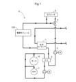
- FIG. 1 is a circuit configuration diagram of a cooling system including a power supply module according to a first embodiment.
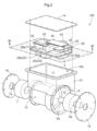
- FIG. 2 is an exploded perspective view of the power supply module.
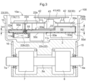
- FIG. 2 is a vertical cross-sectional view of the power supply module.
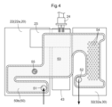
- 4 is a cross-sectional view taken along line IV-IV in FIG. 2.
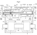
- FIG. 11 is a vertical cross-sectional view of a power supply module according to a second embodiment.
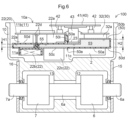
- FIG. 11 is a vertical cross-sectional view of a power supply module according to a third embodiment.
- the cooling circuit A including the power supply module 100 cools the power supply module 100 with a cooling fluid.
- the cooling fluid is a cooling water such as long-life coolant (LLC), an insulating oil such as paraffin, or a refrigerant such as hydrofluorocarbon (HFC) or hydrofluoroolefin (HFO).
- LLC long-life coolant
- HFC hydrofluorocarbon
- HFO hydrofluoroolefin
- a liquid with high electrical insulation such as a cooling water such as long-life coolant (LLC) or a fluorine-based inert liquid
- a cooling liquid composed of a cooling water or insulating oil may also be used.
- the cooling circuit A is mounted on a vehicle that charges a battery (not shown) with external power.
- the power supply module 100 is configured by accommodating at least an OBC (On Board Charger) board 20 (an example of a drive board), a motor drive board 30 (an example of a drive board), and a control board 40 for controlling the OBC board 20 and the motor drive board 30 in a housing 10.
- the power supply module 100 has a first space 11.
- the OBC board 20, the motor drive board 30, and the control board 40 are separate boards, and are accommodated in the first space 11 in a parallel orientation.
- FIG. 3 shows a cross section cut in a direction perpendicular to the plate surface of the OBC board 20 (the motor drive board 30, the control board 40).
- the direction perpendicular to the plate surface of the OBC board 20 is referred to as the "vertical direction”.
- the direction in which the control board 40 is viewed from the OBC board 20 and motor drive board 30 along the vertical direction will be referred to as the "upper direction", “upper side”, etc.
- the direction in which the OBC board 20 and motor drive board 30 are viewed from the control board 40 will be referred to as the "lower direction", "lower side", etc.
- the housing 10 has a first space 11 and a second space 12 and a third space 13 separated from each other.
- the second space 12 and the third space 13 are located below the first space 11.
- the second space 12 houses a motor 6 driven by a motor drive board 30, and the third space 13 houses a gear mechanism 7 that reduces the rotation of the motor 6 and outputs it.
- the housing 10 has an opening 10a above the first space 11, and the OBC board 20, the motor drive board 30, the control board 40, and the cooling case 50 are housed in the first space 11 through the opening 10a.
- the opening 10a is closed by a lid 14 (see Figure 2), and the first space 11 is a closed space.
- the second space 12 houses the motor 6 from the side, and is closed by a motor cover 15 fastened with a bolt (not shown) to form a closed space.
- Motor shafts 6a extend from the motor 6 on both sides along the rotation axis, and one of the motor shafts 6a penetrates the motor cover 15 and is exposed to the outside of the housing 10.
- the other motor shaft 6a penetrates to the third space 13.
- the third space 13 houses the gear mechanism 7 from the side and is closed by a gear cover 16 fastened with a bolt (not shown) to form a closed space.
- the other motor shaft 6a extending from the second space 12 is connected to the gear mechanism 7, and the rotation of the motor 6 is input via the motor shaft 6a.
- the gear mechanism 7 decelerates the rotation of the motor 6 and outputs it from the gear shaft 7a.
- the gear shaft 7a penetrates the gear cover 16 and is exposed to the outside of the housing 10.
- the OBC board 20 is equipped with a power converter 22 (an example of an electronic circuit).
- the power converter 22 includes at least an AC-DC converter that converts externally input AC to DC, and a DC-DC converter that converts DC voltage into a DC voltage suitable for charging a battery (not shown).
- the configurations of the AC-DC converter and DC-DC converter are publicly known, so a detailed description will be omitted.
- the AC-DC converter and DC-DC converter of the power converter 22 include a heat-generating component 22a (an example of an electronic component), which is an example of an electronic component that generates a relatively small amount of heat, and a reactor 22b (an example of an electronic component) and a transformer 22c (an example of an electronic component), which are examples of electronic components that generate a relatively large amount of heat.
- a heat-generating component 22a include a diode (an example of an electronic component) and a switching element (an example of an electronic component).
- the motor drive board 30 is equipped with a power converter 32 (an example of an electronic circuit).
- the power converter 32 includes at least an inverter that controls the drive current that drives the motor 6.
- the configuration of the inverter is publicly known, so a detailed description is omitted.
- the control board 40 is equipped with a control circuit 41 that controls the power converter 22 and the power converter 32.
- the inverter of the power converter 32 includes heat-generating components 32a (an example of an electronic component that generates a relatively large amount of heat).
- heat-generating components 32a included in the power converter 32 include diodes (an example of an electronic component) and switching elements (an example of an electronic component). These electronic components have different heights.
- the OBC board 20 and the motor drive board 30 are located at the same height in the vertical direction.
- the control board 40 is arranged so as to overlap the OBC board 20 and the motor drive board 30 when viewed vertically (vertical view).
- Board-to-board connectors 42 are used to connect the OBC board 20 and the control board 40 and the motor drive board 30 and the control board 40.
- the OBC board 20 and the motor drive board 30 are located at the same height in the vertical direction, so that the OBC board 20 and the control board 40 and the motor drive board 30 and the control board 40 can be connected using two board-to-board connectors 42 of the same type. This configuration makes it easy to assemble the control board 40 to the OBC board 20 and the motor drive board 30, and also makes it easy to assemble because there is no need to use different types of connectors.
- the OBC substrate 20 and the motor drive substrate 30 are separate substrates.
- a film capacitor 43 (an example of an electronic component that generates a relatively large amount of heat) is disposed between the OBC substrate 20 and the motor drive substrate 30.
- the film capacitor 43 is used both for smoothing the inverter of the power converter 32 and for smoothing the secondary side of the DC-DC converter of the power converter 22.
- the film capacitor 43 serves two different smoothing purposes.
- the film capacitor 43 has a height in the vertical direction that extends from near the upper case 50b of the cooling case 50 to near the control board 40. That is, the vertical height of the film capacitor 43 is greater than the vertical height of the electronic components including the heat-generating component 22a mounted on the OBC board 20 and the electronic components including the heat-generating component 32a mounted on the motor drive board 30. Therefore, the periphery of the motor drive board 30 is surrounded by the walls of the control board 40, the film capacitor 43, and the housing 10, and is separated from the periphery of the OBC board 20. Therefore, it is possible to prevent the heat generated in the power converter 32 of the motor drive board 30 from being transferred to the OBC board 20 side.
- the first space 11 of the housing 10 accommodates a cooling case 50 for cooling the heat generating components 22a, reactor 22b, transformer 22c, and heat generating components 32a of the power converter 32.
- the cooling case 50 according to the present embodiment is configured as an insert molded product in which a material containing a metal with high thermal conductivity, such as aluminum, is insert molded into a material containing a resin with a lower thermal conductivity than the metal.
- the portion of the cooling case 50 made of a material containing a metal is referred to as the first portion 50c
- the portion made of a material containing a resin is referred to as the second portion 50d.
- the first portion 50c has a higher thermal conductivity, a higher heat absorption efficiency, and a higher heat dissipation efficiency than the second portion 50d.
- the boundary between the first portion 50c and the second portion 50d is a joint portion 50e.
- the cooling case 50 is integrally formed by joining a plate-shaped lower case 50a and an upper case 50b.
- the lower case 50a and the upper case 50b are both insert molded products, and each has a first portion 50c and a second portion 50d.
- the cooling case 50 has a space formed therein (between the lower case 50a and the upper case 50b), and a cooling fluid flows through the internal space.
- the OBC substrate 20 and the motor drive substrate 30 are located at the same height in the vertical direction.
- the power supply module 100 of this embodiment is equipped with a height adjustment mechanism. Specifically, the vertical flow path height H1 at the location facing the OBC substrate 20 (the location overlapping with the OBC substrate 20 when viewed vertically) is made different from the vertical flow path height H2 at the location facing the motor drive substrate 30 (the location overlapping with the motor drive substrate 30 when viewed vertically).
- the flow path height H2 is greater than the flow path height H1.
- the height adjustment mechanism of this embodiment makes the flow path heights H1 and H2 of the cooling case 50 different depending on the opposing substrate.
- the lower case 50a and the upper case 50b that constitute the cooling case 50 have a flat shape, but the upper case 50b has different heights at the portion corresponding to the OBC board 20 and the portion corresponding to the motor drive board 30. Specifically, the height of the portion of the upper case 50b that corresponds to the motor drive board 30 is higher than the height of the portion corresponding to the OBC board 20 relative to the lower case 50a.
- the heat generating component 22a used in the power converter 22 of the OBC board 20 and the heat generating component 32a used in the power converter 32 of the motor drive board 30 are both cooled by being abutted against the upper case 50b of the cooling case 50.
- the heat generating component 22a of the power converter 22 has a high mounting height
- the heat generating component 32a of the power converter 32 of the motor drive board 30 has a low mounting height.
- the flow path height H2 is made higher than the flow path height H1 by an amount equivalent to the difference between the mounting height of the heat generating component 22a and the mounting height of the heat generating component 32a. This allows the vertical heights of the OBC board 20 and the motor drive board 30 to be aligned with each other when both the tall heat generating component 22a and the short heat generating component 32a are in contact with the upper case 50b.
- the flow paths 53 of the cooling case 50 are arranged as shown in FIG. 4 when viewed in the vertical direction.
- the cooling fluid flows in from the inlet 51 of the cooling fluid in the cooling case 50 and flows out from the outlet 52.
- a plurality of protrusions 54 are formed in the flow path 53 on the downstream side facing the heat-generating component 32a.
- the protrusions 54 are formed on at least one of the upper case 50b and the lower case 50a so as to protrude from the outside toward the inside so as to hinder the flow of the cooling fluid.
- the protrusions 54 have a spherical notch shape and are arranged in a staggered pattern with respect to the flow direction of the cooling fluid.
- the protrusions 54 when the protrusions 54 are arranged on the lower case 50a, the protrusions 54 lift the water on the side closer to the lower case 50a to the side of the upper case 50b, generating a vortex. As a result, the cooling fluid on the side closer to the upper case 50b and the cooling fluid on the side closer to the lower case 50a mix together, and the water temperature on the side closer to the upper case 50b can be lowered.
- the cooling fluid closer to the upper case 50b where the water temperature has dropped, can absorb more heat, further reducing the temperature of the heat-generating component 32a.
- a metal base board 23 (an example of a drive board) is disposed in the upper case 50b.
- a film capacitor 43 and a connection terminal 24 to which a DC voltage is input from a battery (not shown) are attached to the metal base board 23.
- the first portion 50c is provided at a location where the reactor 22b, transformer 22c, heat generating component 32a, and film capacitor 43, which generate relatively large amounts of heat, are in contact
- the second portion 50d is provided at other locations including a location where the heat generating component 22a, which generates relatively small amounts of heat, is in contact.
- the film capacitor 43 is mounted so as to be in contact with the first portion 50c via the metal base substrate 23, but the metal base substrate 23 has the same thermal conductivity as the first portion 50c. Therefore, the film capacitor 43 can be considered to be in substantial contact with the first portion 50c.
- the reactor 22b, the transformer 22c, the heat generating component 32a, and the film capacitor 43 which are electronic components that generate a relatively large amount of heat, are in contact with the cooling case 50 at the first portion 50c made of a material with high thermal conductivity, and exchange heat with the cooling fluid flowing through the internal space of the cooling case 50.
- This allows the generated heat to be efficiently absorbed by the cooling fluid, lowering the temperatures of the reactor 22b, the transformer 22c, the heat generating component 32a, and the film capacitor 43, and raising the temperature of the cooling fluid.
- the second portion 50d is provided at other locations including the location where the heat generating component 22a, which generates a relatively small amount of heat, is in contact, the heat absorbed by the cooling fluid at the first portion 50c is unlikely to be dissipated to the outside from the second portion 50d. Therefore, the heat absorbed by the cooling fluid at the first portion 50c can be effectively used for heating the vehicle interior, etc.
- the heat generating component 22a contacts the cooling case 50 at the second portion 50d, because the amount of heat generated is small, it is not a problem if the generated heat cannot be fully absorbed by the cooling fluid.
- the first space 11 is divided by the cooling case 50 into a first region 11a located below the cooling case 50 and a second region 11b located above the cooling case 50.
- the volume of the first region 11a is smaller than the volume of the second region 11b.
- the multiple electronic components (including the heat generating components 22a) constituting the power converter 22 and the multiple electronic components (including the heat generating components 32a) constituting the power converter 32 are all arranged separately in the first region 11a and the second region 11b.
- the OBC board 20, the motor drive board 30, and the control board 40 are arranged in the second region 11b.
- the reactor 22b and transformer 22c of the power converter 22, and the oil cooler 2 are arranged in the first region 11a.
- the heat generating components 22a of the power converter 22, and heat generating components 32a such as diodes and switching elements of the power converter 32 are arranged in the second region 11b.
- the reactor 22b, transformer 22c, and oil cooler 2 arranged in the first region 11a abut against the lower case 50a of the cooling case 50, and the diodes and switching elements arranged in the second region 11b abut against the upper case 50b.
- electronic components with a relatively large height are housed and arranged in the first region 11a
- electronic components with a relatively small height are housed and arranged in the second region 11b.
- the first region 11a is adjacent to the second space 12 in which the motor 6 is disposed and the third space 13 in which the gear mechanism 7 is disposed, via the wall of the housing 10. In other words, the first region 11a faces the motor 6 and the gear mechanism 7 via the wall of the housing 10.
- the first region 11a has a recess 11c that is recessed toward the third space 13 at a location facing the gear mechanism 7.
- the location of the first region 11a where the recess 11c is formed has a greater height (depth) below (toward the gear mechanism 7) from the virtual reference plane (the lower case 50a of the cooling case 50).
- the reactor 22b and transformer 22c arranged in the first region 11a are relatively taller than the transformer 22c. Therefore, in this embodiment, as shown in FIG. 3, the reactor 22b is arranged in a location that does not face the recess 11c, and the transformer 22c is arranged in a location that faces the recess 11c.
- the transformer 22c is arranged such that a portion of it fits into the recess 11c.
- the reactor 22b and the transformer 22c are disposed in the first region 11a of the first space 11, the OBC substrate 20 is disposed in the second region 11b, and the first region 11a and the second region 11b are partitioned by a cooling case 50.
- a pair of conductors 22d located at both ends of the coil winding of the reactor 22b must be electrically connected to the OBC substrate 20.
- a through hole 55 is formed in the cooling case 50, and the conductor 22d of the reactor 22b is inserted through the through hole 55 to be electrically connected to the OBC substrate 20.
- a similar configuration can be applied to the conductors of the coil winding of the transformer 22c and other electronic components disposed in the first region 11a.
- the reactor 22b, the transformer 22c, the heat generating component 32a, and the film capacitor 43 which are electronic components that generate a relatively large amount of heat, are in contact with the cooling case 50 at the first portion 50c made of a material with high thermal conductivity, so that the generated heat can be efficiently absorbed by the cooling fluid, and the temperatures of the reactor 22b, the transformer 22c, the heat generating component 32a, and the film capacitor 43 can be lowered and the temperature of the cooling fluid can be increased.
- the heat absorbed by the cooling fluid at the first portion 50c can be made less likely to be dissipated to the outside from the second portion 50d. Therefore, the heat absorbed by the cooling fluid at the first portion 50c can be effectively used for heating the vehicle interior, etc.
- the first portion 50c is made of a material containing metal
- the second portion 50d is made of a material containing resin, so there is a large difference in thermal conductivity between the first portion 50c and the second portion 50d. Therefore, it is possible to make it difficult for the heat absorbed by the cooling fluid in the first portion 50c to be dissipated to the outside from the second portion 50d.
- the cooling case 50 (lower case 50a, upper case 50b) is formed by insert molding, so it is easy to configure the cooling case 50 from materials with different thermal conductivities.
- the configuration of the power supply module 100 according to the second embodiment will be described with reference to Fig. 5.
- the configuration of the second portion 50d of the cooling case 50 is different from that of the first embodiment.
- the configuration is the same as that of the first embodiment. Therefore, in the description of this embodiment, the same reference numerals are used for the parts having the same configuration as the first embodiment, and detailed description of the same configuration is omitted.
- the second part 50d of the cooling case 50 is composed of multiple layers (two layers in this embodiment) with a gap 50g between them, with gas in between.
- the cooling case 50 according to this embodiment is entirely made of a material containing a metal with high thermal conductivity, such as aluminum.
- the plate-shaped lower case 50a and the upper case 50b are covered at the part corresponding to the second part 50d with a heat insulating cover 50f made of a material containing a metal with high thermal conductivity, such as aluminum.
- the heat insulating cover 50f has a gap 50g between the lower case 50a and the upper case 50b, except for the outer edge, and the part where the gap 50g is formed is a closed space.
- This closed space is filled with a gas with a lower thermal conductivity than metal, such as air 50h (an example of a gas) or argon gas.
- a gas with a lower thermal conductivity than metal such as air 50h (an example of a gas) or argon gas.
- the second portion 50d by constructing the second portion 50d from multiple layers with gaps 50g between which gas with a lower thermal conductivity than metal is interposed, it is possible to make it difficult for the heat absorbed by the cooling fluid in the first portion 50c to be dissipated to the outside from the second portion 50d, as in the first embodiment.
- the configuration of the power supply module 100 according to the third embodiment will be described with reference to Fig. 6.
- the configuration of the second portion 50d of the cooling case 50 is different from that of the first embodiment.
- the configuration is the same as that of the first embodiment. Therefore, in the description of this embodiment, the same reference numerals are used for the parts having the same configuration as the first embodiment, and detailed description of the same configuration is omitted.
- the second portion 50d of the cooling case 50 extends further toward the film capacitor 43 than in the first embodiment at the location where the heat-generating component 22a, which generates a relatively small amount of heat, is in contact.
- the cooling case 50 has a wall 50i standing upright from the cooling case 50 between the heat-generating component 22a and the film capacitor 43.
- the wall 50i is made of a material that contains resin, just like the second portion 50d.
- the wall 50i can be formed at the same time as the formation of the second portion 50d by insert molding. However, the wall 50i may also be formed separately from the second portion 50d and attached to the cooling case 50 by a method such as adhesion.
- the area of the surface of the wall 50i facing the heat generating component 22a and the film capacitor 43 is preferably larger than at least the smaller of the area of the surface of the heat generating component 22a facing the wall 50i and the area of the surface of the film capacitor 43 facing the wall 50i. It is also more preferable that the area of the surface of the wall 50i facing the heat generating component 22a and the film capacitor 43 is larger than the larger of the area of the surface of the heat generating component 22a facing the wall 50i and the area of the surface of the film capacitor 43 facing the wall 50i.
- the film capacitor 43 is mounted on the metal base substrate 23 .
- the film capacitor 43 may be mounted so as to be in direct contact with the first portion 50 c of the cooling case 50 .
- the flow path height of the cooling case 50 was different between the location corresponding to the motor drive board 30 and the location corresponding to the OBC board 20, but the flow path height may be the same.
- a common control board 40 can be used by changing the height of the board-to-board connector.
- the insulating cover 50f is made of a material containing a metal with high thermal conductivity, such as aluminum, but the insulating cover 50f may be made of a material containing a resin with lower thermal conductivity than metal.
- a closed space is created with the insulating cover 50f, and the closed space is filled with air 50h, which is a gas with a lower thermal conductivity than metal, but this is not limited to this.
- the insulating cover 50f may be made of a plate material made of a material containing a metal with a high thermal conductivity, such as aluminum, and may be attached with a gap 50g provided between the lower case 50a and the upper case 50b by ribs or the like. In this case, air 50h will be present as a gas in the gap 50g.
- the joint 50e at the boundary between the first portion 50c and the second portion 50d is formed by insert molding the first portion 50c into the second portion 50d, but the second portion 50d may be outsert molded into the first portion 50c.
- the joint 50e may also be formed by welding or the like.
- the wall 50i in the third embodiment is provided for the configuration of the first embodiment, but may also be provided for the configuration of the second embodiment.
- the characteristic configuration of the power supply module (100) according to the present disclosure is that it includes a cooling case (50) in which multiple electronic components (22a, 22b, 22c, 32a, 43) with different amounts of heat are opposed to each other and a cooling fluid flows through a flow path (53) formed inside, and the cooling case (50) has a first portion (50c) opposed to the electronic components (22b, 22c, 32a, 43) with a relatively large amount of heat generated, and a second portion (50d) opposed to the electronic component (22a) with a relatively small amount of heat generated and having a lower thermal conductivity than the first portion (50c).
- the electronic components (22b, 22c, 32a, 43) that generate a relatively large amount of heat face the first portion (50c) of the cooling case (50), and the electronic components (22a) that generate a relatively small amount of heat face the second portion (50d) of the cooling case (50) that has a lower thermal conductivity than the first portion (50c).
- the heat generated by the electronic components (22b, 22c, 32a, 43) that generate a relatively large amount of heat is efficiently absorbed by the cooling fluid flowing through the flow path (53) formed inside the cooling case (50), and the temperature of the electronic components (22b, 22c, 32a, 43) that generate a relatively large amount of heat can be reduced.
- the second portion (50d) is provided at a location where the electronic components (22a) that generate a relatively small amount of heat are in contact, the heat absorbed by the cooling fluid at the first portion (50c) is unlikely to be dissipated to the outside from the second portion (50d).
- the multiple electronic components (22a, 22b, 22c, 32a) form an electronic circuit (22, 32), and it is preferable that the electronic circuit (22, 32) is mounted on the drive board (20, 30).
- the electronic circuit (22, 32) is mounted on the drive substrate (20, 30), so the power supply module (100) can be made smaller than when the electronic circuit (22, 32) is mounted on a substrate separate from the drive substrate (20, 30).
- the electronic component that generates a relatively large amount of heat is at least one of the reactor (22b), the transformer (22c), and the film capacitor (43).
- the electronic component that generates a relatively large amount of heat is at least one of the reactor (22b), the transformer (22c), and the film capacitor (43), the heat generated from these electronic components is efficiently absorbed by the cooling fluid flowing through the flow path (53) formed inside the cooling case (50). This makes it possible to lower the temperature of at least one of the electronic components, the reactor (22b), the transformer (22c), and the film capacitor (43).
- the first portion (50c) is made of a material containing aluminum
- the second portion (50d) is made of a material containing resin.
- the first portion (50c) is made of a material containing aluminum
- the second portion (50d) is made of a material containing resin, so that the heat absorbed by the cooling fluid in the first portion (50c) is less likely to be dissipated to the outside from the second portion (50d).
- a joint (50e) is formed at the boundary between the first portion (50c) and the second portion (50d) by insert molding the first portion (50c) into the second portion (50d).
- a cooling case (50) having a first portion (50c) and a second portion (50d) can be constructed by insert molding.
- the second portion (50d) is composed of multiple layers having a gap (50g) interposed therebetween, the gap having a lower thermal conductivity than the first portion (50c).
- the second portion (50d) by forming the second portion (50d) from multiple layers having gaps (50g) interposed therebetween with a gas (50h) having a lower thermal conductivity than the first portion (50c), it is possible to make it difficult for the heat absorbed by the cooling fluid in the first portion (50c) to be dissipated to the outside from the second portion (50d).
- the gas is air (50h).
- ⁇ 8> In the power supply module (100) described in any one of ⁇ 1> to ⁇ 7> above, it is preferable that a plurality of protrusions (54) are formed in the flow path (53) of the cooling case (50).
- the cooling fluid flowing through the cooling case (50) is lifted by the protrusions (54), generating a vortex. This allows the cooling fluid to mix and lower the water temperature of the cooling fluid. This allows the temperature of the electronic component (32a), which generates a relatively large amount of heat, to be further lowered.
- the cooling case (50) is composed of an upper case (50b) and a lower case (50a), and that the upper case (50b) or the lower case (50a) has a first portion (50c) and a second portion (50d).
- the upper case (50b) or the lower case (50a) has a first portion (50c) and a second portion (50d), so that both the electronic component (22b, 22c, 32a, 43) that generates a relatively large amount of heat and the electronic component (22a) that generates a relatively small amount of heat can be placed opposite the case having the first portion (50c) and the second portion (50d).
- the cooling case (50) has a wall (50i) made of the material contained in the second portion (50d) between the electronic component (43) that generates a relatively large amount of heat and the electronic component (22a) that generates a relatively small amount of heat.
- This disclosure can be used in power supply modules.
- 20 OBC board (drive board), 22: power converter (electronic circuit), 22a: heat generating component (electronic component that generates relatively little heat), 22b: reactor (electronic component that generates relatively large heat), 22c: transformer (electronic component that generates relatively large heat), 23: metal base board (drive board), 30: motor drive board (drive board), 32: power converter (electronic circuit), 32a: heat generating component (electronic component that generates relatively large heat), 43: film capacitor (electronic component that generates relatively large heat), 50: cooling case, 50a: lower case, 50b: upper case, 50c: first part, 50d: second part, 50e: joint, 50g: gap, 50h: air (gas), 50i: wall, 53: flow path, 54: protrusion, 100: power supply module
Landscapes
- Engineering & Computer Science (AREA)
- Microelectronics & Electronic Packaging (AREA)
- Physics & Mathematics (AREA)
- Thermal Sciences (AREA)
- Power Engineering (AREA)
- Transportation (AREA)
- Mechanical Engineering (AREA)
- Dc-Dc Converters (AREA)
- Cooling Or The Like Of Electrical Apparatus (AREA)
Priority Applications (4)
| Application Number | Priority Date | Filing Date | Title |
|---|---|---|---|
| JP2025506690A JPWO2024190424A1 (cg-RX-API-DMAC7.html) | 2023-03-14 | 2024-02-28 | |
| EP24770535.3A EP4626161A4 (en) | 2023-03-14 | 2024-02-28 | POWER SUPPLY MODULE |
| CN202480006924.4A CN120530723A (zh) | 2023-03-14 | 2024-02-28 | 电源模块 |
| US19/143,183 US20260223339A1 (en) | 2023-03-14 | 2024-02-28 | Power supply module |
Applications Claiming Priority (2)
| Application Number | Priority Date | Filing Date | Title |
|---|---|---|---|
| JP2023039978 | 2023-03-14 | ||
| JP2023-039978 | 2023-03-14 |
Publications (1)
| Publication Number | Publication Date |
|---|---|
| WO2024190424A1 true WO2024190424A1 (ja) | 2024-09-19 |
Family
ID=92754987
Family Applications (1)
| Application Number | Title | Priority Date | Filing Date |
|---|---|---|---|
| PCT/JP2024/007393 Ceased WO2024190424A1 (ja) | 2023-03-14 | 2024-02-28 | 電源モジュール |
Country Status (5)
| Country | Link |
|---|---|
| US (1) | US20260223339A1 (cg-RX-API-DMAC7.html) |
| EP (1) | EP4626161A4 (cg-RX-API-DMAC7.html) |
| JP (1) | JPWO2024190424A1 (cg-RX-API-DMAC7.html) |
| CN (1) | CN120530723A (cg-RX-API-DMAC7.html) |
| WO (1) | WO2024190424A1 (cg-RX-API-DMAC7.html) |
Citations (5)
| Publication number | Priority date | Publication date | Assignee | Title |
|---|---|---|---|---|
| WO2015133201A1 (ja) | 2014-03-03 | 2015-09-11 | 日立オートモティブシステムズ株式会社 | 電力変換装置 |
| WO2015198963A1 (ja) * | 2014-06-25 | 2015-12-30 | アイシン精機株式会社 | 内燃機関の冷却システム |
| WO2017208487A1 (ja) * | 2016-05-30 | 2017-12-07 | Fxc株式会社 | 電子デバイス及び電子デバイスの放熱構造 |
| WO2019031596A1 (ja) * | 2017-08-10 | 2019-02-14 | 株式会社デンソー | リアクトル冷却構造 |
| US20200236811A1 (en) * | 2019-01-21 | 2020-07-23 | Aptiv Technologies Limited | Thermally conductive insert element for electronic unit |
Family Cites Families (3)
| Publication number | Priority date | Publication date | Assignee | Title |
|---|---|---|---|---|
| JP7140262B2 (ja) * | 2019-02-18 | 2022-09-21 | 日産自動車株式会社 | 電力変換装置 |
| EP3944306B1 (en) * | 2019-03-22 | 2025-08-06 | Resonac Corporation | Cooling structure |
| DE102021209500A1 (de) * | 2021-08-30 | 2023-03-02 | Robert Bosch Gesellschaft mit beschränkter Haftung | Leistungselektronik |
-
2024
- 2024-02-28 US US19/143,183 patent/US20260223339A1/en active Pending
- 2024-02-28 JP JP2025506690A patent/JPWO2024190424A1/ja active Pending
- 2024-02-28 EP EP24770535.3A patent/EP4626161A4/en active Pending
- 2024-02-28 WO PCT/JP2024/007393 patent/WO2024190424A1/ja not_active Ceased
- 2024-02-28 CN CN202480006924.4A patent/CN120530723A/zh active Pending
Patent Citations (5)
| Publication number | Priority date | Publication date | Assignee | Title |
|---|---|---|---|---|
| WO2015133201A1 (ja) | 2014-03-03 | 2015-09-11 | 日立オートモティブシステムズ株式会社 | 電力変換装置 |
| WO2015198963A1 (ja) * | 2014-06-25 | 2015-12-30 | アイシン精機株式会社 | 内燃機関の冷却システム |
| WO2017208487A1 (ja) * | 2016-05-30 | 2017-12-07 | Fxc株式会社 | 電子デバイス及び電子デバイスの放熱構造 |
| WO2019031596A1 (ja) * | 2017-08-10 | 2019-02-14 | 株式会社デンソー | リアクトル冷却構造 |
| US20200236811A1 (en) * | 2019-01-21 | 2020-07-23 | Aptiv Technologies Limited | Thermally conductive insert element for electronic unit |
Non-Patent Citations (1)
| Title |
|---|
| See also references of EP4626161A1 |
Also Published As
| Publication number | Publication date |
|---|---|
| EP4626161A4 (en) | 2026-03-25 |
| EP4626161A1 (en) | 2025-10-01 |
| US20260223339A1 (en) | 2026-07-30 |
| JPWO2024190424A1 (cg-RX-API-DMAC7.html) | 2024-09-19 |
| CN120530723A (zh) | 2025-08-22 |
Similar Documents
| Publication | Publication Date | Title |
|---|---|---|
| CN103348138B (zh) | 逆变器一体型电动压缩机 | |
| CN100334793C (zh) | 驱动装置 | |
| EP1940011B1 (en) | Drive unit | |
| CN101523595B (zh) | 发热体冷却构造以及具备该构造的驱动装置 | |
| CN103283139B (zh) | 半导体装置 | |
| KR101968852B1 (ko) | 기전 일체형의 회전 전기 기기 장치 | |
| JP6710283B2 (ja) | 電力変換装置 | |
| JP6758264B2 (ja) | リアクトル冷却構造 | |
| JP5926651B2 (ja) | Dc−dcコンバータ装置および電力変換装置 | |
| CN116759232A (zh) | 一种微通道冷却板直流母线电容器散热装置 | |
| JP2024172116A (ja) | 電源モジュール | |
| JP2012110207A (ja) | 電力変換装置 | |
| KR102653325B1 (ko) | 전기자동차 또는 하이브리드 자동차의 전력변환장치 하우징 | |
| WO2022059427A1 (ja) | 回転電機ユニット | |
| JP2024072691A (ja) | 電源モジュール | |
| CN118572993B (zh) | 逆变装置、电机控制器、电机总成及车辆 | |
| EP4626161A1 (en) | Power supply module | |
| WO2024106287A1 (ja) | 電源モジュール | |
| JP2024072690A (ja) | 電源モジュール | |
| JP2024072689A (ja) | 電源モジュール | |
| US20260142583A1 (en) | Power supply module | |
| WO2023037523A1 (ja) | 電力変換装置 | |
| CN113068377A (zh) | 一种发热器件散热结构、散热组件及电气设备 | |
| WO2022059425A1 (ja) | 回転電機ユニット | |
| JP2025064465A (ja) | 電動車用冷却プレート |
Legal Events
| Date | Code | Title | Description |
|---|---|---|---|
| 121 | Ep: the epo has been informed by wipo that ep was designated in this application |
Ref document number: 24770535 Country of ref document: EP Kind code of ref document: A1 |
|
| WWE | Wipo information: entry into national phase |
Ref document number: 2025506690 Country of ref document: JP |
|
| WWE | Wipo information: entry into national phase |
Ref document number: 2024770535 Country of ref document: EP |
|
| ENP | Entry into the national phase |
Ref document number: 2024770535 Country of ref document: EP Effective date: 20250626 |
|
| WWE | Wipo information: entry into national phase |
Ref document number: 202480006924.4 Country of ref document: CN |
|
| WWP | Wipo information: published in national office |
Ref document number: 202480006924.4 Country of ref document: CN |
|
| WWP | Wipo information: published in national office |
Ref document number: 2024770535 Country of ref document: EP |
|
| NENP | Non-entry into the national phase |
Ref country code: DE |