WO2024190416A1 - 薬剤識別装置、薬剤識別方法及びプログラム、学習済みモデル並びに学習装置 - Google Patents
薬剤識別装置、薬剤識別方法及びプログラム、学習済みモデル並びに学習装置 Download PDFInfo
- Publication number
- WO2024190416A1 WO2024190416A1 PCT/JP2024/007289 JP2024007289W WO2024190416A1 WO 2024190416 A1 WO2024190416 A1 WO 2024190416A1 JP 2024007289 W JP2024007289 W JP 2024007289W WO 2024190416 A1 WO2024190416 A1 WO 2024190416A1
- Authority
- WO
- WIPO (PCT)
- Prior art keywords
- drug
- image
- partial
- tablet
- Prior art date
- Legal status (The legal status is an assumption and is not a legal conclusion. Google has not performed a legal analysis and makes no representation as to the accuracy of the status listed.)
- Ceased
Links
Images






Classifications
-
- A—HUMAN NECESSITIES
- A61—MEDICAL OR VETERINARY SCIENCE; HYGIENE
- A61J—CONTAINERS SPECIALLY ADAPTED FOR MEDICAL OR PHARMACEUTICAL PURPOSES; DEVICES OR METHODS SPECIALLY ADAPTED FOR BRINGING PHARMACEUTICAL PRODUCTS INTO PARTICULAR PHYSICAL OR ADMINISTERING FORMS; DEVICES FOR ADMINISTERING FOOD OR MEDICINES ORALLY; BABY COMFORTERS; DEVICES FOR RECEIVING SPITTLE
- A61J3/00—Devices or methods specially adapted for bringing pharmaceutical products into particular physical or administering forms
-
- G—PHYSICS
- G06—COMPUTING OR CALCULATING; COUNTING
- G06N—COMPUTING ARRANGEMENTS BASED ON SPECIFIC COMPUTATIONAL MODELS
- G06N20/00—Machine learning
-
- G—PHYSICS
- G06—COMPUTING OR CALCULATING; COUNTING
- G06T—IMAGE DATA PROCESSING OR GENERATION, IN GENERAL
- G06T7/00—Image analysis
-
- G—PHYSICS
- G06—COMPUTING OR CALCULATING; COUNTING
- G06V—IMAGE OR VIDEO RECOGNITION OR UNDERSTANDING
- G06V10/00—Arrangements for image or video recognition or understanding
- G06V10/70—Arrangements for image or video recognition or understanding using pattern recognition or machine learning
- G06V10/82—Arrangements for image or video recognition or understanding using pattern recognition or machine learning using neural networks
Definitions
- the present invention relates to a drug identification device, a drug identification method and program, a trained model, and a learning device, and in particular to a technology for identifying divided drugs.
- medications such as tablets may be divided. For this reason, technology is known that identifies divided portions of medication from captured images.
- Patent Document 1 describes a trained model that can identify tablets that have been divided into 1/2 or 1/4 tablets.
- Patent Document 2 describes a technology that performs image matching processing using a master image of a half tablet that is a medicine divided into two.
- Partial drugs are not divided exactly in the middle, so they can have a variety of appearances.
- the cutting line is not necessarily a straight line, but can have a stepped shape, so they can have a variety of appearances.
- partial drugs may have the same or very similar appearances even if they are different drugs. For this reason, the technology described in Patent Documents 1 and 2 may not be able to identify partial drugs, and there is a need for more accurate identification of partial drugs.
- the present invention has been made in consideration of these circumstances, and aims to provide a drug identification device, a drug identification method and program, a trained model, and a learning device that can identify partial drugs with high accuracy.
- a drug identification device includes at least one processor and at least one memory that stores instructions to be executed by the at least one processor, and the at least one processor acquires an image of a drug to be identified having a mark and/or printing added thereto, the image being a partial drug that is a part of a non-divided full drug divided into multiple parts, detects an area of the partial drug from the captured image, processes at least the area of the partial drug in the captured image to acquire an image of the mark and/or printing extracted from the partial drug, inputs the image of the mark and printing extracted to a first trained model to infer the drug type of the partial drug, acquires multiple drug type candidates for the partial drug, and presents the multiple drug type candidates, and the first trained model is trained using a first image in which the mark and/or printing of the full drug to which the mark and/or printing has been added has been extracted.
- partial drugs can be identified with high accuracy.
- the drug identification device is the drug identification device according to the first aspect, and preferably the first trained model is trained using a second image that is a part of the first image divided in an arbitrary direction and position, and that contains more than a certain amount of information about the marking and/or printing. According to the second aspect, it is possible to eliminate from the training data second images that become noise during training because the amount of information is less than a certain amount.
- the drug identification device according to the third aspect of the present disclosure is preferably a part of the drug identification device according to the second aspect, in which the second image is a portion of the first image that is divided after being rotated and/or translated. According to the third aspect, it is possible to make the first trained model robust to arbitrariness in the rotation direction and parallel position of the cutting axis.
- a drug identification device is a drug identification device according to any one of the first to third aspects, wherein the first trained model is preferably trained using a first image and a second image that is a portion of the first image divided in an arbitrary orientation and position, the second image including an amount of marking and/or printing information greater than a certain standard. According to the fourth aspect, both full drugs and partial drugs can be identified.
- the drug identification device is a drug identification device according to any one of the first to fourth aspects, in which at least one processor acquires an image of a plurality of drugs, detects regions of the plurality of drugs from the image, and preferably detects regions of partial drugs from the regions of the plurality of drugs. According to the fifth aspect, partial drugs contained in the plurality of drugs can be identified.
- the drug identification device is preferably a drug identification device according to any one of the first to fifth aspects, in which at least one processor acquires a first captured image of a first partial drug, which is a part of a first drug divided into, acquires a second captured image of a second partial drug, which is a part of a first drug divided into, and is different from the first partial drug, acquires a composite image in which an area of the first partial drug in the first captured image and an area of the second partial drug in the second captured image are arranged side by side, detects the area of the first drug from the composite image, processes at least the area of the first drug in the composite image to acquire a first imprint-print extraction image in which the imprint and/or print of the first drug is extracted, inputs the first imprint-print extraction image into a first trained model to infer the drug type of the first drug, and acquires candidates for the drug type of the first drug.
- a drug can be identified from images of multiple partial drugs.
- the drug identification device is preferably a drug identification device according to any one of the first to fifth aspects, in which at least one processor acquires a third captured image in which a first partial drug, which is a part obtained by dividing the first drug, and a second partial drug, which is a part obtained by dividing the first drug and is different from the first partial drug, are arranged side by side, detects an area of the first partial drug and an area of the second partial drug from the third captured image, processes at least the area of the first partial drug and the area of the second partial drug in the third captured image to acquire a second imprint-print extraction image in which the imprint and/or printing of the first partial drug and the second partial drug are extracted, and inputs the second imprint-print extraction image into the first trained model to infer the drug type of the first drug and acquire candidates for the drug type of the first drug.
- the drug identification device is a drug identification device according to any one of the first to seventh aspects, in which at least one processor preferably acquires multiple drug type candidates for which the first trained model outputs a relatively high score. According to the eighth aspect, it is possible to provide an interface that allows a user to select the correct drug from among multiple candidates.
- the trained model according to the ninth aspect of the present disclosure is a trained model in which machine learning is performed using a second image that is a part of a first image in which the imprint and/or printing of a medicine to which the imprint and/or printing has been added is divided in an arbitrary direction and position, and the second image contains more information about the imprint and/or printing than a certain standard. According to the ninth aspect, it is possible to identify partial medicines that have been divided in an arbitrary rotational direction and parallel position.
- a learning device that includes at least one processor and at least one memory that stores instructions to be executed by the at least one processor, and the at least one processor is a learning device that trains a first trained model using a second image obtained by dividing a first image, in an arbitrary orientation and position, from which the imprinting and/or printing of a medicine to which the imprinting and/or printing has been added is extracted, the second image including an amount of information of the imprinting and/or printing greater than a certain standard.
- the tenth aspect it is possible to train a first trained model that is robust to the arbitrariness of the rotation direction and the arbitrariness of the parallel position of the cutting axis.
- a drug identification method is a drug identification method in which at least one processor acquires an image of a drug to be identified having an imprint and/or printing added thereto, the image being a partial drug that is a part of an undivided full drug divided into multiple parts, detects an area of the partial drug from the captured image, processes at least the area of the partial drug in the captured image to acquire an imprint and/or print extracted image in which the imprint and/or print of the partial drug is extracted, inputs the imprint and print extracted image into a first trained model to infer the drug type of the partial drug, acquires multiple candidate drug types of the partial drug, and presents the multiple candidate drug types, the first trained model being trained based on a first image in which the imprint and/or print of the undivided full drug having the imprint and/or printing added thereto is extracted.
- partial drugs can be identified with high accuracy.
- the program according to the twelfth aspect of the present disclosure is a program that causes a computer to execute the drug identification method of the eleventh aspect. According to this aspect, partial drugs can be identified with high accuracy.
- the present disclosure also includes a non-transitory computer-readable recording medium, such as a CD-ROM (Compact Disk-Read Only Memory) that stores the program according to the twelfth aspect.
- CD-ROM Compact Disk-Read Only Memory
- the present invention makes it possible to identify partial drugs with high accuracy.
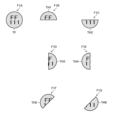
- FIG. 1 is a diagram for explaining identification of a half tablet.
- FIG. 2 is a front perspective view of the smartphone.
- FIG. 3 is a rear perspective view of the smartphone.
- FIG. 4 is a block diagram showing the electrical configuration of the smartphone.
- FIG. 5 is a block diagram showing the functional configuration of the drug identification device.
- FIG. 6 is a block diagram showing the electrical configuration of the learning device.
- FIG. 7 is a diagram illustrating an example of a learning dataset for generating a trained model.
- FIG. 8 is a block diagram showing the functional configuration of the learning device.
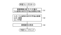
- FIG. 9 is a flowchart showing a method for learning a trained model according to the first embodiment.
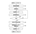
- FIG. 10 is a flowchart showing the medicine identification method according to the first embodiment.
- FIG. 10 is a flowchart showing the medicine identification method according to the first embodiment.
- FIG. 11 is a block diagram showing a functional configuration of a learning data acquisition unit according to the second embodiment.
- FIG. 12 is a diagram for explaining generation of images of learning data according to the second embodiment.
- FIG. 13 is a diagram for explaining generation of images of learning data according to the second embodiment.
- FIG. 14 is a diagram for explaining another example of generation of an image of learning data of an oval tablet.
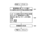
- FIG. 15 is a flowchart showing a method for learning a trained model according to the second embodiment.
- FIG. 16 is a flowchart showing a medicine identification method according to the second embodiment.
- FIG. 17 is a flowchart showing a method for learning a trained model according to the third embodiment.
- FIG. 18 is a flowchart showing a medicine identification method according to the third embodiment.
- FIG. 19 is a flowchart showing a method for learning a trained model according to the fourth embodiment.
- FIG. 20 is a flowchart showing a medicine identification method according to the fourth embodiment.
- FIG. 21 is a diagram for explaining an example of a captured image of a half tablet according to the fourth embodiment.
- FIG. 22 is a diagram for explaining another example of a captured image of a half tablet according to the fourth embodiment.
- a "full drug” is a drug that is not divided as shipped.
- An example of a full drug is a “full tablet” that is a non-divided tablet.
- a “tablet” is a solid drug that is molded into a certain shape by compression molding.
- a "round tablet” is a full tablet that is circular in plan view.
- an “oval tablet” is a full tablet that is oval in plan view. It is not necessary for the shape to be a mathematically strict oval shape.
- a "partial drug” is a drug that is a portion of a full drug that has been divided into multiple pieces.
- a partial drug is a "half tablet,” which is one of two halves of a full tablet.
- a “half tablet” is not limited to a full tablet that has been divided into two equal parts, but may be one of two halves of a full tablet.
- a “half tablet” is sometimes written as "1/2 tablet.”
- a partial drug is a "quarter tablet,” which is one of four pieces of a full tablet divided into two.
- a "quarter tablet” is not limited to a full tablet divided into four equal pieces, but can be any one of four pieces of a full tablet divided into two.
- a "quarter tablet” is sometimes written as "1/4 tablet.”
- the means for dividing tablets is not limited. Tablets may be divided manually using scissors, a cutter, a multi-tablet/half-tablet cutter, etc. Tablets may also be divided automatically using a dividing function installed in a packaging machine.
- an engraving is added means that identification information is formed by forming a groove, which is a recessed area, on the surface of the drug.
- the groove is not limited to being formed by digging into the surface, but may be formed by pressing the surface.
- the engraving may include an engraving that does not have an identification function, such as a score line.
- printed means that identification information is formed by applying edible ink or the like to the surface of the drug with or without contact.
- printed is synonymous with “printed.”
- engraving and/or printing means “either engraving or printing” or “both engraving and printing.” In this specification, “engraving and/or printing” may be abbreviated to “engraving and printing.”
- Fig. 1 is a diagram for explaining the identification of half tablets.
- F1A in Fig. 1 shows the front surface of a full tablet TF with the direction of the stamped print upright.
- the full tablet TF is, for example, a circular tablet with a diameter of 7.0 mm and a thickness of 2.4 mm.
- the front surface of the full tablet TF is stamped with "FF111".
- F1B in Figure 1 shows the front surface of half tablet TH1.
- Half tablet TH1 is the upper part when full tablet TF is divided into two parts, top and bottom, in a straight line as shown in Figure 1.
- the front surface of half tablet TH1 is stamped with "FF.”
- the drug type identification in this embodiment involves identifying the drug type of the full tablet TF from only the captured image of the half tablet TH1.
- F1C in Figure 1 shows the front surface of half tablet TH2.
- Half tablet TH2 is the lower part when full tablet TF is divided into two parts, top and bottom, in a straight line as shown in Figure 1.
- the front surface of half tablet TH2 is engraved with the numbers "111.”
- Drug type identification according to this embodiment includes identifying the drug type of the full tablet TF by combining a photographed image of the half tablet TH1 and a photographed image of the half tablet TH2. Drug type identification according to this embodiment also includes identifying the drug type of the full tablet TF from a photographed image in which the half tablet TH1 and the half tablet TH2 are arranged side by side.
- a half tablet is not limited to one that is divided into two pieces, one above and one below. Furthermore, a half tablet is not limited to one that is divided into two pieces by a straight line.
- F1D in FIG. 1 shows the front surface of half tablet TH3.
- Half tablet TH3 is the right part when full tablet TF is divided into two pieces, left and right, in a non-linear manner in the state shown in FIG. 1.
- F1E in FIG. 1 shows the front surface of half tablet TH4.
- Half tablet TH4 is the left part when full tablet TF is divided into two pieces, left and right, in a non-linear manner in the state shown in FIG. 1.
- F1E in FIG. 1 shows the front surface of half tablet TH5.
- Half tablet TH5 is the upper left part when full tablet TF is divided into two pieces, diagonally, in a non-linear manner in the state shown in FIG. 1.
- F1G in FIG. 1 shows the front surface of half tablet TH6.
- Half tablet TH6 is the lower right part when full tablet TF is divided into two pieces, diagonally, in a non-linear manner in the state shown in FIG. 1. In this way, the half tablet may be split in two in any direction, or at any position.
- the tablet may have a score line.
- Half tablets are not limited to those divided into two along the score line.
- the cutting line is not necessarily a straight line, and can have steps, resulting in a variety of different appearances.
- half tablets may be produced that have very little or no identifying information, such as markings/printing, that could serve as a clue to identifying the drug type. Furthermore, images of half tablets with very little or no identifying information become noise in the training data, so if such data is included in the training data for a drug type identification AI (Artificial Intelligence), the identification accuracy of the drug type identification AI will decrease.
- a drug type identification AI Artificial Intelligence
- Half a tablet of the drug to be identified may have the same or very similar appearance as a half tablet of a different drug.
- the drug identification device is a device that identifies the drug type of a drug to be identified from a captured image of the drug to be identified that has been marked and/or printed, and identifies the correct drug.
- the drug to be identified includes partial drugs that are a part of a full drug divided into multiple parts.
- the drug identification device is mounted on a mobile terminal device.
- the mobile terminal device includes at least one of a mobile phone, a PHS (Personal Handyphone System), a smartphone, a PDA (Personal Digital Assistant), a tablet computer terminal, a notebook personal computer terminal, and a portable game console.
- a drug identification device configured as a smartphone is given as an example and will be described in detail with reference to the drawings.
- FIG. 2 is a front perspective view of a smartphone 10, which is a camera-equipped mobile terminal device according to this embodiment.
- the smartphone 10 has a flat housing 12.
- the smartphone 10 has a touch panel display 14, a speaker 16, a microphone 18, and an in-camera 20 on the front side of the housing 12.
- the touch panel display 14 comprises a display section that displays images, etc., and a touch panel section that is disposed in front of the display section and accepts touch input.
- the display section is, for example, a color LCD (Liquid Crystal Display) panel.
- the touch panel unit is, for example, a capacitive touch panel provided in a planar manner on a light-transmitting substrate body, and has light-transmitting position detection electrodes and an insulating layer provided on the position detection electrodes.
- the touch panel unit generates and outputs two-dimensional position coordinate information corresponding to a user's touch operation. Touch operations include a tap operation, a double tap operation, a flick operation, a swipe operation, a drag operation, a pinch-in operation, and a pinch-out operation.
- the speaker 16 is an audio output unit that outputs audio during a call and when playing back a video.
- the microphone 18 is an audio input unit that inputs audio during a call and when shooting a video.
- the front camera 20 is an imaging device that shoots videos and still images.
- FIG 3 is a rear perspective view of the smartphone 10.
- the smartphone 10 has an outer camera 22 and a light 24 on the rear of the housing 12.
- the outer camera 22 is an imaging device that captures videos and still images.
- the light 24 is a light source that emits illumination light when capturing images with the outer camera 22, and is composed of, for example, an LED (Light Emitting Diode).
- the smartphone 10 has switches 26 on the front and side of the housing 12.
- the switches 26 are input members that accept instructions from the user.
- the switches 26 are push-button switches that turn on when pressed with a finger or the like, and turn off when the finger is released due to the restoring force of a spring or the like.
- the configuration of the housing 12 is not limited to this, and a configuration having a folding structure or a sliding mechanism may also be adopted.
- the smartphone 10 has, as its main function, a wireless communication function for performing mobile wireless communication with a base station device via a mobile communication network.
- FIG 4 is a block diagram showing the electrical configuration of the smartphone 10.
- the smartphone 10 includes the aforementioned touch panel display 14, speaker 16, microphone 18, in-camera 20, out-camera 22, light 24, and switch 26, as well as a CPU (Central Processing Unit) 28, a wireless communication unit 30, a call unit 32, memory 34, an external input/output unit 40, a GPS receiver unit 42, and a power supply unit 44.
- a CPU Central Processing Unit
- the CPU 28 is an example of a processor that executes instructions stored in the memory 34.
- the CPU 28 operates according to the control programs and control data stored in the memory 34, and controls each part of the smartphone 10.
- the CPU 28 has a mobile communication control function that controls each part of the communication system to perform voice communication and data communication through the wireless communication unit 30, and an application processing function.
- the CPU 28 also has an image processing function for displaying moving images, still images, text, etc. on the touch panel display 14. This image processing function visually conveys information such as still images, moving images, and text to the user.
- the CPU 28 also acquires two-dimensional position coordinate information corresponding to the user's touch operation from the touch panel portion of the touch panel display 14. Furthermore, the CPU 28 acquires an input signal from the switch 26.
- CPU28 The hardware structure of CPU28 is various processors as shown below.
- the various processors include a CPU (Central Processing Unit), which is a general-purpose processor that executes software (programs) and acts as various functional units, a GPU (Graphics Processing Unit), which is a processor specialized for image processing, a PLD (Programmable Logic Device), which is a processor whose circuit configuration can be changed after manufacture such as an FPGA (Field Programmable Gate Array), and a dedicated electrical circuit, such as an ASIC (Application Specific Integrated Circuit), which is a processor with a circuit configuration designed specifically to execute specific processing.
- CPU Central Processing Unit
- GPU Graphics Processing Unit
- PLD Programmable Logic Device
- ASIC Application Specific Integrated Circuit
- a single processing unit may be configured with one of these various processors, or may be configured with two or more processors of the same or different types (for example, multiple FPGAs, or a combination of a CPU and an FPGA, or a combination of a CPU and a GPU).
- Multiple functional units may also be configured with one processor.
- one processor is configured with a combination of one or more CPUs and software, as represented by a computer such as a client or server, and this processor acts as multiple functional units.
- a processor is used that realizes the functions of the entire system including multiple functional units with a single IC (Integrated Circuit) chip, as represented by a SoC (System On Chip).
- the various functional units are configured using one or more of the above-mentioned various processors as a hardware structure.
- the hardware structure of these various processors is an electrical circuit that combines circuit elements such as semiconductor elements.
- the in-camera 20 and the out-camera 22 take videos and still images according to instructions from the CPU 28.
- the in-camera 20 and the out-camera 22 have the same internal configuration.
- the in-camera 20 and the out-camera 22 each have a shooting lens, an image sensor, and an image processing unit (not shown).
- the in-camera 20 and the out-camera 22 each receive subject light through a photographing lens with an image sensor.
- the image sensor is a photoelectric conversion element such as a CMOS (Complementary Metal-Oxide Semiconductor) or a CCD (Charge-Coupled Device), and has R (red), G (green), and B (blue) color filters (not shown) on the light-receiving surface.
- the subject light is focused on the light-receiving surface of the image sensor, and the image sensor converts the subject light focused on the light-receiving surface into an electrical signal based on the R, G, and B color signals.
- the image processing unit performs predetermined processing on the analog image signal output from the image sensor to convert it into a digital image signal.
- the inner camera 20 and the outer camera 22 may convert the image data of the moving images and still images captured by them into compressed image data such as MPEG (Moving Picture Experts Group) or JPEG (Joint Photographic Experts Group).
- MPEG Motion Picture Experts Group
- JPEG Joint Photographic Experts Group
- the CPU 28 stores the video and still images captured by the in-camera 20 and the out-camera 22 in the memory 34.
- the CPU 28 may also output the video and still images captured by the in-camera 20 and the out-camera 22 to the outside of the smartphone 10 via the wireless communication unit 30 or the external input/output unit 40.
- the CPU 28 displays the video and still images captured by the in-camera 20 and the out-camera 22 on the touch panel display 14.
- the CPU 28 may use the video and still images captured by the in-camera 20 and the out-camera 22 within application software.
- the CPU 28 may illuminate the subject with auxiliary light by turning on the light 24 when capturing an image with the rear camera 22.
- the light 24 may be turned on and off by the user's touch operation on the touch panel display 14 or by operating the switch 26.
- the wireless communication unit 30 performs wireless communication with a base station device contained in the mobile communication network according to instructions from the CPU 28.
- the smartphone 10 uses this wireless communication to send and receive various file data such as audio data and image data, e-mail data, etc., and to receive Web (abbreviation for World Wide Web) data, streaming data, etc.
- Web abbreviation for World Wide Web
- the speaker 16 and microphone 18 are connected to the communication unit 32.
- the communication unit 32 decodes the voice data received by the wireless communication unit 30 and outputs it from the speaker 16.
- the communication unit 32 converts the user's voice input through the microphone 18 into voice data that can be processed by the CPU 28 and outputs it to the CPU 28.
- Memory 34 stores instructions to be executed by CPU 28.
- Memory 34 is composed of an internal storage unit 36 built into smartphone 10, and an external storage unit 38 that is detachable from smartphone 10. Internal storage unit 36 and external storage unit 38 are realized using known storage media.
- Memory 34 stores the control program of CPU 28, control data, application software, address data associated with names and telephone numbers of communication partners, data of sent and received e-mails, web data downloaded by web browsing, downloaded content data, etc. Memory 34 may also temporarily store streaming data, etc.
- the external input/output unit 40 acts as an interface with external devices connected to the smartphone 10.
- the smartphone 10 is directly or indirectly connected to other external devices by communication or the like via the external input/output unit 40.
- the external input/output unit 40 transmits data received from external devices to each component inside the smartphone 10, and also transmits data inside the smartphone 10 to external devices.
- the means of communication include, for example, Universal Serial Bus (USB), Institute of Electrical and Electronics Engineers (IEEE) 1394, the Internet, wireless LAN (Local Area Network), Bluetooth (registered trademark), RFID (Radio Frequency Identification), and infrared communication.
- the external devices include, for example, headsets, external chargers, data ports, audio equipment, video equipment, smartphones, PDAs, personal computers, and earphones.
- the GPS receiver 42 detects the position of the smartphone 10 based on positioning information from GPS satellites ST1, ST2, ..., STn.
- the power supply unit 44 is a power supply source that supplies power to each part of the smartphone 10 via a power supply circuit (not shown).
- the power supply unit 44 includes a lithium ion secondary battery.
- the power supply unit 44 may also include an A/D conversion unit that generates a DC voltage from an external AC power source.
- the smartphone 10 configured in this manner can be set to a shooting mode in response to user input of instructions using the touch panel display 14 or the like, and can capture video and still images using the in-camera 20 and out-camera 22.
- the smartphone 10 When the smartphone 10 is set to the shooting mode, it goes into a shooting standby state, a video is shot by the in-camera 20 or the out-camera 22, and the shot video is displayed on the touch panel display 14 as a live view image.
- the user can visually check the live view image displayed on the touch panel display 14 to determine the composition, confirm the subject they want to capture, and set the shooting conditions.
- the smartphone 10 When the smartphone 10 is in standby for shooting and receives a shooting instruction from a user using the touch panel display 14 or the like, it performs AF (Autofocus) and AE (Auto Exposure) control, and shoots and stores videos and still images.
- AF Autofocus
- AE Automatic Exposure
- Fig. 5 is a block diagram showing a functional configuration of the drug identification device 100 realized by the smartphone 10. Each function of the drug identification device 100 is realized by the CPU 28 executing a drug identification program stored in the memory 34. As shown in Fig. 5, the drug identification device 100 includes an image acquisition unit 102, a drug detection unit 104, an imprinted character extraction unit 106, a drug type recognition unit 108, a candidate output unit 110, and a determination unit 112.
- the image acquisition unit 102 acquires a captured image of the drug to be identified to which the imprint has been added.
- the captured image is, for example, an image captured by the in-camera 20 or the out-camera 22.
- the captured image may also be an image acquired from another device via the wireless communication unit 30, the external storage unit 38, or the external input/output unit 40.
- the captured image may be an image of the drug to be identified and a marker. There may be multiple markers, and the marker may be an ArUco marker.
- the captured image may be an image of the drug to be identified and a reference gray color.
- the captured image may be an image captured at a standard shooting distance and shooting viewpoint.
- the shooting distance can be expressed by the distance between the drug to be identified and the shooting lens, and the focal length of the shooting lens.
- the shooting viewpoint can be expressed by the angle between the marker print surface and the optical axis of the shooting lens.
- the captured image may include multiple drugs to be identified.
- the multiple drugs to be identified are not limited to drugs of the same type, but may be drugs of different types.
- the drugs to be identified may include full drugs or partial drugs.
- the image acquisition unit 102 may standardize the shooting distance and shooting viewpoint of the captured image based on the marker to acquire a standardized image.
- the image acquisition unit 102 may perform color correction of the captured image based on the reference gray color.
- the drug detection unit 104 detects the area of the drug to be identified from the captured image acquired by the image acquisition unit 102. If a standardized image is acquired by the image acquisition unit 102, the drug detection unit 104 detects the area of the drug to be identified from the standardized image. If the captured image contains multiple drugs to be identified, the drug detection unit 104 detects the areas of each of the multiple drugs to be identified.
- the imprint extraction unit 106 processes at least the area of the drug to be identified in the captured image, removes edge information of the drug to be identified that may become noise in drug identification, and obtains an imprint extraction image from which the imprint has been extracted.
- the imprint extraction image is an image in which the imprint has been emphasized by expressing the brightness of the imprint portion (hereinafter referred to as the imprint portion) as being relatively higher than the brightness of the portion other than the imprint portion.
- the imprint extraction image may be an image in which the imprint portion is white and the portion other than the imprint portion is black.
- the imprint extraction unit 106 acquires multiple imprint extraction images that respectively correspond to the multiple target drugs.
- the imprint extraction unit 106 may include a trained model that outputs an image in which the imprint of the drug has been extracted when an image of the drug with imprint added is given as input.
- the drug type recognition unit 108 inputs the stamp print extraction image, infers the drug type of the drug to be identified, and obtains candidate drug types for the drug to be identified.
- the candidate drug types include drug identification information consisting of drug name, product name, abbreviation, or a combination of these.
- the drug type recognition unit 108 includes a trained model 108A (an example of a "first trained model").
- the trained model 108A is a trained model that, when an image in which a drug's imprint is extracted is given as input, outputs the drug type of the drug corresponding to the imprint.
- the trained model 108A may output multiple drug types.
- the trained model 108A may output, together with the drug type, a score or probability indicating the likelihood that the drug type corresponds to the imprint.
- the trained model 108A is a model that has undergone machine learning using an image in which the imprinting of a full drug to which imprinting has been added has been extracted.
- the trained model 108A is a training data set of a plurality of different drugs to which imprinting has been added, and machine learning has been performed using a training data set for learning that is a set of a first image of the drug from which the imprinting has been extracted and the drug type corresponding to the imprinting.
- the first image is, for example, an image from which the imprinting of a full drug has been extracted.
- the first image may be an image that has been processed from an image from which the imprinting of a full drug has been extracted.
- the trained model 108A may apply a convolutional neural network (CNN).
- CNN convolutional neural network
- the drug type recognition unit 108 performs recognition based on the information printed on the seal without using color information, making it robust against the effects of the shooting environment.
- the candidate output unit 110 outputs candidates for the drug type of the drug to be identified that are acquired by the drug type recognition unit 108.
- the candidate output unit 110 may output multiple candidates for drug types for which the trained model 108A has a relatively high score.
- the candidate output unit 110 for example, displays multiple candidates for the drug type of the drug to be identified on the touch panel display 14 in a selectable manner.
- the confirmation unit 112 confirms the correct drug from among the candidate drug types of the drug to be identified.
- the confirmation unit 112 confirms, for example, the candidate drug type selected by the user from multiple candidate drug types of the drug to be identified displayed on the touch panel display 14 as the correct drug. If there is only one candidate drug type of the drug to be identified output by the candidate output unit 110, the confirmation unit 112 may confirm that candidate drug type as the correct drug.
- [Electrical configuration of the learning device] 6 is a block diagram showing the electrical configuration of a learning device 120 that generates the trained model 108 A.
- a learning device 120 a personal computer or a workstation can be used.
- the learning device 120 includes a learning data acquisition unit 122, a database 124, an operation unit 126, a display unit 128, a CPU 130, a RAM (Random Access Memory) 132, and a ROM (Read Only Memory) 134.
- the learning data acquisition unit 122 is an interface that acquires the learning data set stored in the database 124, and includes wired and wireless communication interfaces.
- the database 124 is a memory unit that stores the learning dataset, and is configured from a large-capacity storage device.
- the learning dataset will be described later.
- the operation unit 126 is a user interface that allows the user to control the learning device 120, and is composed of a keyboard and a pointing device.
- the display unit 128 is an output interface that visually displays the status of the learning device 120, and is composed of a display panel.
- CPU 130 is a processor that executes instructions stored in RAM 132 and ROM 134, and has the same hardware structure as CPU 28.
- RAM 132 is a memory device that temporarily stores data used by CPU 130 for various calculations, and is composed of a semiconductor memory.
- ROM 134 is a memory device that stores programs to be executed by CPU 130, and is composed of a hard disk.
- the learning data set is stored in the database 124.
- the learning data set is a set of a plurality of different engraved and printed extracted images of drugs, and information on the drug type and the front and back of the engraved and printed extracted images, which are correct data.
- the engraved and printed extracted images included in the learning data set have a certain size according to the trained model 108A.
- the engraved and printed extracted image I01 and the information on the drug type D01 and the front side of the engraved and printed extracted image I01 constitute one learning data set.
- the engraved and printed extracted image I02 and the information on the drug type D02 and the front side of the engraved and printed extracted image I02 constitute one learning data set
- the engraved and printed extracted image I03 and the information on the drug type D03 and the back side of the engraved and printed extracted image I03 constitute one learning data set.
- FIG. 8 is a block diagram showing the functional configuration of the learning device 120. As shown in FIG. 8, the learning device 120 includes a recognizer 140, an error calculation unit 142, and a parameter control unit 144.
- the recognizer 140 is a CNN.
- the recognizer 140 changes from an untrained model to a trained model by updating the parameters from the initial values to optimal values.
- the initial values of the parameters of the recognizer 140 may be any value, or the parameters of an existing trained model may be applied.
- the recognizer 140 includes an input layer 140A, an intermediate layer 140B, and an output layer 140C.
- the input layer 140A, the intermediate layer 140B, and the output layer 140C are structured such that multiple nodes are connected by edges.
- a certain size of stamp print extraction image from the learning dataset is input to the input layer 140A.
- the intermediate layer 140B is a layer that extracts features from the engraved print extraction image input from the input layer 140A.
- the intermediate layer 140B has multiple sets, each of which is a convolutional layer and a pooling layer, and a fully connected layer.
- the fully connected layer connects all of the nodes in the previous layer (here, the pooling layer).
- the output layer 140C is a layer that outputs the drug type, which is the recognition result of the recognizer 140.
- the error calculation unit 142 obtains the recognition result output from the output layer 140C of the recognizer 140 and the drug type of the drug in the learning data set of the imprinted and printed extracted image input to the input layer 140A, and calculates the error between the two. Possible methods for calculating the error include, for example, softmax cross entropy or least squared error (MSE: Mean Squared Error).
- MSE Mean Squared Error
- the parameter control unit 144 adjusts the parameters of the recognizer 140 using the backpropagation method based on the error calculated by the error calculation unit 142.
- the parameters include, for example, the coefficients of the filters in the convolution layer.
- This parameter adjustment process is repeated, and learning is repeated until the difference between the output of the recognizer 140 and the correct data becomes small.
- the learning device 120 performs learning in this manner, and generates a trained recognizer 140 with optimized parameters as a trained model 108A. Note that appropriate noise may be artificially added to the extracted images of the drug imprints in the learning data set. This makes it possible to generate a trained model 108A that is robust to fluctuations in the imaging environment.
- the input image is an image extracted from the imprint on one side (single side) of the medicine, but a set of images extracted from the imprint on both sides may also be used as the input image.
- the amount of information is greater than when only one side is used, so improved accuracy can be expected, but usability is reduced because both sides must be photographed in succession.
- the recognizer 140 which is the trained model 108A, outputs the drug type that corresponds to the imprint.
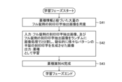
- First Embodiment [Learning Phase] 9 is a flowchart showing a learning method of the trained model 108A according to the first embodiment in the learning device 120.
- the learning method is realized by the CPU 130 reading and executing a learning program from the ROM 134.
- the learning program may be provided to the learning device 120 via an input interface (not shown).
- step S1 the learning device 120 prepares a learning dataset.
- the learning dataset includes an extracted image of the medicine's imprint, and information on the drug type and the front and back of the extracted image of the imprint, which is the correct answer data.
- the learning device 120 prepares a large number of extracted images of the imprint of full tablets linked to drug type information from the database 124.
- step S2 the learning device 120 trains the recognizer 140 by inputting the image of the stamp print extraction of the full tablet and outputting the drug type. That is, the learning device 120 calculates the error between the output result of the output layer 140C when the image of the stamp print extraction of the learning data set is input to the input layer 140A and the drug type of the learning data set in the error calculation unit 142, and adjusts the parameters of the recognizer 140 in the parameter control unit 144 based on the calculated error.
- trained model 108A which is a drug type identification AI that identifies the drug type of a full tablet, in step S3.
- [Utilization phase] 10 is a flowchart showing the drug identification method according to the first embodiment in the drug identification device 100.
- the drug identification method is realized by the CPU 28 reading and executing a drug identification program from the memory 34.
- the drug identification program may be provided via the wireless communication unit 30 or the external input/output unit 40.
- the identification process for half tablets will be described.
- step S11 the drug identification device 100 captures an image of multiple tablets with the outer camera 22.
- the multiple tablets may be packaged in a single sachet.
- the image acquisition unit 102 acquires an image of the multiple tablets.
- step S12 the drug detection unit 104 detects areas of multiple tablets from the image captured in step S11.
- steps S13 to S16 are repeated for each tablet area detected in step S12.
- step S13 the drug detection unit 104 extracts one tablet image to be identified from the captured image taken in step S11.
- the tablet image is an image in which the areas of each individual tablet are extracted from the captured image.
- step S14 the drug detection unit 104 determines whether the tablet shown in the tablet image extracted in step S13 is a half tablet. If it is determined to be a full tablet in step S14, i.e., if the determination is No in step S14, the processing for this tablet ends and the processing proceeds to step S13 for a different tablet. If it is determined to be a half tablet in step S14, i.e., if the determination is Yes in step S14, the processing proceeds to step S15.
- step S15 the engraving extraction unit 106 obtains an engraving extraction image from the tablet image extracted in step S13.
- step S16 the drug type recognition unit 108 inputs the stamp print extraction image acquired in step S15 into the trained model 108A generated in steps S1 to S3, and acquires multiple drug type candidates for the half tablet in the image.
- the candidate output unit 110 displays on the touch panel display 14 multiple drug type candidates for the half tablet acquired by the drug type recognition unit 108 that have relatively high scores.
- the confirmation unit 112 confirms the drug type candidate selected by the user from among the multiple displayed drug type candidates as the correct drug.
- the first embodiment has the following features.
- problems 1 and 2 can be solved by features A1 and A2
- problems 3 and 4 can be solved by features A2 and the latter part of A2
- problem 5 can be solved by feature A3.
- Second Embodiment [Generation of learning data] ⁇ Functional configuration of the learning device> 11 is a block diagram showing a functional configuration of the learning data acquisition unit 122 according to the second embodiment.
- learning data is generated in the learning data acquisition unit 122 of the learning device 120
- the learning data acquisition unit 122 artificially generates a pseudo half tablet stamp print extraction image as the learning data.
- the learning data acquisition unit 122 includes an engraving/printing extraction image acquisition unit 152, a random rotation unit 154, a random translation unit 156, a cutting unit 158, a determination unit 160, and a placement unit 162.
- the engraving extraction image acquisition unit 152 acquires an engraving extraction image of a full tablet from the database 124.
- the engraving extraction image acquisition unit 152 may acquire an engraving extraction image of a full tablet by acquiring a photographed image of the full tablet, detecting the area of the full tablet from the acquired photographed image, and extracting the engraving from the detected area.
- the random rotation unit 154 performs a rotation process to rotate the engraving print extraction image acquired by the engraving print extraction image acquisition unit 152 at a random angle around the center of the engraving print extraction image.
- the random translation unit 156 performs translation processing to translate the engraved print extraction image rotated by the random rotation unit 154 by a random amount of movement.
- the cutting unit 158 cuts the engraved print extraction image translated by the random translation unit 156 along a cutting axis whose orientation and position are fixed in advance, dividing it into two, and generates two divided engraved print extraction images.
- the generation of the divided engraved print extraction image is not limited to the example of rotating and translating the engraved print extraction image and then cutting it at a fixed cutting axis, as long as the relationship between the engraved print extraction image and the cutting axis involves rotation and translation.
- the cutting axis may be rotated at a random angle in the random rotation unit 154 and then translated in the random translation unit 156.
- the fixed engraved print extraction image is cut at the cutting axis after rotation and translation.
- the determination unit 160 determines whether or not to adopt the divided stamp-print extracted image as learning data. For example, the determination unit 160 determines whether to adopt as learning data a divided stamp-print extracted image that contains more stamp-print information than a certain standard.
- the certain standard is 20%, preferably 30%, and more preferably 40%, when the stamp-print information amount of the stamp-print extracted image before division is 100%.
- the total pixel value of the stamp-print is used as the information amount. For example, if the total pixel value of the stamp-print of the divided stamp-print extracted image is more than 30% of the total pixel value of the stamp-print of the stamp-print extracted image before division, the determination unit 160 determines to adopt the divided stamp-print extracted image as learning data.
- the determination unit 160 determines to exclude the divided stamp-print extracted image from the learning data.
- the determination unit 160 determines whether or not to use each of the two divided stamp print extraction images generated by the cutting unit 158 as learning data.
- the placement unit 162 generates a training image having the input size of the trained model 108A.
- the training image is an image in which the divided stamped print extraction image that has been determined by the determination unit 160 to be used as training data is placed at the center.
- the background area of the training image other than the area in which the divided stamped print extraction image is placed has the same brightness as the brightness of the parts of the divided stamped print extraction image other than the stamped print part. For example, if the parts of the divided stamped print extraction image other than the stamped print part are black, the background area of the training image is black.
- F12A in FIG. 12 shows the front surface of the circular tablet TC with the engraving oriented upright.
- the engraving "FF111" is added to the front surface of the circular tablet TC.
- F12B in FIG. 12 shows an engraving extraction image I11 of the front surface of the circular tablet TC.
- the engraving extraction image I11 is obtained by extracting the engraving from the captured image of the front surface of the circular tablet TC using the engraving extraction process P1 in the engraving extraction image acquisition unit 152.
- the center of the engraving extraction image I11 coincides with the center of the circular tablet TC.
- F12C in FIG. 12 shows the engraved print extraction image I12.
- the engraved print extraction image I12 is obtained by rotating the engraved print extraction image I11 by the random rotation process P2 in the random rotation unit 154.
- the engraved print extraction image I12 is an image in which the engraved print extraction image I11 has been rotated clockwise by an angle ⁇ .
- the random rotation unit 154 may determine the angle ⁇ to be any value greater than or equal to 0 degrees and less than 360 degrees.
- the background area BG1 of the engraved print extraction image I12 shown in F12C is an area for image processing, and the target engraved print extraction image is rotated and translated within the background area BG1.
- the center of the background area BG1 is at the same position as the center of the engraved print extraction image I11.
- the engraving print extraction image I13 is obtained by translating the engraving print extraction image I12 using the random translation process P3 in the random translation unit 156. Note that the background region BG1 is fixed and is not translated in the random translation process P3.
- the engraving print extraction image I13 is an image obtained by translating the engraving print extraction image I12 by ⁇ x in the horizontal direction and ⁇ y in the vertical direction in FIG. 12.
- the random translation unit 156 may determine ⁇ x and ⁇ y to be any value including 0.
- F12E in FIG. 12 shows how the engraved print extraction image I13 is cut along the center line LC, which is the cutting axis, by the cutting process P4 in the cutting unit 158.
- the center line LC is a straight line parallel to the vertical direction in FIG. 12 and passes through the center of the background region BG1.
- F12F in FIG. 12 shows the divided stamp-print extraction image I14, which is one side of the stamp-print extraction image I13 that has been cut and separated by cutting process P4.
- F12G in FIG. 12 shows the divided stamp-print extraction image I15, which is the other side of the stamp-print extraction image I13 that has been cut and separated by cutting process P4.
- the divided stamp-print extraction images I14 and I15 each correspond to an image that is a part of the stamp-print extraction image I13 that has been divided in an arbitrary direction and position.
- the F12H in FIG. 12 shows the result RT1 of the divided stamp print extracted image I14 judged by the judgment process P5 in the judgment unit 160.
- the judgment process P5 is a process for judging that the divided stamp print extracted image containing more than a certain amount of stamp print information should be adopted as learning data.
- the result RT1 is adoption as learning data.
- the divided stamp print extracted image I14 is an image in which the stamp print extracted image I13 is divided in an arbitrary direction and position, and corresponds to an image containing more than a certain amount of stamp print information.
- F12I in FIG. 12 shows the result RT2 of the divided stamp print extraction image I15 judged by the judgment process P5.
- the result RT2 is not adopted (excluded) as learning data.
- F12J in FIG. 12 shows a training image I16 generated from the divided stamp-print extracted image I14 (an example of a "second image").
- the training image I16 is generated by arranging the stamp-print portion of the divided stamp-print extracted image I14 at the center by the arrangement process P6 in the arrangement unit 162. Alternatively, for the purpose of increasing data, the stamp-print portion of the divided stamp-print extracted image I14 may be arranged by shifting it randomly from the center.
- the training image I16 has the input size of the trained model 108A.
- ⁇ In the case of oval tablets> 13 is a diagram for explaining generation of an image of training data according to the second embodiment, showing the case of an oval tablet.
- the region of the oval tablet is divided in half along the minor axis direction to generate an image of the training data.
- F13A in FIG. 13 shows the front surface of the oval lock TE1 with its long axis oriented parallel to the horizontal direction in FIG. 13.
- the front surface of the oval lock TE1 is marked with the inscription "FF222.”
- F13B in FIG. 13 shows an inscription print extraction image I21 of the front surface of the oval lock TE1.
- the inscription print extraction image I21 is obtained by extracting the inscription print from the captured image of the front surface of the oval lock TE1 by the inscription print extraction process P1 in the inscription print extraction image acquisition unit 152.
- the center of the inscription print extraction image I21 in the horizontal direction in FIG. 13 coincides with the center of the long axis direction of the oval lock TE1.
- F13C in FIG. 13 shows the divided stamp print extracted images I22 and I23.
- the divided stamp print extracted images I22 and I23 are obtained by cutting the stamp print extracted image I21 at the center line LC parallel to the minor axis direction of the oval tablet TE1 by cutting process P4 in the cutting unit 158.
- F13C in FIG. 13 shows the results RT11 and RT12 of the divided stamp print extracted images I22 and I23 being judged by judgment process P5 in the judgment unit 160.
- the results RT11 and RT12 are each adopted as learning data.
- F13D in FIG. 13 shows the divided stamp-print extracted image I22.
- F13E in FIG. 13 shows a learning image I24 generated from the divided stamp-print extracted image I22.
- the learning image I24 is generated by arranging the stamp-print portion of the divided stamp-print extracted image I22 at the center by the arrangement process P6 in the arrangement unit 162.
- the stamp-print portion of the divided stamp-print extracted image I22 may be arranged to be randomly shifted from the center for the purpose of increasing data.
- the learning image I24 has the input size of the trained model 108A.
- the arrangement process P6 also generates a learning image from the divided stamp-print extracted image I23.
- FIG. 13 shows the front surface of the oval tablet TE2, which has a similar imprint to that of the oval tablet TE1.
- the imprint "FF333" is added to the front surface of the oval tablet TE2.
- the oval tablets TE1 and TE2 have the imprint "FF” in common. Therefore, the split imprint extraction image I22 can also be generated from the imprint extraction image of the oval tablet TE2.
- the imprint extraction image (or split imprint extraction image) of the oval tablet TE1 and the imprint extraction image (or split imprint extraction image) of the oval tablet TE2 respectively, it is expected that the drugs of both the oval tablet TE1 and the oval tablet TE2 will be output as candidates. For this reason, although it is not possible to automatically identify the type of drug, it has the effect of narrowing down the candidates and presenting them to the user.
- Figure 14 is a diagram to explain another example of generating images of training data for an oval tablet.
- F14A in FIG. 14 shows the front surface of the oval lock TE3.
- the letters "qq" are engraved on the front surface of the oval lock TE3.
- F14B in FIG. 14 shows the engraving print extraction image I31.
- the engraving print extraction image I31 is obtained by extracting the engraving print from the captured image of the front surface of the oval lock TE3 by the engraving print extraction process P1 in the engraving print extraction image acquisition unit 152.
- F14C in FIG. 14 shows divided stamp print extraction images I32 and I33.
- Divided stamp print extraction images I32 and I33 are obtained by cutting stamp print extraction image I31 at center line LC by cutting process P4 in cutting unit 158.
- F14C in FIG. 14 shows results RT21 and RT22 obtained by judging divided stamp print extraction images I32 and I33, respectively, by judgment process P5 in judgment unit 160. Result RT21 is adopted as learning data, and result RT22 is not adopted as learning data.
- the stamp information of the divided stamp print extraction image I33 is insufficient for drug type identification, so it is excluded from the learning data.
- the certain criteria used in the judgment process P5 in the judgment unit 160 may be the same as those for circular tablets.
- FIG. 15 is a flowchart showing a learning method for the trained model 108A according to the second embodiment in the learning device 120.
- step S21 the learning device 120 prepares extracted images of the imprinted markings of a large number of full tablets linked to drug type information from the database 124.
- the learning device 120 trains the recognizer 140 using the pseudo half tablet stamp print extraction image as input and the drug type as output.
- the pseudo half tablet stamp print extraction image is, for example, a split stamp print extraction image created by randomly splitting the stamp print extraction image of a full tablet into two using image processing to generate various patterns of appearance.
- the split stamp print extraction image is also used as learning data in the judgment process P5 in the judgment unit 160, as explained using Figures 12 to 14.
- step S23 trained model 108A, which is a drug type identification AI, is completed. Trained model 108A trained in this way becomes a drug type identification AI dedicated to half tablets, and is a different model from the drug type identification AI for full tablets.
- FIG. 16 is a flowchart showing a drug identification method according to the second embodiment in the drug identification device 100.
- step S31 the drug identification device 100 captures an image of multiple tablets with the outer camera 22.
- the multiple tablets may be packaged in a single sachet.
- the image acquisition unit 102 acquires an image of the multiple tablets.
- step S32 the drug detection unit 104 detects areas of multiple tablets from the image captured in step S31.
- steps S33 to S36 are repeated for each tablet area detected in step S32.
- step S33 the drug detection unit 104 extracts one tablet image to be identified from the image captured in step S31.
- step S34 the drug detection unit 104 determines whether the tablet shown in the tablet image extracted in step S33 is a half tablet. If it is determined to be a full tablet in step S34, i.e., if the determination is No in step S34, the processing for this tablet ends and the process moves to step S33 for a different tablet. If it is determined to be a half tablet in step S34, i.e., if the determination is Yes in step S34, the process moves to step S35.
- step S35 the engraving extraction unit 106 obtains an engraving extraction image from the tablet image extracted in step S33.
- step S36 the drug type recognition unit 108 inputs the stamp print extraction image acquired in step S35 into the trained model 108A generated in steps S21 to S23, and acquires multiple drug type candidates for the half tablet.
- the candidate output unit 110 displays on the touch panel display 14 multiple drug type candidates for the half tablet acquired by the drug type recognition unit 108 that have relatively high scores.
- the confirmation unit 112 confirms the drug type candidate selected by the user from among the multiple displayed drug type candidates as the correct drug.
- the second embodiment is similar to the first embodiment in that full tablet images are used for learning, but the learning method is devised to improve the accuracy of identifying half tablets.
- the second embodiment has the following features.
- the trained model 108A is trained using an image of the full medicine stamp extraction. However, during training, the trained model is trained using a pseudo image of the half tablet stamp extraction generated from the full medicine stamp extraction image.
- Feature B3 For images generated by Feature B2, if the amount of information is low based on the pixel values, the image is automatically excluded from the learning data.
- the above problems 1 and 2 can be solved by feature B1, and problem 3 can be solved by feature B2. Also, according to the second embodiment, the above problem 3 can be solved by features B2 and B3, and problem 5 can be solved by feature B4.
- FIG. 17 is a flowchart showing a learning method for the trained model 108A according to the third embodiment in the learning device 120.
- step S41 the learning device 120 prepares extracted images of the imprinted markings of a large number of full tablets linked to drug type information from the database 124.
- step S42 the learning device 120 inputs the stamp-printed extracted image of a full tablet similar to that in the first embodiment and the stamp-printed extracted image of a pseudo half tablet similar to that in the second embodiment, and outputs the drug type to train the recognizer 140.
- step S43 trained model 108A, which is a drug type identification AI, is completed. Trained model 108A trained in this way becomes a drug type identification AI that can identify both full tablets and partial drugs.
- FIG. 18 is a flowchart showing a drug identification method according to the third embodiment in the drug identification device 100.
- step S51 the drug identification device 100 captures an image of multiple tablets using the outer camera 22.
- the multiple tablets may be packaged in a single sachet.
- the image acquisition unit 102 acquires an image of the multiple tablets.
- step S52 the drug detection unit 104 detects areas of multiple tablets from the image captured in step S51.
- steps S53 to S55 are repeated for each tablet area detected in step S52.
- step S53 the drug detection unit 104 extracts one tablet image to be identified from the image captured in step S51.
- step S54 the engraving extraction unit 106 obtains an engraving extraction image from the tablet image extracted in step S53.
- step S55 the drug type recognition unit 108 inputs the engraved print extraction image acquired in step S54 into the trained model 108A generated in steps S41 to S43, and acquires multiple drug type candidates for the tablet.
- the candidate output unit 110 displays on the touch panel display 14 the multiple drug type candidates for the tablet acquired by the drug type recognition unit 108, including multiple drug type candidates with relatively high scores.
- the confirmation unit 112 confirms the drug type candidate selected by the user from among the multiple displayed drug type candidates as the correct drug.
- a learning method is devised to improve the accuracy of identifying half tablets.
- a drug type identification AI can be used for both full tablets and half tablets, and it is no longer necessary to classify each tablet cutout image as a full drug or a partial drug, or to separate processing for full drugs from processing for partial drugs.
- the third embodiment has the following features.
- Feature C3 For images generated by Feature C2, if the amount of information is low based on the pixel values, the image is automatically excluded from the learning data.
- the above problems 1 and 2 can be solved by feature C1, and problem 3 can be solved by feature C2. Also, according to the third embodiment, the above problem 3 can be solved by features C2 and C3, and problem 5 can be solved by feature C4.
- FIG. 19 is a flowchart showing a learning method for the trained model 108A according to the fourth embodiment in the learning device 120.
- step S61 the learning device 120 prepares extracted images of the imprinted markings of a large number of full tablets linked to drug type information from the database 124.
- step S62 the learning device 120 trains the recognizer 140 using the extracted image of the imprinted mark on the full tablet as input and the drug type as output, similar to the first embodiment.
- trained model 108A which is a drug type identification AI that identifies the drug type of a full tablet, in step S63.
- FIG. 20 is a flowchart showing a drug identification method according to the fourth embodiment in the drug identification device 100.
- step S71 the drug identification device 100 captures an image of the half tablet with the outer camera 22.
- the image acquisition unit 102 acquires an image of the half tablet.
- FIG. 21 is a diagram for explaining an example of a photographed image of a half tablet acquired in step S71.
- F21A in FIG. 21 shows a state in which half tablet TH11 (an example of a "first partial drug") and half tablet TH12 (an example of a "second partial drug"), which were originally one full tablet TF (see FIG. 1, an example of a "first drug”), are arranged with their dividing lines physically close to each other to reproduce the full tablet TF before division.
- F21B in FIG. 21 shows a photographed image I41 (an example of a "third photographed image") taken with half tablet TH11 and half tablet TH12 arranged as shown in F21A.
- the image acquisition unit 102 acquires the photographed image I41.
- step S72 the drug detection unit 104 detects the area of half tablet TH11 and the area of half tablet TH12 from the captured image I41 acquired in step S71.
- steps S73 to S75 are repeated for each full tablet area detected in step S72.
- step S73 the drug detection unit 104 extracts one tablet image to be identified from the captured image I41 acquired in step S71.
- step S74 the imprint extraction unit 106 processes at least the half tablet TH11 area and the half tablet TH12 area of the tablet image extracted in step S73 to obtain an imprint extraction image (an example of a "second imprint extraction image").
- step S75 the drug type recognition unit 108 inputs the stamped and printed extracted image acquired in step S74 into the trained model 108A generated in steps S51 to S53, and acquires multiple drug type candidates for the original full tablet TF before it was divided into the half tablet TH11 and the half tablet TH12.
- the candidate output unit 110 displays on the touch panel display 14 the multiple drug type candidates for the full tablet TF acquired by the drug type recognition unit 108, including multiple drug type candidates with relatively high scores.
- the confirmation unit 112 confirms the drug type candidate selected by the user from among the multiple displayed drug type candidates as the correct drug.
- steps S73 to S75 are performed for all reproduced full tablets detected in step S72, and the drug identification device 100 ends the process in this flowchart.
- FIG. 22 is a diagram for explaining another example of a photographed image of a half tablet acquired in step S71.
- F22A in FIG. 22 shows a photographed image I42 (an example of a "first photographed image") of a half tablet TH11 and a photographed image I43 (an example of a "second photographed image") of a half tablet TH12, which were photographed separately.
- F22B in FIG. 22 shows a composite image I44 obtained by arranging the area of the half tablet TH11 in photographed image I42 and the area of the half tablet TH12 in photographed image I43 close to each other so as to reproduce the original full tablet TF.
- the image acquisition unit 102 acquires the composite image I44 thus synthesized.
- the image acquisition unit 102 may acquire the composite image I44 by compositing the photographed image I42 and the photographed image I43 using a dedicated GUI (Graphical User Interface).
- GUI Graphic User Interface
- step S72 the drug detection unit 104 detects the area of the full tablet TF from the composite image I44 acquired in step S71.
- step S73 the drug detection unit 104 extracts a tablet image to be identified from the composite image I44 acquired in step S71.
- the engraving extraction unit 106 processes at least the area of the full tablet TF of the tablet image extracted in step S73 to obtain an engraving extraction image (an example of a "first engraving extraction image"). It is preferable that the engraving extraction unit 106 processes the area of the dividing line so as not to extract it as an engraving.
- step S75 the drug type recognition unit 108 inputs the imprinted and printed extracted image acquired in step S74 into the trained model 108A to acquire multiple drug type candidates for the full tablet TF.
- the candidate output unit 110 displays on the touch panel display 14 multiple drug type candidates for the full tablet TF acquired by the drug type recognition unit 108, including multiple drug type candidates with relatively high scores.
- the confirmation unit 112 confirms the drug type candidate selected by the user from the multiple displayed drug type candidates as the correct drug.
- the input images are either (1) images of multiple divided tablets that were originally a single full tablet, photographed separately, and arranged on a dedicated GUI to approximate a single full tablet, or (2) images of multiple divided tablets that were originally a single full tablet, physically arranged and photographed to approximate a single full tablet.
- the above problems 1 and 2 can be solved by features D1, D2, and D4, and problem 3 can be solved by features D2 and D4. Also, according to the fourth embodiment, the above problem 4 can be solved by feature D4, and problem 5 can be solved by features D3 and D4.
- the smartphone 10 alone constitutes the drug identification device 100, which identifies the correct drug among the drugs to be identified that have an imprinted mark added thereto.
- the drug identification device 100 may be composed of the smartphone 10 and a server capable of communicating with the smartphone 10, or may be composed of the server alone.
- the drug identification program and learning program can also be provided stored on a non-transitory recording medium such as a CD-ROM (Compact Disk-Read Only Memory).
- a non-transitory recording medium such as a CD-ROM (Compact Disk-Read Only Memory).
- Photographed image I44 ...Composite image LC...Center line P1...Stamp extraction process P2...Random rotation process P3...Random translation process P4...Cutting process P5...Determination process P6...Placement process RT1...Result RT2...Result RT11...Result RT12...Result RT21...Result RT22...Result S1 to S3...Steps S11 to S16 of the learning method...Steps S21 to S23 of the drug identification method...Steps S31 to S36 of the learning method...Drug Drug identification method steps S41 to S43...learning method steps S51 to S55...drug identification method steps S61 to S63...learning method steps S71 to S75...drug identification method step ST1...GPS satellite ST2...GPS satellite TC...round tablet TE1...oval tablet TE2...oval tablet TE3...oval tablet TF...full tablet TH1...half tablet TH2...half tablet TH3...half tablet TH4...half tablet TH
Landscapes
- Engineering & Computer Science (AREA)
- Theoretical Computer Science (AREA)
- Software Systems (AREA)
- Health & Medical Sciences (AREA)
- Evolutionary Computation (AREA)
- General Physics & Mathematics (AREA)
- Computer Vision & Pattern Recognition (AREA)
- Physics & Mathematics (AREA)
- Computing Systems (AREA)
- Medical Informatics (AREA)
- Artificial Intelligence (AREA)
- General Health & Medical Sciences (AREA)
- Chemical & Material Sciences (AREA)
- Data Mining & Analysis (AREA)
- General Engineering & Computer Science (AREA)
- Mathematical Physics (AREA)
- Multimedia (AREA)
- Databases & Information Systems (AREA)
- Medicinal Chemistry (AREA)
- Pharmacology & Pharmacy (AREA)
- Life Sciences & Earth Sciences (AREA)
- Animal Behavior & Ethology (AREA)
- Public Health (AREA)
- Veterinary Medicine (AREA)
- Image Analysis (AREA)
Priority Applications (1)
| Application Number | Priority Date | Filing Date | Title |
|---|---|---|---|
| JP2025506684A JPWO2024190416A1 (https=) | 2023-03-10 | 2024-02-28 |
Applications Claiming Priority (2)
| Application Number | Priority Date | Filing Date | Title |
|---|---|---|---|
| JP2023037795 | 2023-03-10 | ||
| JP2023-037795 | 2023-03-10 |
Publications (1)
| Publication Number | Publication Date |
|---|---|
| WO2024190416A1 true WO2024190416A1 (ja) | 2024-09-19 |
Family
ID=92754938
Family Applications (1)
| Application Number | Title | Priority Date | Filing Date |
|---|---|---|---|
| PCT/JP2024/007289 Ceased WO2024190416A1 (ja) | 2023-03-10 | 2024-02-28 | 薬剤識別装置、薬剤識別方法及びプログラム、学習済みモデル並びに学習装置 |
Country Status (2)
| Country | Link |
|---|---|
| JP (1) | JPWO2024190416A1 (https=) |
| WO (1) | WO2024190416A1 (https=) |
Citations (5)
| Publication number | Priority date | Publication date | Assignee | Title |
|---|---|---|---|---|
| JP2013144101A (ja) * | 2011-04-28 | 2013-07-25 | Yuyama Manufacturing Co Ltd | 薬剤鑑査装置、及び薬剤分包装置 |
| JP2015065978A (ja) * | 2013-09-26 | 2015-04-13 | 富士フイルム株式会社 | 薬剤照合装置、薬剤照合システム、及び薬剤照合方法 |
| JP2018027242A (ja) * | 2016-08-18 | 2018-02-22 | 安川情報システム株式会社 | 錠剤検知方法、錠剤検知装置および錠剤検知プログラム |
| WO2020044933A1 (ja) * | 2018-08-31 | 2020-03-05 | 富士フイルム富山化学株式会社 | 対象物照合装置及び対象物照合方法 |
| WO2021039437A1 (ja) * | 2019-08-27 | 2021-03-04 | 富士フイルム富山化学株式会社 | 画像処理装置、携帯端末、画像処理方法及びプログラム |
-
2024
- 2024-02-28 WO PCT/JP2024/007289 patent/WO2024190416A1/ja not_active Ceased
- 2024-02-28 JP JP2025506684A patent/JPWO2024190416A1/ja active Pending
Patent Citations (5)
| Publication number | Priority date | Publication date | Assignee | Title |
|---|---|---|---|---|
| JP2013144101A (ja) * | 2011-04-28 | 2013-07-25 | Yuyama Manufacturing Co Ltd | 薬剤鑑査装置、及び薬剤分包装置 |
| JP2015065978A (ja) * | 2013-09-26 | 2015-04-13 | 富士フイルム株式会社 | 薬剤照合装置、薬剤照合システム、及び薬剤照合方法 |
| JP2018027242A (ja) * | 2016-08-18 | 2018-02-22 | 安川情報システム株式会社 | 錠剤検知方法、錠剤検知装置および錠剤検知プログラム |
| WO2020044933A1 (ja) * | 2018-08-31 | 2020-03-05 | 富士フイルム富山化学株式会社 | 対象物照合装置及び対象物照合方法 |
| WO2021039437A1 (ja) * | 2019-08-27 | 2021-03-04 | 富士フイルム富山化学株式会社 | 画像処理装置、携帯端末、画像処理方法及びプログラム |
Also Published As
| Publication number | Publication date |
|---|---|
| JPWO2024190416A1 (https=) | 2024-09-19 |
Similar Documents
| Publication | Publication Date | Title |
|---|---|---|
| JP7657244B2 (ja) | 薬剤識別装置、薬剤識別方法及びプログラム、薬剤載置台、照明装置、並びに学習装置、出力物の製造方法 | |
| JP2022515620A (ja) | 人工知能による画像領域の認識方法、モデルのトレーニング方法、画像処理機器、端末機器、サーバー、コンピュータ機器及びコンピュータプログラム | |
| JP7106688B2 (ja) | 薬剤識別システム、薬剤識別装置、薬剤識別方法及びプログラム | |
| US12008159B2 (en) | Systems and methods for gaze-tracking | |
| JP2022551139A (ja) | 生体顔検出方法、生体顔検出装置、電子機器、及びコンピュータプログラム | |
| CN113706438A (zh) | 一种图像处理的方法、相关装置、设备、系统及存储介质 | |
| CN111556337B (zh) | 一种媒体内容植入方法、模型训练方法以及相关装置 | |
| JP7741044B2 (ja) | 薬剤識別装置、薬剤識別方法及びプログラム | |
| WO2021124873A1 (ja) | 撮像装置、撮像装置の作動方法、プログラム、及び撮像システム | |
| JP7752597B2 (ja) | 薬剤識別装置、薬剤識別方法及びプログラム | |
| Nguyen et al. | A comprehensive review of pill image recognition | |
| CN113744172B (zh) | 文档图像的处理方法及装置、训练样本的生成方法及装置 | |
| WO2024190416A1 (ja) | 薬剤識別装置、薬剤識別方法及びプログラム、学習済みモデル並びに学習装置 | |
| JP7225416B2 (ja) | 画像処理装置、携帯端末、画像処理方法及びプログラム | |
| CN116830149A (zh) | 药剂识别装置、药剂识别方法及程序、药剂识别系统、药剂载置台、照明装置、拍摄辅助装置、已学习模型及学习装置 | |
| CN114076939B (zh) | 一种定位方法、装置及系统 | |
| JP2023119446A (ja) | 医療品情報登録システム、医療品情報登録方法、情報処理装置、医療情報システム及びプログラム | |
| WO2023189734A1 (ja) | 物体識別装置、物体識別方法及びプログラム | |
| JP2024100083A (ja) | 薬剤識別装置、薬剤識別方法及びプログラム | |
| JP2021061984A (ja) | 画像表示方法および情報処理装置 | |
| CN117729421B (zh) | 图像处理方法、电子设备和计算机可读存储介质 | |
| WO2025041497A1 (ja) | 薬剤識別装置、薬剤識別方法及びプログラム | |
| WO2025187337A1 (ja) | 画像処理装置、画像処理方法、プログラム、及び薬剤識別装置 | |
| CN113763566B (zh) | 图像生成系统及图像生成方法 | |
| CN107392972A (zh) | 一种图像背景虚化方法、移动终端及计算机可读存储介质 |
Legal Events
| Date | Code | Title | Description |
|---|---|---|---|
| 121 | Ep: the epo has been informed by wipo that ep was designated in this application |
Ref document number: 24768889 Country of ref document: EP Kind code of ref document: A1 |
|
| ENP | Entry into the national phase |
Ref document number: 2025506684 Country of ref document: JP Kind code of ref document: A |
|
| WWE | Wipo information: entry into national phase |
Ref document number: 2025506684 Country of ref document: JP |
|
| NENP | Non-entry into the national phase |
Ref country code: DE |
|
| 122 | Ep: pct application non-entry in european phase |
Ref document number: 24768889 Country of ref document: EP Kind code of ref document: A1 |