WO2024190263A1 - 情報処理システム、情報処理装置、及び、プログラム - Google Patents
情報処理システム、情報処理装置、及び、プログラム Download PDFInfo
- Publication number
- WO2024190263A1 WO2024190263A1 PCT/JP2024/005436 JP2024005436W WO2024190263A1 WO 2024190263 A1 WO2024190263 A1 WO 2024190263A1 JP 2024005436 W JP2024005436 W JP 2024005436W WO 2024190263 A1 WO2024190263 A1 WO 2024190263A1
- Authority
- WO
- WIPO (PCT)
- Prior art keywords
- sensors
- information
- tag
- information processing
- sensor
- Prior art date
- Legal status (The legal status is an assumption and is not a legal conclusion. Google has not performed a legal analysis and makes no representation as to the accuracy of the status listed.)
- Ceased
Links
Images



Classifications
-
- G—PHYSICS
- G01—MEASURING; TESTING
- G01S—RADIO DIRECTION-FINDING; RADIO NAVIGATION; DETERMINING DISTANCE OR VELOCITY BY USE OF RADIO WAVES; LOCATING OR PRESENCE-DETECTING BY USE OF THE REFLECTION OR RERADIATION OF RADIO WAVES; ANALOGOUS ARRANGEMENTS USING OTHER WAVES
- G01S5/00—Position-fixing by co-ordinating two or more direction or position line determinations; Position-fixing by co-ordinating two or more distance determinations
- G01S5/02—Position-fixing by co-ordinating two or more direction or position line determinations; Position-fixing by co-ordinating two or more distance determinations using radio waves
Definitions
- the present invention relates to an information processing system, an information processing device, and a program.
- Patent Document 1 discloses a work evaluation system that can acquire the position information of a worker in a work area. Anchors are installed at the four corners of the work area, and the position of the tag in the work area can be identified by measuring the distance between the tag held by the worker and each anchor.
- the conventional work evaluation system described in Patent Document 1 uses wireless communication technology such as Wi-Fi when identifying the position of the tag in the work area.
- Positioning technology that uses wireless communication technology such as Wi-Fi has low accuracy, so there is room for improvement in conventional measurement technology.
- the present invention aims to provide a position measurement technology that can improve the accuracy of measuring the position of an object.
- An information processing system is a position measurement system that measures the position of an object, and includes a tag associated with the object, four or more sensors arranged in a predetermined space including the tag, and an information processing device.
- the information processing device includes a first acquisition unit that acquires placement information regarding the placement of the four or more sensors, a second acquisition unit that acquires distance information regarding the distance between at least one of the four or more sensors and the tag, and a measurement unit that measures the position of the tag based on the placement information and the distance information.
- the four or more sensors may be arranged on the same plane, and the first acquisition unit may acquire distance information regarding the distance between one of the four or more sensors and each of the other sensors as the arrangement information.
- the position of the tag is represented by three-dimensional coordinates
- the information processing system may further include a generation unit that generates setting information regarding the three-dimensional coordinates based on user input, and an output unit that outputs the positional relationship between the four or more sensors and the tag based on the acquired placement information, position information regarding the measured tag position, and the generated setting information.
- the first acquisition unit may acquire, as the arrangement information, position information regarding the positions of the four or more sensors in a specified space when at least one of the four or more sensors is not arranged on the same plane.
- the first acquisition unit may acquire, as the arrangement information, position information regarding the positions of the other sensors based on the position of one of the four or more sensors.
- An information processing device includes a first acquisition unit that acquires arrangement information regarding the arrangement of four or more sensors arranged in a predetermined space including a tag associated with an object, a second acquisition unit that acquires distance information regarding the distance between at least one of the four or more sensors and the tag, and a measurement unit that measures the position of the tag based on the arrangement information and the distance information.
- a program causes a computer to function as a first acquisition unit that acquires arrangement information regarding the arrangement of four or more sensors arranged in a predetermined space including a tag associated with an object, a second acquisition unit that acquires distance information regarding the distance between at least one of the four or more sensors and the tag, and a measurement unit that measures the position of the tag based on the arrangement information and the distance information.
- the present invention makes it possible to improve the accuracy of measuring the position of an object.
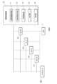
- FIG. 1 is a configuration diagram illustrating a configuration of an information processing system according to a first embodiment.
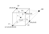
- 2 is a configuration diagram illustrating a positional relationship between a sensor and a tag according to the first embodiment;
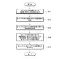
- FIG. 10 is a flowchart illustrating an example of an operation of an information processing device included in the information processing system according to the first embodiment.
- FIG. 11 is a configuration diagram illustrating a configuration of an information processing system according to a second embodiment.
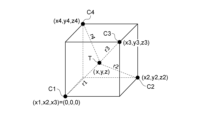
- 13 is a configuration diagram illustrating a positional relationship between a sensor and a tag according to a second embodiment.
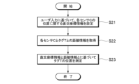
- FIG. 10 is a flowchart illustrating an example of an operation of an information processing device included in an information processing system according to the second embodiment.
- FIG. 13 is a configuration diagram illustrating a configuration of an information processing system according to a third embodiment.
- FIG. 13 is a configuration diagram illustrating a positional relationship between a sensor and a tag according to a third embodiment.
- 13 is a flowchart illustrating an example of an operation of an information processing device included in an information processing system according to the third embodiment.
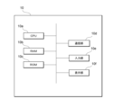
- FIG. 1 is a configuration diagram illustrating a physical configuration of an information processing apparatus according to an embodiment.
- the configuration of an information processing system according to the first embodiment will be described with reference to Fig. 1.
- the information processing system 100A shown in Fig. 1 includes, for example, an information processing device 10, a plurality of sensors MC, C1, C2, and C3, and a tag T.
- the multiple sensors shown in the figure are a master sensor MC and sensors C1 to C3. However, in the following description, when there is no need to distinguish between these sensors, some of the reference numerals will be omitted and they will simply be referred to as "sensor C.” When there is no need to distinguish between the information processing system 100A according to the first embodiment, the information processing system 100B according to the second embodiment, and the information processing system 100C according to the third embodiment, when there is no need to distinguish between them, some of the reference numerals will be omitted and they will simply be referred to as "information processing system 100."
- a worker with a tag T attached to a hand, arm, etc. measures the position of the tag T using a sensor 3 as the tag T moves as the worker performs work operations using parts, jigs, tools, etc.
- the sensor 3 is placed at a fixed position in the work space (predetermined space) including the tag T with respect to the worker performing the work operations.
- the information processing system 100A acquires arrangement information regarding the arrangement of four or more sensors C, and acquires distance information regarding the distance between at least one of the four or more sensors C and the tag T.
- the information processing system 100A measures the position of the tag T based on the arrangement information regarding the arrangement of the four or more sensors C and the distance information regarding the distance between the at least one sensor C and the tag T.
- the distance between the sensor C and the tag T in the information processing system 100A can be measured using a known ToA (Time of Arrive) method or the like. Specific details of the ToA method will be described later.
- the information processing system 100A can improve the measurement accuracy of the target position compared to conventional work evaluation systems that use wireless communication technology such as Wi-Fi.
- the tag T is associated with an "object.”
- the tag T when the tag T is attached to an object such as a worker's hand or arm, the tag T may be attached to the center of gravity of the object, or to a predetermined end of the object.
- the tag T is not limited to being attached to the worker.
- the tag T may be attached to a part, tool, etc. that the worker uses when performing work. In other words, the tag T may be attached to the object on which the work action is being performed.
- the components of the information processing system 100A are described below.
- Tag T is an electronic tag, and may be either a passive tag or an active tag.
- the sensor 3 measures the position of the tag T.
- the sensor 3 includes, for example, one or more antennas and a microcontroller.
- the microcomputer of the sensor 3 measures the distance, horizontal angle (Azimuth), and elevation angle (Elevation) to the tag T using radio waves of wireless communication exchanged between one or more antennas and the tag T.
- the microcomputer of the sensor 3 may also measure the distance, horizontal angle, and elevation angle to other sensors 3 using radio waves of wireless communication exchanged between one or more antennas and other sensors 3.
- the distance between the sensor 3 and at least one of the tag T and the other sensor 3 can be measured, for example, using the well-known ToA method.
- the horizontal angle and elevation angle between the sensor 3 and at least one of the tag T and other sensors 3 can be measured, for example, using the well-known AoA (Angle of Arrival) method.
- AoA Angle of Arrival
- multiple antennas of the receiver are used to measure the angle with the transmitter using the phase difference of the radio signal that occurs when the multiple antennas receive radio waves emitted from the transmitter.
- the sensor 3 transmits information regarding at least one of the distance, horizontal angle, and elevation angle measured for the tag T and/or the other sensor 3 to the information processing device 10.
- the information processing unit 10 is functionally configured to include a location information acquisition unit 11 (first acquisition unit), a distance information acquisition unit 12 (second acquisition unit), a position measurement unit 13 (measurement unit), an output unit 14, and a setting unit 15 (generation unit).
- a location information acquisition unit 11 first acquisition unit
- a distance information acquisition unit 12 second acquisition unit
- a position measurement unit 13 measurement unit
- an output unit 14 and a setting unit 15 (generation unit).
- the location information acquisition unit 11, the distance information acquisition unit 12, the position measurement unit 13, the output unit 14, and the setting unit 15 can be realized, for example, by the CPU 10a executing a program stored in the RAM 10b or ROM 10c of the information processing device 10 shown in FIG. 10, which will be described later.
- the setting unit 15 generates setting information related to three-dimensional coordinates, for example, based on input from an administrator (user) of the information processing system 100.
- the user may include an operator.
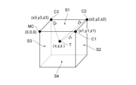
- FIG. 2 is a configuration diagram illustrating the positional relationship between the sensor and the tag according to the first embodiment.
- the manager or worker places the master sensor MC and the sensors C1 to C3 shown in FIG. 1 so that they are located on the same plane S1, which corresponds to the ceiling of the work area, for example.
- the tag T attached to the worker will be located below the ceiling.
- the setting unit 15 sets, for example, the positive or negative Z coordinate in the three-dimensional coordinates of the tag T (setting information). Note that, as described later, in the example of FIG.
- the Z coordinate in the three-dimensional coordinates of the tag T is set to "negative". This information on the positive or negative is used in the processing of the position measurement unit 13, which will be described later.
- the master sensor MC and the sensors C1 to C3 may be arranged on any plane, and are not limited to the plane S1 described above.
- the master sensor MC and the sensors C1 to C3 may be arranged on the plane S4, for example, which corresponds to the floor of the workplace.
- the tag T attached to the worker will be located above the floor.
- the setting unit 15 sets, for example, the positive or negative Z coordinate in the three-dimensional coordinate system of the tag T.
- the master sensor MC and the sensors C1 to C3 may be arranged on the plane S2 or S3, for example, which corresponds to the side wall of the workplace.
- the placement information acquisition unit 11 acquires placement information regarding the placement of four or more sensors C.
- the placement information acquisition unit 11 acquires distance information regarding the distance between one sensor C and each of the other sensors C among the four or more sensors C as placement information.
- each sensor C shown in FIG. 1 and FIG. 2 measures the distance between the sensors C using the ToA method.
- sensor C1 measures the distance between itself and other sensors C2, C3, and MC, and transmits the distance information to the information processing device 10. Similar processing is performed for the other sensors C.
- the distance information acquisition unit 12 acquires distance information regarding the distance between at least one of the four or more sensors C and the tag T.
- the sensor C1 measures the distance between itself and the tag T using the known ToA method, and transmits the distance information to the information processing device 10. Similar processing is performed for the other sensors C.
- the position measurement unit 13 measures the position of the tag T based on the placement information acquired by the placement information acquisition unit 11 and the distance information acquired by the distance information acquisition unit 12.
- the position measurement unit 13 calculates the positional relationship of each of the sensors MC, C1, C2, and C3 shown in FIG. 2 when the master sensor MC is set as the origin (0,0,0) from the distance between each two points (distance information as arrangement information). More specifically, the distance between each two points of the sensors MC, C1, C2, and C3 includes, for example, the distances corresponding to each of the four sides of the plane S1, and the distances corresponding to two diagonals based on the four vertices of the plane S1.
- the master sensor MC operates as a host sensor that manages time synchronization and data transfer between the sensors C.
- the position measurement unit 13 identifies the positions of the three points based on the calculated positional relationship and the positive/negative information set by the setting unit 15. That is, as shown in FIG. 2, the position measurement unit 13 identifies, for example, the three-dimensional coordinates (x1, y1, z1) of sensor C1, the three-dimensional coordinates (x2, y2, z2) of sensor C2, and the three-dimensional coordinates (x3, y3, z3) of sensor C3.
- the master sensor MC may be determined in advance by selecting one specific sensor from among the multiple sensors C as the master sensor. Also, when the three-dimensional coordinates of the other sensors are identified, the remaining sensor may be designated as the master sensor.
- the position measurement unit 13 identifies the coordinates of the tag T based on the distance between the tag T and three sensors (e.g., sensors C1, C2, and C3), the positive/negative information set by the setting unit 15, and the following formula 1.
- the position measurement unit 13 can calculate the three-dimensional coordinates (x, y, z) of tag T by substituting the three-dimensional coordinates (x1, y1, z1) of sensor C1, the three-dimensional coordinates (x2, y2, z2) of sensor C1, and the distances r1, r2, and r3 from the three-dimensional coordinates (x3, y3, z3) of sensor C1 to tag T into the above formula 1.
- the above formula 1 includes a square, and for example, for the Z coordinate, two values, positive and negative, are calculated, so the setting unit 15 needs to set positive and negative.
- the output unit 14 outputs the positional relationship between the four or more sensors C and the tag T based on the placement information acquired by the placement information acquisition unit 11, the position information regarding the position of the tag T measured by the position measurement unit 13, and the setting information generated by the setting unit 15. As shown in FIG. 2, the output unit 14 can display the positional relationship between the four sensors C and the tag T, for example, placed in a workplace, on the display unit 10f of the information processing device 10 shown in FIG. 10, which will be described later.
- the information processing device 10 sets positive/negative information regarding the Z coordinate in the three-dimensional coordinates of the tag T (S11).
- the information processing device 10 acquires distance information regarding the distance between each sensor C as placement information (S12).
- the information processing device 10 acquires distance information regarding the distance between each sensor C and the tag T (S13).
- the information processing device 10 measures the position of the tag T based on the distance information regarding the distance between each sensor C and the distance information regarding the distance between each sensor C and the tag T (S14).
- the information processing device 10 outputs the positional relationship between each sensor C and the tag T (S15).
- the information processing system 100A including the information processing device 10 according to the first embodiment acquires arrangement information regarding the arrangement of four or more sensors C, and acquires distance information regarding the distance between at least one of the four or more sensors C and the tag T.
- the information processing system 100A measures the position of the tag T based on the arrangement information regarding the arrangement of the four or more sensors C and the distance information regarding the distance between the at least one sensor C and the tag T. Therefore, when identifying the position of a tag in a work area, the information processing system 100A is able to improve the measurement accuracy of the target position compared to conventional work evaluation systems that use wireless communication technology such as Wi-Fi.
- the information processing system 100A calculates the positional relationship between the master sensor MC and the other sensors C1, C2, and C3 when the master sensor MC is set as the origin (0,0,0) from the distances between the three points, and identifies the positions of the three points based on the calculated positional relationship and the set positive/negative information. Therefore, even if the information processing system 100A can automatically obtain the three-dimensional coordinates of the sensors, it is easy for the user or worker to place each sensor in the workplace.
- the multiple sensors C are arranged so as not to be located on the same plane, which is different from the first embodiment in that the multiple sensors C are arranged so as to be located on the same plane.
- the following mainly describes the differences from the first embodiment.
- FIG. 4 is a configuration diagram illustrating the configuration of an information processing system according to the second embodiment.
- FIG. 5 is a configuration diagram illustrating the positional relationship between sensors and tags according to the second embodiment. As shown in FIG. 5, at least one sensor C among sensors C1, C2, C3, and C4 is arranged so as not to be located on the same plane. Note that the example arrangement of multiple sensors C shown in FIG. 5 is merely an example, and it is sufficient that at least one sensor C among the multiple sensors C is arranged so as not to be located on the same plane.
- the placement information acquisition unit 11 shown in FIG. 4 acquires placement information regarding the placement of four or more sensors C.
- the placement information acquisition unit 11 acquires position information regarding the positions of four or more sensors in a specified space as placement information.
- the worker or manager inputs three-dimensional coordinates for each of the placed sensors C.
- the setting unit 15 sets the three-dimensional coordinates for each of the placed sensors C in the information processing system 100B based on the input by the user.
- the placement information acquisition unit 11 acquires the three-dimensional coordinates for each of the placed sensors C set by the setting unit 15 as placement information.
- the distance information acquisition unit 12 acquires distance information regarding the distance between at least one of the four or more sensors C and the tag T.
- the sensor C1 measures the distance between itself and the tag T using the known ToA method, and transmits the distance information to the information processing device 10. Similar processing is performed for the other sensors C2, C3, and C4.
- the position measurement unit 13 identifies the coordinates of tag T based on the position information (placement information) of each sensor, the distance between tag T and each sensor, and the following formula 2.
- the position (orthogonal coordinate) information of each sensor is the three-dimensional coordinate of each sensor, and includes sensor C1 (x1, x2, x3), sensor C2 (x2, y2, z2), sensor C3 (x3, y3, z3), and sensor C4 (x4, y4, z4) shown in FIG. 5.
- the distance between tag T and each sensor includes r1, r2, r3, and r4 shown in FIG. 5.
- the position measurement unit 13 can calculate the three-dimensional coordinates (x, y, z) of tag T by substituting the three-dimensional coordinates (0, 0, 0) of sensor C1, the three-dimensional coordinates (x2, y2, z2) of sensor C2, the three-dimensional coordinates (x3, y3, z3) of sensor C3, and the distances r1, r2, r3, and r4 from the three-dimensional coordinates (x4, y4, z4) of sensor C4 to tag T into the above formula 2.
- the information processing device 10 sets orthogonal coordinate information (three-dimensional coordinates) regarding the position of each sensor C based on user input (S21).
- the information processing device 10 acquires distance information between each sensor C and the tag T (S22).
- the information processing device 10 measures the position of the tag T based on the orthogonal coordinate information and the distance information (S23).
- the information processing system 100B including the information processing device 10 according to the second embodiment acquires three-dimensional coordinate information relating to the positions of four or more sensors C in the workplace as position information when at least one sensor C of the four or more sensors C is not arranged on the same plane.
- the information processing system 100B acquires distance information relating to the distance between at least one sensor C of the four or more sensors C and the tag T, and measures the position of the tag T based on the position information and distance information. Therefore, even when at least one sensor C of the four or more sensors C is not arranged on the same plane, the information processing system 100B can improve the measurement accuracy of the position of the tag T by acquiring position information of each sensor C based on user input.
- the third embodiment differs from the first embodiment in that the multiple sensors C are arranged so as to be positioned on the same plane, in that the multiple sensors C are arranged so as not to be positioned on the same plane.
- the third embodiment differs from the second embodiment in that the information processing system 100 acquires the position information of each sensor C by automatically measuring it, in that the information processing system 100 acquires the position information of each sensor C based on the input of an operator or administrator (user). The following mainly describes the differences from the first and second embodiments.
- FIG. 7 is a configuration diagram illustrating the configuration of an information processing system according to the third embodiment.
- FIG. 8 is a configuration diagram illustrating the positional relationship between sensors and tags according to the third embodiment. As shown in FIG. 8, at least one sensor C among sensors C1, C2, C3, and C4 is arranged so as not to be located on the same plane. Note that the example arrangement of multiple sensors C shown in FIG. 8 is merely an example, and it is sufficient that at least one sensor C among multiple sensors C excluding the master sensor MC is arranged so as not to be located on the same plane.
- the setting unit 15 sets three-dimensional coordinates for the placed master sensor MC in the information processing system 100C based on input by the user.
- the placement information acquisition unit 11 may acquire the three-dimensional coordinates for the master sensor MC set by the setting unit 15.
- the placement information acquisition unit 11 acquires, as placement information, three-dimensional coordinate information regarding the positions of the other sensors C1, C2, C3, and C4 based on the position of one master sensor MC among the four or more sensors C.
- the master sensor MC acquires the distance between itself and each of the other sensors C1, C2, C3, and C4 using the AoA method.
- the master sensor MC also acquires the horizontal angle and elevation angle for each of the other sensors C1, C2, C3, and C4 using the master sensor MC as a reference, using the AoA method.
- the master sensor MC may transmit the measured distances, horizontal angles, and elevation angles for each of the other sensors C1, C2, C3, and C4 to the information processing device 10 as three-dimensional polar coordinate information.
- at least one of the sensors C1, C2, C3, and C4 may transmit its own polar coordinate information to the information processing device 10.
- the placement information acquisition unit 11 converts the three-dimensional polar coordinates of the measured distances, horizontal angles, and elevation angles for each of the sensors C1, C2, C3, and C4 into three-dimensional Cartesian coordinates. Note that the process of converting the three-dimensional polar coordinates into three-dimensional Cartesian coordinates may be performed by the position measurement unit 13.
- r1 be the distance between master sensor MC and sensor C2
- ⁇ be the horizontal angle with tag T
- ⁇ be the elevation angle with tag T.
- the three-dimensional polar coordinates of tag T which have these as elements, be expressed as (r, ⁇ , ⁇ ), and let the three-dimensional Cartesian coordinates of sensor C2 corresponding to these polar coordinates be expressed as (x2, y2, z2).
- equations for converting three-dimensional polar coordinates (r, ⁇ , ⁇ ) into three-dimensional Cartesian coordinates (x2, y2, z2) can be expressed by the following equations (3) to (5).
- the three-dimensional orthogonal coordinates of the other sensors C1, C3, and C4 can be expressed as (x1, x2, x3), (x3, y3, z3), and (x4, y4, z4), respectively, based on equations (3) to (5).
- the distance information acquisition unit 12 acquires distance information regarding the distance between at least one of the four or more sensors C and the tag T.
- the sensor C1 measures the distance between itself and the tag T using the known ToA method, and transmits the distance information to the information processing device 10. Similar processing is performed for the other sensors C2, C3, and C4.
- the position measurement unit 13 can calculate the three-dimensional coordinates (x, y, z) of tag T by substituting the three-dimensional coordinates (0, 0, 0) of sensor C1, the three-dimensional coordinates (x2, y2, z2) of sensor C2, the three-dimensional coordinates (x3, y3, z3) of sensor C3, and the distances r1, r2, r3, and r4 from the three-dimensional coordinates (x4, y4, z4) of sensor C4 to tag T into the above formula 2.
- the information processing device 10 acquires polar coordinate information relating to the position of each sensor C (S31).
- the information processing device 10 converts the polar coordinates of each sensor C into orthogonal coordinates (three-dimensional coordinates) (S32).
- the information processing device 10 acquires distance information between each sensor C and the tag T (S33).
- the information processing device 10 measures the position of the tag T based on the orthogonal coordinate information (three-dimensional coordinate information) and the distance information (S34).
- the information processing system 100C including the information processing device 10 according to the third embodiment acquires, as position information, three-dimensional coordinate information relating to the positions of the other sensors C1, C2, C3, and C4 based on the position of one master sensor MC among the four or more sensors C when at least one sensor C among the four or more sensors C is not arranged on the same plane.
- the information processing system 100C acquires distance information relating to the distance between at least one sensor C among the four or more sensors C and the tag T, and measures the position of the tag T based on the position information and the distance information.
- the information processing system 100B can improve the measurement accuracy of the position of the tag T by acquiring the position information of each sensor C1, C2, C3, and C4 by automatically measuring them.
- FIG. 10 is a diagram illustrating the physical configuration of an information processing device according to an embodiment.
- the information processing device 10 has a CPU (Central Processing Unit) 10a corresponding to a calculation unit, a RAM (Random Access Memory) 10b corresponding to a storage unit, a ROM (Read Only Memory) 10c corresponding to a storage unit, a communication unit 10d, an input unit 10e, and a display unit 10f. These components are connected to each other via a bus so that data can be transmitted and received.
- the information processing device 10 is configured by one computer, but the information processing device 10 may be realized by combining multiple computers.
- the configuration shown in FIG. 10 is an example, and the information processing device 10 may have other configurations than these, or may not have some of these configurations.
- the CPU 10a executes programs stored in the RAM 10b or ROM 10c, and functions as a control unit that performs various controls and calculates and processes data. For example, the CPU 10a executes a program (control program) for controlling the target device 20. The CPU 10a also receives various data from the input unit 10e and communication unit 10d, and displays the results of data calculations on the display unit 10f or stores them in the RAM 10b.
- RAM 10b is a storage unit in which data can be rewritten, and may be composed of, for example, a semiconductor memory element.
- RAM 10b may store, for example, a program executed by CPU 10a and data used by that program. Note that these are merely examples, and RAM 10b may store data other than these, or some of these data may not be stored.
- ROM 10c is a memory section from which data can be read, and may be configured, for example, with a semiconductor memory element. ROM 10c may store, for example, a control program or data that is not rewritten.
- the communication unit 10d is an interface that connects the information processing device 10 to other devices.
- the communication unit 10d may be connected to a communication network such as a LAN.
- the input unit 10e accepts data input from a user and may include, for example, a keyboard and a touch panel.
- the display unit 10f visually displays the results of calculations performed by the CPU 10a, and may be configured, for example, with an LCD (Liquid Crystal Display).
- the display unit 10f may display, for example, control signals and physical quantities in chronological order.
- the control program may be provided by being stored in a computer-readable storage medium such as RAM 10b or ROM 10c, or may be provided via a communication network connected by communication unit 10d.
- CPU 10a executes the control program to realize the various operations described above.
- these physical configurations are merely examples and do not necessarily have to be independent configurations.
- information processing device 10 may include an LSI (Large-Scale Integration) in which CPU 10a is integrated with RAM 10b and ROM 10c.
- An information processing system (100) for measuring a position of an object comprising: a tag (T) associated with said object; Four or more sensors (C) arranged in a predetermined space including the tag (T); An information processing device (10), The information processing device (10) A first acquisition unit that acquires arrangement information regarding an arrangement of the four or more sensors (C); a second acquisition unit that acquires distance information regarding a distance between at least one sensor (C) among the four or more sensors (C) and the tag (T); a measurement unit that measures the position of the tag (T) based on the arrangement information and the distance information, An information processing system (100).
- the four or more sensors (C) are arranged on the same plane,
- the first acquisition unit acquires distance information relating to a distance between one sensor (C) and each of the other sensors (C) among the four or more sensors (C) as the arrangement information.
- the position of the tag (T) is represented by three-dimensional coordinates, A generating unit that generates setting information related to the three-dimensional coordinates based on a user input; and an output unit (14) that outputs a positional relationship between the four or more sensors (C) and the tag (T) based on the acquired placement information, position information relating to the measured position of the tag (T), and the generated setting information.
- the information processing system (100) according to claim 1 or 2.
- the first acquisition unit acquires position information regarding positions of the four or more sensors (C) in the specified space as the arrangement information.
- the first acquisition unit acquires, as the arrangement information, position information regarding positions of the other sensors (C) based on a position of one sensor (C) among the four or more sensors (C); 2.
- the information processing system (100) according to claim 1.
- a first acquisition unit that acquires arrangement information regarding an arrangement of four or more sensors (C) arranged in a predetermined space, the sensors including a tag (T) associated with an object; a second acquisition unit that acquires distance information regarding a distance between at least one sensor (C) among the four or more sensors (C) and the tag (T); a measurement unit that measures the position of the tag (T) based on the arrangement information and the distance information, Information processing device (10).
- a first acquisition unit that acquires arrangement information regarding an arrangement of four or more sensors (C) arranged in a predetermined space, the sensors including a tag (T) associated with an object; a second acquisition unit that acquires distance information regarding a distance between at least one sensor (C) among the four or more sensors (C) and the tag (T); a measurement unit that measures the position of the tag (T) based on the arrangement information and the distance information;
- 10...information processing device 10a...CPU, 10b...RAM, 10c...ROM, 10d...communication unit, 10e...input unit, 10f...display unit, 11...location information acquisition unit, 12...distance information acquisition unit, 13...position measurement unit, 14...output unit, 15...setting unit, 100, 100A, 100B, 100C...information processing system, sensor...C, C1, C2, C3, C4, tag...T
Landscapes
- Physics & Mathematics (AREA)
- Engineering & Computer Science (AREA)
- General Physics & Mathematics (AREA)
- Radar, Positioning & Navigation (AREA)
- Remote Sensing (AREA)
- Position Fixing By Use Of Radio Waves (AREA)
- Length Measuring Devices With Unspecified Measuring Means (AREA)
- Radar Systems Or Details Thereof (AREA)
Abstract
対象の位置の測定精度を向上させることが可能な位置測定技術を提供すること。対象の位置を測定する情報処理システム100は、対象に関連づけられたタグTと、タグTを含む所定の空間に配置された4つ以上のセンサCと、情報処理装置10と、を備え、情報処理装置10は、4つ以上のセンサCの配置に関する配置情報を取得する第1取得部と、4つ以上のセンサCのうち少なくとも1つのセンサCとタグTとの距離に関する距離情報を取得する第2取得部と、配置情報と距離情報とに基づいてタグTの位置を測定する測定部と、を備える。
Description
本発明は、情報処理システム、情報処理装置、及び、プログラムに関する。
特許文献1には、作業領域において作業者の位置情報を取得可能な作業評価システムが開示されている。当該作業領域の四隅にはアンカーが設置されており、作業者が保持するタグと各アンカーとの間の距離を測定することで、作業領域におけるタグの位置を特定することができる。
特許文献1の記載の従来の作業評価システムは、作業領域におけるタグの位置を特定する際に、Wi-Fi等の無線通信技術を利用する。Wi-Fi等の無線通信技術を利用する測位技術は精度が低いため、従来の測定技術には改善の余地がある。
このような事情に鑑み、本発明は、対象の位置の測定精度を向上させることが可能な位置測定技術を提供することを目的とする。
本発明の一態様に係る情報処理システムは、対象の位置を測定する位置測定システムであって、対象に関連づけられたタグと、タグを含む所定の空間に配置された4つ以上のセンサと、情報処理装置と、を備え、情報処理装置は、4つ以上のセンサの配置に関する配置情報を取得する第1取得部と、4つ以上のセンサのうち少なくとも1つのセンサとタグとの距離に関する距離情報を取得する第2取得部と、配置情報と距離情報とに基づいてタグの位置を測定する測定部と、を備える。
上述した態様において、4つ以上のセンサは、同一平面上に配置され、第1取得部は、4つ以上のセンサのうち1つのセンサと他の各センサとの距離に関する距離情報を配置情報として取得してもよい。
上述した態様において、タグの位置は、三次元座標により表され、情報処理システムは、ユーザの入力に基づいて、三次元座標に関する設定情報を生成する生成部と、取得された配置情報と、測定されたタグの位置に関する位置情報と、生成された設定情報とに基づいて、4つ以上のセンサ、及び、タグの位置関係を出力する出力部と、をさらに備えてもよい。
上述した態様において、第1取得部は、4つ以上のセンサのうち少なくとも1つのセンサが同一平面上に配置されていない場合に、所定の空間における4つ以上のセンサの位置に関する位置情報を配置情報として取得してもよい。
上述した態様において、第1取得部は、4つ以上のセンサのうち少なくとも1つのセンサが同一平面上に配置されていない場合に、4つ以上のセンサのうち1つのセンサの位置に基づく他の各センサの位置に関する位置情報を配置情報として取得してもよい。
本発明の他の態様に係る情報処理装置は、対象に関連づけられたタグを含む所定の空間に配置された4つ以上のセンサの配置に関する配置情報を取得する第1取得部と、4つ以上のセンサのうち少なくとも1つのセンサとタグとの距離に関する距離情報を取得する第2取得部と、配置情報と距離情報とに基づいてタグの位置を測定する測定部と、を備える。
本発明の他の態様に係るプログラムは、コンピュータを、対象に関連づけられたタグを含む所定の空間に配置された4つ以上のセンサの配置に関する配置情報を取得する第1取得部と、4つ以上のセンサのうち少なくとも1つのセンサとタグとの距離に関する距離情報を取得する第2取得部と、配置情報と距離情報とに基づいてタグの位置を測定する測定部と、として機能させるためのプログラム。
本発明によれば、対象の位置の測定精度を向上させることが可能である。
添付図面を参照して、本発明の好適な実施形態について説明する。なお、各図において、同一の符号を付したものは、同一又は同様の構成を有する。ただし、図面は模式的なものであり、具体的な寸法などは以下の説明を照らし合わせて判断するべきものである。また、図面相互間においても互いの寸法の関係や比率が異なる部分が含まれていることは勿論である。
<第1実施形態>
図1を参照して、第1実施形態に係る情報処理システムの構成について説明する。図1に示す情報処理システム100Aは、例えば、情報処理装置10と、複数のセンサMC、C1、C2及びC3と、タグTと、を備える。
図1を参照して、第1実施形態に係る情報処理システムの構成について説明する。図1に示す情報処理システム100Aは、例えば、情報処理装置10と、複数のセンサMC、C1、C2及びC3と、タグTと、を備える。
複数のセンサとして、マスタセンサMC、及び、センサC1~C3を図示している。ただし、以下の説明において、これらセンサを区別することなく説明する場合には、符号を一部省略して、単に「センサC」と呼ぶ。情報処理システムに関して、第1実施形態に係る情報処理システム100A、第2実施形態に係る情報処理システム100B、及び、第3実施形態に係る情報処理システム100Cについて、区別することなく説明する場合には、符号を一部省略して、単に「情報処理システム100」と呼ぶ。
情報処理システム100の各構成要素を説明する前に、本発明が適用される場面の一例について説明する。実施形態に係るシステム100は、例えば、作業場において、手や腕など(対象)にタグTを取り付けた作業者が、部品や治工具などを用いる作業動作に伴って移動するタグTの位置をセンサ3で測定する。この場合、センサ3は、作業動作を行う作業者に対し、タグTを含む作業空間(所定の空間)において固定された位置に配置されることが好ましい。
より具体的には、情報処理システム100Aは、4つ以上のセンサCの配置に関する配置情報を取得し、4つ以上のセンサCのうち少なくとも1つのセンサCとタグTとの距離に関する距離情報を取得する。情報処理システム100Aは、4つ以上のセンサCの配置に関する配置情報と、少なくとも1つのセンサCとタグTとの距離に関する距離情報とに基づいてタグTの位置を測定する。例えば、情報処理システム100Aにおける、センサCとタグTとの距離の測定は、公知のToA(Time of Arrive)方式等を用いて測定可能である。ToA方式の具体的内容については後述する。
したがって、情報処理システム100Aは、作業領域におけるタグの位置を特定する際に、Wi-Fi等の無線通信技術を利用する従来の作業評価システムと比べて、対象の位置の測定精度を向上させることが可能である。
ここで、タグTは「対象」に関連づけられている。上記したように、タグTが作業者の手や腕などの対象に取り付けられる場合、タグTは、対象の重心に取り付けられてもよいし、対象の予め定められた一端に取り付けられてもよい。なお、タグTを取り付けるのは、作業者に限定されない。例えば、作業者が作業を行う際に用いる部品や治工具等にタグTが取り付けられてもよい。つまり、タグTは、作業動作を行う対象に取り付けられてもよい。
情報処理システム100Aの各構成要素について、以下に説明する。
タグTは、電子タグであり、パッシブタグであっても、アクティブタグであってもよい。
センサ3は、タグTの位置を測定する。センサ3は、例えば、一又は複数のアンテナと、マイクロコントローラ)とを備える。
センサ3のマイコンは、一又は複数のアンテナとタグTとの間でやり取りされる無線通信の電波を利用して、タグTとの距離、水平角(Azimuth)及び仰角(Elevation)を測定する。また、センサ3のマイコンは、一又は複数のアンテナと他のセンサ3との間でやり取りされる無線通信の電波を利用して、他のセンサ3との距離、水平角及び仰角を測定してもよい。
センサ3と、タグT及び他のセンサ3の少なくとも一方との距離は、例えば、公知のToA方式を用いて測定することができる。ToA方式では、送信機と受信機との間の電波の伝搬遅延時間を用いて、送信機と受信機との間の距離を測定する(距離=時間×光速)。
センサ3と、タグT及び他のセンサ3の少なくとも一方との水平角及び仰角は、例えば、公知のAoA(Angle of Arrive)方式を用いて測定することができる。AoA方式では、受信機の複数のアンテナを利用し、送信機から発信される電波を複数のアンテナで受信する際に生ずる電波信号の位相差を用いて送信機との角度を測定する。
センサ3は、タグT及び他のセンサ3の少なくとも一方に関して測定した距離、水平角及び仰角の少なくとも一つに関する情報を情報処理装置10に送信する。
情報処理部10は、機能的に、配置情報取得部11(第1取得部)と、距離情報取得部12(第2取得部)と、位置測定部13(測定部)と、出力部14と、設定部15(生成部)と、を含んで構成されている。なお、配置情報取得部11と、距離情報取得部12と、位置測定部13と、出力部14と、設定部15とは、例えば、後述する図10に示す情報処理装置10のRAM10bやROM10cに格納されているプログラムをCPU10aが実行したりすることにより実現することができる。
設定部15は、例えば情報処理システム100の管理者(ユーザ)の入力に基づいて、三次元座標に関する設定情報を生成する。なお、ユーザは、作業者を含んでもよい。
図2は、第1実施形態に係るセンサとタグの位置関係を例示する構成図である。図2に示すように、管理者又は作業者は、図1に示すマスタセンサMCと、センサC1~C3とを、例えば作業場の天井に対応する同一平面S1上に位置するように配置する。マスタセンサMCと、センサC1~C3とが作業場の天井に配置される場合、作業者に取り付けられるタグTは、天井よりも下に位置することになる。ユーザが、上記のような各センサCとタグTとの位置関係を入力すると、設定部15は、例えば、タグTの三次元座標におけるZ座標の正負(設定情報)を設定する。なお、後述のとおり、図2の例では、マスタセンサMCの三次元座標が(0,0,0)となるため、例えば、タグTの三次元座標におけるZ座標は「負」が設定される。この正負に関する情報が後述する位置測定部13の処理に利用される。
マスタセンサMCと、センサC1~C3とが配置される同一平面は任意であり、上記した平面S1には限定されない。マスタセンサMCと、センサC1~C3とは、例えば作業場の床に対応する平面S4に配置されてもよい。マスタセンサMCと、センサC1~C3とが作業場の床に配置される場合、作業者に取り付けられるタグTは、床よりも上に位置することになる。ユーザが、上記のような各センサCとタグTとの位置関係を入力すると、設定部15は、例えば、タグTの三次元座標におけるZ座標の正負を設定する。なお、マスタセンサMCと、センサC1~C3とは、例えば作業場の側壁に対応する平面S2又はS3に配置されてもよい。
図1に戻り、配置情報取得部11は、4つ以上のセンサCの配置に関する配置情報を取得する。配置情報取得部11は、4つ以上のセンサCのうち1つのセンサCと他の各センサCとの距離に関する距離情報を配置情報として取得する。
例えば、図1及び図2に示す各センサCは、互いのセンサC間の距離を、ToA方式を用いて測定する。例えば、センサC1は、他のセンサC2、C3、及び、MCとの間の距離を測定し、距離情報を情報処理装置10に送信する。他のセンサCについても同様の処理を実行する。
距離情報取得部12は、4つ以上のセンサCのうち少なくとも1つのセンサCとタグTとの距離に関する距離情報を取得する。例えば、センサC1は、タグTとの間の距離を公知のToA方式を用いて測定し、距離情報を情報処理装置10に送信する。他のセンサCについても同様の処理を実行する。
位置測定部13は、配置情報取得部11によって取得された配置情報と、距離情報取得部12によって取得された距離情報とに基づいてタグTの位置を測定する。
例えば、位置測定部13は、図2に示すセンサMC、C1、C2及びC3のうち各2点間の距離(配置情報としての距離情報)からマスタセンサMCを原点(0,0,0)としたときのそれぞれの位置関係を算出する。より具体的には、センサMC、C1、C2及びC3のうち各2点間の距離は、例えば平面S1の各4辺に対応する距離、及び、平面S1における4つの頂点に基づく2本の対角線に対応する距離を含む。マスタセンサMCは、各センサC間における時間同期及びデータ転送を司るホストセンサとして動作する。
位置測定部13は、算出された位置関係と、設定部15によって設定された正負情報とに基づいて3点の位置を特定する。つまり、図2に示すように、位置測定部13は、例えば、センサC1の三次元座標(x1,y1,z1)、センサC2の三次元座標(x2,y2,z2)、センサC3の三次元座標(x3,y3,z3)を特定する。
なお、マスタセンサMCは、あらかじめ,複数のセンサCのうち特定の1つのセンサをマスタセンサとして定めてもよい。また、他のセンサの三次元座標が特定された場合に、残った1つのセンサをマスタセンサとしてもよい。
例えば、位置測定部13は、タグTとセンサ3点(例えばセンサC1、C2及びC3)間との距離と、設定部15によって設定された正負情報と、以下の式1と、に基づいて、タグTの座標を特定する。
[式1]
(x1-x)^2+(y1-y)^2+(z1-z)^2=r1^2
(x2-x)^2+(y2-y)^2+(z2-z)^2=r2^2
(x3-x)^2+(y3-y)^2+(z3-z)^2=r3^2
(x1-x)^2+(y1-y)^2+(z1-z)^2=r1^2
(x2-x)^2+(y2-y)^2+(z2-z)^2=r2^2
(x3-x)^2+(y3-y)^2+(z3-z)^2=r3^2
ToA方式に基づいてタグTの三次元座標を算出するためには、少なくとも3つのセンサCからの情報が必要である。位置測定部13は、センサC1の三次元座標(x1,y1,z1)、センサC1の三次元座標(x2,y2,z2)、及び、センサC1の三次元座標(x3,y3,z3)からのタグTまでの各距離r1、r2及びr3を上記式1に代入することによって、タグTの三次元座標(x,y,z)を算出可能である。なお、上記式1は、二乗を含む式であり、例えばZ座標については、正負の二値が計算されるため、設定部15による正負の設定が必要である。
出力部14は、配置情報取得部11によって取得された配置情報と、位置測定部13によって測定されたタグTの位置に関する位置情報と、設定部15によって生成された設定情報とに基づいて、4つ以上のセンサC、及び、タグTの位置関係を出力する。図2に示すように、出力部14は、後述する図10に示す情報処理装置10の表示部10fにおいて、例えば作業場に配置された4つのセンサC、及び、タグTの位置関係を表示可能である。
図3を参照して、情報処理システム100Aに含まれる情報処理装置10の動作の一例について説明する。図3に示すように、情報処理装置10は、タグTの三次元座標におけるZ座標に関する正負情報を設定する(S11)。情報処理装置10は、各センサC間の距離に関する距離情報を配置情報として取得する(S12)。情報処理装置10は、各センサCとタグTとの間の距離に関する距離情報を取得する(S13)。情報処理装置10は、各センサC間の距離に関する距離情報と、各センサCとタグTとの間の距離に関する距離情報とに基づいてタグTの位置を測定する(S14)。情報処理装置10は、各センサC、及び、タグTの位置関係を出力する(S15)。
以上のとおり、第1実施形態に係る情報処理装置10を含む情報処理システム100Aは、4つ以上のセンサCの配置に関する配置情報を取得し、4つ以上のセンサCのうち少なくとも1つのセンサCとタグTとの距離に関する距離情報を取得する。情報処理システム100Aは、4つ以上のセンサCの配置に関する配置情報と、少なくとも1つのセンサCとタグTとの距離に関する距離情報とに基づいてタグTの位置を測定する。したがって、情報処理システム100Aは、作業領域におけるタグの位置を特定する際に、Wi-Fi等の無線通信技術を利用する従来の作業評価システムと比べて、対象の位置の測定精度を向上させることが可能である。
また、情報処理システム100Aは、マスタセンサMCと他のセンサC1、C2及びC3との3点間の距離からマスタセンサMCを原点(0,0,0)としたときのそれぞれの位置関係を算出し、算出された位置関係と、設定された正負情報とに基づいて3点の位置を特定する。したがって、情報処理システム100Aにおいて、センサの三次元座標を自動取得可能な場合であっても、ユーザ又は作業者によって、作業場において各センサを配置することが容易である。
<第2実施形態>
第2実施形態では、複数のセンサCを同一平面上に位置しないように配置する点で、複数のセンサCを同一平面上に位置するように配置する第1実施形態とは異なる。以下では、第1実施形態と異なる点について主に説明する。
第2実施形態では、複数のセンサCを同一平面上に位置しないように配置する点で、複数のセンサCを同一平面上に位置するように配置する第1実施形態とは異なる。以下では、第1実施形態と異なる点について主に説明する。
図4は、第2実施形態に係る情報処理システムの構成を例示する構成図である。図5は、第2実施形態に係るセンサとタグの位置関係を例示する構成図である。図5に示すように、センサC1、C2、C3及びC4のうち少なくとも1つのセンサCが同一平面上に位置しないように配置されている。なお、図5に示す複数のセンサCの配置例はあくまで一例であり、複数のセンサCのうち少なくとも1つのセンサCが同一平面上に位置しないように配置されていればよい。
図4に示す配置情報取得部11は、4つ以上のセンサCの配置に関する配置情報を取得する。例えば、配置情報取得部11は、所定の空間における4つ以上のセンサの位置に関する位置情報を配置情報として取得する。例えば、作業者が4つ以上のセンサCを作業場における所定の空間において配置する際に、作業者又は管理者(ユーザ)は、配置された複数のセンサCのそれぞれに関する三次元座標を入力する。設定部15は、ユーザによる入力に基づいて、配置された複数のセンサCのそれぞれに関する三次元座標を情報処理システム100Bにおいて設定する。配置情報取得部11は、設定部15によって設定された、複数のセンサCのそれぞれに関する三次元座標を配置情報として取得する。
距離情報取得部12は、4つ以上のセンサCのうち少なくとも1つのセンサCとタグTとの距離に関する距離情報を取得する。例えば、センサC1は、タグTとの間の距離を公知のToA方式を用いて測定し、距離情報を情報処理装置10に送信する。他のセンサC2、C3及びC4についても同様の処理を実行する。
位置測定部13は、各センサの位置情報(配置情報)と、タグTと各センサ間との距離と、以下の式2と、に基づいて、タグTの座標を特定する。例えば、各センサの位置(直交座標)情報は、各センサの三次元座標であり、図5に示す、センサC1(x1,x2,x3)、センサC2(x2,y2,z2)、センサC3(x3,y3,z3)、及び、センサC4(x4,y4,z4)を含む。また、例えば、タグTと各センサ間との距離は、図5に示すr1、r2、r3及びr4を含む。
[式2]
(x1-x)^2+(y1-y)^2+(z1-z)^2=r1^2
(x2-x)^2+(y2-y)^2+(z2-z)^2=r2^2
(x3-x)^2+(y3-y)^2+(z3-z)^2=r3^2
(x4-x)^2+(y4-y)^2+(z4-z)^2=r4^2
(x1-x)^2+(y1-y)^2+(z1-z)^2=r1^2
(x2-x)^2+(y2-y)^2+(z2-z)^2=r2^2
(x3-x)^2+(y3-y)^2+(z3-z)^2=r3^2
(x4-x)^2+(y4-y)^2+(z4-z)^2=r4^2
位置測定部13は、センサC1の三次元座標(0,0,0)、センサC2の三次元座標(x2,y2,z2)、センサC3の三次元座標(x3,y3,z3)、及び、センサC4の三次元座標(x4,y4,z4)からのタグTまでの各距離r1、r2、r3及びr4を上記式2に代入することによって、タグTの三次元座標(x,y,z)を算出可能である。
図6を参照して、第2実施形態に係る情報処理システム100Bに含まれる情報処理装置10の動作の一例を説明する。図6に示すように、情報処理装置10は、ユーザ入力に基づいて、各センサCの位置に関する直交座標情報(三次元座標)を設定する(S21)。情報処理装置10は、各センサCとタグTとの距離情報を取得する(S22)。情報処理装置10は、直交座標情報と距離情報とに基づいてタグTの位置を測定する(S23)。
以上のとおり、第2実施形態に係る情報処理装置10を含む情報処理システム100Bは、4つ以上のセンサCのうち少なくとも1つのセンサCが同一平面上に配置されていない場合に、作業場における4つ以上のセンサCの位置に関する三次元座標情報を配置情報として取得する。情報処理システム100Bは、4つ以上のセンサCのうち少なくとも1つのセンサCとタグTとの距離に関する距離情報を取得し、配置情報と距離情報とに基づいてタグTの位置を測定する。したがって、情報処理システム100Bは、4つ以上のセンサCのうち少なくとも1つのセンサCが同一平面上に配置されていない場合であっても、各センサCの位置情報をユーザの入力に基づいて取得することによって、タグTの位置の測定精度を向上させることが可能である。
<第3実施形態>
第3実施形態では、複数のセンサCを同一平面上に位置しないように配置する点で、複数のセンサCを同一平面上に位置するように配置する第1実施形態とは異なる。第3実施形態では、情報処理システム100が各センサCの位置情報を自動的に測定することによって取得する点で、情報処理システム100が各センサCの位置情報を作業者又は管理者(ユーザ)の入力に基づいて取得する第2実施形態とは異なる。以下では、第1実施形態及び第2実施形態と異なる点について主に説明する。
第3実施形態では、複数のセンサCを同一平面上に位置しないように配置する点で、複数のセンサCを同一平面上に位置するように配置する第1実施形態とは異なる。第3実施形態では、情報処理システム100が各センサCの位置情報を自動的に測定することによって取得する点で、情報処理システム100が各センサCの位置情報を作業者又は管理者(ユーザ)の入力に基づいて取得する第2実施形態とは異なる。以下では、第1実施形態及び第2実施形態と異なる点について主に説明する。
図7は、第3実施形態に係る情報処理システムの構成を例示する構成図である。図8は、第3実施形態に係るセンサとタグの位置関係を例示する構成図である。図8に示すように、センサC1、C2、C3及びC4のうち少なくとも1つのセンサCが同一平面上に位置しないように配置されている。なお、図8に示す複数のセンサCの配置例はあくまで一例であり、マスタセンサMCを除く複数のセンサCのうち少なくとも1つのセンサCが同一平面上に位置しないように配置されていればよい。
設定部15は、ユーザによる入力に基づいて、配置されたマスタセンサMCに関する三次元座標を情報処理システム100Cにおいて設定する。配置情報取得部11は、設定部15によって設定された、マスタセンサMCに関する三次元座標を取得してもよい。
配置情報取得部11は、4つ以上のセンサCのうち1つのマスタセンサMCの位置に基づく他の各センサC1、C2、C3及びC4の位置に関する三次元座標情報を配置情報として取得する。例えば、マスタセンサMCは、AoA方式を用いて、他のセンサC1、C2、C3及びC4のそれぞれとの間の距離を取得する。また、マスタセンサMCは、AoA方式を用いて、マスタセンサMCを基準として、他のセンサC1、C2、C3及びC4のそれぞれに対する水平角及び仰角を取得する。
マスタセンサMCは、他のセンサC1、C2、C3及びC4のそれぞれに関する、測定した距離、水平角、及び仰角を三次元の極座標情報として、情報処理装置10に送信してもよい。また、センサC1、C2、C3及びC4の少なくとも一つのセンサが、自らの極座標情報を情報処理装置10に送信してもよい。
配置情報取得部11は、センサC1、C2、C3及びC4のそれぞれに関する、測定された距離、水平角、及び仰角を三次元の極座標を、三次元の直交座標に変換する。なお、三次元の極座標を、三次元の直交座標に変換する処理は、位置測定部13が実行してもよい。
ここで、例えばマスタセンサMCとセンサC2間の距離をr1とし、タグTとの水平角をθとし、タグTとの仰角をφとし、これらを要素とするタグTの三次元極座標を(r、θ、φ)と表し、その極座標に対応するセンサC2の三次元直交座標を(x2、y2、z2)と表すことにする。
上記の条件において、三次元の極座標(r、θ、φ)を、三次元の直交座標(x2、y2、z2)に変換する式は、以下の式(3)乃至式(5)により表すことができる。
[式3]
x2=r×cos(φ)cos(θ)
[式4]
y2=r×cos(φ)sin(θ)
[式5]
z2=r×sin(φ)
x2=r×cos(φ)cos(θ)
[式4]
y2=r×cos(φ)sin(θ)
[式5]
z2=r×sin(φ)
同様に、他のセンサC1、C3及びC4の三次元直交座標についても、それぞれ、式(3)乃至式(5)に基づいて、(x1、x2、x3)、(x3、y3、z3)及び(x4、y4、z4)と表すことが可能である。
距離情報取得部12は、4つ以上のセンサCのうち少なくとも1つのセンサCとタグTとの距離に関する距離情報を取得する。例えば、センサC1は、タグTとの間の距離を公知のToA方式を用いて測定し、距離情報を情報処理装置10に送信する。他のセンサC2、C3及びC4についても同様の処理を実行する。
位置測定部13は、センサC1の三次元座標(0,0,0)、センサC2の三次元座標(x2,y2,z2)、センサC3の三次元座標(x3,y3,z3)、及び、センサC4の三次元座標(x4,y4,z4)からのタグTまでの各距離r1、r2、r3及びr4を上記式2に代入することによって、タグTの三次元座標(x,y,z)を算出可能である。
図9を参照して、第3実施形態に係る情報処理システム100Cに含まれる情報処理装置10の動作の一例を説明する。図9に示すように、情報処理装置10は、各センサCの位置に関する極座標情報を取得する(S31)。情報処理装置10は、各センサCの極座標を直交座標(三次元座標)に変換する(S32)。情報処理装置10は、各センサCとタグTとの距離情報を取得する(S33)。情報処理装置10は、直交座標情報(三次元座標情報)と距離情報とに基づいてタグTの位置を測定する(S34)。
以上のとおり、第3実施形態に係る情報処理装置10を含む情報処理システム100Cは、4つ以上のセンサCのうち少なくとも1つのセンサCが同一平面上に配置されていない場合に、4つ以上のセンサCのうち1つのマスタセンサMCの位置に基づく他の各センサC1、C2、C3及びC4の位置に関する三次元座標情報を配置情報として取得する。情報処理システム100Cは、4つ以上のセンサCのうち少なくとも1つのセンサCとタグTとの距離に関する距離情報を取得し、配置情報と距離情報とに基づいてタグTの位置を測定する。したがって、情報処理システム100Bは、4つ以上のセンサCのうち少なくとも1つのセンサCが同一平面上に配置されていない場合であっても、各センサC1、C2、C3及びC4の位置情報を自動的に測定することによって取得することによって、タグTの位置の測定精度を向上させることが可能である。
図10は、実施形態に係る情報処理装置の物理的な構成を例示する図である。情報処理装置10は、演算部に相当するCPU(Central Processing Unit)10aと、記憶部に相当するRAM(Random Access Memory)10bと、記憶部に相当するROM(Read Only Memory)10cと、通信部10dと、入力部10eと、表示部10fと、を有する。これらの各構成は、バスを介して相互にデータ送受信可能に接続される。なお、本例では情報処理装置10が一台のコンピュータで構成される場合について説明するが、情報処理装置10は、複数のコンピュータが組み合わされて実現されてもよい。また、図10に示す構成は一例であり、情報処理装置10はこれら以外の構成を有してもよいし、これらの構成のうち一部を有さなくてもよい。
CPU10aは、RAM10b又はROM10cに記憶されたプログラムを実行し、各種の制御やデータの演算及び加工を行う制御部として機能する。例えば、CPU10aは、対象装置20を制御するためのプログラム(制御プログラム)を実行する。また、CPU10aは、入力部10eや通信部10dから種々のデータを受け取り、データの演算結果を表示部10fに表示したり、RAM10bに格納したりする。
RAM10bは、記憶部のうちデータの書き換えが可能なものであり、例えば半導体記憶素子で構成されてよい。RAM10bは、例えばCPU10aが実行するプログラム、そのプログラムで用いるデータを記憶してよい。なお、これらは例示であって、RAM10bには、これら以外のデータが記憶されてもよいし、これらの一部が記憶されなくてもよい。
ROM10cは、記憶部のうちデータの読み出しが可能なものであり、例えば半導体記憶素子で構成されてよい。ROM10cは、例えば制御プログラムや、書き換えが行われないデータを記憶してよい。
通信部10dは、情報処理装置10を他の機器に接続するインターフェースである。通信部10dは、LAN等の通信ネットワークに接続されてよい。
入力部10eは、ユーザからデータの入力を受け付けるものであり、例えば、キーボード及びタッチパネルを含んでよい。
表示部10fは、CPU10aによる演算結果を視覚的に表示するものであり、例えば、LCD(Liquid Crystal Display)により構成されてよい。表示部10fは、例えば、制御信号や物理量を時系列で表示してよい。
制御プログラムは、RAM10bやROM10c等のコンピュータによって読み取り可能な記憶媒体に記憶されて提供されてもよいし、通信部10dにより接続される通信ネットワークを介して提供されてもよい。情報処理装置10では、CPU10aが制御プログラムを実行することにより、上記で説明した様々な動作が実現される。なお、これらの物理的な構成は例示であって、必ずしも独立した構成でなくてもよい。例えば、情報処理装置10は、CPU10aとRAM10bやROM10cが一体化したLSI(Large-Scale Integration)を備えてもよい。
以上説明した各実施形態は、あらゆる点において本発明の例示に過ぎない。本発明の範囲を逸脱することなく種々の改良や変形を行うことができることは言うまでもない。つまり、本発明の実施にあたって、実施形態に応じた具体的構成が適宜採用されてもよい。また、上述した各実施形態は、本発明の理解を容易にするためのものであり、本発明を限定して解釈するためのものではない。各実施形態が備える各要素並びにその配置、材料、条件、形状及びサイズ等は、例示したものに限定されるわけではなく適宜変更することができる。
[付記]
本実施形態における態様は、以下のような開示を含む。
本実施形態における態様は、以下のような開示を含む。
(付記1)
対象の位置を測定する情報処理システム(100)であって、
前記対象に関連づけられたタグ(T)と、
前記タグ(T)を含む所定の空間に配置された4つ以上のセンサ(C)と、
情報処理装置(10)と、を備え、
前記情報処理装置(10)は、
前記4つ以上のセンサ(C)の配置に関する配置情報を取得する第1取得部と、
前記4つ以上のセンサ(C)のうち少なくとも1つのセンサ(C)と前記タグ(T)との距離に関する距離情報を取得する第2取得部と、
前記配置情報と前記距離情報とに基づいて前記タグ(T)の位置を測定する測定部と、を備える、
情報処理システム(100)。
対象の位置を測定する情報処理システム(100)であって、
前記対象に関連づけられたタグ(T)と、
前記タグ(T)を含む所定の空間に配置された4つ以上のセンサ(C)と、
情報処理装置(10)と、を備え、
前記情報処理装置(10)は、
前記4つ以上のセンサ(C)の配置に関する配置情報を取得する第1取得部と、
前記4つ以上のセンサ(C)のうち少なくとも1つのセンサ(C)と前記タグ(T)との距離に関する距離情報を取得する第2取得部と、
前記配置情報と前記距離情報とに基づいて前記タグ(T)の位置を測定する測定部と、を備える、
情報処理システム(100)。
(付記2)
前記4つ以上のセンサ(C)は、同一平面上に配置され、
前記第1取得部は、前記4つ以上のセンサ(C)のうち1つのセンサ(C)と他の各センサ(C)との距離に関する距離情報を前記配.置情報として取得する、
付記1記載の情報処理システム(100)。
前記4つ以上のセンサ(C)は、同一平面上に配置され、
前記第1取得部は、前記4つ以上のセンサ(C)のうち1つのセンサ(C)と他の各センサ(C)との距離に関する距離情報を前記配.置情報として取得する、
付記1記載の情報処理システム(100)。
(付記3)
前記タグ(T)の位置は、三次元座標により表され、
ユーザの入力に基づいて、前記三次元座標に関する設定情報を生成する生成部と、
取得された前記配置情報と、測定された前記タグ(T)の位置に関する位置情報と、生成された前記設定情報とに基づいて、前記4つ以上のセンサ(C)、及び、前記タグ(T)の位置関係を出力する出力部(14)と、をさらに備える、
付記1又は2記載の情報処理システム(100)。
前記タグ(T)の位置は、三次元座標により表され、
ユーザの入力に基づいて、前記三次元座標に関する設定情報を生成する生成部と、
取得された前記配置情報と、測定された前記タグ(T)の位置に関する位置情報と、生成された前記設定情報とに基づいて、前記4つ以上のセンサ(C)、及び、前記タグ(T)の位置関係を出力する出力部(14)と、をさらに備える、
付記1又は2記載の情報処理システム(100)。
(付記4)
前記第1取得部は、前記4つ以上のセンサ(C)のうち少なくとも1つのセンサ(C)が同一平面上に配置されていない場合に、前記所定の空間における前記4つ以上のセンサ(C)の位置に関する位置情報を前記配置情報として取得する、
付記1に記載の情報処理システム(100)。
前記第1取得部は、前記4つ以上のセンサ(C)のうち少なくとも1つのセンサ(C)が同一平面上に配置されていない場合に、前記所定の空間における前記4つ以上のセンサ(C)の位置に関する位置情報を前記配置情報として取得する、
付記1に記載の情報処理システム(100)。
(付記5)
前記第1取得部は、前記4つ以上のセンサ(C)のうち少なくとも1つのセンサ(C)が同一平面上に配置されていない場合に、前記4つ以上のセンサ(C)のうち1つのセンサ(C)の位置に基づく他の各センサ(C)の位置に関する位置情報を前記配置情報として取得する、
付記1に記載の情報処理システム(100)。
前記第1取得部は、前記4つ以上のセンサ(C)のうち少なくとも1つのセンサ(C)が同一平面上に配置されていない場合に、前記4つ以上のセンサ(C)のうち1つのセンサ(C)の位置に基づく他の各センサ(C)の位置に関する位置情報を前記配置情報として取得する、
付記1に記載の情報処理システム(100)。
(付記6)
対象に関連づけられたタグ(T)を含む所定の空間に配置された4つ以上のセンサ(C)の配置に関する配置情報を取得する第1取得部と、
前記4つ以上のセンサ(C)のうち少なくとも1つのセンサ(C)と前記タグ(T)との距離に関する距離情報を取得する第2取得部と、
前記配置情報と前記距離情報とに基づいて前記タグ(T)の位置を測定する測定部と、を備える、
情報処理装置(10)。
対象に関連づけられたタグ(T)を含む所定の空間に配置された4つ以上のセンサ(C)の配置に関する配置情報を取得する第1取得部と、
前記4つ以上のセンサ(C)のうち少なくとも1つのセンサ(C)と前記タグ(T)との距離に関する距離情報を取得する第2取得部と、
前記配置情報と前記距離情報とに基づいて前記タグ(T)の位置を測定する測定部と、を備える、
情報処理装置(10)。
(付記7)
コンピュータを、
対象に関連づけられたタグ(T)を含む所定の空間に配置された4つ以上のセンサ(C)の配置に関する配置情報を取得する第1取得部と、
前記4つ以上のセンサ(C)のうち少なくとも1つのセンサ(C)と前記タグ(T)との距離に関する距離情報を取得する第2取得部と、
前記配置情報と前記距離情報とに基づいて前記タグ(T)の位置を測定する測定部と、
として機能させるためのプログラム。
コンピュータを、
対象に関連づけられたタグ(T)を含む所定の空間に配置された4つ以上のセンサ(C)の配置に関する配置情報を取得する第1取得部と、
前記4つ以上のセンサ(C)のうち少なくとも1つのセンサ(C)と前記タグ(T)との距離に関する距離情報を取得する第2取得部と、
前記配置情報と前記距離情報とに基づいて前記タグ(T)の位置を測定する測定部と、
として機能させるためのプログラム。
10…情報処理装置、10a…CPU、10b…RAM、10c…ROM、10d…通信部、10e…入力部、10f…表示部、11…配置情報取得部、12…距離情報取得部、13…位置測定部、14…出力部、15…設定部、100,100A,100B,100C…情報処理システム、センサ…C,C1,C2,C3,C4、タグ…T
Claims (7)
- 対象の位置を測定する情報処理システムであって、
前記対象に関連づけられたタグと、
前記タグを含む所定の空間に配置された4つ以上のセンサと、
情報処理装置と、を備え、
前記情報処理装置は、
前記4つ以上のセンサの配置に関する配置情報を取得する第1取得部と、
前記4つ以上のセンサのうち少なくとも1つのセンサと前記タグとの距離に関する距離情報を取得する第2取得部と、
前記配置情報と前記距離情報とに基づいて前記タグの位置を測定する測定部と、を備える、
情報処理システム。 - 前記4つ以上のセンサは、同一平面上に配置され、
前記第1取得部は、前記4つ以上のセンサのうち1つのセンサと他の各センサとの距離に関する距離情報を前記配置情報として取得する、
請求項1に記載の情報処理システム。 - 前記タグの位置は、三次元座標により表され、
ユーザの入力に基づいて、前記三次元座標に関する設定情報を生成する生成部と、
取得された前記配置情報と、測定された前記タグの位置に関する位置情報と、生成された前記設定情報とに基づいて、前記4つ以上のセンサ、及び、前記タグの位置関係を出力する出力部と、をさらに備える、
請求項1又は2に記載の情報処理システム。 - 前記第1取得部は、前記4つ以上のセンサのうち少なくとも1つのセンサが同一平面上に配置されていない場合に、前記所定の空間における前記4つ以上のセンサの位置に関する位置情報を前記配置情報として取得する、
請求項1に記載の情報処理システム。 - 前記第1取得部は、前記4つ以上のセンサのうち少なくとも1つのセンサが同一平面上に配置されていない場合に、前記4つ以上のセンサのうち1つのセンサの位置に基づく他の各センサの位置に関する位置情報を前記配置情報として取得する、
請求項1に記載の情報処理システム。 - 対象に関連づけられたタグを含む所定の空間に配置された4つ以上のセンサの配置に関する配置情報を取得する第1取得部と、
前記4つ以上のセンサのうち少なくとも1つのセンサと前記タグとの距離に関する距離情報を取得する第2取得部と、
前記配置情報と前記距離情報とに基づいて前記タグの位置を測定する測定部と、を備える、
情報処理装置。 - コンピュータを、
対象に関連づけられたタグを含む所定の空間に配置された4つ以上のセンサの配置に関する配置情報を取得する第1取得部と、
前記4つ以上のセンサのうち少なくとも1つのセンサと前記タグとの距離に関する距離情報を取得する第2取得部と、
前記配置情報と前記距離情報とに基づいて前記タグの位置を測定する測定部と、
として機能させるためのプログラム。
Applications Claiming Priority (2)
| Application Number | Priority Date | Filing Date | Title |
|---|---|---|---|
| JP2023-039414 | 2023-03-14 | ||
| JP2023039414A JP2024129974A (ja) | 2023-03-14 | 2023-03-14 | 情報処理システム、情報処理装置、及び、プログラム |
Publications (1)
| Publication Number | Publication Date |
|---|---|
| WO2024190263A1 true WO2024190263A1 (ja) | 2024-09-19 |
Family
ID=92755323
Family Applications (1)
| Application Number | Title | Priority Date | Filing Date |
|---|---|---|---|
| PCT/JP2024/005436 Ceased WO2024190263A1 (ja) | 2023-03-14 | 2024-02-16 | 情報処理システム、情報処理装置、及び、プログラム |
Country Status (3)
| Country | Link |
|---|---|
| JP (1) | JP2024129974A (ja) |
| TW (1) | TW202437186A (ja) |
| WO (1) | WO2024190263A1 (ja) |
Citations (4)
| Publication number | Priority date | Publication date | Assignee | Title |
|---|---|---|---|---|
| US20070076638A1 (en) * | 2005-10-05 | 2007-04-05 | Honeywell International Inc. | Localization for low cost sensor network |
| JP2009237870A (ja) * | 2008-03-27 | 2009-10-15 | Brother Ind Ltd | 保護者管理システム |
| JP2010228896A (ja) * | 2009-03-30 | 2010-10-14 | Fujitsu Frontech Ltd | 検出システム及び検出方法 |
| JP2022019718A (ja) * | 2016-06-03 | 2022-01-27 | ロシックス・インコーポレイテッド | 複数の通信経路が存在する中での正確な無線周波数位置推定のためのシステムおよび方法 |
-
2023
- 2023-03-14 JP JP2023039414A patent/JP2024129974A/ja active Pending
-
2024
- 2024-02-16 WO PCT/JP2024/005436 patent/WO2024190263A1/ja not_active Ceased
- 2024-02-21 TW TW113106050A patent/TW202437186A/zh unknown
Patent Citations (4)
| Publication number | Priority date | Publication date | Assignee | Title |
|---|---|---|---|---|
| US20070076638A1 (en) * | 2005-10-05 | 2007-04-05 | Honeywell International Inc. | Localization for low cost sensor network |
| JP2009237870A (ja) * | 2008-03-27 | 2009-10-15 | Brother Ind Ltd | 保護者管理システム |
| JP2010228896A (ja) * | 2009-03-30 | 2010-10-14 | Fujitsu Frontech Ltd | 検出システム及び検出方法 |
| JP2022019718A (ja) * | 2016-06-03 | 2022-01-27 | ロシックス・インコーポレイテッド | 複数の通信経路が存在する中での正確な無線周波数位置推定のためのシステムおよび方法 |
Also Published As
| Publication number | Publication date |
|---|---|
| TW202437186A (zh) | 2024-09-16 |
| JP2024129974A (ja) | 2024-09-30 |
Similar Documents
| Publication | Publication Date | Title |
|---|---|---|
| US20240152663A1 (en) | Acoustic positioning transmitter and receiver system and method | |
| US20190281573A1 (en) | Location Correction Apparatus and Method in a Real-Time Locating System | |
| US10627475B2 (en) | Pose estimation using radio frequency identification (RFID) tags | |
| CN106646380B (zh) | 一种多基站空间定位方法和系统 | |
| US10282574B1 (en) | Location correction apparatus and method in a real-time locating system | |
| US20210048526A1 (en) | Ad hoc positioning of mobile devices using near ultrasound signals | |
| US11864152B2 (en) | Location determination using acoustic-contextual data | |
| JP2013110606A (ja) | 端末装置、位置特定方法、及びプログラム | |
| US10378898B2 (en) | Methods and systems for use in indicating directions for direction finding systems | |
| EP2664942B1 (en) | Methods and systems for use in selecting targets for direction finding systems | |
| JP2024129974A (ja) | 情報処理システム、情報処理装置、及び、プログラム | |
| JP6091476B2 (ja) | 設備機器操作装置、設備機器操作方法およびプログラム | |
| JP2020203368A (ja) | ロボットシステム | |
| US20200057134A1 (en) | Systems, methods, and devices for verification of position estimation using an orientation sensor | |
| CN110753303B (zh) | 一种基于多传感器融合的服务机器人室内定位系统及方法 | |
| JP4794416B2 (ja) | 目標位置標定装置 | |
| JP7512711B2 (ja) | システム | |
| Divya et al. | Indoor Navigation Using Ultra Wide Band | |
| US8712433B1 (en) | Methods and systems for use in tracking targets for direction finding systems | |
| AU3905000A (en) | Method for creating a user-selectable coordinate frame | |
| US11485024B2 (en) | Determination of object position by aligned device placement | |
| JP2025108138A (ja) | 情報処理システム | |
| CN114708406A (zh) | 一种基于物联网技术的建筑施工方法及系统 | |
| TW201818094A (zh) | 定位方法及其相關裝置 |
Legal Events
| Date | Code | Title | Description |
|---|---|---|---|
| 121 | Ep: the epo has been informed by wipo that ep was designated in this application |
Ref document number: 24770378 Country of ref document: EP Kind code of ref document: A1 |
|
| NENP | Non-entry into the national phase |
Ref country code: DE |
|
| 122 | Ep: pct application non-entry in european phase |
Ref document number: 24770378 Country of ref document: EP Kind code of ref document: A1 |