WO2024190243A1 - 電源装置及び電動工具 - Google Patents
電源装置及び電動工具 Download PDFInfo
- Publication number
- WO2024190243A1 WO2024190243A1 PCT/JP2024/004977 JP2024004977W WO2024190243A1 WO 2024190243 A1 WO2024190243 A1 WO 2024190243A1 JP 2024004977 W JP2024004977 W JP 2024004977W WO 2024190243 A1 WO2024190243 A1 WO 2024190243A1
- Authority
- WO
- WIPO (PCT)
- Prior art keywords
- power supply
- supply device
- tool body
- tool
- control
- Prior art date
- Legal status (The legal status is an assumption and is not a legal conclusion. Google has not performed a legal analysis and makes no representation as to the accuracy of the status listed.)
- Ceased
Links
Images







Classifications
-
- B—PERFORMING OPERATIONS; TRANSPORTING
- B25—HAND TOOLS; PORTABLE POWER-DRIVEN TOOLS; MANIPULATORS
- B25F—COMBINATION OR MULTI-PURPOSE TOOLS NOT OTHERWISE PROVIDED FOR; DETAILS OR COMPONENTS OF PORTABLE POWER-DRIVEN TOOLS NOT PARTICULARLY RELATED TO THE OPERATIONS PERFORMED AND NOT OTHERWISE PROVIDED FOR
- B25F5/00—Details or components of portable power-driven tools not particularly related to the operations performed and not otherwise provided for
Definitions
- This disclosure relates to power tools.
- Patent document 1 describes technology related to power tools.
- a power supply device and an electric power tool are disclosed.
- the power supply device is connectable to each of a plurality of types of electric power tool bodies.
- the power supply device includes a control circuit and a power supply unit.
- the control circuit controls a connection tool body, which is an electric power tool body connected to the power supply device.
- the power supply unit supplies power to the connection tool body and the control circuit.
- the control circuit stores a plurality of control methods corresponding to each of the plurality of types of electric power tool bodies.
- the control circuit identifies the type of the connection tool body and controls the connection tool body with a control method corresponding to the identified type from among the plurality of control methods.
- the power supply device is a power supply device connected to the power tool body.
- the power supply device includes a communication circuit, a control circuit, and a power supply unit.
- the communication circuit receives a first control program stored in a device external to the power supply device.
- the control circuit controls the power tool body based on the first control program received by the communication circuit.
- the power supply unit outputs power to the power tool body and the control circuit.
- the power tool includes the power supply device and a power tool body to which the power supply device is connected.
- FIG. 1 is a schematic diagram illustrating an example of a configuration of a power tool.
- 1 is a schematic diagram showing an example of a state in which a power supply device can be connected to a plurality of types of power tool bodies;
- 1 is a schematic diagram mainly showing an example of a circuit configuration of a power tool;
- FIG. 2 is a schematic diagram showing an example of a configuration of a microcomputer.
- FIG. 1 is a schematic diagram illustrating an example of a configuration of a power tool.
- FIG. 1 is a schematic diagram illustrating an example of a configuration of a power tool.
- FIG. 1 is a schematic diagram illustrating an example of a configuration of a power tool.
- FIG. 1 is a schematic diagram illustrating an example of a configuration of a power tool.
- FIG. 1 is a schematic diagram illustrating an example of a configuration of a power tool.
- FIG. 1 is a schematic diagram illustrating an example of a configuration of a power tool.
- FIG. 1 is a schematic diagram illustrating an example of a configuration of a power tool.
- FIG. 2 is a schematic diagram showing an example of a configuration of a microcomputer.
- FIG. 11 is a schematic diagram for explaining an example of a method for updating a control program in a power supply device.
- FIG. 1 is a schematic diagram illustrating an example of a configuration of a power tool.
- FIG. 1 is a schematic diagram illustrating an example of a configuration of a power tool.
- FIG. 1 is a schematic diagram illustrating an example of a configuration of a power tool.
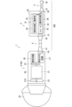
- FIG. 1 is a schematic diagram showing an example of a power tool 1.
- the power tool 1 includes, for example, a power tool body 2 including a motor 21, a power supply unit 3 that supplies power to the power tool body 2, a connection cable 4 that connects the power tool body 2 and the power supply unit 3 to each other, and a connection cable 5 that connects the power supply unit 3 to a commercial power source.
- the power supply unit 3 can be connected to each of multiple types of power tool bodies 2.
- the power supply unit 3 can be connected to each of multiple types of power tool bodies 2 via the connection cable 4, for example. Because the power supply unit 3 can be connected to multiple types of power tool bodies 2, a user can share the power supply unit 3 between multiple types of power tool bodies 2.
- the power tool 1 shown in FIG. 1 is, for example, a handheld disc grinder.
- the power tool 1 may be a handheld power tool other than a disc grinder.
- the power tool 1 may be an impact driver, a driver drill, a circular saw, a reciprocating saw, or a polisher.
- the power tool body 2 may be simply referred to as the tool body 2.
- the multiple types of tool body 2 to which the power supply device 3 can be connected may include a disc grinder tool body 2 as shown in FIG. 1, an impact driver tool body 2, a drill driver tool body 2, a circular saw tool body 2, a reciprocating saw tool body 2, or a polisher tool body 2.
- the tool body 2 connected to the power supply device 3 may be referred to as the connected tool body 2.
- the example of the tool body 2 shown in FIG. 1 may be referred to specifically as the tool body 2A.
- the tool body 2A includes, for example, a housing 20 that contains multiple parts and is held by the user.
- the housing 20 contains a motor 21, a sensor board 22, a cooling fan 23, a connector 24, a communication circuit 26, a resistive voltage divider circuit 27, and the like.
- the motor 21 is, for example, a brushless DC motor.
- the tool body 2A includes a drive unit driven by the motor 21.
- the drive unit includes, for example, a gear unit housed in the housing 20 and a disk-shaped grinding wheel 25 exposed from the housing 20.
- the gear unit transmits the rotation of the motor 21 to the grinding wheel 25 by reducing the rotational speed.
- the motor 21 is capable of rotating the grinding wheel 25 via the gear unit.
- the power tool 1 is capable of performing grinding, cutting, polishing, etc. by rotating the grinding wheel 25.
- the motor 21 is driven by the power supply unit 3.
- the sensor board 22 is capable of detecting the rotational position of the motor 21. More specifically, the sensor board 22 is capable of detecting the rotational position of a rotor provided in the motor 21.
- the cooling fan 23 is connected to the rotating shaft 210 of the motor 21. The cooling fan 23 rotates as the rotating shaft 210 rotates. When the cooling fan 23 rotates, air is taken into the housing 20 through an air intake provided at the rear of the housing 20. The air taken in through the air intake cools the motor 21 and other components inside the housing 20, and is then exhausted to the outside of the housing 20 through an exhaust port provided at the front of the housing 20.
- the connector 24 is partially exposed from the housing 20, and a connection cable 4 is connected to the connector 24.
- the communication circuit 26 is capable of communicating with a communication circuit 36 included in the power supply device 3.
- the communication circuit 26 performs wireless communication with the communication circuit 36, for example.
- the communication circuit 26 performs wireless communication in accordance with Bluetooth (registered trademark), for example.
- Bluetooth registered trademark
- the wireless method in which the communication circuit 26 complies is not limited to Bluetooth.
- the wireless method in which the communication circuit 26 complies may be Wi-Fi, ZigBee (registered trademark), or NFC (Near Field Communication).
- the resistive voltage divider circuit 27 divides a predetermined voltage to generate a resistive divided voltage V1 (see FIG. 3 described below). As described below, the value of the resistive divided voltage V1 is used as identification information indicating the type of the tool body 2. This identification information can also be said to be information for identifying the type of the tool body 2. The identification information indicating the type of the tool body 2 indicates the value of the resistive divided voltage V1. Hereinafter, simply referring to identification information means identification information indicating the type of the tool body 2.
- Each of the multiple types of tool bodies 2 to which the power supply device 3 can be connected includes, for example, at least a motor 21, a drive unit driven by the motor 21, a connector 24, a communication circuit 26, and a resistor voltage divider circuit 27.
- the drive unit is capable of machining an object by being driven by the motor 21.
- the power supply unit 3 is a separate device from the tool body 2.
- the power supply unit 3 has a housing 30 that houses multiple components.
- the housing 30 houses a circuit board 31, a connector 37, and a connector 38.
- the circuit board 31 includes a board 32, a power supply unit 33, a control circuit 34, an inverter 35, and a communication circuit 36 mounted on the board 32.
- the power supply unit 33 can supply the power required by the connection tool main body 2 to the connection tool main body 2.
- the power supply unit 33 can also supply power to circuits other than the power supply unit 33 mounted on the circuit board 31.
- the power supply unit 33 converts, for example, AC voltage supplied from a commercial power source into DC voltage and supplies the generated DC voltage to the inverter 35 and the control circuit 34.
- the power supply unit 33 can also be called a power supply circuit.
- the inverter 35 can drive the motor 21 provided in the connection tool main body 2.
- the inverter 35 can also be called a drive circuit that drives the motor 21, and the control circuit 34 can control the inverter 35.
- the control circuit 34 can control the motor 21 of the connection tool main body 2 by controlling the inverter 35. It can also be said that the control circuit 34 can control the motor 21 of the connection tool main body 2 through the inverter 35.
- connection cable 4 is connected to the connector 37.
- the connection cable 4 extends from the housing 30 of the power supply device 3 to the housing 20 of the tool body 2.
- the length of the connection cable 4 is, for example, several tens of centimeters to several meters. The length of the connection cable 4 is not limited to this.
- connection cable 4 One end of the connection cable 4 is provided with a connector 41 that is connected to the connector 24 of the tool body 2.
- the other end of the connection cable 4 is provided with a connector 42 that is connected to the connector 37 of the power supply device 3.
- One end of the connection cable 5 is provided with a connector 51 that is connected to the connector 38 of the power supply device 3.
- the other end of the connection cable 5 is provided with a connector 52 that is connected to an outlet that supplies AC voltage from a commercial power source.
- the connector 52 is sometimes called a power plug.
- connection cable 4 is detachable from the tool body 2.
- the connector 41 of the connection cable 4 is detachable from the connector 24 of the tool body 2.
- the other end of the connection cable 4 is detachable from the power supply device 3.
- the connector 42 of the connection cable 4 is detachable from the connector 37 inside the housing 30.
- connection cable 5 is detachable from the power supply unit 3.
- the connector 51 of the connection cable 5 is detachable from the connector 38 in the housing 30.
- the connector 52 of the connection cable 5 is detachable from the outlet. It can be said that the power tool 1 is equipped with a cable-equipped power supply unit 300 that includes the power supply unit 3 and the connection cables 4 and 5.
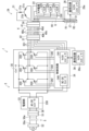
- FIG. 3 is a diagram mainly showing an example of the circuit configuration of the power tool 1.
- a single-phase AC voltage from a commercial power source is supplied to the connector 52 of the connection cable 5.
- the AC voltage is supplied to the connector 38 of the power supply device 3 through the connection cable 5.
- the connection cable 5 has two signal lines 50a.
- An AC voltage with an effective value of, for example, 100V is supplied to the connector 38.
- the AC voltage supplied to the connector 38 is supplied to the power supply unit 33.
- the power supply unit 33 includes an AC-DC converter 330.
- the AC-DC converter 330 converts the AC voltage into a DC voltage and outputs it.
- the AC-DC converter 330 is composed of, for example, a rectifier circuit, and has a diode and a capacitor.
- the AC-DC converter 330 outputs a DC voltage of, for example, about 140 V.
- the DC voltage output by the AC-DC converter 330 is supplied to the control circuit 34.
- the DC voltage output by the AC-DC converter 330 is supplied to the inverter 35 as a power source.
- the inverter 35 includes, for example, six switching elements 350.
- the switching elements 350 are, for example, semiconductor elements.
- a FET Field effect transistor
- the switching elements 350 may be an IGBT (Insulated Gate Bipolar Transistor) or other semiconductor elements.
- IGBT Insulated Gate Bipolar Transistor
- three switching circuits, each of which has two switching elements 350 connected in series, are connected in parallel. In each switching circuit, the voltage at the connection point of the two switching elements is supplied to the motor 21 as a drive signal 351.
- the drive signal 351 can also be referred to as a drive voltage 351.
- the three drive signals 351 generated by the inverter 35 are supplied to the motor 21 via the connector 37 of the power supply unit 3, the connection cable 4, and the connector 24 of the tool body 2.
- the connection cable 4 has three signal lines 40a that transmit the three drive signals 351 from the power supply unit 3 to the tool body 2.
- the motor 21 is, for example, a three-phase motor, and has a U-phase coil 21a, a V-phase coil 21b, and a W-phase coil 21c.
- the three drive signals 351 are supplied to the U-phase coil 21a, the V-phase coil 21b, and the W-phase coil 21c, respectively.
- the sensor board 22 provided in the tool body 2 includes, for example, three sensors 220. Each sensor 220 detects the rotational position of the motor 21. The sensor board 22 can also be said to configure a sensor circuit that detects the rotational position of the motor 21.
- the three sensors 220 are arranged, for example, at 120 degree intervals along the rotational direction of the motor 21.
- the sensors 220 may be, for example, Hall sensors or other types of sensors.
- the output signal (in other words, position detection signal) 230 of each sensor 220 is supplied to the connector 24.
- the three output signals 230 supplied to the connector 24 are supplied to the control circuit 34 through the connection cable 4 and the connector 37 of the power supply device 3.
- the connection cable 4 includes three signal lines 40d that transmit the output signals 230 of the three sensors 220 from the tool body 2 to the power supply device 3.
- the output signal 230 of the sensor 220 may be referred to as the sensor signal 230.
- the control circuit 34 includes, for example, a microcomputer 341 and a DC-DC converter 340.
- the DC-DC converter 340 steps down and outputs the DC voltage supplied from the AC-DC converter 330.
- the DC-DC converter 340 can be said to be a step-down circuit.
- the DC-DC converter 340 generates power for the microcomputer 341.
- the DC-DC converter 340 also generates power for specific circuits in the connection tool body 2.
- the specific circuits include the sensor board 22 (in other words, the sensor circuit) and the communication circuit 26.
- the power for the specific circuits generated by the DC-DC converter 340 (for example, +5V) is supplied to each sensor 220 and the communication circuit 26 of the sensor board 22 via the connector 37, the connection cable 4, and the connector 24.
- the connection cable 4 includes a signal line 40b that transmits a positive power source for a specific circuit (e.g., a positive potential V0) from the power supply device 3 to the tool body 2, and a signal line 40c that transmits a negative power source for a specific circuit (e.g., a ground potential G) from the power supply device 3 to the tool body 2.
- the connection cable 4 includes eight signal lines.
- the DC-DC converter 340 may be provided in the power supply unit 33.
- the resistive voltage divider circuit 27 divides the voltage between the positive potential V0 transmitted by the signal line 40b and the ground potential G transmitted by the signal line 40c to generate a resistive divided voltage V1 and outputs it to the communication circuit 26.
- the resistive voltage divider circuit 27 includes, for example, resistive elements R1 and R2 connected in series with each other between the positive potential V0 and the ground potential G.
- the resistive voltage divider circuit 27 outputs the voltage between the potential at the connection point of the resistive elements R1 and R2 and the ground potential G as the resistive divided voltage V1 to the communication circuit 26.
- the value of the resistive divided voltage V1 can be changed by changing the value of at least one of the resistive elements R1 and R2.
- the value of the resistor divided voltage V1 is used as identification information indicating the type of the tool body 2.
- the values of the resistor divided voltage V1 differ between multiple types of tool bodies 2.
- the value of the resistor divided voltage V1 can be said to be a value specific to the type of tool body 2.
- the value of the resistor divided voltage V1 in the tool body 2 of a disc grinder is set to 4.5 V
- the value of the resistor divided voltage V1 in the tool body 2 of an impact driver is set to 4 V
- the value of the resistor divided voltage V1 in the tool body 2 of a drill driver is set to 3.5 V
- the value of the resistor divided voltage V1 in the tool body 2 of a circular saw is set to 3 V
- the value of the resistor divided voltage V1 in the tool body 2 of a reciprocating saw is set to 2.5 V
- the value of the resistor divided voltage V1 in the tool body 2 of a polisher is set to 2 V.
- the value of the resistor divided voltage V1 is not limited to this.
- the communication circuit 26 of the connection tool main body 2 transmits the value of the resistive divided voltage V1 as identification information to the communication circuit 36 of the power supply device 3.
- the communication circuit 26 includes, for example, a wireless circuit and a microcomputer 26a.
- the microcomputer 26a includes, for example, an A/D converter. This A/D converter converts the value of the resistive divided voltage V1 into digital data.
- the wireless circuit included in the communication circuit 26 wirelessly transmits the digital data identification information to the communication circuit 36.
- the configuration of the microcomputer 26a may be the same as, for example, the configuration example of the microcomputer 341 shown in FIG. 4 described later.
- the communication circuit 36 of the power supply device 3 includes, for example, a wireless circuit and a microcomputer 36a.
- the wireless circuit in the communication circuit 36 receives the identification information wirelessly transmitted from the communication circuit 26.
- the microcomputer 36a in the communication circuit 36 then outputs the identification information received by the wireless circuit to the microcomputer 341.
- the configuration of the microcomputer 36a may be the same as, for example, the configuration example of the microcomputer 341 shown in FIG. 4, which will be described later.
- the microcomputer 341 is capable of controlling the connecting tool body 2.
- the microcomputer 341 can also be considered a computer device.
- the microcomputer 341 can also be considered a control circuit that controls the connecting tool body 2.
- the microcomputer 341 can also be considered a control circuit that can control each of the multiple types of tool bodies 2.
- the microcomputer 341 controls the rotation of the motor 21 of the connection tool main body 2, for example, by controlling the inverter 35 based on the three sensor signals 230 from the sensor board 22.
- the microcomputer 341 controls the voltage of the control terminal of each switching element 350 of the inverter 35 based on the three sensor signals 230 to control the on/off state of each switching element 350.
- the inverter 35 supplies appropriate drive signals 351 (in other words, drive voltages 351) to each of the U-phase coil 21a, V-phase coil 21b, and W-phase coil 21c of the motor 21, thereby controlling the rotation of the motor 21.
- the microcomputer 341 generates six control signals 342 and supplies the six generated control signals 342 to the control terminals of the six switching elements 350, respectively. How the six control signals 342 are generated determines how the motor 21 of the connection tool main body 2 is controlled.
- the control method for the connecting tool body 2, specifically the control method for the motor 21 of the connecting tool body 2 is determined by six control signals 342.
- Microcomputer 341 includes at least one processor to provide control and processing power to perform various functions, as described in more detail below.
- the at least one processor may be implemented as a single integrated circuit (IC) or as multiple communicatively connected integrated circuits ICs and/or discrete circuits.
- the at least one processor may be implemented according to various known techniques.
- a processor includes one or more circuits or units configured to perform one or more data computation procedures or processes, e.g., by executing instructions stored in associated memory.
- a processor may be firmware (e.g., discrete logic components) configured to perform one or more data computation procedures or processes.
- the processor may include one or more processors, controllers, microcomputers, microcontrollers, application specific integrated circuits (ASICs), digital signal processors, programmable logic devices, field programmable gate arrays, or any combination of these devices or configurations, or other known devices and configurations, to perform the functions described below.
- ASICs application specific integrated circuits
- digital signal processors programmable logic devices, field programmable gate arrays, or any combination of these devices or configurations, or other known devices and configurations, to perform the functions described below.
- FIG. 4 is a schematic diagram showing an example of the configuration of the microcomputer 341.
- the microcomputer 341 includes, for example, a CPU (Central Processing Unit) 400 as a processor.
- the microcomputer 341 also includes a memory unit 410 and a peripheral circuit 450.
- the memory unit 410 may include a non-transitory recording medium readable by the CPU 400, such as a ROM (Read Only Memory) and a RAM (Random Access Memory).
- the memory unit 410 can also be referred to as, for example, a memory circuit.
- the memory unit 410 stores, for example, a program 420 for controlling the operation of the microcomputer 341.
- the various functions of the CPU 400 are realized, for example, by the CPU 400 executing the program 420 in the memory unit 410.
- the peripheral circuit 450 may include, for example, a plurality of output ports and a plurality of input ports.
- the peripheral circuit 450 may also include an A/D converter that converts analog values into digital data.
- the peripheral circuit 450 may also include a communication circuit that performs wired communication, or a communication circuit that performs wireless communication.
- the peripheral circuit 450 acquires three sensor signals 230 from the sensor board 22 output by the communication circuit 26 and outputs them to the CPU 400.
- the CPU 400 controls the peripheral circuit 450 based on the three sensor signals 230, causing the peripheral circuit 450 to output six control signals 342 to the inverter 35.
- the CPU 400 controls the inverter 35 through the peripheral circuit 450, and can control the motor 21 of the connection tool main body 2 by controlling the inverter 35.
- the CPU 400 can also be said to be a control circuit that controls the connection tool main body 2.
- the CPU 400 can also be said to be a control circuit that can control each of the multiple types of tool main bodies 2.
- the program 420 in the storage unit 410 includes, for example, a control program 430 for controlling multiple types of tool bodies 2 to which the power supply device 3 is connected. Multiple types of control methods corresponding to the multiple types of tool bodies 2 are described in the control program 430. It can also be said that the microcomputer 341 stores multiple types of control methods corresponding to the multiple types of tool bodies 2.
- the CPU 400 is capable of controlling multiple types of tool bodies 2 based on the control program 430. In other words, the CPU 400 is capable of controlling multiple types of tool bodies 2 by executing the control program 430.
- the control program 430 describes, for example, a control method that corresponds to the tool body 2 of a disc grinder, a control method that corresponds to the tool body 2 of an impact driver, a control method that corresponds to the tool body 2 of a drill driver, a control method that corresponds to the tool body 2 of a circular saw, a control method that corresponds to the tool body 2 of a reciprocating saw, and a control method that corresponds to the tool body 2 of a polisher.
- the CPU 400 executes the control program 430 to control the connection tool body 2 using one of a number of control methods that correspond to the type of the connection tool body 2.
- the CPU 400 executing the control program 430 outputs each control signal 342 supplied to the inverter 35 to the peripheral circuit 450 so that the motor 21 of the connection tool body 2 is controlled using a control method that corresponds to the type of the connection tool body 2.
- the microcomputer 341 executing the control program 430 can also be said to generate each control signal 342 so that the motor 21 of the connection tool body 2 is controlled using a control method that corresponds to the type of the connection tool body 2.
- the appropriate rotation speed of the motor 21, the rotation direction of the motor 21, and the appropriate acceleration/deceleration method of the rotation of the motor 21 differ depending on the type of the tool body 2.
- the CPU 400 can appropriately control the motor 21 of the connection tool body 2 by controlling the motor 21 of the connection tool body 2 by a control method corresponding to the type of the connection tool body 2 from among the multiple control methods. In other words, the CPU 400 can control the motor 21 so that the rotation speed, rotation direction, and acceleration/deceleration method of the motor 21 of the connection tool body 2 correspond to the type of the connection tool body 2.
- the control program 430 includes, for example, a common module in which control contents common to multiple types of tool bodies 2 are described, and multiple unique modules in which control contents unique to each of the multiple types of tool bodies 2 are described.
- the CPU 400 can control the motor 21 of the connection tool body 2 by a control method corresponding to the type of the connection tool body 2 by executing a combination of the common module and the unique module corresponding to the type of the connection tool body 2.
- the power supply device 3 When the power supply device 3 is connected to the tool body 2, power is supplied from the control circuit 34 to the communication circuit 26 of the connection tool body 2 through the connection cable 4.
- the communication circuit 26 wirelessly transmits identification information to the communication circuit 36 of the power supply device 3.
- the communication circuit 36 inputs the received identification information to the microcomputer 341.
- the identification information input to the microcomputer 341 is input to the CPU 400 through the peripheral circuit 450.
- the CPU 400 identifies the type of the connection tool body 2 based on the identification information. Then, the CPU 400 controls the motor 21 of the connection tool body 2 using a control method according to the identified type based on the control program 430.
- the control circuit 34 stores a plurality of control methods corresponding to the plurality of types of electric power tool bodies. The control circuit 34 then identifies the type of the connected tool body and controls the connected tool body with a control method corresponding to the identified type from among the plurality of control methods stored. This allows the power supply device 3 to appropriately control the connected tool body 2. For example, as in the example of FIG. 1, when a disc grinder tool body 2 is connected to the power supply device 3, the power supply device 3 can control the disc grinder tool body 2 with a control method corresponding to the disc grinder tool body 2. Also, when an impact driver tool body 2 is connected to the power supply device 3, the power supply device 3 can control the impact driver with a control method corresponding to the impact driver tool body 2.
- control circuit 34 when the control circuit 34 acquires identification information indicating the type of the connection tool body 2 and identifies the type of the connection tool body 2, the control circuit 34 can easily identify the type of the connection tool body 2.
- the identification information indicates the value of the resistive voltage divider voltage V1 generated by the resistive voltage divider circuit 27 as in this example
- the identification information of multiple types of tool bodies 2 can be easily set by adjusting the value of the resistive element of the resistive voltage divider circuit 27.
- the power supply device 3 can easily obtain the identification information of the connecting tool main body 2.
- FIG. 5 is a schematic diagram showing an example of a state in which the communication circuit 26 and the communication circuit 36 are connected by wire.
- the communication circuit 26 and the communication circuit 36 communicate with each other by wire, at least one signal line 40z connecting the communication circuit 26 and the communication circuit 36 is provided in the connection cable 4.
- the communication circuit 26 and the communication circuit 36 exchange signals with each other using at least one signal line 40z.
- the microcomputer 26a of the communication circuit 26 and the microcomputer 36a of the communication circuit 36 may communicate with each other by wire.
- the standard of the wired communication between the communication circuit 26 and the communication circuit 36 may be, for example, SPI (Serial Peripheral Interface), I 2 C (Inter Integrated Circuit), or UART (Universal Asynchronous Receiver/Transmitter).
- connection cable 4 when the communication circuits 26 and 36 communicate with each other via a wire, it is necessary to provide at least one signal line 40z in the connection cable 4. In contrast, when the communication circuits 26 and 36 are wireless communication circuits, as in the example of FIG. 3, the number of signal lines included in the connection cable 4 can be reduced.
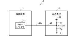
- the resistive divided voltage V1 output by the resistive voltage divider circuit 27 may be transmitted to the power supply device 3 by a signal line 40y provided on the connection cable 4, as shown in FIG. 6.
- the resistive divided voltage V1 transmitted to the power supply device 3 by the signal line 40y is input to, for example, the microcomputer 341.
- an A/D converter provided in the peripheral circuit 450 converts the value of the resistive divided voltage V1 into digital data and outputs it to the CPU 400. This allows the CPU 400 to obtain the identification information.
- the communication circuits 26 and 36 are not required.
- both resistive elements R1 and R2 of the resistive voltage divider circuit 27 are provided in the tool body 2, but one of resistive elements R1 and R2 may be provided in the tool body 2 and the other of resistive elements R1 and R2 may be provided in the power supply device 3. In this case, the communication circuits 26 and 36 are not required.
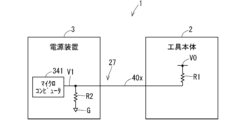
- FIG. 7 is a schematic diagram showing an example of a state in which the resistive element R1 is provided in the tool body 2 and the resistive element R2 is provided in the power supply unit 3.
- a signal line 40x is provided in the connection cable 4, connecting the resistive element R1 on the tool body 2 side and the resistive element R2 on the power supply unit 3 side.
- the resistive divided voltage V1 is then input to the microcomputer 341.
- an A/D converter provided in the peripheral circuit 450 converts the value of the resistive divided voltage V1 into digital data and inputs it to the CPU 40.
- FIG. 8 is a schematic diagram showing an example of a state in which the resistive element R2 is provided in the tool body 2 and the resistive element R1 is provided in the power supply unit 3.
- a signal line 40w is provided in the connection cable 4, connecting the resistive element R1 on the power supply unit 3 side and the resistive element R2 on the tool body 2 side.
- the resistive divided voltage V1 is then input to the microcomputer 341.
- an A/D converter provided in the peripheral circuit 450 converts the value of the resistive divided voltage V1 into digital data and inputs it to the CPU 40.
- the microcomputer 26a of the communication circuit 26 may obtain the identification information of the connected tool body 2 based on the resistive divided voltage V1, instead of using the resistive divided voltage V1 as the identification information as it is.
- a plurality of different ranges for the resistive divided voltage V1 are set for each of a plurality of types of tool bodies 2.
- a first range, a second range, a third range, a fourth range, a fifth range, and a sixth range of the resistive divided voltage V1 are set for each of the tool bodies 2 of a disc grinder, the tool body 2 of an impact driver, the tool body 2 of a drill driver, the tool body 2 of a circular saw, the tool body 2 of a reciprocating saw, and the tool body 2 of a polisher.
- the first range, the second range, the third range, the fourth range, the fifth range, and the sixth range are different from each other.
- the first range is set, for example, to a range from 4.4V to 4.5V.
- digital data indicating the type of the tool body 2 to which the range is set is stored as identification information for each of the above ranges of the resistive divided voltage V1.
- the microcomputer 26a identifies the range to which the A/D converted resistive divided voltage V1 belongs among the multiple ranges of the resistive divided voltage V1. Then, the microcomputer 26a reads out identification information indicating the type of the tool body 2 to which the identified range is set from the storage unit, and uses the read identification information as identification information of the connected tool body 2.
- the microcomputer 26a reads out identification information of the tool body 2 of the disc grinder to which the first range is set from the storage unit, and uses it as identification information of the tool body 2 to which the microcomputer 26a belongs.
- the identification information is acquired in this way, even if there is an error in the resistive divided voltage V1, the connected tool body 2 can appropriately transmit identification information according to its own type to the power supply device 3.
- the amount of data of the identification information can be reduced compared to when the resistive divided voltage V1 is used as the identification information as it is.
- the identification information may be 3-bit digital data.
- the 3-bit data "000" may be used as the identification information for the tool body 2 of a disc grinder
- the 3-bit data "001" may be used as the identification information for the tool body 2 of an impact driver.
- the identification information may also be obtained without using the resistive voltage divider V1.
- identification information corresponding to the type of tool body 2 to which the microcomputer 26a belongs may be pre-stored in the microcomputer 26a of the communication circuit 26, and the communication circuit 26 may transmit the identification information stored in the microcomputer 26a to the power supply device 3.
- the communication circuit 26 may transmit the identification information pre-stored in the microcomputer 26a to the communication circuit 36 of the power supply device 3 wirelessly as in the example of FIG. 3, or may transmit it via a wire as in FIG. 5. If identification information corresponding to the type of tool body 2 is pre-stored in the tool body 2, the resistive voltage divider circuit 27 is not necessary.
- the power supply unit 33 supplies power to the communication circuits 26 and 36, but as shown in FIG. 9, a battery 260 that supplies power to the communication circuit 26 may be provided in the tool body 2.
- the battery 260 may be a secondary battery or a primary battery.
- a battery 360 that supplies power to the communication circuit 36 may be provided in the power supply device 3.
- the battery 360 may be a secondary battery or a primary battery. If the battery 260 is provided, the battery 360 does not have to be provided, and if the battery 360 is provided, the battery 260 does not have to be provided.
- the program 420 in the storage unit 410 of the microcomputer 341 includes a control program 430 in which multiple types of control methods are described, but it may also include multiple control programs 440 in which multiple types of control methods are each individually described.
- Figure 10 is a schematic diagram showing an example of the configuration of the microcomputer 341 in this case.
- the CPU 400 controls the tool connection body 2 based on one of the multiple control programs 440 that corresponds to the type of tool connection body 2.
- the CPU 400 can control the tool connection body 2 using a control method that corresponds to the type of tool connection body 2 by executing one of the multiple control programs 440 in the storage unit 410, which describes a control method that corresponds to the type of tool connection body 2.
- the communication circuit 36 is provided separately from the microcomputer 341, but the communication circuit provided in the peripheral circuit 450 of the microcomputer 341 may function as the communication circuit 36.
- the microcomputer 341 may receive information transmitted wirelessly or via a wire from the communication circuit 26.
- the microcomputer 26a of the communication circuit 26 and the microcomputer 341 may communicate with each other wirelessly or via a wire.
- ⁇ Regarding control program updates> When the number of types of tool bodies 2 to which the power supply device 3 can be connected increases, it is necessary to update the control program 430 in the power supply device 3.
- the power supply device 3 acquires the latest control program 430, for example, from an external device that stores the latest control program 430.
- the power supply device 3 then updates the control program 430 in the storage unit 410 with the acquired latest control program 430. This allows the control program 430 in the power supply device 3 to be appropriately updated.
- a specific example of a method for updating the control program 430 in the power supply device 3 will be described below.
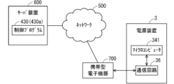
- FIG. 11 is a schematic diagram for explaining an example of a method for updating the control program 430 in the power supply device 3.
- the latest control program 430 (also referred to as the latest program 430a) is stored in a server device 600 connected to a network 500 including the Internet. If there is an increase in the types of tool bodies 2 to which the power supply device 3 can be connected, a latest program 430a corresponding to the increase is created and stored in the server device 600. For example, if the types of tool bodies 2 to which the power supply device 3 can be connected increase from five to six, a latest program 430a describing the control method for the six types of tool bodies 2 is created and stored in the server device 600.
- the server device 600 may be, for example, a cloud server.
- the power supply device 3 is capable of acquiring the latest program 430a stored in the server device 600.
- the power supply device 3 can obtain the latest program 430a from the server device 600 through the portable electronic device 700 connected to the network 500, for example.
- the portable electronic device 700 obtains the latest program 430a from the server device 600 through the network 500.
- the portable electronic device 700 then transmits the obtained latest program 430a to the communication circuit 36 of the power supply device 3.
- the communication circuit 36 of the power supply device 3 can directly communicate with the portable electronic device 700.
- the communication circuit 36 may perform wireless communication with the portable electronic device 700, or may perform wired communication.
- the portable electronic device 700 may be, for example, a mobile phone such as a smartphone, a tablet terminal, a notebook personal computer, or a wearable terminal.
- Each of the server device 600 and the portable electronic device 700 includes, for example, a microcomputer and a communication circuit.
- the microcomputers included in the server device 600 and the portable electronic device 700 may have a configuration similar to that of the microcomputer 341 included in the power supply device 3.
- the microcomputer of the server device 600 stores the latest program 430a and the version number (also called the latest version number) of the latest program 430a in correspondence with each other.
- the communication circuit of the server device 600 is capable of communicating with the network 500.
- the communication circuit of the server device 600 transmits the latest program 430a and the latest version number to the communication circuit of the portable electronic device 700 via the network 500.
- the communication circuit of the portable electronic device 700 is capable of communicating with the network 500 and is also capable of communicating with the communication circuit 36 of the power supply device 3.
- the communication circuit of the portable electronic device 700 receives the latest program 430a and the latest version number from the server device 600, and transmits the received latest program 430a and the latest version number to the communication circuit 36 of the power
- the portable electronic device 700 has installed therein an update application for updating the control program 430 in the power supply device 3.
- the update of the control program 430 in the power supply device 3 is executed, for example, when the tool body 2 is not connected to the power supply device 3.
- the portable electronic device 700 has, for example, a touch panel display, and is capable of displaying an icon for executing the update application (also called an update app icon) on the touch panel display.
- the user of the power supply device 3 purchases a new tool body 2, there is a possibility that the control program 430 in the power supply device 3 will not be compatible with the newly purchased tool body 2. Therefore, the user who has purchased the new tool body 2 performs a predetermined operation on the touch panel display of the portable electronic device 700 to cause the portable electronic device 700 to display an update application icon. The user then performs a predetermined operation on the update application icon displayed on the touch panel display of the portable electronic device 700 to cause the portable electronic device 700 to execute the update application.
- the portable electronic device 700 that executes the update application downloads the latest program 430a and the latest version number from the server device 600 via the network 500.
- the portable electronic device 700 then transmits the downloaded latest program 430a and the latest version number to the communication circuit 36 of the power supply device 3.
- the communication circuit 36 transmits the received latest program 430a and latest version number to the microcomputer 341.
- the latest program 430a and latest version number are input to the CPU 400 through the peripheral circuit 450.
- the control program 430 and the version number of the control program 430 are stored in correspondence with each other.
- the CPU 400 compares the latest version number with the version number in the memory unit 410. If the latest version number is greater than the version number in the memory unit 410, the CPU 400 updates the control program 430 in the memory unit 410 with the latest program 430a.
- the CPU 400 replaces the control program 430 in the memory unit 410 with the latest program 430a. Thereafter, when the tool body 2 is connected to the power supply device 3, the CPU 400 executes the updated control program 430 in the storage unit 410.
- This allows the CPU 400 to control each of the latest types of tool bodies 2 to which the power supply device 3 can be connected, based on the latest program 430a transmitted from the server device 600.
- the CPU 400 discards the latest program 430a and does not update the control program 430 in the storage unit 410.
- the communication circuit 36 of the power supply device 3 may directly obtain the latest program 430a and the latest version number from the server device 600.
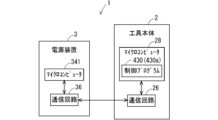
- FIG. 12 is a schematic diagram for explaining another example of a method for updating the control program 430 in the power supply device 3.
- the latest program 430a is stored in the tool body 2.
- the latest control program 430 at that time is stored in the tool body 2.
- the power supply device 3 is capable of acquiring the latest program 430a stored in the tool body 2.
- the tool body 2 includes, for example, a microcomputer 28 that stores the latest program 430a and the latest version number in association with each other.
- the microcomputer 28 may have a configuration similar to that of the microcomputer 341 of the power supply device 3.
- the voltage transmitted through the signal lines 40b and 40c of the connection cable 4 is supplied to the microcomputer 28 as a power source. Therefore, when the tool body 2 is connected to the power supply device 3, the microcomputer 28 of the connected tool body 2 starts operating.
- the microcomputer 28 of the connected tool body 2 When the tool body 2 is connected to the power supply device 3, the microcomputer 28 of the connected tool body 2 outputs the latest program 430a and the latest version number to the communication circuit 26.
- the communication circuit 26 of the connected tool body 2 transmits the input latest program 430a and the latest version number to the communication circuit 36 of the power supply device 3.
- the communication circuit 26 may communicate with the communication circuit 36 wirelessly or via wired communication.
- the communication circuit 36 when the communication circuit 36 receives the latest program 430a and the latest version number, it outputs the received latest program 430a and latest version number to the microcomputer 341.
- the CPU 400 compares the latest version number with the version number in the storage unit 410, as in the example of FIG. 11. If the latest version number is greater than the version number in the storage unit 410, the CPU 400 updates the control program 430 in the storage unit 410 with the latest program 430a. The CPU 400 then executes the updated control program 430 in the storage unit 410 to control the tool body 2. On the other hand, if the latest version number is equal to or less than the version number in the storage unit 410, the CPU 400 discards the latest program 430a and does not update the control program 430 in the storage unit 410.
- control circuit 34 updates the control program 430 in the memory unit 410 with the latest program 430a received by the communication circuit 36. This allows the power supply device 3 to appropriately respond to an increase in the number of types of tool body 2.
- the microcomputer 28 is provided separately from the communication circuit 26, but the microcomputer 26a included in the communication circuit 26 may perform the same function as the microcomputer 28.
- the microcomputer 26a may store the latest program 430a and the latest version number in association with each other.
- the server device 600 may store a plurality of control programs 440 corresponding to the latest plurality of types of tool bodies 2 to which the power supply device 3 can be connected.
- a control program 440 corresponding to the added type i.e., a control program 440 in which a control method corresponding to the added type is described
- the CPU 400 of the power supply device 3 identifies the type of connected tool body 2 as described above.
- the CPU 400 when a control program 440 (also called a corresponding control program 440) in which a control method corresponding to the identified type is described is not stored in the storage unit 410, the CPU 400 generates request information requesting transmission of the corresponding control program 440. Then, the CPU 400 outputs the request information to the communication circuit 36 through the peripheral circuit 450.
- the communication circuit 36 transmits the request information.
- the server device 600 receives the request information transmitted by the communication circuit 36.
- the server device 600 which has received the request information, transmits the corresponding control program 440 from among the multiple control programs 440 stored therein.
- the communication circuit 36 of the power supply device 3 receives the corresponding control program 440 transmitted by the server device 600.
- the corresponding control program 440 received by the communication circuit 36 is stored in the storage unit 410.
- the CPU 400 then executes the corresponding control program 440 in the storage unit 410, that is, the control program 440 in which a control method corresponding to the type of connection tool main body 2 is described.
- the tool body 2 may also store a control program 440 in which a control method according to the type of the tool body 2 is described.
- the microcomputer 28 may store the control program 440.
- the CPU 400 of the power supply device 3 identifies the type of the connected tool body 2 as described above.
- the control program 440 in which a control method according to the identified type is described, that is, the corresponding control program 440 is not stored in the storage unit 410, the CPU 400 generates request information requesting the transmission of the corresponding control program 440. Then, the CPU 400 outputs the request information to the communication circuit 36 through the peripheral circuit 450.
- the communication circuit 36 transmits the request information to the communication circuit 26 of the connected tool body 2.
- the communication circuit 26 outputs the received request information to the microcomputer 28.
- the microcomputer 28 that receives the request information outputs the control program 440 stored in itself to the communication circuit 26.
- the communication circuit 26 transmits the input control program 440 to the communication circuit 36.
- the control program 440 received by the communication circuit 36 is stored in the memory unit 410.
- the control program 440 in which a control method according to the type of tool connection body 2 is described is stored in the memory unit 410.
- the CPU 400 executes the control program 440 in which a control method according to the type of tool connection body 2 is described, which is stored in the memory unit 410.
- the control program 430 was pre-stored in the power supply device 3, but it does not have to be pre-stored in the power supply device 3.
- the power supply device 3 may acquire the latest control program 430 from the server device 600 that stores the latest control program 430, and store the acquired control program 430 in the storage unit 410.
- the power supply device 3 may also acquire the latest control program 430 from the connection tool main body 2 that stores the latest control program 430, and store the acquired control program 430 in the storage unit 410.
- the power supply device 3 can update the control program 430 in the storage unit 410 in the same manner as described above.
- the multiple control programs 440 may not be stored in advance in the power supply device 3.
- the power supply device 3 may acquire the multiple control programs 440 from a server device 600 that stores multiple control programs 440 corresponding to the latest multiple types of tool bodies 2 to which the power supply device 3 can be connected, and store the acquired multiple control programs 440 in the storage unit 410.
- the power supply device 3 may acquire the control program 440 from a connected tool body 2 that stores a control program 440 corresponding to its own type, and store the acquired control program 440 in the storage unit 410.
- the storage unit 410 of the power supply device 3 stores the multiple control programs 440 corresponding to the multiple types of tool bodies 2.
- control circuit 34 controls the connection tool body 2 based on the control program 430 or the control program 440 received by the communication circuit 36 from an external device, thereby enabling the connection tool body 2 to be appropriately controlled.
- the communication circuit 26 of the tool body 2 may transmit information other than the identification information to the microcomputer 36a (in other words, the communication circuit 36) or the microcomputer 341 (in other words, the control circuit 34) of the power supply device 3.
- the microcomputer 26a of the communication circuit 26 acquires rotation speed information of the motor 21 based on the three sensor signals 230 output by the sensor board 22.
- the communication circuit 26 then transmits the acquired rotation speed information to the microcomputer 36a or the microcomputer 341.
- an acceleration sensor is provided in the tool body 2
- the microcomputer 26a acquires information regarding an impact applied to the tool body 2 based on the output signal of the acceleration sensor.
- the communication circuit 26 then transmits the acquired information to the microcomputer 36a or the microcomputer 341.
- microcomputer 36a or microcomputer 341 may perform error detection on the received information (in other words, received data) received from communication circuit 26.
- microcomputer 36a or microcomputer 341 may function as an error detection unit that performs error detection on the received information received from communication circuit 26.
- microcomputer 26a of communication circuit 26 generates information to which an error detection code such as a parity code or a checksum is added (also called information with error detection code), and communication circuit 26 transmits the information with error detection code.
- Microcomputer 36a or microcomputer 341 performs error detection on the information with error detection code received from communication circuit 26.
- microcomputer 36a or microcomputer 341 If microcomputer 36a or microcomputer 341 detects an error in the received information (i.e., information with an error detection code) received from communication circuit 26, it may discard the received information and request retransmission from communication circuit 26.
- an error in the received information i.e., information with an error detection code
- microcomputer 36a or microcomputer 341 may perform error detection on the received information multiple times. For example, microcomputer 36a or microcomputer 341 performs error detection on the received information a predetermined number of times, which may be two or more. However, if microcomputer 36a or microcomputer 341 detects an error in the received information, it will not perform error detection thereafter even if the predetermined number of error detections have not been performed. If microcomputer 36a or microcomputer 341 completes the predetermined number of error detections without detecting an error, it determines that the received information has been properly received and uses the received information. On the other hand, if microcomputer 36a or microcomputer 341 detects an error, it discards the received information and requests retransmission from communication circuit 26.
- microcomputer 36a or microcomputer 341 may perform error detection on the received information multiple times. For example, microcomputer 36a or microcomputer 341 performs error detection on the received information a predetermined number of times, which may be two or more. However, if microcomputer 36a or microcomputer 341 detects an
- the microcomputer 36a or the microcomputer 341 When the microcomputer 36a or the microcomputer 341 receives identification information to which an error detection code has been added from the communication circuit 26 of the connection tool main body 2, the number of times error detection is performed may be changed depending on the type indicated by the identification information.
- the microcomputer 36a or microcomputer 341 performs error detection only once on the identification information with error detection code. In this case, if the microcomputer 36a or microcomputer 341 does not detect an error in the identification information with error detection code and the identification information indicates a driver drill or a polisher, it does not perform error detection a second time on the identification information with error detection code. If no error is detected in the identification information with error detection code, the control circuit 34 controls the motor 21 of the connecting tool body 2 using a control method according to the type indicated by the identification information.
- the microcomputer 36a or microcomputer 341 performs error detection on the identification information with the error detection code a predetermined number of times or more. However, if the microcomputer 36a or microcomputer 341 detects an error in the identification information with the error detection code, it does not perform error detection thereafter even if the predetermined number of error detections have not been performed. If the microcomputer 36a or microcomputer 341 completes the predetermined number of error detections without detecting an error, it determines that it has properly received the identification information. In this case, the control circuit 34 controls the motor 21 of the connecting tool body 2 using a control method according to the type indicated by the identification information. On the other hand, if the microcomputer 36a or microcomputer 341 detects an error, it discards the identification information and requests the communication circuit 26 to resend it.
- FIG. 13 is a schematic diagram showing an example of the inverter 35 provided in the tool body 2.
- the connection cable 4 is provided with six signal lines for respectively transmitting six control signals 342 for controlling the inverter 35 output from the control circuit 34, and two signal lines for respectively transmitting the positive power supply and negative power supply of the inverter 35, instead of the three signal lines 40a.
- the positive power supply of the inverter 35 is the positive potential of the DC voltage generated by the AC-DC converter 330 of the power supply unit 33
- the negative power supply of the inverter 35 is the ground potential of the DC voltage generated by the AC-DC converter 330.
- connection cable 5 of the cable-equipped power supply device 300 was detachable from the power supply device 3, but it may be fixed so as not to be detachable from the power supply device 3.
- the connection cable 4 may be fixed so as not to be detachable from the power supply device 3.
- the connection cable 4 may be fixed so as not to be detachable from the tool body 2.
- the power supply device 3 including the inverter 35 may be provided with a cooling fan to cool the inverter 35. If the tool body 2 includes the inverter 35, the inverter 35 may be cooled by the cooling fan 23 of the tool body 2.
- Fig. 14 is a schematic diagram showing an example of the configuration of a power tool 1 in which the power supply unit 3 is detachable from the tool body 2. In Fig. 14, the illustration of some of the configuration inside the housings 20 and 30 is omitted.
- the housing 30 of the power supply device 3 is detachable from the housing 20 of the tool body 2.
- a connection terminal group 370 consisting of multiple connection terminals is provided inside the housing 30.
- Each connection terminal of the connection terminal group 370 is exposed from the housing 30.
- a connection terminal group 240 consisting of multiple connection terminals is provided inside the housing 20.
- Each connection terminal of the connection terminal group 240 is exposed from the housing 20.
- the power supply device 3 includes the power supply unit 33, the control circuit 34, and the inverter 35
- the control circuit 34 is electrically connected to the sensor board 22, and the inverter 35 is electrically connected to the motor 21, as in FIG. 3 described above.
- the control circuit 34 of the power supply device 3 is electrically connected to the inverter 35 of the tool body 2 and the sensor board 22, and the DC voltage output from the AC-DC converter 330 of the power supply device 3 is supplied to the inverter 35 of the tool body 2.
- the power supply unit 33 of the power supply device 3 includes the AC-DC converter 330, but it may include a battery instead of the AC-DC converter 330. If the power supply unit 33 includes a battery, the connection cable 5 is not necessary.
- the battery may be rechargeable by a charger separate from the power tool 1.
- a charging terminal for charging the battery is provided inside the housing 30 of the power supply device 3 so as to be exposed from the housing 30. The charging voltage from the charger is then supplied to the charging terminal to charge the battery.
- the DC voltage output from the battery is supplied to the inverter 35 and the DC-DC converter 340 of the control circuit 34 instead of the DC voltage generated by the AC-DC converter 330.
- the power supply device 3 can be connected to multiple types of tool body 2, but the power supply device 3 may be connected to only one type of tool body 2.
- the storage unit 410 of the power supply device 3 may store a control program 440 that describes a control method corresponding to one type of tool body 2 to which the power supply device 3 can be connected.
- This disclosure includes the following:
- the power supply device is a power supply device that can be connected to each of multiple types of electric power tool bodies, and includes a control circuit that controls a connection tool body, which is an electric power tool body connected to the power supply device, and a power supply unit that supplies power to the connection tool body and the control circuit, the control circuit stores multiple types of control methods corresponding to the multiple types of electric power tool bodies, the control circuit identifies the type of the connection tool body, and controls the connection tool body using a control method corresponding to the identified type from the multiple types of control methods.
- the control circuit acquires identification information indicating the type of the connection tool body and identifies the type of the connection tool body.
- the power supply device of (2) above is equipped with a communication circuit that receives the identification information transmitted by the connection tool body.
- the communication circuit is a wireless communication circuit.
- the identification information indicates the value of the resistive voltage divider generated by the resistive voltage divider circuit.
- the resistive voltage divider circuit has a first resistive element and a second resistive element, the first resistive element is provided in the power supply device, and the second resistive element is provided in the connecting tool body.
- the connection tool body transmits the identification information to which an error detection code has been added, and includes an error detection unit that performs error detection on the identification information to which the error detection code has been added, and the error detection unit changes the number of times the error detection is performed depending on the type indicated by the identification information.
- control circuit controls the connection tool body based on a control program that describes a control method according to the type of the connection tool body.
- control program describes the multiple types of control methods, and the control circuit is capable of controlling each of the multiple types of power tool bodies based on the control program.
- the power supply device of (8) or (9) above is equipped with a communication circuit that receives the control program stored in a device external to the power supply device.
- the power supply device is a power supply device connected to an electric power tool body, and includes a communication circuit that receives a first control program stored in a device external to the power supply device, a control circuit that controls the electric power tool body based on the first control program received by the communication circuit, and a power supply unit that outputs power to the electric power tool body and the control circuit.
- the communication circuit is a wireless communication circuit.
- the power tool body functions as the external device that stores the first control program.
- control circuit updates the second control program stored in the power supply device for controlling each of the multiple types of power tool bodies with the first control program received by the communication circuit.
- the electric power tool includes any one of the power supply devices (1) to (16) above and an electric power tool body to which the power supply device is connected.
- Power tool 2 Power tool body 2A Connection tool body 3 Power supply device 27 Resistance voltage divider circuit 33 Power supply unit 34 Control circuit 341 Microcomputer 36 Communication circuit 400 CPU 430, 440 Control program 450 Peripheral circuit 600 Server device 700 Portable electronic device R1, R2 Resistance element
Landscapes
- Engineering & Computer Science (AREA)
- Mechanical Engineering (AREA)
- Portable Power Tools In General (AREA)
Priority Applications (1)
| Application Number | Priority Date | Filing Date | Title |
|---|---|---|---|
| JP2025506604A JPWO2024190243A1 (https=) | 2023-03-15 | 2024-02-14 |
Applications Claiming Priority (2)
| Application Number | Priority Date | Filing Date | Title |
|---|---|---|---|
| JP2023-041130 | 2023-03-15 | ||
| JP2023041130 | 2023-03-15 |
Publications (1)
| Publication Number | Publication Date |
|---|---|
| WO2024190243A1 true WO2024190243A1 (ja) | 2024-09-19 |
Family
ID=92755347
Family Applications (1)
| Application Number | Title | Priority Date | Filing Date |
|---|---|---|---|
| PCT/JP2024/004977 Ceased WO2024190243A1 (ja) | 2023-03-15 | 2024-02-14 | 電源装置及び電動工具 |
Country Status (2)
| Country | Link |
|---|---|
| JP (1) | JPWO2024190243A1 (https=) |
| WO (1) | WO2024190243A1 (https=) |
Citations (6)
| Publication number | Priority date | Publication date | Assignee | Title |
|---|---|---|---|---|
| JPS6451277A (en) * | 1987-08-07 | 1989-02-27 | Festo Kg | Power supply unit capable of being connected to various power tool |
| JP2006205286A (ja) * | 2005-01-26 | 2006-08-10 | Matsushita Electric Works Ltd | 手持ち式電動工具 |
| JP2013000863A (ja) * | 2011-06-20 | 2013-01-07 | Hitachi Koki Co Ltd | 電動工具 |
| JP2020023008A (ja) * | 2018-08-06 | 2020-02-13 | パナソニックIpマネジメント株式会社 | 電動工具 |
| WO2021054302A1 (ja) * | 2019-09-17 | 2021-03-25 | 京セラインダストリアルツールズ株式会社 | 電源装置、ケーブル付き電源装置及び電動工具 |
| JP2022058575A (ja) * | 2011-07-24 | 2022-04-12 | 株式会社マキタ | 動力工具システムとそのバッテリパック |
-
2024
- 2024-02-14 JP JP2025506604A patent/JPWO2024190243A1/ja active Pending
- 2024-02-14 WO PCT/JP2024/004977 patent/WO2024190243A1/ja not_active Ceased
Patent Citations (6)
| Publication number | Priority date | Publication date | Assignee | Title |
|---|---|---|---|---|
| JPS6451277A (en) * | 1987-08-07 | 1989-02-27 | Festo Kg | Power supply unit capable of being connected to various power tool |
| JP2006205286A (ja) * | 2005-01-26 | 2006-08-10 | Matsushita Electric Works Ltd | 手持ち式電動工具 |
| JP2013000863A (ja) * | 2011-06-20 | 2013-01-07 | Hitachi Koki Co Ltd | 電動工具 |
| JP2022058575A (ja) * | 2011-07-24 | 2022-04-12 | 株式会社マキタ | 動力工具システムとそのバッテリパック |
| JP2020023008A (ja) * | 2018-08-06 | 2020-02-13 | パナソニックIpマネジメント株式会社 | 電動工具 |
| WO2021054302A1 (ja) * | 2019-09-17 | 2021-03-25 | 京セラインダストリアルツールズ株式会社 | 電源装置、ケーブル付き電源装置及び電動工具 |
Also Published As
| Publication number | Publication date |
|---|---|
| JPWO2024190243A1 (https=) | 2024-09-19 |
Similar Documents
| Publication | Publication Date | Title |
|---|---|---|
| EP3404826B1 (en) | Method and device for controlling rotation angle of swinging head of fan, and fan | |
| CN103886247B (zh) | 具有中央授权管理单元和工具装置的系统 | |
| JP6399437B2 (ja) | 制御装置及びそれを用いた作業管理システム | |
| US9794347B2 (en) | Systems and methods for selecting and wirelessly programming a motor | |
| EP4597795A2 (en) | Electronic device and method for controlling recharge of battery | |
| US20150316913A1 (en) | An interface for a power tool | |
| JP2016135099A (ja) | 無線充電装置をヒューマンマシンインターフェース(hmi)と一体化させる方法 | |
| CN108883527B (zh) | 具有设定数据发送功能的电动工具的控制电路、电动工具、控制装置以及电动工具系统 | |
| US9857846B2 (en) | Portable computing device cover including a keyboard | |
| JP6544700B2 (ja) | 制御装置及びそれを用いた作業管理システム | |
| JP2019188599A (ja) | 制御装置及びそれを用いた作業管理システム | |
| CN107933935B (zh) | 无人机控制系统 | |
| JP7602581B2 (ja) | 電動工具 | |
| CN116262453A (zh) | 用于对包含电池的电动车辆进行充电的系统及方法 | |
| WO2024190243A1 (ja) | 電源装置及び電動工具 | |
| TW201817553A (zh) | 電動工具及其操控方法 | |
| CN116262452A (zh) | 用于对包含电池的电动车辆进行充电的系统及方法 | |
| US20250348057A1 (en) | Electric tool system, control method, and program | |
| EP4434678A1 (en) | Electric tool system, electric tool management method, and program | |
| CN110553857B (zh) | 一种电动助力转向测试系统和方法 | |
| WO2024195571A1 (ja) | 電源装置、電動工具本体及び電動工具 | |
| CN108161955A (zh) | 机器人控制装置 | |
| JP2019103180A (ja) | モータ駆動制御装置、モータ駆動システム、モータ駆動制御装置の制御方法、及びモータ駆動制御装置の制御プログラム。 | |
| CN222674545U (zh) | 舞台灯光控台 | |
| JP7535756B2 (ja) | 制御装置 |
Legal Events
| Date | Code | Title | Description |
|---|---|---|---|
| 121 | Ep: the epo has been informed by wipo that ep was designated in this application |
Ref document number: 24770358 Country of ref document: EP Kind code of ref document: A1 |
|
| ENP | Entry into the national phase |
Ref document number: 2025506604 Country of ref document: JP Kind code of ref document: A |
|
| WWE | Wipo information: entry into national phase |
Ref document number: 2025506604 Country of ref document: JP |
|
| NENP | Non-entry into the national phase |
Ref country code: DE |
|
| 122 | Ep: pct application non-entry in european phase |
Ref document number: 24770358 Country of ref document: EP Kind code of ref document: A1 |