WO2024190121A1 - 空中像表示装置 - Google Patents
空中像表示装置 Download PDFInfo
- Publication number
- WO2024190121A1 WO2024190121A1 PCT/JP2024/002883 JP2024002883W WO2024190121A1 WO 2024190121 A1 WO2024190121 A1 WO 2024190121A1 JP 2024002883 W JP2024002883 W JP 2024002883W WO 2024190121 A1 WO2024190121 A1 WO 2024190121A1
- Authority
- WO
- WIPO (PCT)
- Prior art keywords
- light
- image display
- guide plate
- optical system
- light guide
- Prior art date
- Legal status (The legal status is an assumption and is not a legal conclusion. Google has not performed a legal analysis and makes no representation as to the accuracy of the status listed.)
- Ceased
Links
Images



Classifications
-
- G—PHYSICS
- G02—OPTICS
- G02B—OPTICAL ELEMENTS, SYSTEMS OR APPARATUS
- G02B30/00—Optical systems or apparatus for producing three-dimensional [3D] effects, e.g. stereoscopic images
- G02B30/50—Optical systems or apparatus for producing three-dimensional [3D] effects, e.g. stereoscopic images the image being built up from image elements distributed over a three-dimensional [3D] volume, e.g. voxels
- G02B30/56—Optical systems or apparatus for producing three-dimensional [3D] effects, e.g. stereoscopic images the image being built up from image elements distributed over a three-dimensional [3D] volume, e.g. voxels by projecting aerial or floating images
-
- H—ELECTRICITY
- H04—ELECTRIC COMMUNICATION TECHNIQUE
- H04N—PICTORIAL COMMUNICATION, e.g. TELEVISION
- H04N13/00—Stereoscopic video systems; Multi-view video systems; Details thereof
- H04N13/30—Image reproducers
- H04N13/302—Image reproducers for viewing without the aid of special glasses, i.e. using autostereoscopic displays
Definitions
- the present invention relates to an aerial image display device.
- Patent Document 1 describes an aerial image projection device that includes a first reflecting element configured to transmit a portion of a first image light that is incident from a first direction and indicates an image in a second direction and to reflect a portion of a second image light that is incident from the second direction in a third direction, a second reflecting element configured to retro-reflect the first image light that has transmitted through the first reflecting element as a second image light, and a first optical element positioned between the first reflecting element and the second reflecting element and configured to collect the first image light and collect the second image light.
- the objective of the present invention is to provide a new aerial image display device that is different from any of the above.
- the present invention has the following configuration.
- An image display element a light guide plate that guides light emitted from the image display element; a light collecting optical system that collects the light guided through the light guide plate, A reflecting section is provided to reflect the light guided through the light guide plate and cause the light to enter the light collecting optical system.
- the aerial image display device according to any one of [1] to [3], wherein the focusing optical system includes a liquid crystal lens.
- the aerial image display device according to any one of [1] to [4], further comprising an incident diffraction element that causes light emitted from the image display element to enter a light guide plate.
- the aerial image display device according to any one of [1] to [5], further comprising an exit diffraction element that causes light guided within a light guide plate to exit the light guide plate.
- the present invention provides a novel aerial image display device.
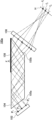
- FIG. 1 is a diagram conceptually illustrating an example of an aerial image display device of the present invention.
- FIG. 13 is a diagram conceptually illustrating another example of the aerial image display device of the present invention.
- FIG. 13 is a diagram conceptually illustrating another example of the aerial image display device of the present invention.
- FIG. 13 is a diagram conceptually illustrating another example of the aerial image display device of the present invention.
- FIG. 13 is a diagram conceptually illustrating another example of the aerial image display device of the present invention.
- FIG. 13 is a diagram conceptually illustrating another example of the aerial image display device of the present invention.
- FIG. 1 is a diagram conceptually illustrating an example of a conventional aerial image display device.
- the difference from the exact angle is preferably less than 3 degrees, and more preferably less than 1 degree.
- terms such as “same” and “equal” include a generally accepted margin of error in the relevant technical field.
- Visible light is electromagnetic radiation having a wavelength that can be seen by the human eye, and refers to light having a wavelength in the range of 380 to 780 nm.
- the aerial image display device of the present invention comprises: An image display element; a light guide plate that guides light emitted from the image display element; a light collecting optical system that collects the light guided through the light guide plate, A reflecting section is provided to reflect the light guided through the light guide plate and cause the light to enter the light collecting optical system.
- This is an aerial image display device in which the reflecting portion is closer to the focusing optical system than the focal length of the focusing optical system.
- the light guide plate 104 is a known light guide plate that guides light inside.
- the light guide plate is a substantially plate-shaped member.
- the light guide plate 104 has a substantially trapezoidal shape when viewed in a cross section in the light guide direction. That is, in the example shown in FIG. 1, the light guide plate 104 has two side surfaces (surfaces arranged on the left and right in the figure) that are inclined with respect to the main surface (surfaces arranged on the top and bottom in the figure).
- the light guide plate 104 receives light from one side surface (the side surface on the left in the figure), and the light that has entered the light guide plate 104 is totally reflected by the two main surfaces (interfaces with the air layer), guides the light from the left to the right in the figure, and emits the light from the other side surface (the side surface on the right in the figure).
- the main surface refers to the largest surface of a plate-like member (sheet-like member).
- incident surface 105a The side where light is incident (incident surface 105a) is inclined with respect to the main surface so that light incident from a direction approximately perpendicular to incident surface 105a is at an angle where it is totally reflected by the main surface (an angle that satisfies the total reflection condition).
- exit surface 105b the side where light is emitted (exit surface 105b) is inclined with respect to the main surface so that the light guided inside light guide plate 104 is at an angle where it is emitted without being totally reflected by exit surface 105b.
- the inclination angle of the incident surface 105a with respect to the main surface can be set appropriately depending on the refractive index of the light guide plate 104, etc., and is preferably 40° to 70°, more preferably 42° to 65°, and even more preferably 45° to 60°.
- the thickness of light guide plate 104 is preferably 0.01 mm to 500 mm, more preferably 0.05 mm to 100 mm, and even more preferably 0.1 mm to 10 mm.
- the size of the main surface of the light guide plate 104 may be set appropriately depending on the size of the aerial image displayed by the aerial image display device, the size of the display surface of the image display element 102, etc.
- an image display element 102 is disposed facing the side surface that serves as the incident surface 105a of the light guide plate 104.
- the image display element 102 irradiates image light (still image or video) that serves as an aerial image toward the incident surface 105a of the light guide plate 104.
- image light still image or video
- the display surface of the image display element 102 may be disposed parallel or non-parallel to the incident surface 105a of the light guide plate 104.
- image display element There are no limitations on the image display element, and for example, various known displays used in image display devices, etc. can be used.
- image display elements include liquid crystal display elements (LCDs (Liquid Crystal Display)), organic electroluminescent display elements (OLEDs (Organic Light Emitting Diodes)), CRTs (cathode-ray tubes), plasma display elements, electronic paper, LED (Light Emitting Diode) display elements, micro LED display elements, DLPs (Digital Light Processing), and MEMS (Micro-Electro-Mechanical Systems) display elements.
- LCDs Liquid Crystal Display
- OLEDs Organic Light Emitting Diodes
- CRTs cathode-ray tubes
- plasma display elements electronic paper
- LED (Light Emitting Diode) display elements micro LED display elements
- DLPs Digital Light Processing
- MEMS Micro-Electro-Mechanical Systems
- liquid crystal display elements include LCOS (Liquid Crystal On Silicon), etc.
- the image display element may be one that displays monochrome images, two-tone images, or color images.
- the light emitted by the image display element may be unpolarized, linearly polarized, or circularly polarized.
- the aerial image display device may also have an optical component that converts the polarization state of the light emitted by the image display element.
- the focusing optical system 106 is disposed facing the side of the light guide plate 104 that serves as the exit surface 105b.
- the focusing optical system 106 includes one or more lenses and has the function of focusing the incident light.
- the focusing optical system 106 is disposed facing the side surface that becomes the exit surface 105b of the light guide plate 104, and focuses the light that is emitted from the light guide plate 104. In this way, the image irradiated by the image display element 102 is focused in the air and displayed as an aerial image.
- the image display element 102 emits planar light (image). At that time, as shown in FIG. 1, the light emitted from each point (each pixel) on the display surface of the image display element 102 is emitted as diffused light. The light emitted from a certain point on the image display element 102 is guided inside the light guide plate 104 while spreading, and is emitted from the exit surface 105b and enters the focusing optical system 106. The diffused light that enters the focusing optical system 106 is focused and forms an image at a point in the air.
- each point (each pixel) on the display surface of the image display element 102 forms an image at a different point in the air.
- diffuse light emitted from point P1 of the image display element 102 forms an image at point f1 in the air
- diffuse light emitted from point P2 of the image display element 102 forms an image at point f2 in the air
- diffuse light emitted from point P3 of the image display element 102 forms an image at point f3 in the air.
- each point (each pixel) on the display surface of the image display element 102 forms an image at a different point in the air, and thus the image irradiated by the image display element 102 is displayed as an aerial image H, as shown by the thick dashed line in the figure.
- the reflecting section that reflects the light guided through the light guide plate and makes it enter the focusing optical system is closer to the focusing optical system than the focal point of the focusing optical system. This point will be explained using Figure 1.
- a reflecting portion is a portion on the light path that reflects light immediately before (directly upstream) the focusing optical system.
- the light irradiated by the image display element 102 and guided through the light guide plate 104 is reflected multiple times by the main surface (interface) of the light guide plate 104, and then emitted from the exit surface of the light guide plate 104 to enter the focusing optical system 106. Therefore, as shown in FIG. 1, a partial area of the main surface of the light guide plate 104 that reflects the light immediately before it enters the focusing optical system 106 corresponds to the reflecting portion 108.
- Such a reflecting portion 108 is closer to the focusing optical system 106 than the focal point F of the focusing optical system 106. More specifically, as shown in FIG. 1, on the optical axis of the focusing optical system 106, the reflecting portion 108 is disposed at a position closer to the focusing optical system 106 than the focal point F of the focusing optical system.
- the aerial image display device 200 shown in FIG. 7 if the reflector 208 is located farther from the focusing optical system 206 than the focal point F of the focusing optical system 206, the aerial image H will be displayed at a position closer to the focusing optical system 206. This will result in an image that lacks a sense of floating.
- the reflector 108 is closer to the focusing optical system 106 than the focal point F of the focusing optical system 106. Therefore, the aerial image H is displayed at a position farther away from the focusing optical system 106. This makes it possible to display an image that gives the impression of floating.
- the aerial image display device 100a of the present invention does not use a half mirror, it can efficiently use the light emitted by the image display element 102, thereby increasing the brightness of the displayed aerial image H.
- the aerial image display device 100a of the present invention uses a light guide plate 104 to guide light from the image display element 102 to the focusing optical system 106, making it possible to make the device thinner.
- the focal length of the focusing optical system in order to position the reflecting section 108 closer to the focusing optical system 106 than the focal point F of the focusing optical system 106, the focal length of the focusing optical system, the distance between the focusing optical system 106 and the exit surface 105b of the light guide plate 104, and the thickness of the light guide plate 104, etc., can be set appropriately.
- the focusing optical system 106 has one lens, but this is not limited to this and may have multiple lenses. In other words, the focusing optical system may be a lens combination.
- the focusing optical system 106 may have three lenses 106a to 106c.
- the focusing optical system 106 By configuring the focusing optical system 106 with multiple lenses, aberration can be suppressed and the resolution of the aerial image H can be increased.
- the focusing optical system when the focusing optical system is constructed from multiple lenses, there is no limit to the number of lenses used. However, if the focusing optical system has a large number of lenses, a distance between the lenses is required equal to the number of lenses. Therefore, taking into consideration the size of the aerial image display device, it is preferable to use three or fewer lenses. In other words, in the present invention, it is preferable that the focusing optical system has one to three lenses.
- the focusing optical system 106 is made up of one lens, a convex lens (focusing lens), a Fresnel lens, or the like can be used as the lens. If the focusing optical system 106 is made up of multiple lenses, the lenses may be the same lens, or different lenses may be combined. If the focusing optical system 106 has multiple lenses, the lenses may be an optical system that combines multiple lenses and has a focusing effect, and the lenses that can be used may be convex lenses, concave lenses, meniscus lenses, or the like.
- the lens is not limited to a general lens made of glass, transparent plastic, etc., formed into a convex or concave shape, but may be a liquid crystal lens.
- a liquid crystal lens is a lens that diffracts incident light in each region in the plane by orienting liquid crystal compounds in a specific orientation pattern, and exhibits the function of converging or diverging the light.
- a liquid crystal lens is an optical element (liquid crystal diffraction element) that has a liquid crystal layer (optically anisotropic layer) having a liquid crystal orientation pattern in which the direction of the optical axis derived from the liquid crystal compound changes while continuously rotating along at least one direction in the plane, and this one direction is concentrically arranged from the inside to the outside.
- Such a liquid crystal lens mainly diffracts circularly polarized light, and acts as a converging lens or a diverging lens depending on the rotation direction of the incident circularly polarized light.
- a liquid crystal lens acts as a converging lens when right-handed circularly polarized light is incident, and acts as a diverging lens when left-handed circularly polarized light is incident.
- the liquid crystal lens acts as a condensing lens when left-handed circularly polarized light is incident, and acts as a diverging lens when right-handed circularly polarized light is incident.
- Liquid crystal lenses are described in paragraphs [0076] to [0084] of International Publication No. 2020/022513, International Publication No. 2022/050321, etc.
- liquid crystal lenses mainly diffract circularly polarized light. Therefore, when the focusing optical system 106 includes a liquid crystal lens, it is preferable to provide an optical element that converts the light incident on the focusing optical system 106 into circularly polarized light in the rotation direction that the liquid crystal lens collects. Specifically, when the image display element 106 emits unpolarized light, it is preferable to provide a polarizing plate and a ⁇ /4 plate (1/4 wavelength plate) between the image display element 102 and the focusing optical system 106 to convert the light incident on the focusing optical system 106 into circularly polarized light in the rotation direction that the liquid crystal lens collects.
- the image display element 102 when the image display element 102 emits linearly polarized light like a liquid crystal display device, it is preferable to provide a ⁇ /4 plate between the image display element 102 and the focusing optical system 106 to convert the light incident on the focusing optical system 106 into circularly polarized light in the rotation direction that the liquid crystal lens collects.
- the polarizing plate may be either a reflective polarizing plate or an absorptive polarizing plate, and various known linear polarizing plates can be used, such as iodine-based polarizing plates, dye-based polarizing plates using dichroic dyes, polyene-based polarizing plates, wire grid polarizing plates, and films made of stretched dielectric multilayer films as described in JP 2011-053705 A, etc.
- ⁇ /4 plate there are also no limitations on the ⁇ /4 plate. Therefore, various known ⁇ /4 plates can be used, such as stretched polycarbonate films, stretched norbornene-based polymer films, transparent films containing and oriented with inorganic particles having birefringence such as strontium carbonate, thin films formed by obliquely depositing inorganic dielectrics onto a support, films in which polymerizable liquid crystal compounds are uniaxially oriented and oriented, and films in which liquid crystal compounds are uniaxially oriented and oriented.
- stretched polycarbonate films stretched norbornene-based polymer films
- transparent films containing and oriented with inorganic particles having birefringence such as strontium carbonate
- thin films formed by obliquely depositing inorganic dielectrics onto a support films in which polymerizable liquid crystal compounds are uniaxially oriented and oriented, and films in which liquid crystal compounds are uniaxially oriented and oriented.
- the focusing position of the light (display image) by the focusing optical system 106 i.e., the focal length (lens power) of the focusing optical system 106, is not limited as long as the reflecting unit 108 is closer to the focusing optical system 106 than the focal point of the focusing optical system 106.
- the focusing position of the light by the focusing optical system 106 may be set appropriately depending on the position where the aerial image is displayed, the magnification ratio and reduction ratio of the aerial image, etc.
- the focusing optical system may also be capable of changing the focal length. By making the focal length of the focusing optical system variable, the position at which the aerial image is displayed can be changed.
- a focusing optical system with a variable focal length may be configured such that at least some of the lenses that make up the focusing optical system are movable, or may include a variable focus lens.
- An example of a variable focus lens is a lens formed using a medium whose optical properties, such as refractive index, change when a voltage is applied. The focal length of this lens can be changed by applying a voltage to change the refractive index distribution within the medium.
- the incident surface through which light from the image display element 102 enters the light guide plate 104 is inclined relative to the main surface, but the present invention is not limited to this, and the aerial image display device of the present invention may have an incident diffraction element for causing light emitted by the image display element to enter the light guide plate.
- the exit surface through which light guided within the light guide plate 104 exits is inclined relative to the main surface, but the present invention is not limited to this, and the aerial image display device of the present invention may have an exit diffraction element for causing light guided within the light guide plate to exit from the light guide plate.
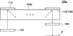
- FIG. 3 is a diagram conceptually showing another example of the aerial image display device of the present invention.
- the aerial image display device 100c shown in Fig. 3 includes an image display element 102, a light guide plate 104b, a reflective input diffraction element 112, a reflective output diffraction element 110, and a light collecting optical system 106.
- the same components as those in the aerial image display device 100a shown in Fig. 1 are denoted by the same reference numerals, and the following description will mainly focus on the different components. This also applies to Fig. 4 and subsequent figures described later.
- Light guide plate 104b is a known light guide plate that guides light inside.
- the light guide plate is a roughly plate-shaped member, with the side surfaces roughly perpendicular to the main surface.
- a reflective incident diffraction element 112 is disposed at one end of one of the principal surfaces of the light guide plate 104b in the light guide direction (left-right direction in the figure).
- the image display element 102 faces the principal surface opposite the principal surface on which the incident diffraction element 112 of the light guide plate 104b is disposed, and is disposed at a position corresponding to the incident diffraction element 112, i.e., at a position overlapping with the principal surface in the in-plane direction.
- the incident diffraction element 112 reflects and diffracts the light that is emitted from the image display element 102 and incident on the main surface of the light guide plate 104b in a direction approximately perpendicular to the main surface of the light guide plate 104b, at an angle that satisfies the total reflection condition.
- the light reflected and diffracted by the incident diffraction element 112 is guided through the light guide plate 104b while being totally reflected by both main surfaces of the light guide plate 104b (the interfaces with the air layer).
- a reflective output diffraction element 110 is disposed at the other end of one of the main surfaces of the light guide plate 104b in the light guide direction (left and right direction in the figure).
- the light collecting optical system 106 faces the main surface of the light guide plate 104b opposite the main surface on which the output diffraction element 110 is disposed, and is disposed at a position corresponding to the output diffraction element 110, i.e., at a position overlapping the in-plane direction of the main surface.
- the output diffraction element 110 reflects and diffracts the light guided through the light guide plate 104b at an angle that deviates from the total reflection condition.
- the output diffraction element 110 reflects and diffracts the light in a direction approximately perpendicular to the main surface.
- the light reflected and diffracted by the output diffraction element 110 is emitted from the light guide plate 104b and enters the focusing optical system 106.
- the focusing optical system 106 focuses the incident light and forms an image in the air that is irradiated by the image display element 102, and displays it as an aerial image H.
- the reflecting section that reflects the light guided through the light guide plate and causes it to enter the focusing optical system is closer to the focusing optical system than the focal point of the focusing optical system.
- the output diffraction element 110 corresponds to the reflecting section 108. Therefore, on the optical axis of the focusing optical system 106, the output diffraction element 110 is positioned closer to the focusing optical system 106 than the focal point of the focusing optical system 106.
- the aerial image H is displayed at a position farther away from the focusing optical system 106, making it possible to display an image with a floating feel. Furthermore, because the aerial image display device 100c does not use a half mirror, it is possible to efficiently utilize the light irradiated by the image display element 102, and to increase the brightness of the displayed aerial image H. Furthermore, because the aerial image display device 100c uses the light guide plate 104b to guide light from the image display element 102 to the focusing optical system 106, the device can be made thinner.
- the attachment layer can be a layer made of various known materials as long as it is a layer that can attach the objects to be attached to each other.
- the attachment layer may be a layer made of an adhesive that has fluidity when attached and then becomes solid, a layer made of a pressure-sensitive adhesive that is a soft solid in a gel (rubber-like) state when attached and does not change to a gel state thereafter, or a layer made of a material that has the characteristics of both an adhesive and a pressure-sensitive adhesive. Therefore, the attachment layer may be a known layer used for attaching sheet-like objects in optical devices and optical elements, such as an optically clear adhesive (OCA (Optical Clear Adhesive)), an optically clear double-sided tape, and an ultraviolet-curing resin.
- OCA optical Clear Adhesive
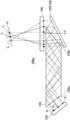
- FIG. 4 is a diagram conceptually showing another example of the aerial image display device of the present invention.
- the aerial image display device 100d shown in FIG. 4 has an image display element 102, a light guide plate 104b, a transmissive input diffraction element 116, a transmissive output diffraction element 114, and a focusing optical system 106.
- the incident diffraction element 116 transmits and diffracts the light that is emitted from the image display element 102 and enters the main surface of the light guide plate 104b in a direction approximately perpendicular to the main surface of the light guide plate 104b, at an angle that satisfies the total reflection condition.
- the light transmitted and diffracted by the incident diffraction element 112 is guided through the light guide plate 104b while being totally reflected by both main surfaces (interfaces) of the light guide plate 104b.
- a transmissive output diffraction element 114 is disposed at the other end of one of the main surfaces of the light guide plate 104b in the light guide direction (left and right direction in the figure).
- the light collecting optical system 106 is disposed at a position facing the output diffraction element 114 on the main surface side where the output diffraction element 114 of the light guide plate 104b is disposed, that is, at a position overlapping in the in-plane direction of the main surface.
- the output diffraction element 114 transmits and diffracts the light guided through the light guide plate 104b at an angle that deviates from the total reflection condition.
- the output diffraction element 114 reflects and diffracts the light in a direction approximately perpendicular to the main surface.
- the reflecting section that reflects the light guided through the light guide plate and makes it enter the focusing optical system is closer to the focusing optical system than the focal point of the focusing optical system.
- a partial area of the main surface of the light guide plate 104b that reflects the light on the optical path before the light enters the focusing optical system 106 and immediately before it enters the output diffraction element 114 corresponds to the reflecting section 108.
- the surface of the light guide plate 104b opposite the surface on which the output diffraction element 114 is located is located closer to the focusing optical system 106 than the focal point of the focusing optical system 106.
- the aerial image H is displayed at a position farther away from the focusing optical system 106, making it possible to display an image with a floating feel. Furthermore, because the aerial image display device 100d does not use a half mirror, it is possible to efficiently utilize the light irradiated by the image display element 102, and to increase the brightness of the displayed aerial image H. Furthermore, because the aerial image display device 100d uses the light guide plate 104b to guide light from the image display element 102 to the focusing optical system 106, the device can be made thinner.
- the incident diffraction element and the exit diffraction element are arranged on the same main surface of the light guide plate 104b, but this is not limited to the above.
- the incident diffraction element and the exit diffraction element may be arranged on different main surfaces of the light guide plate 104b.
- the image display element 102 and the focusing optical system 106 are arranged on different main surfaces of the light guide plate 104b.
- the incident side may have an incident surface inclined with respect to the main surface as shown in FIG. 1, and the exit side may have an exit diffraction element as shown in FIG. 3 or FIG. 4, or the incident side may have an incident diffraction element as shown in FIG. 3 or FIG. 4, and the exit side may have an exit diffraction element inclined with respect to the main surface as shown in FIG. 1.
- the incident diffraction element and the image display element 102 there may be another layer between the incident diffraction element and the image display element 102.
- the incident diffraction element and the exit diffraction element have circular polarization selectivity
- the image display element 102 irradiates linearly polarized light, or if the image display element 102 has a linear polarizing plate on the display surface side, a configuration having a ⁇ /4 plate between the incident diffraction element and the light guide plate may be used.
- the linearly polarized light irradiated from the image display element 102 (or converted by the linear polarizing plate) is converted to circularly polarized light by the ⁇ /4 plate and enters the incident diffraction element.
- the ⁇ /4 plate is positioned so as to convert the linearly polarized light irradiated from the image display element 102 into circularly polarized light in the rotation direction reflected by the incident diffraction element.
- the input diffraction element and output diffraction element are not limited to being configured with circular polarization selectivity, and the light guided through the light guide plate may be linearly polarized, and the input diffraction element and output diffraction element may be configured with linear polarization selectivity.
- diffraction element As the incident diffraction element and the exit diffraction element, a conventionally known diffraction element can be appropriately used. In the following description, when it is not necessary to distinguish between a reflection type incident diffraction element, a transmission type incident diffraction element, a reflection type exit diffraction element, and a transmission type exit diffraction element, they are collectively referred to as diffraction elements. When it is not necessary to distinguish between a reflection type incident diffraction element and a reflection type exit diffraction element, they are collectively referred to as reflection type diffraction elements. When it is not necessary to distinguish between a transmission type incident diffraction element and a transmission type exit diffraction element, they are collectively referred to as transmission type diffraction elements.
- These diffraction elements are preferably any one of a surface relief type diffraction element, a volume hologram type diffraction element, and a polarizing diffraction element.
- the polarizing diffraction element is preferably a liquid crystal diffraction element formed by using a composition containing a liquid crystal compound.
- the reflective liquid crystal diffraction element preferably has a cholesteric liquid crystal layer formed by fixing a cholesteric liquid crystal phase. The configuration of each diffraction element will be described below.
- a known surface relief type diffraction element can be used as the surface relief type diffraction element.
- a surface relief type diffraction element is configured with linear fine projections and recesses arranged alternately in parallel at a predetermined period on the surface. The period, material, and height of the projections of the diffraction structure can be appropriately set according to the wavelength range to be diffracted.
- the surface relief type diffraction element may be one in which a diffraction structure (uneven structure) is formed on the surface of a film-like material made of resin or the like, or one in which a diffraction structure (uneven structure) is formed directly on the surface of a light guide plate.
- volume hologram type diffraction element A known volume hologram type diffraction element can be used as the volume hologram type diffraction element.
- a volume hologram type diffraction element is configured by alternating linear regions with high refractive index and linear regions with low refractive index arranged in parallel at a predetermined period. The period of the diffraction structure, the material, and the refractive index of each region can be appropriately set depending on the wavelength range to be diffracted.
- the polarizing diffraction element is a diffraction element that controls the diffraction direction, polarization state, and diffracted light intensity of the emitted light according to the polarization state of the incident light by controlling the polarization state in a fine region.
- polarizing diffraction element examples include a polarizing diffraction element in which a diffraction structure is formed using structural birefringence described in "Erez Hasman et al., Polarization dependent focusing lens by use of quantized Pancharatnm-Berry phase diffractive optics, Applied Physics Letters, Volume 82, Number 3 pp.328-330" and a polarizing diffraction element in which a diffraction structure is formed using a birefringent material described in Japanese Patent No. 5276847.
- a polarizing diffraction element is a liquid crystal diffraction element that is formed using a composition containing a liquid crystal compound and has a liquid crystal layer having a liquid crystal orientation pattern in which the direction of the optical axis derived from the liquid crystal compound changes while continuously rotating along at least one direction in the plane.
- the reflective liquid crystal diffraction element examples include an optical element including a cholesteric liquid crystal layer having a liquid crystal orientation pattern in which a cholesteric liquid crystal phase is fixed and the direction of the optical axis derived from the liquid crystal compound changes while continuously rotating along at least one direction in the plane.
- Such a reflective liquid crystal diffraction element is described in WO 2020/226078, WO 2020/122128, etc.
- each diffraction element may have one cholesteric liquid crystal layer having wavelength selectivity, or may have two or more layers.
- the diffraction element has two or more cholesteric liquid crystal layers
- the diffraction element may have two cholesteric liquid crystal layers, one that selectively reflects red light and the other that selectively reflects green light, or it may have three liquid crystal layers, one that selectively reflects red light, one that selectively reflects green light, and another that selectively reflects blue light.
- each cholesteric liquid crystal layer can be configured to reflect three colors of light, namely red light, green light, and blue light, thereby enabling the aerial image display device to display a color image.
- the diffraction element may have three cholesteric liquid crystal layers with different selective reflection center wavelengths, and may be configured to reflect one or two colors selected from visible light such as red light, green light, and blue light, as well as infrared light and/or ultraviolet light, or may be configured to reflect only light other than visible light.
- the diffraction element may have two or four or more cholesteric liquid crystal layers having different selective reflection central wavelengths.
- the diffraction element may be configured to reflect light other than visible light, such as infrared light and/or ultraviolet light, in addition to visible light, such as red light, green light, and blue light, or each cholesteric liquid crystal layer may be configured to reflect light other than visible light, such as infrared light and/or ultraviolet light.
- the transmission type liquid crystal diffraction element is a liquid crystal diffraction element having a liquid crystal orientation pattern that is continuously rotated along at least one direction in the plane, and in which the liquid crystal compound does not form a cholesteric liquid crystal phase in the thickness direction.
- the liquid crystal diffraction element may have a configuration in which the liquid crystal compound is twisted and rotated in the thickness direction to such an extent that it does not become a cholesteric liquid crystal phase.
- Such a transmission type liquid crystal diffraction element is described in WO 2020/226078, WO 2020/122128, etc.
- the interface between the light guide plate and the air layer is the reflecting portion, and in the example shown in FIG. 3, a reflective output diffraction element is the reflecting portion, but the present invention is not limited to this, and the reflecting portion may have a reflecting plate.
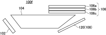
- FIG. 5 is a diagram conceptually showing another example of the aerial image display device of the present invention.
- An aerial image display device 100e shown in FIG. 5 has an image display element 102, a light guide plate 104, a reflector 120, and a light collecting optical system 106.
- the light guide plate 104 has an entrance surface 105a and an exit surface 105b that are inclined with respect to the main surface, similar to the example shown in FIG. 1.
- the image display element 102 is disposed facing the entrance surface 105a of the light guide plate 104.
- a reflector 120 is disposed facing the exit surface 105b of the light guide plate 104. In this case, the reflector 120 is disposed non-parallel to the exit surface 105b.
- the focusing optical system 106 is disposed on the optical path of the light reflected by the reflector 120. In the example shown in FIG. 5, the focusing optical system 106 is disposed at a position sandwiching the light guide plate 104 between itself and the reflector 120.
- the focusing optical system 106 is arranged substantially parallel to the main surface of the light guide plate 104, i.e., the optical axis is substantially perpendicular, and is arranged non-parallel to the reflector plate 120.
- the light emitted from the image display element 102 enters the light guide plate 104 from the entrance surface 105a and is guided through the light guide plate 104 while being totally reflected by both main surfaces (interfaces with the air layer) of the light guide plate 104.
- the light guided through the light guide plate 104 reaches the exit surface 105b, it is emitted from the exit surface 105b because the exit surface 105b is inclined at an angle that deviates from the total reflection condition.
- the light emitted from the exit surface 105b is incident on the reflector 120 and reflected.
- the reflector 120 is arranged non-parallel to the exit surface 105b so that even if the light reflected by the reflector 120 enters the light guide plate 104 again, it is reflected at an angle that does not cause total reflection at the main surface (the interface between the light guide plate 104 and the air layer). Therefore, the light reflected by the reflector 120 passes through the light guide plate 104 and enters the focusing optical system 106.
- the focusing optical system 106 focuses the incident light and forms an image irradiated by the image display element 102 in the air, which is displayed as an aerial image H.
- the reflecting section that reflects the light guided through the light guide plate and causes it to enter the focusing optical system is closer to the focusing optical system than the focal point of the focusing optical system.
- the reflecting plate 120 corresponds to the reflecting section 108. Therefore, on the optical axis of the focusing optical system 106, the reflecting plate 120 is positioned closer to the focusing optical system 106 than the focal point of the focusing optical system 106.
- the aerial image H is displayed at a position farther away from the focusing optical system 106, making it possible to display an image with a floating feel. Furthermore, because the optical path of the aerial image display device 100e does not pass through the half mirror twice, the light emitted by the image display element 102 can be used efficiently, and the brightness of the displayed aerial image H can be increased. Furthermore, because the aerial image display device 100e uses the light guide plate 104 to guide light from the image display element 102 to the focusing optical system 106, the device can be made thinner.
- the reflector 120 there are no particular limitations on the reflector 120, and a conventionally known reflector (mirror) such as a metal foil (metal plate) can be used as appropriate.
- the reflector 120 may be a partially reflective and partially transparent reflective member that reflects a portion of the incident light and transmits the remainder.
- the reflector 120 preferably has a reflectance of 25% or more, more preferably a reflectance of 50% or more, and even more preferably a reflectance of 75% or more. By making the reflector 120 have a reflectance of 25% or more, it is possible to display a brighter aerial image than an aerial image display device in which the optical path passes through a half mirror twice.
- the reflectance of the reflector 120 can be measured by measuring the reflectance of specularly reflected light according to the angle of incidence using a known reflectance measurement system, such as an absolute reflectance measurement system manufactured by JASCO Corporation.
- the reflector 120 is configured to be spaced apart from the light guide plate 104, but this is not limited thereto.
- the reflector 120 may be in contact with the exit surface 105b of the light guide plate 104, or may be attached via an adhesive layer such as OCA.
- the reflector 120 is configured to reflect the light guided to the light guide plate 104 toward the light guide plate 104, but this is not limited thereto, and the reflector 120 may be configured to reflect the incident light in a direction different from the light guide plate 104.
- the focusing optical system 106 is disposed on the optical path of the light reflected by the reflector 120.
- the focusing optical system may have multiple lenses.
- the focusing optical system 106 may have three lenses 106a to 106c.
- the configuration is not limited to inclining the entrance surface 105a and the exit surface 105b with respect to the main surface, and may have an entrance diffraction element and/or an exit diffraction element as shown in FIG. 3 and FIG. 4.
- the reflector 120 is flat, but this is not limited to this and may be configured to have at least a partially curved surface, and may be a curved mirror such as a concave mirror, convex mirror, or freeform mirror.
- a concave reflector concave mirror
- the reflector 120 by using a concave reflector (concave mirror) with an appropriate radius of curvature on the incident side as the reflector 120, distortion of the aerial image can be reduced.
- the reflectance can be measured using reflective ellipsometry, for example with a dual rotating compensator type high-speed spectroscopic ellipsometer "RC2" manufactured by J.A. Woollam. Specifically, the part of the curved mirror to be measured is fixed and placed in the reflective ellipsometer, and the specularly reflected light at that part is measured. With ellipsometry, the refractive index of the material can be measured based on the polarization state of the specularly reflected light, so the reflectance according to the angle can be calculated from the measured refractive index and the general formula for reflectance below.
- reflective ellipsometry for example with a dual rotating compensator type high-speed spectroscopic ellipsometer "RC2" manufactured by J.A. Woollam.
- the part of the curved mirror to be measured is fixed and placed in the reflective ellipsometer, and the specularly reflected light at that part is measured.
- the refractive index of the material can be measured based on
- the reflectance of the reflector 120 is measured as follows. That is, the reflectance is measured at five points on the reflector 120 in the optical path from the center of the display surface of the image display element 102, and two vertical center points and two horizontal center points of the end portions to the corresponding positions of the aerial image. The average value of the reflectance at these five points is taken as the reflectance of the reflector 120.
- the reflectance of the reflector is basically considered to be almost uniform within the surface, whether it is flat or curved. Therefore, the reflectance of the reflector 120 can be measured properly by this method. Note that since the reflectance of the reflector is basically considered to be almost uniform within the surface, only the measurement corresponding to the center of the display surface of the image display element 102 may be performed, and this measured value may be taken as the reflectance of the reflector 120.
Landscapes
- Physics & Mathematics (AREA)
- General Physics & Mathematics (AREA)
- Optics & Photonics (AREA)
- Engineering & Computer Science (AREA)
- Multimedia (AREA)
- Signal Processing (AREA)
Priority Applications (1)
| Application Number | Priority Date | Filing Date | Title |
|---|---|---|---|
| JP2025506539A JPWO2024190121A1 (https=) | 2023-03-10 | 2024-01-30 |
Applications Claiming Priority (2)
| Application Number | Priority Date | Filing Date | Title |
|---|---|---|---|
| JP2023037596 | 2023-03-10 | ||
| JP2023-037596 | 2023-03-10 |
Publications (1)
| Publication Number | Publication Date |
|---|---|
| WO2024190121A1 true WO2024190121A1 (ja) | 2024-09-19 |
Family
ID=92754822
Family Applications (1)
| Application Number | Title | Priority Date | Filing Date |
|---|---|---|---|
| PCT/JP2024/002883 Ceased WO2024190121A1 (ja) | 2023-03-10 | 2024-01-30 | 空中像表示装置 |
Country Status (2)
| Country | Link |
|---|---|
| JP (1) | JPWO2024190121A1 (https=) |
| WO (1) | WO2024190121A1 (https=) |
Citations (4)
| Publication number | Priority date | Publication date | Assignee | Title |
|---|---|---|---|---|
| JPH09243960A (ja) * | 1996-03-05 | 1997-09-19 | Nippon Telegr & Teleph Corp <Ntt> | 立体表示装置およびその駆動方法 |
| CN107390380A (zh) * | 2017-05-12 | 2017-11-24 | 上海誉沛光电科技有限公司 | 一种显示装置、导光平板及多层悬浮显示设备 |
| WO2021157585A1 (ja) * | 2020-02-04 | 2021-08-12 | 富士フイルム株式会社 | 光学素子および画像表示装置 |
| WO2021157598A1 (ja) * | 2020-02-04 | 2021-08-12 | 富士フイルム株式会社 | 光学素子および画像表示装置 |
-
2024
- 2024-01-30 WO PCT/JP2024/002883 patent/WO2024190121A1/ja not_active Ceased
- 2024-01-30 JP JP2025506539A patent/JPWO2024190121A1/ja active Pending
Patent Citations (4)
| Publication number | Priority date | Publication date | Assignee | Title |
|---|---|---|---|---|
| JPH09243960A (ja) * | 1996-03-05 | 1997-09-19 | Nippon Telegr & Teleph Corp <Ntt> | 立体表示装置およびその駆動方法 |
| CN107390380A (zh) * | 2017-05-12 | 2017-11-24 | 上海誉沛光电科技有限公司 | 一种显示装置、导光平板及多层悬浮显示设备 |
| WO2021157585A1 (ja) * | 2020-02-04 | 2021-08-12 | 富士フイルム株式会社 | 光学素子および画像表示装置 |
| WO2021157598A1 (ja) * | 2020-02-04 | 2021-08-12 | 富士フイルム株式会社 | 光学素子および画像表示装置 |
Also Published As
| Publication number | Publication date |
|---|---|
| JPWO2024190121A1 (https=) | 2024-09-19 |
Similar Documents
| Publication | Publication Date | Title |
|---|---|---|
| US12216262B2 (en) | Optical system | |
| US8016445B2 (en) | Planar light emitting element, image display element, and image display device using the same | |
| US6621533B2 (en) | Polarization separation element, a polarization conversion system, an optical element, and a projection display system | |
| US7027671B2 (en) | Polarized-light-emitting waveguide, illumination arrangement and display device comprising such | |
| US7808582B2 (en) | Illuminating apparatus wherein the plurality of polarization separating layers are disposed only to face the plurality of reflective patterns of the polarization light guide plate unit | |
| CN101395509B (zh) | 利用内全反射的偏振转向膜 | |
| JP2005504413A (ja) | 導波器、エッジ照射型照明装置及びそのような導波器又は装置を有する表示装置 | |
| US20010050815A1 (en) | Light separation device, blazed grating device, diffraction grating device, and illumination optical system | |
| TWI451142B (zh) | 光學膜 | |
| CN102906625A (zh) | 蝇眼积分器偏振转换器 | |
| WO2010061699A1 (ja) | 薄型バックライトシステムおよびこれを用いた液晶表示装置 | |
| JP2010262813A (ja) | 照明装置及び液晶表示装置 | |
| CN214375582U (zh) | 显示装置、近眼显示设备以及光波导元件 | |
| TWI446060B (zh) | 偏光轉向薄膜 | |
| WO2017083007A1 (en) | Dual-purpose, absorptive, reflective wire grid polarizer | |
| KR20010085907A (ko) | 편광조명장치, 화상표시장치, 휴대정보단말장치, 및헤드업 디스플레이 및 회절광학소자의 제조방법,편광조명장치의 제조방법, 및 화상표시장치의 제조방법 | |
| JP2005208644A (ja) | 光学システム、光源、投影ディスプレイおよび直視型ディスプレイ | |
| JPH09146092A (ja) | 照明装置およびそれを用いた液晶表示装置 | |
| US20250355143A1 (en) | Liquid crystal diffraction element and optical device | |
| US20250138227A1 (en) | Optical element | |
| JP2002014213A (ja) | ブレーズ格子素子、回折格子素子および照明光学系 | |
| JPH10282342A (ja) | 導光板、面光源装置、偏光光源装置及び液晶表示装置 | |
| WO2024190121A1 (ja) | 空中像表示装置 | |
| JPH116999A (ja) | 液晶基板の製造方法、液晶表示素子および投射型液晶表示装置 | |
| JP2011186252A (ja) | 偏光変換素子 |
Legal Events
| Date | Code | Title | Description |
|---|---|---|---|
| 121 | Ep: the epo has been informed by wipo that ep was designated in this application |
Ref document number: 24770241 Country of ref document: EP Kind code of ref document: A1 |
|
| ENP | Entry into the national phase |
Ref document number: 2025506539 Country of ref document: JP Kind code of ref document: A |
|
| WWE | Wipo information: entry into national phase |
Ref document number: 2025506539 Country of ref document: JP |
|
| NENP | Non-entry into the national phase |
Ref country code: DE |
|
| 122 | Ep: pct application non-entry in european phase |
Ref document number: 24770241 Country of ref document: EP Kind code of ref document: A1 |