WO2024190075A1 - カメラシステムおよびアプリケーションプロセッサ - Google Patents
カメラシステムおよびアプリケーションプロセッサ Download PDFInfo
- Publication number
- WO2024190075A1 WO2024190075A1 PCT/JP2024/001441 JP2024001441W WO2024190075A1 WO 2024190075 A1 WO2024190075 A1 WO 2024190075A1 JP 2024001441 W JP2024001441 W JP 2024001441W WO 2024190075 A1 WO2024190075 A1 WO 2024190075A1
- Authority
- WO
- WIPO (PCT)
- Prior art keywords
- distance measurement
- light emission
- unit
- application processor
- light
- Prior art date
- Legal status (The legal status is an assumption and is not a legal conclusion. Google has not performed a legal analysis and makes no representation as to the accuracy of the status listed.)
- Ceased
Links
Images










Classifications
-
- G—PHYSICS
- G01—MEASURING; TESTING
- G01S—RADIO DIRECTION-FINDING; RADIO NAVIGATION; DETERMINING DISTANCE OR VELOCITY BY USE OF RADIO WAVES; LOCATING OR PRESENCE-DETECTING BY USE OF THE REFLECTION OR RERADIATION OF RADIO WAVES; ANALOGOUS ARRANGEMENTS USING OTHER WAVES
- G01S17/00—Systems using the reflection or reradiation of electromagnetic waves other than radio waves, e.g. lidar systems
- G01S17/88—Lidar systems specially adapted for specific applications
- G01S17/89—Lidar systems specially adapted for specific applications for mapping or imaging
- G01S17/894—Three-dimensional [3D] imaging with simultaneous measurement of time-of-flight at a two-dimensional [2D] array of receiver pixels, e.g. time-of-flight cameras or flash lidar
-
- G—PHYSICS
- G01—MEASURING; TESTING
- G01S—RADIO DIRECTION-FINDING; RADIO NAVIGATION; DETERMINING DISTANCE OR VELOCITY BY USE OF RADIO WAVES; LOCATING OR PRESENCE-DETECTING BY USE OF THE REFLECTION OR RERADIATION OF RADIO WAVES; ANALOGOUS ARRANGEMENTS USING OTHER WAVES
- G01S7/00—Details of systems according to groups G01S13/00, G01S15/00, G01S17/00
- G01S7/48—Details of systems according to groups G01S13/00, G01S15/00, G01S17/00 of systems according to group G01S17/00
- G01S7/483—Details of pulse systems
- G01S7/484—Transmitters
-
- G—PHYSICS
- G02—OPTICS
- G02B—OPTICAL ELEMENTS, SYSTEMS OR APPARATUS
- G02B7/00—Mountings, adjusting means, or light-tight connections, for optical elements
- G02B7/28—Systems for automatic generation of focusing signals
- G02B7/40—Systems for automatic generation of focusing signals using time delay of the reflected waves, e.g. of ultrasonic waves
-
- G—PHYSICS
- G03—PHOTOGRAPHY; CINEMATOGRAPHY; ANALOGOUS TECHNIQUES USING WAVES OTHER THAN OPTICAL WAVES; ELECTROGRAPHY; HOLOGRAPHY
- G03B—APPARATUS OR ARRANGEMENTS FOR TAKING PHOTOGRAPHS OR FOR PROJECTING OR VIEWING THEM; APPARATUS OR ARRANGEMENTS EMPLOYING ANALOGOUS TECHNIQUES USING WAVES OTHER THAN OPTICAL WAVES; ACCESSORIES THEREFOR
- G03B13/00—Viewfinders; Focusing aids for cameras; Means for focusing for cameras; Autofocus systems for cameras
- G03B13/32—Means for focusing
- G03B13/34—Power focusing
- G03B13/36—Autofocus systems
-
- H—ELECTRICITY
- H04—ELECTRIC COMMUNICATION TECHNIQUE
- H04N—PICTORIAL COMMUNICATION, e.g. TELEVISION
- H04N23/00—Cameras or camera modules comprising electronic image sensors; Control thereof
- H04N23/60—Control of cameras or camera modules
- H04N23/61—Control of cameras or camera modules based on recognised objects
-
- H—ELECTRICITY
- H04—ELECTRIC COMMUNICATION TECHNIQUE
- H04N—PICTORIAL COMMUNICATION, e.g. TELEVISION
- H04N23/00—Cameras or camera modules comprising electronic image sensors; Control thereof
- H04N23/60—Control of cameras or camera modules
- H04N23/63—Control of cameras or camera modules by using electronic viewfinders
-
- H—ELECTRICITY
- H04—ELECTRIC COMMUNICATION TECHNIQUE
- H04N—PICTORIAL COMMUNICATION, e.g. TELEVISION
- H04N23/00—Cameras or camera modules comprising electronic image sensors; Control thereof
- H04N23/60—Control of cameras or camera modules
- H04N23/67—Focus control based on electronic image sensor signals
Definitions
- This technology relates to a camera system and an application processor. More specifically, this technology relates to a camera system and an application processor capable of generating focus control information based on ranging data and image data.
- This technology was developed in light of these circumstances, and aims to prevent a decline in focus accuracy caused by changes in the ranging environment.
- This technology has been made to solve the above-mentioned problems, and its first aspect is a camera system that includes a distance measurement sensor that generates distance measurement data based on measuring the distance to an object, an imaging device that generates image data based on imaging an imaging range that includes the distance measurement position of the object, and an application processor that generates focus control information for the imaging device based on the distance measurement data and the image data.
- a distance measurement sensor that generates distance measurement data based on measuring the distance to an object
- an imaging device that generates image data based on imaging an imaging range that includes the distance measurement position of the object
- an application processor that generates focus control information for the imaging device based on the distance measurement data and the image data.
- the application processor may output distance measurement control information to the distance measurement sensor, the distance measurement control information including at least one of the light emission interval, light emission intensity, light emission position, number of consecutive light emissions, light emission pulse width, and light reception position. This provides the effect of performing focus control based on the distance measurement control information.
- a prediction unit may be provided that predicts the three-dimensional position of the object based on the distance measurement data and the image data. This provides the effect of making it possible to set the focus position in accordance with the movement of the object.
- the prediction unit may predict the three-dimensional position of the object based on a three-dimensional movement vector of the object. This provides the effect of predicting the three-dimensional position of the object.
- a control unit may be provided that performs light emission control of the distance measuring sensor, light reception control of the distance measuring sensor, and focus control of the imaging device based on the prediction result of the three-dimensional position of the object. This provides the effect of performing light emission control, light reception control, and focus control while following the three-dimensional movement of the object.
- control unit may control at least one of the light emission interval, light emission intensity, light emission position, number of consecutive light emissions, light emission pulse width, and light receiving position of the distance measurement sensor based on the predicted three-dimensional position of the object. This brings about the effect of changing the distance measurement conditions in accordance with the movement of the object.
- the device may further include a display unit that displays the object and the three-dimensional movement vector of the object. This provides the effect of making the three-dimensional movement of the object visible.
- the application processor may recognize the position of the object based on image data obtained by phase-difference autofocus, and perform focus control based on the distance measurement data based on the recognition result of the object position. This provides the effect of recognizing the object position before measuring the distance to the object.
- a recognition unit may be provided that performs object recognition of the target object based on the image data generated by the imaging device. This brings about the effect of making it possible to identify the target object of focus control.
- control unit may perform focus control of the imaging device based on the object recognition result recognized by the recognition unit. This provides the effect of performing focus control with a specific object as a target.
- the second aspect may also be an application processor that includes a data input unit that inputs distance measurement data to an object and image data of an imaging range including the distance measurement position of the object, and a data output unit that outputs focus control information for imaging the object based on the distance measurement data and the image data. This provides the effect of generating focus control information based on the distance measurement data while making it possible to refer to image data.
- the application processor may output distance measurement control information including at least one of the light emission interval, light emission intensity, light emission position, number of consecutive light emissions, light emission pulse width, and light reception position. This provides the effect of performing focus control based on the distance measurement control information.
- a prediction unit may be provided that predicts the three-dimensional position of the object based on the distance measurement data and the image data. This provides the effect of making it possible to set the focus position in accordance with the movement of the object.
- the prediction unit may predict the three-dimensional position of the object based on a three-dimensional movement vector of the object. This provides the effect of predicting the three-dimensional position of the object.
- a control unit may be provided that performs light emission control of the distance measuring sensor, light reception control of the distance measuring sensor, and focus control of the imaging device based on the prediction result of the three-dimensional position of the object. This provides the effect of performing light emission control, light reception control, and focus control while following the three-dimensional movement of the object.
- control unit may control at least one of the light emission interval, light emission intensity, light emission position, number of consecutive light emissions, light emission pulse width, and light receiving position of the distance measurement sensor based on the predicted three-dimensional position of the object. This brings about the effect of changing the distance measurement conditions in accordance with the movement of the object.
- display control information for the object and the three-dimensional movement vector of the object may be output. This has the effect of making it possible to visually confirm the three-dimensional movement of the object.
- the position of the object may be recognized based on image data obtained by phase difference autofocus, and focus control based on the distance measurement data may be performed based on the recognition result of the object position. This provides the effect of recognizing the object position before measuring the distance to the object.
- a recognition unit may be provided that performs object recognition of the target object based on image data including the target object. This provides the effect of making it possible to identify the target object of focus control.
- control unit may perform focus control of the imaging device based on the object recognition result recognized by the recognition unit. This provides the effect of performing focus control with a specific object as a target.
- 1 is a block diagram showing an example of the configuration of a camera system according to a first embodiment
- 5A to 5C are diagrams illustrating an example of prediction of a three-dimensional movement vector of an object in the camera system according to the first embodiment.
- 5 is a flowchart showing an example of autofocus control of the camera system according to the first embodiment.
- 13A to 13C are diagrams illustrating an example of control of a light emitting region and a light receiving region of a camera system according to a second embodiment.
- 13A to 13C are diagrams illustrating an example of control of a light emission interval and a light emission intensity of a camera system according to a third embodiment.
- FIG. 13A and 13B are diagrams illustrating an example of control of the number of continuous flashes of a camera system according to a fourth embodiment.
- 13A to 13C are diagrams illustrating an example of control of a light emission pulse width in a camera system according to a fifth embodiment.
- 13A to 13C are diagrams illustrating an example of control of light emission positions and light reception positions of a camera system according to a sixth embodiment.
- 13A to 13C are diagrams illustrating an example of a display of an object to be autofocused by a camera system according to a seventh embodiment.
- FIG. 23 is a diagram illustrating an example of a distance measurement environment for an object to be autofocused by a camera system according to an eighth embodiment.
- FIG. 23 is a diagram illustrating an example of distance measurement processing of a camera system according to an eighth embodiment.
- 13 is a diagram showing the relationship between the distance and the correction value used in the distance measurement process of the camera system according to the eighth embodiment.
- FIG. 23 is a flowchart showing an example of distance measurement processing of a camera system according to an eighth embodiment.
- 23 is a flowchart showing an example of autofocus control of a camera system according to a ninth embodiment.
- 23A to 23C are diagrams illustrating an example of control of a light emitting area and a light receiving area of a camera system according to a tenth embodiment.
- 23 is a flowchart showing an example of control of a light emitting region and a light receiving region of a camera system according to a tenth embodiment.
- FIG. 23 is a diagram showing an example of a histogram in a first example of a ranging environment of a camera system according to an eleventh embodiment.
- FIG. 23 is a diagram showing an example of a histogram in a second example of a ranging environment of the camera system according to the eleventh embodiment.
- 23 is a flowchart showing an example of autofocus control of a camera system according to an eleventh embodiment.
- 1 is a block diagram showing a schematic configuration example of a vehicle control system
- FIG. 4 is an explanatory diagram showing an example of an installation position of an imaging unit.
- First embodiment an example of performing autofocus control according to a distance measurement result based on a predicted position of an object
- Second embodiment example of controlling light emitting area and light receiving area based on predicted position of target object
- Third embodiment example of controlling light emission interval and light emission intensity based on predicted position of target object
- Fourth embodiment example of controlling the number of consecutive flashes based on the predicted position of the target object
- Fifth embodiment example of controlling light emission pulse width based on predicted position of target object
- Sixth embodiment (example of adding margins to light emission and light reception positions controlled based on predicted position of target object) 7.
- Seventh embodiment (example of displaying an object to be autofocused based on a predicted position of the object) 8. Eighth embodiment (example of correcting distance measurement results when a transparent object is present in front of an object to be measured) 9.
- Ninth embodiment (an example of controlling autofocus according to the distance measurement result of an object recognized based on phase difference autofocus) 10.
- Tenth embodiment (example in which the light emission range and light reception range controlled based on the predicted position of the target are expanded based on the target recognition result) 11.
- Eleventh embodiment (an example of autofocus control when there is another object in front of the object to be measured) 12. Examples of applications to moving objects
- FIG. 1 is a block diagram showing an example of the configuration of a camera system according to a first embodiment.
- the camera system 100 performs autofocus control according to the distance measurement results based on the predicted position of the object.
- the camera system 100 can calculate the three-dimensional movement vector of the object based on the distance measurement data DM and image data DG to predict the position of the object to be autofocused.
- the image data DG may be RGB image data or infrared image data.
- the camera system 100 comprises a distance measurement sensor 101, an imaging device 102, an application processor 103, an IMU (Inertial Measurement Unit) 104, and a display unit 105.
- IMU Inertial Measurement Unit
- the distance measurement sensor 101 generates distance measurement data DM based on the distance to the target object.
- the distance measurement sensor 101 is, for example, a ToF (Time of Flight) sensor.
- the distance measurement sensor 101 includes a light emitting unit 111, a light receiving unit 112, a light emitting control unit 113, a light receiving control unit 114, and a readout unit 115.
- the light receiving unit 112 receives reflected light from an object onto which the distance measurement light is irradiated.
- the light receiving unit 112 includes a light receiving array unit 118.
- the light receiving array unit 118 includes a plurality of light receiving regions 119.
- the light receiving regions 119 may be arranged in a matrix in the row and column directions. Each light receiving region 119 is capable of receiving light individually.
- Each light receiving region 119 may include a SPAD (Single Photon Avalanche Diode).
- the light receiving unit 112 may also include a TDC (Time to Digital Converter) and a histogram generation unit.
- the histogram generation unit can show the relationship between the time difference between light emission and light reception and the number of reactions in each light receiving region 119.
- the light emission control unit 113 controls the light emission of the light emitting unit 111 based on the distance measurement control information DS.
- the light emission control unit 113 can control the light emission interval, light emission intensity, light emission position, number of consecutive light emissions, and light emission pulse width of the light emitting unit 111 based on the distance measurement control information DS.
- the light emitting area 117 to be activated can be selected.
- the light receiving control unit 114 controls the light receiving of the light receiving unit 112 based on the distance measurement control information DS. For example, the light receiving control unit 114 can control the light receiving position of the light receiving unit 112 based on the distance measurement control information DS. In controlling the light receiving position of the light receiving unit 112, the light receiving area 119 to be activated can be selected.
- the readout unit 115 reads out the distance measurement data DM of each light receiving area 119 from the light receiving array unit 118 and outputs it to the application processor 103.
- the imaging device 102 generates image data DG based on an image of an imaging range including the distance measurement position of the object.
- the imaging device 102 includes an imaging unit 121, an optical system 122, a readout unit 123, and a lens control unit 124.
- the readout unit 123 reads out image data DG from the pixel array unit 126 and outputs it to the application processor 103.
- the image data DG can be constructed based on pixel data read out from each pixel 127.
- the lens control unit 124 performs focus control of the light received by the imaging unit 121 by controlling the position of the optical system 122 based on the focus control information DF.
- the application processor 103 generates focus control information DF for the imaging device 102 and distance measurement control information DS for the distance measurement sensor 101 based on the distance measurement data DM and image data DG.
- the distance measurement control information DS can include at least one of the light emission interval, light emission intensity, light emission position, number of consecutive light emissions, light emission pulse width, and light receiving position of the distance measurement sensor 101.
- the application processor 103 includes a data output unit 131, a data input unit 132, a calculation unit 133, and a memory unit 134.
- the data output unit 131 outputs the distance measurement control information DS to the distance measurement sensor 101, and outputs the focus control information DF to the imaging device 102.
- the distance measurement control information DS and focus control information DF output via the data output unit 131 can be input to the data output unit 131 from the calculation unit 133.
- the data input unit 132 inputs the distance measurement data DM output from the distance measurement sensor 101 and the image data DG output from the imaging device 102.
- the distance measurement data DM and image data DG input via the data input unit 132 can be stored in the memory unit 134.
- Calculation unit 133 generates distance measurement control information DS and focus control information DF based on distance measurement data DM and image data DG. Calculation unit 133 can access memory unit 134 and store the results of calculations by calculation unit 133 in memory unit 134 or read data from memory unit 134. Calculation unit 133 includes control unit 141, prediction unit 142, and recognition unit 143.
- the prediction unit 142 predicts the three-dimensional position of the object based on the ranging data DM and image data DG. To predict the three-dimensional position of the object, the prediction unit 142 can calculate the three-dimensional movement vector of the object based on the ranging data DM and image data DG. At this time, the prediction unit 142 can predict the three-dimensional position of the object in the next frame from the ranging data DM and image data DG of multiple frames.
- the recognition unit 143 performs object recognition of the target object based on the image data DG generated by the imaging device 102. In object recognition of the target object, the recognition unit 143 can recognize the shape, pattern, and color of the target object.
- the memory unit 134 stores various data related to distance measurement and imaging.
- the memory unit 134 may include semiconductor memory such as SRAM (Static Random Access Memory) or DRAM (Dynamic Random Access Memory), or may include a storage device such as a hard disk device or SSD (Solid State Drive).
- the memory unit 134 stores acquired data 151, a processing program 155, and setting information 156.
- the acquired data 151 includes distance measurement data 152, image data 153, and frame acquisition time information 154.
- the processing program 155 includes a program executed by the application processor 103.
- the setting information 156 includes setting information used for distance measurement and imaging.
- the IMU 104 detects three-dimensional inertial motion (translational motion and rotational motion in three axial directions).
- the IMU 104 may include, for example, an acceleration sensor, a rotational angular acceleration sensor, a gyro sensor, a magnetic field sensor, an air pressure sensor, or a temperature sensor.
- the display unit 105 displays the object to be measured, the three-dimensional movement vector of the object to be measured, a distance image, a user interface screen, and the like.
- the display unit 105 may be a liquid crystal display device or an organic EL display device.
- the application processor 103 can output display control information of the object to be measured and the three-dimensional movement vector of the object to the display unit 105.
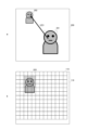
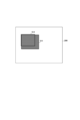
- FIG. 2 shows an example of a prediction of a three-dimensional movement vector of an object in a camera system according to the first embodiment.
- the imaging device 102 generates a two-dimensional image 200.
- the prediction unit 142 predicts the three-dimensional position of the object 202 in the next frame based on the ranging data DM and image data DG of the object 201 in multiple past frames.
- the prediction unit 142 can calculate a three-dimensional movement vector VEC from the object 201 to the object 202 based on the ranging data DM and image data DG of the object 201 in multiple past frames.
- the control unit 141 sets the light receiving range 203 for the next frame based on the predicted position of the object 202 in the next frame. At this time, the control unit 141 activates the light receiving areas 119 included in the light receiving range 203. This makes it possible to measure the distance to the object 202 in the next frame while deactivating the light receiving areas 119 outside the light receiving range 203, thereby reducing power consumption without reducing the accuracy of distance measurement.
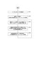
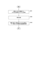
- FIG. 3 is a flowchart showing an example of autofocus control of the camera system according to the first embodiment.
- the user specifies an object to be focused on (S101).
- the user may touch the object on the display screen of the display unit 105.
- the camera system 100 refers to the image data DG and performs autofocusing of the imaging device 102 based on the distance measurement data DM of the object (S102).
- the camera system 100 can check whether the object is within the angle of view of the imaging device 102 and whether there is an obstacle in front of the object.
- the camera system 100 predicts the three-dimensional position of the object 202 in the next frame based on the distance measurement data DM and image data DG of the object 201 in multiple past frames (S103).
- the camera system 100 generates distance measurement control information DS including at least one of the light emission interval, light emission intensity, light emission position, number of consecutive light emissions, light emission pulse width, and light receiving position of the distance measurement sensor 101 (S104).
- the camera system 100 measures the distance to the object based on the distance measurement control information DS, and performs autofocusing of the image capture device 102 based on the distance measurement data DM of the object obtained by the distance measurement (S105).
- the application processor 103 can output focus control information DF to the image capture device 102.
- the camera system 100 performs autofocus control according to the distance measurement results obtained based on the predicted position of the object. This allows autofocus to be performed based on a three-dimensionally optimized distance measurement range based on the position of the object and the distance to the object, making it possible to reduce power consumption without reducing focus accuracy.
- Second embodiment In the first embodiment described above, autofocusing is performed based on the distance measurement results obtained from the light receiving range 203 set based on the predicted position of the target in the next frame.
- the light emission range and light receiving range are set based on the predicted position of the target in the next frame, and autofocusing is performed based on the distance measurement results obtained from the settings.
- FIG. 4 shows an example of control of the light-emitting area and the light-receiving area of the camera system according to the second embodiment.
- the prediction unit 142 predicts the three-dimensional position of the object in the next frame based on the distance measurement data DM and image data DG of the object in multiple past frames.
- the control unit 141 sets the light receiving range 211 for the next frame based on the predicted position of the object in the next frame, as shown in a in the figure.
- the light receiving range 211 can include the light receiving position of reflected light from the predicted position of the object in the next frame.
- the control unit 141 activates the light receiving region 119 included in the light receiving range 211.
- the control unit 141 also sets the light emission range 212 for the next frame based on the predicted position of the object in the next frame, as shown in b in the figure.
- the light emission range 212 can include the light emission position of the distance measurement light that is irradiated onto the predicted position of the object in the next frame. At this time, the control unit 141 activates the light emission region 117 included in the light emission range 212.
- the camera system 100 sets the light receiving range 211 and the light emitting range 212 based on the predicted position of the object in the next frame, and performs autofocusing based on the distance measurement results according to these settings. This makes it possible to limit the distance measurement range based on the position of the object and the distance to the object, while performing autofocusing based on the distance measurement results that involve this limitation, making it possible to reduce power consumption without reducing focus accuracy.
- the light receiving range 211 and the light emitting range 212 are set based on the predicted position of the object in the next frame, and autofocus is performed based on the distance measurement results according to the settings.
- the light emission interval and light emission intensity of the distance measuring sensor 101 are set based on the predicted position of the object in the next frame, and autofocus is performed based on the distance measurement results according to the settings.
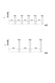
- FIG. 5 shows an example of control of the light emission interval and light emission intensity of a camera system according to the third embodiment.
- the prediction unit 142 predicts the three-dimensional position of the object in the next frame based on the distance measurement data DM and image data DG of the object in multiple past frames.
- the control unit 141 sets the light emission interval VA1 and light emission intensity PW1 for the next frame based on the predicted position of the object in the next frame. At this time, if the object to be measured is close, the control unit 141 can reduce the light emission interval VA1 and light emission intensity PW1.
- the attenuation of the reflected light from the object is small, so the light emission intensity PW1 of the light-emitting unit 111 may be small.
- the timing of the arrival of the reflected light from the object is early, and there are few bins of the histogram used in the distance measurement, so the light emission interval VA1 of the light-emitting unit 111 may be short.
- the control unit 141 also sets the light emission interval VA2 and light emission intensity PW2 for the next frame based on the predicted position of the target object in the next frame, as shown in b in the figure. At this time, if the target object is far away, the control unit 141 can increase the light emission interval VA2 and light emission intensity PW2.
- the camera system 100 sets the light emission interval and light emission intensity based on the predicted position of the object in the next frame, and performs autofocusing based on the distance measurement results according to these settings. This makes it possible to optimize the distance measurement conditions based on the object's position and the distance to the object, while performing autofocusing based on the optimized distance measurement results, making it possible to reduce power consumption without reducing focus accuracy.
- the light emission interval and light emission intensity of the distance measuring sensor 101 are set based on the predicted position of the object in the next frame, and autofocus is performed based on the distance measurement result according to the settings.
- the number of continuous light emissions of the distance measuring sensor 101 is set based on the predicted position of the object in the next frame, and autofocus is performed based on the distance measurement result according to the settings.
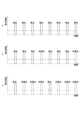
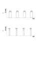
- FIG. 6 shows an example of control of the number of consecutive flashes in a camera system according to the fourth embodiment.
- the prediction unit 142 predicts the three-dimensional position of the object in the next frame based on the distance measurement data DM and image data DG of the object in multiple past frames. At this time, in order to improve the S/N ratio, the control unit 141 can increase the number of consecutive emissions as the predicted position of the object becomes farther away.
- control unit 141 sets the number of consecutive flashes to 8, as shown in a in the figure.
- control unit 141 sets the number of consecutive flashes to 3, as shown in b in the figure.
- control unit 141 sets the number of continuous flashes to 1, as shown by c in the figure.
- the camera system 100 sets the number of continuous flashes based on the predicted position of the object in the next frame, and performs autofocusing based on the distance measurement results according to the setting. This makes it possible to optimize the distance measurement conditions based on the object's position and the distance to the object, while performing autofocusing based on the optimized distance measurement results, making it possible to reduce power consumption without reducing focus accuracy.
- the number of continuous light emissions of the distance measuring sensor 101 is set based on the predicted position of the object in the next frame, and autofocus is performed based on the distance measurement results according to the setting.
- the light emission pulse width of the distance measuring sensor 101 is set based on the predicted position of the object in the next frame, and autofocus is performed based on the distance measurement results according to the setting.
- FIG. 7 shows an example of controlling the light emission pulse width of a camera system according to the fifth embodiment.
- the prediction unit 142 predicts the three-dimensional position of the object in the next frame based on the distance measurement data DM and image data DG of the object in multiple past frames.
- the time width of one bin of the histogram used for distance measurement may increase.
- the control unit 141 can increase the light emission pulse width of the light emission unit 111 in accordance with the increase in the time width of one bin of the histogram.
- the light emission pulse width > histogram bin a distance measurement accuracy equal to or less than the time resolution of the histogram bin can be obtained based on a center of gravity calculation of the counts of multiple bins.
- control unit 141 sets the light emission pulse width WT1 for the next frame to be wide based on the predicted position of the object in the next frame, as shown in a in the figure.
- the camera system 100 sets the light emission pulse width based on the predicted position of the object in the next frame, and performs autofocusing based on the distance measurement results according to that setting. This makes it possible to optimize the distance measurement conditions based on the object's position and the distance to the object, while performing autofocusing based on the optimized distance measurement results, making it possible to reduce power consumption without reducing focus accuracy.
- FIG. 8 shows an example of control of the light emission position and the light reception position of a camera system according to the sixth embodiment.
- the prediction unit 142 predicts the three-dimensional position of the object 202 in the next frame based on the distance measurement data DM and image data DG of the object 201 in multiple past frames. At this time, the prediction unit 142 can set a prediction range 204 with a margin added to the predicted position of the object 202.
- control unit 141 sets the light receiving range 203 and the light emitting range 212 for the next frame based on the predicted range 204 of the object 202 to which a margin has been added.
- the control unit 141 can also set the light emitting interval and the light emitting intensity based on the predicted range 204 of the object 202 to which a margin has been added. For example, the control unit 141 can set the light emitting interval and the light emitting intensity to correspond to a distance 1.2 times the predicted position of the object 202 in the depth direction.
- the camera system 100 provides a margin in the light receiving range 203 and the light emitting range 212 that are set based on the predicted position of the object in the next frame. This allows for a margin in the distance measurement conditions that are optimized based on the position of the object and the distance to the object, making it possible to reduce power consumption while improving the stability of focus control.
- a three-dimensional movement vector of the object is calculated based on the distance measurement data DM and image data DG.
- this seventh embodiment it is possible to display an object that moves according to a three-dimensional movement vector calculated based on the distance measurement data DM and image data DG.
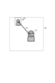
- the display screen 300 displays an object 301 to be autofocused and its predicted position 302.
- a three-dimensional movement vector VEC1 indicating the predicted position 302 of the object 301 to be autofocused and its movement speed may also be displayed on the display screen 300.
- the display screen 300 may display the object 311 to be autofocused and its predicted position 312 in a three-dimensional virtual space.
- This three-dimensional virtual space may be a captured image of the periphery of the object 311 and its predicted position 312, or the periphery of the object 311 and its predicted position 312 may be three-dimensionally illustrated, or it may be the metaverse.
- the object 311 to be autofocused and its predicted position 312 may be displayed as an animation in the three-dimensional virtual space.
- a three-dimensional movement vector VEC2 and a movement speed indicating the predicted position 312 of the object 311 to be autofocused may be displayed in the three-dimensional virtual space.
- the distance measurement conditions are set based on the predicted position of the object in the next frame, and autofocus is performed based on the distance measurement results according to the distance measurement conditions.
- the distance measurement results are corrected when a transparent object is present in front of the object to be measured.
- FIG. 10 shows an example of the distance measurement environment for an object to be autofocused by a camera system according to the eighth embodiment.
- a transparent body 401 is assumed to be located in front of an object 402 to be autofocused.
- the transparent body 401 is, for example, a glass plate such as a window.
- the distance measurement light LML emitted from the light-emitting unit 111 passes through the transparent body 401 and is irradiated onto the object 402, and the reflected light LRF1 reflected by the object 402 enters the light-receiving unit 112 via the transparent body 401.
- the distance measurement light LML emitted from the light-emitting unit 111 is reflected by the transparent body 401, and the reflected light LRF2 reflected by the transparent body 401 enters the light-receiving unit 112.
- the intensity of the reflected light LRF2 may be stronger than the intensity of the reflected light LRF1.
- the distance to the object 402 is calculated from the peak position of the histogram of the number of SPAD reactions based on the reception of each reflected light LRF1 and LRF2, an erroneous distance measurement may occur.
- FIG. 11 shows an example of distance measurement processing of a camera system according to the eighth embodiment
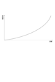
- FIG. 12 shows the relationship between the distance and the correction value used in the distance measurement processing of the camera system according to the eighth embodiment.
- the distance measurement sensor 101 when the distance measurement sensor 101 receives reflected light LRF1 and LRF2 from the object 402 and the transparent body 401, it generates a histogram HSA of the number of SPAD reactions based on the reception of each reflected light LRF1 and LRF2.
- a peak P1A of the number of SPAD reactions based on reception of reflected light LRF1 from the transparent body 401, and a peak P2A of the number of SPAD reactions based on reception of reflected light LRF2 from the object 402 are generated. Since the transparent body 401 is closer to the distance measurement sensor 101 than the object 402, the height of peak P1A is higher than the height of peak P2A. At this time, the distance measurement sensor 101 refers to image data DG that includes the object 402 in its imaging range. Then, if the presence of another object in front of the object 402 cannot be confirmed from the image data DG, the application processor 103 can determine that the transparent body 401 corresponding to peak P1A is in front of the object 402.
- the application processor 103 determines that a transparent body 401 is present in front of the object 402, it performs background light processing. In this background light processing, the application processor 103 calculates the average count value AVE of all bins of the histogram HSA. The application processor 103 then subtracts the average count value AVE from the histogram HSA to generate a histogram HSB as shown in FIG. 11b. In the histogram HSB, a peak P1B corresponding to the transparent body 401 appears at a position equivalent to the distance of peak P1A, and a peak P2B corresponding to the object 402 appears at a position equivalent to the distance of peak P2A.
- the application processor 103 then corrects the histogram HSB based on a correction value that depends on the distance from the distance sensor 101, and generates a histogram HSC, as shown in FIG. 11c.
- the correction value that depends on the distance from the distance sensor 101 can be given by a nonlinear function with distance as a parameter. At this time, the light intensity attenuates as the square of the distance from the distance sensor 101. For this reason, for example, as shown in FIG. 12, the correction value that depends on the distance from the distance sensor 101 can use a correction value that is proportional to the square of the distance corresponding to each bin of the histogram HSB.
- peak P1C corresponding to the transparent body 401 appears at a position at the same distance as peak P1B
- peak P2C corresponding to the object 402 appears at a position at the same distance as peak P2B.
- the height of peak P1C corresponding to the transparent body 401 is lower than the height of peak P2C corresponding to the object 402. Therefore, the distance measurement sensor 101 can calculate the distance to the object 402 based on the position of peak P2C in the histogram HSC.
- FIG. 13 is a flowchart showing an example of distance measurement processing of a camera system according to the eighth embodiment.
- the application processor 103 obtains a histogram of the number of SPAD reactions for each distance from the distance sensor 101 (S201). At this time, the application processor 103 can associate the distance from the distance sensor 101 with the position of the bin in the histogram.
- the application processor 103 performs background light processing of the histogram acquired in S201 (S202).
- the histogram average count value may be subtracted from the histogram.
- the application processor 103 corrects the histogram after background light processing based on a correction value that depends on the distance from the distance measurement sensor 101. Then, the application processor 103 obtains the distance measurement result of the object based on peak detection of the corrected histogram (S203).
- the histogram is corrected when a transparent body 401 is in front of the object 402 whose distance is being measured, based on a correction value that depends on the distance from the distance measurement sensor 101. This makes it possible to improve the accuracy of distance measurement when a transparent body 401 is in front of the object 402 whose distance is being measured.
- FIG. 14 is a flowchart showing an example of autofocus control of a camera system according to the ninth embodiment.
- the camera system 100 captures an image of an object based on phase-difference autofocus (S301).
- the imaging range of this object can be set to the entire angle of view.
- the power consumption of imaging with the entire angle of view set as the imaging range can be less than the power consumption of ranging with the entire angle of view set as the ranging range.
- the application processor 103 recognizes the position of the autofocus target based on the object imaged using phase difference autofocus (S302).
- the application processor 103 controls the light emitting position and light receiving position of the distance measurement sensor 101 based on the position of the autofocus target (S303). At this time, by limiting the light emitting position and light receiving position of the distance measurement sensor 101 based on the position of the autofocus target, it is possible to reduce power consumption compared to the case where the entire angle of view is set as the distance measurement range.
- the camera system 100 performs autofocus on the imaging device 102 based on the distance measurement results from the distance measurement sensor 101 (S304).
- the light emitting position and the light receiving position of the distance measuring sensor 101 are controlled based on the predicted position of the object.
- the light emitting range and the light receiving range controlled based on the predicted position of the object are expanded based on the recognition result of the object.
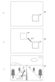
- FIG. 15 shows an example of control of the light-emitting area and the light-receiving area of a camera system according to the tenth embodiment.
- the camera system 100 sets the light receiving range 351 of the distance measurement sensor 101 in the light receiving array unit 118 based on the predicted position of the autofocus target. The camera system 100 then measures the distance of the autofocus target while making the light receiving range 351 of the distance measurement sensor 101 follow the movement of the autofocus target. At this time, the camera system 100 performs object recognition of the autofocus target and determines whether the object recognized as the autofocus target is within the light receiving range 351 of the distance measurement sensor 101. If the object recognized as the autofocus target is not within the light receiving range 351 of the distance measurement sensor 101, the camera system 100 switches the light receiving range to the entire surface of the light receiving array unit 118.
- the light receiving range is switched to the entire surface of the light receiving array unit 118. If the object recognized as the autofocus target is not within the light emitting range of the distance measuring sensor 101, the light emitting range may be switched to the entire surface of the light emitting array unit 116.
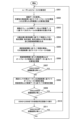
- FIG. 16 is a flowchart showing an example of control of the light-emitting area and the light-receiving area of the camera system according to the tenth embodiment.
- the camera system 100 performs the processing of S101 to S105 of the first embodiment described above.
- the application processor 103 recognizes the object based on the distance measurement data DM according to the distance measurement control information DS and the autofocus controlled image data DG (S406).
- the application processor 103 determines whether the object recognition result of S402 and the object recognition result of S406 are equal to each other (S407). If the object recognition result of S402 and the object recognition result of S406 are equal to each other, the application processor 103 returns to the process of S403. On the other hand, if the object recognition result of S402 and the object recognition result of S406 are not equal to each other, the application processor 103 proceeds to the process of S408.
- the application processor 103 sets the light emission range and light reception range of the distance measurement sensor 101 to the entire surface of the pixel array section 126, and searches for the position of the target object from the feature amount obtained at this time (S408).
- the application processor 103 determines whether the position of the object has been found within the entire surface of the pixel array section 126 (S409). If the position of the object has been found within the entire surface of the pixel array section 126, the application processor 103 returns to the process of S403. On the other hand, if the position of the object has not been found within the entire surface of the pixel array section 126, the application processor 103 returns to the process of S401.
- the camera system 100 expands the light emission range and light reception range controlled based on the predicted position of the autofocus target based on the recognition result of the autofocus target. This makes it possible to perform distance measurement by following an autofocus target that has moved beyond the light emission range and light reception range while limiting the light emission range and light reception range controlled based on the predicted position of the autofocus target.
- the distance to the autofocus target is measured while tracking the autofocus target based on the recognition result of the autofocus target.
- the distance to the autofocus target is measured while confirming the autofocus target based on the recognition result of the autofocus target.
- FIG. 17 is a diagram showing a first example of a distance measurement environment for an object to be autofocused by a camera system according to an eleventh embodiment.
- the two-dimensional image 200 generated by the imaging device 102 shows a distant autofocus target 502 and a nearby non-autofocus target 501.
- FIG. 18 shows an example of a histogram in a first example of a distance measurement environment of a camera system according to the eleventh embodiment.
- the distance measurement sensor 101 generates a histogram HS1 of the number of SPAD reactions based on the reception of reflected light from a distant autofocus target 502 and a nearby non-autofocus target 501.
- a peak P1 of the number of SPAD reactions based on receiving reflected light from a nearby non-autofocus target 501 and a peak P2 of the number of SPAD reactions based on receiving reflected light from a distant autofocus target 502 occur.
- the height of peak P1 is higher than the height of peak P2.
- the application processor 103 performs object recognition for the non-autofocus target 501 identified by peak P1.
- the application processor 103 discards the distance measurement result of the non-autofocus target 501 identified by peak P1. Then, the application processor 103 performs autofocus control for the autofocus target 502 based on the distance measurement result of the autofocus target 502 identified by peak P2.
- FIG. 19 is a diagram showing a second example of the distance measurement environment for an object to be autofocused by the camera system according to the eleventh embodiment.
- FIG. 20 shows an example of a histogram in a second example of a distance measurement environment of a camera system according to the eleventh embodiment.
- the distance measurement sensor 101 generates a histogram HS2 of the number of SPAD reactions based on the reception of reflected light from a distant autofocus target 512 and a nearby non-autofocus target 511.
- a peak P1 occurs in the number of SPAD reactions based on the reception of reflected light from the nearby non-autofocus target 511.
- a peak P2 does not occur in the number of SPAD reactions based on the reception of reflected light from the distant autofocus target 502.
- the application processor 103 performs object recognition for the non-autofocus target 511 identified by the peak P1.
- the application processor 103 discards the distance measurement result of the non-autofocus target 511 identified by the peak P1. Then, the application processor 103 repeats imaging and distance measurement for multiple frames to check whether a peak P2 occurs for the autofocus target 512.
- FIG. 21 is a flowchart showing an example of autofocus control of a camera system according to the eleventh embodiment.
- the camera system 100 performs the processing of S401 to S407 of the tenth embodiment described above.
- the application processor 103 performs autofocus control based on the distance measurement result from the second peak of the distance measurement sensor 101. Note that the second peak is the second highest peak in the histogram. Then, the application processor 103 recognizes the focus target based on the distance measurement result and the image data (S508).
- the application processor 103 determines whether the object recognition result of S502 and the object recognition result of S508 are equal to each other (S509). Note that instead of determining whether the object recognition result of S502 and the object recognition result of S508 are equal to each other, the application processor 103 may determine whether the second peak of S508 is smaller than a predetermined value. If the object recognition result of S502 and the object recognition result of S508 are equal to each other, the application processor 103 returns to the process of S503. On the other hand, if the object recognition result of S502 and the object recognition result of S508 are not equal to each other, the application processor 103 proceeds to the process of S510.
- the application processor 103 executes the processes from S504 to S509 a predetermined number of times (S510).
- the application processor 103 determines whether the object recognition result of S502 and the object recognition result of S510 are equal to each other (S511). If the object recognition result of S502 and the object recognition result of S510 are equal to each other, the application processor 103 returns to the process of S503. On the other hand, if the object recognition result of S502 and the object recognition result of S510 are not equal to each other, the application processor 103 returns to the process of S501.
- the distance to the autofocus target is measured while confirming the autofocus target based on the recognition result of the autofocus target. This makes it possible to perform autofocus control on the autofocus target even if there is a non-autofocus target in front of the autofocus target.
- the technology according to the present disclosure can be applied to various products.
- the technology according to the present disclosure may be realized as a device mounted on any type of moving body such as an automobile, an electric vehicle, a hybrid electric vehicle, a motorcycle, a bicycle, a personal mobility device, an airplane, a drone, a ship, or a robot.
- FIG. 22 is a block diagram showing a schematic configuration example of a vehicle control system, which is an example of a mobile object control system to which the technology disclosed herein can be applied.
- the vehicle control system 12000 includes a plurality of electronic control units connected via a communication network 12001.
- the vehicle control system 12000 includes a drive system control unit 12010, a body system control unit 12020, an outside vehicle information detection unit 12030, an inside vehicle information detection unit 12040, and an integrated control unit 12050.
- Also shown as functional components of the integrated control unit 12050 are a microcomputer 12051, an audio/video output unit 12052, and an in-vehicle network I/F (interface) 12053.
- the drive system control unit 12010 controls the operation of devices related to the drive system of the vehicle according to various programs.
- the drive system control unit 12010 functions as a control device for a drive force generating device for generating the drive force of the vehicle, such as an internal combustion engine or a drive motor, a drive force transmission mechanism for transmitting the drive force to the wheels, a steering mechanism for adjusting the steering angle of the vehicle, and a braking device for generating a braking force for the vehicle.
- the body system control unit 12020 controls the operation of various devices installed in the vehicle body according to various programs.
- the body system control unit 12020 functions as a control device for a keyless entry system, a smart key system, a power window device, or various lamps such as headlamps, tail lamps, brake lamps, turn signals, and fog lamps.
- radio waves or signals from various switches transmitted from a portable device that replaces a key can be input to the body system control unit 12020.
- the body system control unit 12020 accepts the input of these radio waves or signals and controls the vehicle's door lock device, power window device, lamps, etc.
- the outside-vehicle information detection unit 12030 detects information outside the vehicle equipped with the vehicle control system 12000.
- the image capturing unit 12031 is connected to the outside-vehicle information detection unit 12030.
- the outside-vehicle information detection unit 12030 causes the image capturing unit 12031 to capture images outside the vehicle, and receives the captured images.
- the outside-vehicle information detection unit 12030 may perform object detection processing or distance detection processing for people, cars, obstacles, signs, or characters on the road surface, based on the received images.
- the imaging unit 12031 is an optical sensor that receives light and outputs an electrical signal according to the amount of light received.
- the imaging unit 12031 can output the electrical signal as an image, or as distance measurement information.
- the light received by the imaging unit 12031 may be visible light, or may be invisible light such as infrared light.
- the in-vehicle information detection unit 12040 detects information inside the vehicle.
- a driver state detection unit 12041 that detects the state of the driver is connected.
- the driver state detection unit 12041 includes, for example, a camera that captures an image of the driver, and the in-vehicle information detection unit 12040 may calculate the driver's degree of fatigue or concentration based on the detection information input from the driver state detection unit 12041, or may determine whether the driver is dozing off.
- the microcomputer 12051 can calculate control target values for the driving force generating device, steering mechanism, or braking device based on information inside and outside the vehicle acquired by the outside vehicle information detection unit 12030 or the inside vehicle information detection unit 12040, and output control commands to the drive system control unit 12010.
- the microcomputer 12051 can perform cooperative control aimed at realizing the functions of an Advanced Driver Assistance System (ADAS), including vehicle collision avoidance or impact mitigation, following driving based on the distance between vehicles, maintaining vehicle speed, vehicle collision warning, or vehicle lane departure warning.
- ADAS Advanced Driver Assistance System
- the microcomputer 12051 can also perform cooperative control for the purpose of autonomous driving, which allows the vehicle to travel autonomously without relying on the driver's operation, by controlling the driving force generating device, steering mechanism, braking device, etc. based on information about the surroundings of the vehicle acquired by the outside vehicle information detection unit 12030 or the inside vehicle information detection unit 12040.
- the microcomputer 12051 can also output control commands to the body system control unit 12020 based on information outside the vehicle acquired by the outside-vehicle information detection unit 12030. For example, the microcomputer 12051 can control the headlamps according to the position of a preceding vehicle or an oncoming vehicle detected by the outside-vehicle information detection unit 12030, and perform cooperative control aimed at preventing glare, such as switching high beams to low beams.
- the audio/image output unit 12052 transmits at least one output signal of audio and image to an output device capable of visually or audibly notifying the occupants of the vehicle or the outside of the vehicle of information.
- an audio speaker 12061, a display unit 12062, and an instrument panel 12063 are exemplified as output devices.
- the display unit 12062 may include, for example, at least one of an on-board display and a head-up display.
- FIG. 23 shows an example of the installation position of the imaging unit 12031.
- the imaging unit 12031 includes imaging units 12101, 12102, 12103, 12104, and 12105.
- FIG. 23 shows an example of the imaging ranges of the imaging units 12101 to 12104.
- Imaging range 12111 indicates the imaging range of the imaging unit 12101 provided on the front nose
- imaging ranges 12112 and 12113 indicate the imaging ranges of the imaging units 12102 and 12103 provided on the side mirrors, respectively
- imaging range 12114 indicates the imaging range of the imaging unit 12104 provided on the rear bumper or back door.
- an overhead image of the vehicle 12100 viewed from above is obtained by superimposing the image data captured by the imaging units 12101 to 12104.
- At least one of the imaging units 12101 to 12104 may have a function of acquiring distance information.
- at least one of the imaging units 12101 to 12104 may be a stereo camera consisting of multiple imaging elements, or an imaging element having pixels for phase difference detection.
- the microcomputer 12051 classifies and extracts three-dimensional object data on three-dimensional objects, such as two-wheeled vehicles, ordinary vehicles, large vehicles, pedestrians, utility poles, and other three-dimensional objects, based on the distance information obtained from the imaging units 12101 to 12104, and can use the data to automatically avoid obstacles.
- the microcomputer 12051 distinguishes obstacles around the vehicle 12100 into obstacles that are visible to the driver of the vehicle 12100 and obstacles that are difficult to see.
- the microcomputer 12051 determines the collision risk, which indicates the risk of collision with each obstacle, and when the collision risk is equal to or exceeds a set value and there is a possibility of a collision, it can provide driving assistance for collision avoidance by outputting an alarm to the driver via the audio speaker 12061 or the display unit 12062, or by forcibly decelerating or steering to avoid a collision via the drive system control unit 12010.
- At least one of the imaging units 12101 to 12104 may be an infrared camera that detects infrared rays.
- the microcomputer 12051 can recognize a pedestrian by determining whether or not a pedestrian is present in the captured image of the imaging units 12101 to 12104. The recognition of such a pedestrian is performed, for example, by a procedure of extracting feature points in the captured image of the imaging units 12101 to 12104 as infrared cameras, and a procedure of performing pattern matching processing on a series of feature points that indicate the contour of an object to determine whether or not it is a pedestrian.
- the audio/image output unit 12052 controls the display unit 12062 to superimpose a rectangular contour line for emphasis on the recognized pedestrian.
- the audio/image output unit 12052 may also control the display unit 12062 to display an icon or the like indicating a pedestrian at a desired position.
- the technology disclosed herein can be applied to the imaging unit 12031 of the configuration described above.
- the camera system 100 described above can be applied to the imaging unit 12031.
- the above-described embodiment shows an example for realizing the present technology, and there is a corresponding relationship between the matters in the embodiment and the matters specifying the invention in the claims. Similarly, there is a corresponding relationship between the matters specifying the invention in the claims and the matters in the embodiment of the present technology that have the same name.
- the present technology is not limited to the embodiment, and can be realized by making various modifications to the embodiment without departing from the gist of the technology.
- the effects described in this specification are merely examples and are not limiting, and other effects may also be present.
- the present technology can also be configured as follows. (1) a distance measurement sensor that generates distance measurement data based on distance measurement to an object; an imaging device that generates image data based on an image of an imaging range including the distance measurement position of the object; and an application processor that generates focus control information for the imaging device based on the distance measurement data and the image data. (2) The camera system described in (1) in which the application processor outputs ranging control information to the ranging sensor, the ranging control information including at least one of the light emission interval, light emission intensity, light emission position, number of continuous lights emission, light emission pulse width, and light receiving position. (3) The camera system according to (1) or (2), further comprising a prediction unit that predicts a three-dimensional position of the object based on the distance measurement data and the image data.
- a camera system as described in (3) or (4) comprising a control unit that performs light emission control of the ranging sensor, light reception control of the ranging sensor, and focus control of the imaging device based on the predicted result of the three-dimensional position of the object.
- the control unit of the camera system described in (5) controls at least one of the light emission interval, light emission intensity, light emission position, number of consecutive emissions, light emission pulse width, and light receiving position of the ranging sensor based on the predicted result of the three-dimensional position of the object.
- the control unit performs focus control of the imaging device based on an object recognition result recognized by the recognition unit.
- the application processor according to (11) outputs ranging control information including at least one of a light emission interval, a light emission intensity, a light emission position, a number of continuous lights emission times, a light emission pulse width, and a light receiving position.
- the application processor according to (11) or (12) further comprising a prediction unit that predicts a three-dimensional position of the object based on the distance measurement data and the image data.
- the application processor described in (14) is provided with a control unit that performs light emission control of the ranging sensor, light reception control of the ranging sensor, and focus control of the imaging device based on the predicted result of the three-dimensional position of the object.
- the control unit of the application processor described in (15) controls at least one of the light emission interval, light emission intensity, light emission position, number of consecutive emissions, light emission pulse width, and light receiving position of the distance measurement sensor based on the predicted result of the three-dimensional position of the target object.
- Camera system 101 Distance measurement sensor 102 Imaging device 103 Application processor 104 IMU 105 Display unit 111 Light emitting unit 112 Light receiving unit 113 Light emitting control unit 114 Light receiving control unit 115 Readout unit 116 Light emitting array unit 117 Light emitting area 118 Light receiving array unit 119 Light receiving area 121 Imaging unit 122 Optical system 123 Readout unit 124 Lens control unit 126 Pixel array unit 127 Pixel 131 Data output unit 132 Data input unit 133 Calculation unit 134 Memory unit 141 Control unit 142 Prediction unit 143 Recognition unit 151 Acquired data 152 Distance measurement data 153 Image data 154 Frame acquisition time information 155 Processing program 156 Setting information
Landscapes
- Engineering & Computer Science (AREA)
- Physics & Mathematics (AREA)
- General Physics & Mathematics (AREA)
- Multimedia (AREA)
- Signal Processing (AREA)
- Computer Networks & Wireless Communication (AREA)
- Radar, Positioning & Navigation (AREA)
- Remote Sensing (AREA)
- Optics & Photonics (AREA)
- Electromagnetism (AREA)
- Studio Devices (AREA)
- Measurement Of Optical Distance (AREA)
- Focusing (AREA)
- Automatic Focus Adjustment (AREA)
- Optical Radar Systems And Details Thereof (AREA)
Abstract
測距環境の変化に起因するフォーカス精度の低下を抑制可能とする。 カメラシステムは、対象物までの測距に基づいて測距データを生成する測距センサと、対象物の測距位置を含む撮像範囲の撮像に基づいて画像データを生成する撮像装置と、測距データおよび画像データに基づいて撮像装置のフォーカス制御情報を生成するアプリケーションプロセッサとを備える。アプリケーションプロセッサは、発光間隔、発光強度、発光位置、連続発光回数、発光パルス幅および受光位置の少なくともいずれか1つを含む測距制御情報を測距センサに出力してもよい。
Description
本技術は、カメラシステムおよびアプリケーションプロセッサに関する。詳しくは、本技術は、測距データおよび画像データに基づいてフォーカス制御情報を生成可能なカメラシステムおよびアプリケーションプロセッサに関する。
2次元画像に対して深度情報を付与し、3次元マッピングを可能にする技術がある。例えば、カメラモジュールと連携動作し、空間へ照射したビームが対象物により反射されて往復する時間を計測して、カメラモジュールが取得した画像情報と組み合わせて3次元位置情報を生成する技術が提案されている(例えば、特許文献1参照)。
しかしながら、上述の従来技術では、部分空間群の空間内における対象物の位置の推定に測距データのみが用いられるため、測距環境によっては対象物の位置の予測精度の低下を招くおそれがあった。
本技術はこのような状況に鑑みて生み出されたものであり、測距環境の変化に起因するフォーカス精度の低下を抑制可能とすることを目的とする。
本技術は、上述の問題点を解消するためになされたものであり、その第1の側面は、対象物までの測距に基づいて測距データを生成する測距センサと、前記対象物の測距位置を含む撮像範囲の撮像に基づいて画像データを生成する撮像装置と、前記測距データおよび前記画像データに基づいて前記撮像装置のフォーカス制御情報を生成するアプリケーションプロセッサとを備えるカメラシステムである。これにより、画像データを参照可能としつつ、測距データに基づいてフォーカス制御情報が生成されるという作用をもたらす。
また、第1の側面において、前記アプリケーションプロセッサは、発光間隔、発光強度、発光位置、連続発光回数、発光パルス幅および受光位置の少なくともいずれか1つを含む測距制御情報を前記測距センサに出力してもよい。これにより、測距制御情報に基づいてフォーカス制御が実施されるという作用をもたらす。
また、第1の側面において、前記測距データおよび前記画像データに基づいて前記対象物の3次元的な位置を予測する予測部を備えてもよい。これにより、対象物の移動に追従してフォーカス位置が設定可能となるという作用をもたらす。
また、第1の側面において、前記予測部は、前記対象物の3次元移動ベクトルに基づいて、前記対象物の3次元的な位置を予測してもよい。これにより、対象物の3次元的な位置が予測されるという作用をもたらす。
また、第1の側面において、前記対象物の3次元的な位置の予測結果に基づいて、前記測距センサの発光制御、前記測距センサの受光制御および前記撮像装置のフォーカス制御を実施する制御部を備えてもよい。これにより、対象物の3次元的な移動に追従しつつ、発光制御、受光制御およびフォーカス制御が実施されるという作用をもたらす。
また、第1の側面において、前記制御部は、前記対象物の3次元的な位置の予測結果に基づいて、前記測距センサの発光間隔、発光強度、発光位置、連続発光回数、発光パルス幅および受光位置の少なくともいずれか1つを制御してもよい。これにより、対象物の移動に追従して測距条件が変更されるという作用をもたらす。
また、第1の側面において、前記対象物および前記対象物の3次元移動ベクトルを表示する表示部をさらに備えてもよい。これにより、対象物の3次元的な移動が視認可能となるという作用をもたらす。
また、第1の側面において、前記アプリケーションプロセッサは、位相差オートフォーカスで得られた画像データに基づいて前記対象物の位置を認識し、前記対象物の位置の認識結果に基づいて前記測距データに基づくフォーカス制御を実施してもよい。これにより、対象物の測距の前に対象物の位置が認識されるという作用をもたらす。
また、第1の側面において、前記撮像装置で生成された前記画像データに基づいて、前記対象物の物体認識を実施する認識部を備えてもよい。これにより、フォーカス制御の対象物が特定可能となるという作用をもたらす。
また、第1の側面において、前記制御部は、前記認識部で認識された物体認識結果に基づいて、前記撮像装置のフォーカス制御を実施してもよい。これにより、特定の対象物をターゲットとしてフォーカス制御が実施されるという作用をもたらす。
また、第2の側面は、対象物までの測距データおよび前記対象物の測距位置を含む撮像範囲の画像データを入力するデータ入力部と、前記測距データおよび前記画像データに基づいて前記対象物の撮像のフォーカス制御情報を出力するデータ出力部とを備えるアプリケーションプロセッサでもよい。これにより、画像データを参照可能としつつ、測距データに基づいてフォーカス制御情報が生成されるという作用をもたらす。
また、第2の側面において、前記アプリケーションプロセッサは、発光間隔、発光強度、発光位置、連続発光回数、発光パルス幅および受光位置の少なくともいずれか1つを含む測距制御情報を出力してもよい。これにより、測距制御情報に基づいてフォーカス制御が実施されるという作用をもたらす。
また、第2の側面において、前記測距データおよび前記画像データに基づいて前記対象物の3次元的な位置を予測する予測部を備えてもよい。これにより、対象物の移動に追従してフォーカス位置が設定可能となるという作用をもたらす。
また、第2の側面において、前記予測部は、前記対象物の3次元移動ベクトルに基づいて、前記対象物の3次元的な位置を予測してもよい。これにより、対象物の3次元的な位置が予測されるという作用をもたらす。
また、第2の側面において、前記対象物の3次元的な位置の予測結果に基づいて、測距センサの発光制御、測距センサの受光制御および撮像装置のフォーカス制御を実施する制御部を備えてもよい。これにより、対象物の3次元的な移動に追従しつつ、発光制御、受光制御およびフォーカス制御が実施されるという作用をもたらす。
また、第2の側面において、前記制御部は、前記対象物の3次元的な位置の予測結果に基づいて、測距センサの発光間隔、発光強度、発光位置、連続発光回数、発光パルス幅および受光位置の少なくともいずれか1つを制御してもよい。これにより、対象物の移動に追従して測距条件が変更されるという作用をもたらす。
また、第2の側面において、前記対象物および前記対象物の3次元移動ベクトルの表示制御情報を出力してもよい。これにより、対象物の3次元的な移動が視認可能となるという作用をもたらす。
また、第2の側面において、位相差オートフォーカスで得られた画像データに基づいて前記対象物の位置を認識し、前記対象物の位置の認識結果に基づいて前記測距データに基づくフォーカス制御を実施してもよい。これにより、対象物の測距の前に対象物の位置が認識されるという作用をもたらす。
また、第2の側面において、前記対象物を含む画像データに基づいて、前記対象物の物体認識を実施する認識部を備えてもよい。これにより、フォーカス制御の対象物が特定可能となるという作用をもたらす。
また、第2の側面において、前記制御部は、前記認識部で認識された物体認識結果に基づいて、撮像装置のフォーカス制御を実施してもよい。これにより、特定の対象物をターゲットとしてフォーカス制御が実施されるという作用をもたらす。
以下、本技術を実施するための形態(以下、実施の形態と称する)について説明する。説明は以下の順序により行う。
1.第1の実施の形態(対象物の予測位置に基づいて測距された測距結果に従ってオートフォーカス制御する例)
2.第2の実施の形態(対象物の予測位置に基づいて発光領域および受光領域を制御する例)
3.第3の実施の形態(対象物の予測位置に基づいて発光間隔および発光強度を制御する例)
4.第4の実施の形態(対象物の予測位置に基づいて連続発光回数を制御する例)
5.第5の実施の形態(対象物の予測位置に基づいて発光パルス幅を制御する例)
6.第6の実施の形態(対象物の予測位置に基づいて制御される発光位置および受光位置にマージンを付加する例)
7.第7の実施の形態(対象物の予測位置に基づいてオートフォーカスされる対象物を表示する例)
8.第8の実施の形態(測距される対象物の前方に透明体があるときの測距結果を補正する例)
9.第9の実施の形態(位相差オートフォーカスに基づいて認識された対象物の測距結果に従ってオートフォーカス制御する例)
10.第10の実施の形態(対象物の予測位置に基づいて制御された発光範囲および受光範囲を対象物の認識結果に基づいて拡大する例)
11.第11の実施の形態(測距される対象物の前方に他の物体があるときのオートフォーカス制御の例)
12.移動体への応用例
1.第1の実施の形態(対象物の予測位置に基づいて測距された測距結果に従ってオートフォーカス制御する例)
2.第2の実施の形態(対象物の予測位置に基づいて発光領域および受光領域を制御する例)
3.第3の実施の形態(対象物の予測位置に基づいて発光間隔および発光強度を制御する例)
4.第4の実施の形態(対象物の予測位置に基づいて連続発光回数を制御する例)
5.第5の実施の形態(対象物の予測位置に基づいて発光パルス幅を制御する例)
6.第6の実施の形態(対象物の予測位置に基づいて制御される発光位置および受光位置にマージンを付加する例)
7.第7の実施の形態(対象物の予測位置に基づいてオートフォーカスされる対象物を表示する例)
8.第8の実施の形態(測距される対象物の前方に透明体があるときの測距結果を補正する例)
9.第9の実施の形態(位相差オートフォーカスに基づいて認識された対象物の測距結果に従ってオートフォーカス制御する例)
10.第10の実施の形態(対象物の予測位置に基づいて制御された発光範囲および受光範囲を対象物の認識結果に基づいて拡大する例)
11.第11の実施の形態(測距される対象物の前方に他の物体があるときのオートフォーカス制御の例)
12.移動体への応用例
<1.第1の実施の形態>
図1は、第1の実施の形態に係るカメラシステムの構成例を示すブロック図である。
図1は、第1の実施の形態に係るカメラシステムの構成例を示すブロック図である。
同図において、カメラシステム100は、対象物の予測位置に基づいて測距された測距結果に従ってオートフォーカス制御を実施する。このとき、カメラシステム100は、オートフォーカスされる対象物の位置を予測するため、測距データDMおよび画像データDGに基づいて対象物の3次元移動ベクトルを計算することができる。なお、画像データDGは、RGB画像データでもよいし、赤外線画像データでもよい。カメラシステム100は、測距センサ101、撮像装置102、アプリケーションプロセッサ103、IMU(Inertial Measurement Unit)104および表示部105を備える。
測距センサ101は、対象物までの測距に基づいて測距データDMを生成する。測距センサ101は、例えば、ToF(Time of Flight)センサである。測距センサ101は、発光部111、受光部112、発光制御部113、受光制御部114および読出し部115を備える。
発光部111は、対象物に照射される測距光を生成する。測距光の波長域は、可視域でもよいし、赤外域でもよい。発光部111は、発光アレイ部116を備える。発光アレイ部116は、複数の発光領域117を備える。発光領域117は、ロウ方向およびカラム方向にマトリックス状に配置されてもよい。各発光領域117は、個別に発光可能である。各発光領域117は、レーザ素子を備えてもよい。
受光部112は、測距光が照射された対象物からの反射光を受光する。受光部112は、受光アレイ部118を備える。受光アレイ部118は、複数の受光領域119を備える。受光領域119は、ロウ方向およびカラム方向にマトリックス状に配置されてもよい。各受光領域119は、個別に受光可能である。各受光領域119は、SPAD(Single Photon Avalanche Diode)を備えてもよい。また、受光部112には、TDC(Time to Digital Converter)およびヒストグラム生成部を備えてもよい。ヒストグラム生成部は、発光から受光までの時間差と各受光領域119の反応数との関係を示すことができる。
発光制御部113は、測距制御情報DSに基づいて、発光部111の発光を制御する。例えば、発光制御部113は、測距制御情報DSに基づいて、発光部111の発光間隔、発光強度、発光位置、連続発光回数および発光パルス幅を制御することができる。発光部111の発光位置の制御では、アクティブ化される発光領域117を選択することができる。
受光制御部114は、測距制御情報DSに基づいて、受光部112の受光を制御する。例えば、受光制御部114は、測距制御情報DSに基づいて、受光部112の受光位置を制御することができる。受光部112の受光位置の制御では、アクティブ化される受光領域119を選択することができる。
読出し部115は、受光アレイ部118から各受光領域119の測距データDMを読出し、アプリケーションプロセッサ103に出力する。
撮像装置102は、対象物の測距位置を含む撮像範囲の撮像に基づいて画像データDGを生成する。撮像装置102は、撮像部121、光学系122、読出し部123およびレンズ制御部124を備える。
撮像部121は、対象物の測距位置を含む撮像範囲の撮像を実施する。撮像部121は、画素アレイ部126を備える。画素アレイ部126は、複数の画素127を備える。画素127は、ロウ方向およびカラム方向にマトリックス状に配置されてもよい。各画素127は、フォトダイオードおよび画素トランジスタを備えてもよい。
光学系122は、入射光を撮像部121の受光面に結像させる。なお、光学系122は、レンズ、光学フィルタおよび絞りなどを備えてもよい。
読出し部123は、画素アレイ部126から画像データDGを読出し、アプリケーションプロセッサ103に出力する。画像データDGは、各画素127から読み出された画素データに基づいて構成することができる。
レンズ制御部124は、フォーカス制御情報DFに基づいて光学系122の位置を制御することにより、撮像部121で受光される光のフォーカス制御を実施する。
アプリケーションプロセッサ103は、測距データDMおよび画像データDGに基づいて、撮像装置102のフォーカス制御情報DFおよび測距センサ101の測距制御情報DSを生成する。測距制御情報DSは、測距センサ101の発光間隔、発光強度、発光位置、連続発光回数、発光パルス幅および受光位置の少なくともいずれか1つを含むことができる。アプリケーションプロセッサ103は、データ出力部131、データ入力部132、演算部133および記憶部134を備える。
データ出力部131は、測距制御情報DSを測距センサ101に出力するとともに、フォーカス制御情報DFを撮像装置102に出力する。データ出力部131を介して出力される測距制御情報DSおよびフォーカス制御情報DFは、演算部133からデータ出力部131に入力することができる。
データ入力部132は、測距センサ101から出力された測距データDMおよび撮像装置102から出力された画像データDGを入力する。データ入力部132を介して入力された測距データDMおよび画像データDGは、記憶部134に記憶することができる。
演算部133は、測距データDMおよび画像データDGに基づいて、測距制御情報DSおよびフォーカス制御情報DFを生成する。演算部133は、記憶部134にアクセスし、演算部133の演算結果を記憶部134に格納したり、記憶部134からデータを読出したりすることができる。演算部133は、制御部141、予測部142および認識部143を備える。
制御部141は、測距センサ101の発光制御、測距センサ101の受光制御および撮像装置102のフォーカス制御を実施する。例えば、制御部141は、対象物の3次元的な予測位置に基づいて、撮像装置102のフォーカス制御を実施することができる。また、制御部141は、対象物の3次元的な予測位置に基づいて、測距センサ101の発光間隔、発光強度、発光位置、連続発光回数、発光パルス幅および受光位置の少なくともいずれか1つを制御することができる。
予測部142は、測距データDMおよび画像データDGに基づいて、対象物の3次元的な位置を予測する。予測部142は、対象物の3次元的な位置を予測するために、測距データDMおよび画像データDGに基づいて、対象物の3次元移動ベクトルを計算することができる。このとき、予測部142は、複数のフレームの測距データDMおよび画像データDGから、次のフレームの対象物の3次元的な位置を予測することができる。
認識部143は、撮像装置102で生成された画像データDGに基づいて、対象物の物体認識を実施する。対象物の物体認識では、認識部143は、対象物の形状、模様および色彩を認識することができる。
記憶部134は、測距や撮像に関する各種データを記憶する。記憶部134は、SRAM(Static Random Access Memory)やDRAM(Dynamic Random Access Memory)などの半導体メモリを備えてもよいし、ハードディスク装置やSSD(Solid State Drive)などの記憶装置を備えてもよい。
記憶部134には、取得データ151、処理プログラム155および設定情報156が記憶される。取得データ151は、測距データ152、画像データ153およびフレーム取得時刻情報154を含む。処理プログラム155は、アプリケーションプロセッサ103で実行されるプログラムを含む。設定情報156は、測距や撮像に用いられる設定情報を含む。
IMU104は、3次元慣性運動(3軸方向の並進運動および回転運動)を検出する。IMU104は、例えば、加速度センサ、回転角加速度センサ、ジャイロセンサ、磁界センサ、気圧センサまたは温度センサを備えてもよい。
表示部105は、測距される対象物、測距される対象物の3次元移動ベクトル、距離画像およびユーザインタフェース画面などを表示する。表示部105は、液晶表示装置でもよいし、有機EL表示装置でもよい。このとき、アプリケーションプロセッサ103は、測距される対象物および対象物の3次元移動ベクトルの表示制御情報を表示部105に出力することができる。
図2は、第1の実施の形態に係るカメラシステムにおける対象物の3次元移動ベクトルの予測例を示す図である。
同図におけるaにおいて、撮像装置102では、2次元画像200が生成される。このとき、予測部142は、過去の複数のフレームの対象物201の測距データDMおよび画像データDGに基づいて、次のフレームの対象物202の3次元的な位置を予測する。予測部142は、対象物202の3次元的な位置の予測では、過去の複数のフレームの対象物201の測距データDMおよび画像データDGに基づいて、対象物201から対象物202までの3次元移動ベクトルVECを計算することができる。
次に、制御部141は、同図におけるbに示すように、次のフレームの対象物202の予測位置に基づいて、次のフレームの受光範囲203を設定する。このとき、制御部141は、受光範囲203に含まれる受光領域119をアクティブ化する。これにより、次のフレームの対象物202の測距を可能としつつ、受光範囲203外の受光領域119を非アクティブ化することができ、測距精度を低下させることなく、消費電力を低減することができる。
図3は、第1の実施の形態に係るカメラシステムのオートフォーカス制御の一例を示すフローチャートである。
同図において、ユーザは、フォーカスされる対象物を指定する(S101)。この対象物の指定では、例えば、表示部105の表示画面上で対象物をタッチしてもよい。
次に、カメラシステム100は、画像データDGを参照し、対象物の測距データDMに基づいて撮像装置102のオートフォーカスを実施する(S102)。画像データDGの参照では、カメラシステム100は、対象物が撮像装置102の画角内にあるかどうかを確認したり、対象物の前方に障害物があるかどうかを確認したりすることができる。
次に、カメラシステム100は、過去の複数のフレームの対象物201の測距データDMおよび画像データDGに基づいて、次のフレームの対象物202の3次元的な位置を予測する(S103)。
次に、カメラシステム100は、測距センサ101の発光間隔、発光強度、発光位置、連続発光回数、発光パルス幅および受光位置の少なくともいずれか1つを含む測距制御情報DSを生成する(S104)。
次に、カメラシステム100は、測距制御情報DSに基づいて対象物の測距を実施し、その測距で得られた対象物の測距データDMに基づいて撮像装置102のオートフォーカスを実施する(S105)。撮像装置102のオートフォーカスでは、アプリケーションプロセッサ103は、フォーカス制御情報DFを撮像装置102に出力することができる。
このように、上述の第1の実施の形態では、カメラシステム100は、対象物の予測位置に基づいて測距された測距結果に従ってオートフォーカス制御する。これにより、対象物の位置や対象物までの距離に基づいて3次元的に適正化された測距範囲に基づいてオートフォーカスを実施することができ、フォーカス精度を低下させることなく、消費電力を低減することが可能となる。
<2.第2の実施の形態>
上述の第1の実施の形態では、次のフレームの対象物の予測位置に基づいて設定された受光範囲203から得られた測距結果に基づいてオートフォーカスを実施した。この第2の実施の形態では、次のフレームの対象物の予測位置に基づいて発光範囲および受光範囲を設定し、その設定から得られた測距結果に基づいてオートフォーカスを実施する。
上述の第1の実施の形態では、次のフレームの対象物の予測位置に基づいて設定された受光範囲203から得られた測距結果に基づいてオートフォーカスを実施した。この第2の実施の形態では、次のフレームの対象物の予測位置に基づいて発光範囲および受光範囲を設定し、その設定から得られた測距結果に基づいてオートフォーカスを実施する。
図4は、第2の実施の形態に係るカメラシステムの発光領域および受光領域の制御例を示す図である。
同図において、予測部142は、過去の複数のフレームの対象物の測距データDMおよび画像データDGに基づいて、次のフレームの対象物の3次元的な位置を予測する。
次に、制御部141は、同図におけるaに示すように、次のフレームの対象物の予測位置に基づいて、次のフレームの受光範囲211を設定する。受光範囲211は、次のフレームの対象物の予測位置からの反射光の受光位置を含むことができる。このとき、制御部141は、受光範囲211に含まれる受光領域119をアクティブ化する。
また、制御部141は、同図におけるbに示すように、次のフレームの対象物の予測位置に基づいて、次のフレームの発光範囲212を設定する。発光範囲212は、次のフレームの対象物の予測位置に照射される測距光の発光位置を含むことができる。このとき、制御部141は、発光範囲212に含まれる発光領域117をアクティブ化する。
このように、上述の第2の実施の形態では、カメラシステム100は、次のフレームの対象物の予測位置に基づいて受光範囲211および発光範囲212を設定し、その設定に従った測距結果に基づいてオートフォーカスを実施する。これにより、対象物の位置や対象物までの距離に基づいて測距範囲を限定しつつ、その限定を伴う測距結果に基づいてオートフォーカスを実施することができ、フォーカス精度を低下させることなく、消費電力を低減することが可能となる。
<3.第3の実施の形態>
上述の第2の実施の形態では、次のフレームの対象物の予測位置に基づいて受光範囲211および発光範囲212を設定し、その設定に従った測距結果に基づいてオートフォーカスを実施した。この第3の実施の形態では、次のフレームの対象物の予測位置に基づいて測距センサ101の発光間隔および発光強度を設定し、その設定に従った測距結果に基づいてオートフォーカスを実施する。
上述の第2の実施の形態では、次のフレームの対象物の予測位置に基づいて受光範囲211および発光範囲212を設定し、その設定に従った測距結果に基づいてオートフォーカスを実施した。この第3の実施の形態では、次のフレームの対象物の予測位置に基づいて測距センサ101の発光間隔および発光強度を設定し、その設定に従った測距結果に基づいてオートフォーカスを実施する。
図5は、第3の実施の形態に係るカメラシステムの発光間隔および発光強度の制御例を示す図である。
同図において、予測部142は、過去の複数のフレームの対象物の測距データDMおよび画像データDGに基づいて、次のフレームの対象物の3次元的な位置を予測する。
次に、制御部141は、同図におけるaに示すように、次のフレームの対象物の予測位置に基づいて、次のフレームの発光間隔VA1および発光強度PW1を設定する。このとき、制御部141は、測距対象が近距離の場合、発光間隔VA1および発光強度PW1を減少させることができる。
ここで、測距対象が近距離の場合、対象物からの反射光の減衰が少ないため、発光部111の発光強度PW1は小さくてもよい。また、測距対象が近距離の場合、対象物からの反射光の到達タイミングが早く、測距で用いられるヒストグラムのビンも少ないため、発光部111の発光間隔VA1は短くてもよい。
また、制御部141は、同図におけるbに示すように、次のフレームの対象物の予測位置に基づいて、次のフレームの発光間隔VA2および発光強度PW2を設定する。このとき、制御部141は、測距対象が遠距離の場合、発光間隔VA2および発光強度PW2を増大させることができる。
このように、上述の第3の実施の形態では、カメラシステム100は、次のフレームの対象物の予測位置に基づいて発光間隔および発光強度を設定し、その設定に従った測距結果に基づいてオートフォーカスを実施する。これにより、対象物の位置や対象物までの距離に基づいて測距条件を適正化しつつ、その適正化された測距結果に基づいてオートフォーカスを実施することができ、フォーカス精度を低下させることなく、消費電力を低減することが可能となる。
<4.第4の実施の形態>
上述の第3の実施の形態では、次のフレームの対象物の予測位置に基づいて測距センサ101の発光間隔および発光強度を設定し、その設定に従った測距結果に基づいてオートフォーカスを実施した。この第4の実施の形態では、次のフレームの対象物の予測位置に基づいて測距センサ101の連続発光回数を設定し、その設定に従った測距結果に基づいてオートフォーカスを実施する。
上述の第3の実施の形態では、次のフレームの対象物の予測位置に基づいて測距センサ101の発光間隔および発光強度を設定し、その設定に従った測距結果に基づいてオートフォーカスを実施した。この第4の実施の形態では、次のフレームの対象物の予測位置に基づいて測距センサ101の連続発光回数を設定し、その設定に従った測距結果に基づいてオートフォーカスを実施する。
図6は、第4の実施の形態に係るカメラシステムの連続発光回数の制御例を示す図である。
同図において、予測部142は、過去の複数のフレームの対象物の測距データDMおよび画像データDGに基づいて、次のフレームの対象物の3次元的な位置を予測する。このとき、制御部141は、S/N比を向上させるため、対象物の予測位置が遠距離になるに従って連続発光回数を増大させることができる。
例えば、測距対象が遠距離の場合、制御部141は、同図におけるaに示すように、連続発光回数を8に設定する。
また、例えば、測距対象が中距離の場合、制御部141は、同図におけるbに示すように、連続発光回数を3に設定する。
また、例えば、測距対象が近距離の場合、制御部141は、同図におけるcに示すように、連続発光回数を1に設定する。
このように、上述の第4の実施の形態では、カメラシステム100は、次のフレームの対象物の予測位置に基づいて連続発光回数を設定し、その設定に従った測距結果に基づいてオートフォーカスを実施する。これにより、対象物の位置や対象物までの距離に基づいて測距条件を適正化しつつ、その適正化された測距結果に基づいてオートフォーカスを実施することができ、フォーカス精度を低下させることなく、消費電力を低減することが可能となる。
<5.第5の実施の形態>
上述の第4の実施の形態では、次のフレームの対象物の予測位置に基づいて測距センサ101の連続発光回数を設定し、その設定に従った測距結果に基づいてオートフォーカスを実施した。この第5の実施の形態では、次のフレームの対象物の予測位置に基づいて測距センサ101の発光パルス幅を設定し、その設定に従った測距結果に基づいてオートフォーカスを実施する。
上述の第4の実施の形態では、次のフレームの対象物の予測位置に基づいて測距センサ101の連続発光回数を設定し、その設定に従った測距結果に基づいてオートフォーカスを実施した。この第5の実施の形態では、次のフレームの対象物の予測位置に基づいて測距センサ101の発光パルス幅を設定し、その設定に従った測距結果に基づいてオートフォーカスを実施する。
図7は、第5の実施の形態に係るカメラシステムの発光パルス幅の制御例を示す図である。
同図において、予測部142は、過去の複数のフレームの対象物の測距データDMおよび画像データDGに基づいて、次のフレームの対象物の3次元的な位置を予測する。このとき、対象物の予測位置が遠距離になるに従って、測距に用いられるヒストグラムの1ビン分の時間幅が増大することがある。このとき、制御部141は、測距精度を確保するため、ヒストグラムの1ビン分の時間幅の増大に応じて発光部111の発光パルス幅を増大させることができる。ここで、発光パルス幅>ヒストグラムビンの場合、複数のビンのカウントの重心計算に基づいて、ヒストグラムビンの時間分解能以下の測距精度を取得することができる。
例えば、測距対象が遠距離の場合、制御部141は、同図におけるaに示すように、次のフレームの対象物の予測位置に基づいて、次のフレームの発光パルス幅WT1を広く設定する。
また、測距対象が近距離の場合、制御部141は、同図におけるbに示すように、次のフレームの対象物の予測位置に基づいて、次のフレームの発光パルス幅WT2を狭く設定する。このとき、制御部141は、発光パルス幅WT2を発光パルス幅WT1より小さくすることができる。
このように、上述の第5の実施の形態では、カメラシステム100は、次のフレームの対象物の予測位置に基づいて発光パルス幅を設定し、その設定に従った測距結果に基づいてオートフォーカスを実施する。これにより、対象物の位置や対象物までの距離に基づいて測距条件を適正化しつつ、その適正化された測距結果に基づいてオートフォーカスを実施することができ、フォーカス精度を低下させることなく、消費電力を低減することが可能となる。
<6.第6の実施の形態>
上述の第1の実施の形態では、次のフレームの対象物の予測位置に基づいて設定された受光範囲203から得られた測距結果に基づいてオートフォーカスを実施した。この第6の実施の形態では、次のフレームの対象物の予測位置に基づいて設定された受光範囲203および発光範囲212にマージンを設ける。
上述の第1の実施の形態では、次のフレームの対象物の予測位置に基づいて設定された受光範囲203から得られた測距結果に基づいてオートフォーカスを実施した。この第6の実施の形態では、次のフレームの対象物の予測位置に基づいて設定された受光範囲203および発光範囲212にマージンを設ける。
図8は、第6の実施の形態に係るカメラシステムの発光位置および受光位置の制御例を示す図である。
同図において、予測部142は、過去の複数のフレームの対象物201の測距データDMおよび画像データDGに基づいて、次のフレームの対象物202の3次元的な位置を予測する。このとき、予測部142は、対象物202の予測位置にマージンを付加した予測範囲204を設定することができる。
次に、制御部141は、マージンが付加された対象物202の予測範囲204に基づいて、次のフレームの受光範囲203および発光範囲212を設定する。また、制御部141は、マージンが付加された対象物202の予測範囲204に基づいて、発光間隔および発光強度を設定することができる。例えば、制御部141は、対象物202の奥行方向の予測位置の1.2倍の距離に相当するように発光間隔および発光強度を設定することができる。
このように、上述の第6の実施の形態では、カメラシステム100は、次のフレームの対象物の予測位置に基づいて設定された受光範囲203および発光範囲212にマージンを設ける。これにより、対象物の位置や対象物までの距離に基づいて適正化される測距条件に余裕を持たせることができ、消費電力を低減しつつ、フォーカス制御の安定性を向上させることが可能となる。
<7.第7の実施の形態>
上述の第1の実施の形態では、オートフォーカスされる対象物の位置を予測するため、測距データDMおよび画像データDGに基づいて対象物の3次元移動ベクトルを計算した。この第7の実施の形態では、測距データDMおよび画像データDGに基づいて計算される3次元移動ベクトルに従って移動する対象物を表示可能とする。
上述の第1の実施の形態では、オートフォーカスされる対象物の位置を予測するため、測距データDMおよび画像データDGに基づいて対象物の3次元移動ベクトルを計算した。この第7の実施の形態では、測距データDMおよび画像データDGに基づいて計算される3次元移動ベクトルに従って移動する対象物を表示可能とする。
図9は、第7の実施の形態に係るカメラシステムのオートフォーカスされる対象物の表示例を示す図である。
同図において、表示部105は、表示画面300を備える。このとき、表示画面300には、同図におけるaに示すように、オートフォーカスされる対象物301が表示される。この対象物301は、表示画面300に強調表示されてもよい。この対象物301の強調表示は、オートフォーカスされる対象物の撮像画像が枠で囲まれてもよい。
また、表示画面300には、同図におけるbに示すように、オートフォーカスされる対象物301およびその予測位置302が表示される。また、オートフォーカスされる対象物301の予測位置302を示す3次元移動ベクトルVEC1および移動速度が表示画面300に表示されてもよい。
また、表示画面300には、同図におけるcに示すように、オートフォーカスされる対象物311およびその予測位置312が3次元仮想空間上に表示されてもよい。この3次元仮想空間は、対象物311およびその予測位置312の周辺の撮像画像でもよいし、対象物311およびその予測位置312の周辺が3次元的にイラスト化されてもよいし、メタバースでもよい。また、オートフォーカスされる対象物311およびその予測位置312は、3次元仮想空間上にアニメーション表示されてもよい。また、オートフォーカスされる対象物311の予測位置312を示す3次元移動ベクトルVEC2および移動速度が3次元仮想空間上に表示されてもよい。
このように、上述の第7の実施の形態では、測距データDMおよび画像データDGに基づいて計算される3次元移動ベクトルに従って移動する対象物を表示可能とする。これにより、3次元空間上で移動しながらオートフォーカスされる対象物を画面上で視認することができる。
<8.第8の実施の形態>
上述の第1の実施の形態では、次のフレームの対象物の予測位置に基づいて測距条件を設定し、その測距条件に従った測距結果に基づいてオートフォーカスを実施した。この第8の実施の形態では、測距される対象物の前方に透明体があるときの測距結果を補正する。
上述の第1の実施の形態では、次のフレームの対象物の予測位置に基づいて測距条件を設定し、その測距条件に従った測距結果に基づいてオートフォーカスを実施した。この第8の実施の形態では、測距される対象物の前方に透明体があるときの測距結果を補正する。
図10は、第8の実施の形態に係るカメラシステムのオートフォーカスされる対象物の測距環境の一例を示す図である。
同図において、オートフォーカスされる対象物402の前方に透明体401があるものとする。透明体401は、例えば、ウィンドウなどのガラス板である。このとき、発光部111から出射された測距光LMLは、透明体401を透過して対象物402に照射され、対象物402で反射された反射光LRF1が透明体401を介して受光部112に入射する。また、発光部111から出射された測距光LMLは、透明体401で反射され、透明体401で反射された反射光LRF2が受光部112に入射する。このとき、透明体401は、対象物402よりも測距センサ101の近くにあるので、反射光LRF2の強度の方が反射光LRF1の強度よりも強くなることがある。この結果、各反射光LRF1、LRF2の受光に基づくSPAD反応回数のヒストグラムのピーク位置から対象物402までの距離を求めると、誤測距を招くことがある。
図11は、第8の実施の形態に係るカメラシステムの測距処理の一例を示す図、図12は、第8の実施の形態に係るカメラシステムの測距処理に用いられる距離と補正値との関係を示す図である。
図11におけるaにおいて、測距センサ101は、対象物402および透明体401からの反射光LRF1、LRF2を受光すると、各反射光LRF1、LRF2の受光に基づくSPAD反応回数のヒストグラムHSAを生成する。
このヒストグラムHSAでは、透明体401からの反射光LRF1の受光に基づくSPAD反応回数のピークP1Aと、対象物402からの反射光LRF2の受光に基づくSPAD反応回数のピークP2Aが発生する。透明体401は、対象物402よりも測距センサ101の近くにあるので、ピークP2Aの高さよりもピークP1Aの高さの方が高くなる。このとき、測距センサ101は、対象物402を撮像範囲に含む画像データDGを参照する。そして、対象物402の前方の別の物体の存在が画像データDGから確認できない場合、アプリケーションプロセッサ103は、ピークP1Aに対応した透明体401が対象物402の前方にあると判断することができる。
アプリケーションプロセッサ103は、対象物402の前方に透明体401があると判断すると、背景光処理を実施する。この背景光処理では、アプリケーションプロセッサ103は、ヒストグラムHSAの全ビンの平均カウント値AVEを算出する。そして、アプリケーションプロセッサ103は、平均カウント値AVEをヒストグラムHSAから減算し、図11におけるbに示すように、ヒストグラムHSBを生成する。ヒストグラムHSBでは、透明体401に対応したピークP1BがピークP1Aと同等の距離の位置に発生し、対象物402に対応したピークP2BがピークP2Aと同等の距離の位置に発生する。
次に、アプリケーションプロセッサ103は、測距センサ101からの距離に依存した補正値に基づいてヒストグラムHSBを補正し、図11におけるcに示すように、ヒストグラムHSCを生成する。測距センサ101からの距離に依存した補正値は、距離をパラメータとする非線形関数で与えることができる。このとき、光強度は、測距センサ101からの距離の2乗で減衰する。このため、例えば、図12に示すように、測距センサ101からの距離に依存した補正値は、ヒストグラムHSBの各ビンに対応する距離の2乗に比例する補正値を用いることができる。
ヒストグラムHSCでは、透明体401に対応したピークP1CがピークP1Bと同等の距離の位置に発生し、対象物402に対応したピークP2CがピークP2Bと同等の距離の位置に発生する。このとき、透明体401に対応したピークP1Cの高さは、対象物402に対応したピークP2Cの高さよりも低くなる。このため、測距センサ101は、ヒストグラムHSCのピークP2Cの位置に基づいて、対象物402までの距離を算出することができる。
図13は、第8の実施の形態に係るカメラシステムの測距処理の一例を示すフローチャートである。
同図において、アプリケーションプロセッサ103は、測距センサ101からの距離ごとにSPAD反応回数のヒストグラムを取得する(S201)。このとき、アプリケーションプロセッサ103は、測距センサ101からの距離をヒストグラムのビンの位置に対応させることができる。
次に、アプリケーションプロセッサ103は、S201で取得したヒストグラムの背景光処理を実施する(S202)。背景光処理では、ヒストグラム平均カウント値をヒストグラムから減算してもよい。
次に、アプリケーションプロセッサ103は、測距センサ101からの距離に依存した補正値に基づいて背景光処理後のヒストグラムを補正する。そして、アプリケーションプロセッサ103は、補正後のヒストグラムのピーク検出に基づいて、対象物の測距結果を取得する(S203)。
このように、上述の第8の実施の形態では、測距センサ101からの距離に依存した補正値に基づいて、測距される対象物402の前方に透明体401があるときのヒストグラムを補正する。これにより、測距される対象物402の前方に透明体401があるときの測距精度を向上させることができる。
<9.第9の実施の形態>
上述の第1の実施の形態では、オートフォーカス制御される対象物の測距結果に基づいて、対象物のオートフォーカス制御を実施した。この第9の実施の形態では、位相差オートフォーカスに基づいて認識された対象物の測距結果に従ってオートフォーカス制御する。
上述の第1の実施の形態では、オートフォーカス制御される対象物の測距結果に基づいて、対象物のオートフォーカス制御を実施した。この第9の実施の形態では、位相差オートフォーカスに基づいて認識された対象物の測距結果に従ってオートフォーカス制御する。
図14は、第9の実施の形態に係るカメラシステムのオートフォーカス制御の一例を示すフローチャートである。
同図において、カメラシステム100は、位相差オートフォーカスに基づいて対象物を撮像する(S301)。この対象物の撮像範囲は、画角全面に設定することができる。ここで、画角全面が撮像範囲に設定された撮像の消費電力は、画角全面が測距範囲に設定された測距の消費電力より小さくすることができる。
次に、アプリケーションプロセッサ103は、位相差オートフォーカスに基づいて撮像された対象物に基づいて、オートフォーカス対象の位置を認識する(S302)。
次に、アプリケーションプロセッサ103は、オートフォーカス対象の位置に基づいて、測距センサ101の発光位置および受光位置を制御する(S303)。このとき、オートフォーカス対象の位置に基づいて、測距センサ101の発光位置および受光位置を限定することにより、画角全面を測距範囲に設定する場合に比べて、消費電力を低減することができる。
次に、カメラシステム100は、測距センサ101による測距結果に基づいて、撮像装置102のオートフォーカスを実施する(S304)。
このように、上述の第9の実施の形態では、位相差オートフォーカスに基づいて認識された対象物の測距結果に従って、その対象物のオートフォーカス制御を実施する。これにより、オートフォーカス対象の位置を認識するために、画角全面の測距を実施する必要がなくなるとともに、オートフォーカス対象の位置の認識後に対象物の測距に切り替えることができる。このため、フォーカス精度を低下させることなく、消費電力を低減することが可能となる。
<10.第10の実施の形態>
上述の第2の実施の形態では、対象物の予測位置に基づいて、測距センサ101の発光位置および受光位置を制御した。この第10の実施の形態では、対象物の予測位置に基づいて制御された発光範囲および受光範囲を対象物の認識結果に基づいて拡大する。
上述の第2の実施の形態では、対象物の予測位置に基づいて、測距センサ101の発光位置および受光位置を制御した。この第10の実施の形態では、対象物の予測位置に基づいて制御された発光範囲および受光範囲を対象物の認識結果に基づいて拡大する。
図15は、第10の実施の形態に係るカメラシステムの発光領域および受光領域の制御例を示す図である。
同図において、カメラシステム100は、オートフォーカス対象の予測位置に基づいて測距センサ101の受光範囲351を受光アレイ部118に設定する。そして、カメラシステム100は、オートフォーカス対象の移動に測距センサ101の受光範囲351を追従させながら、オートフォーカス対象の測距を実施する。このとき、カメラシステム100は、オートフォーカス対象の物体認識を実施し、オートフォーカス対象として認識された物体が測距センサ101の受光範囲351内にあるかどうかを判断する。そして、カメラシステム100は、オートフォーカス対象として認識された物体が測距センサ101の受光範囲351内にない場合、受光範囲を受光アレイ部118全面に切り替える。
なお、同図では、オートフォーカス対象として認識された物体が測距センサ101の受光範囲351内にない場合、受光範囲を受光アレイ部118全面に切り替えた。オートフォーカス対象として認識された物体が測距センサ101の発光範囲内にない場合、発光範囲を発光アレイ部116全面に切り替えてもよい。
図16は、第10の実施の形態に係るカメラシステムの発光領域および受光領域の制御の一例を示すフローチャートである。
同図において、カメラシステム100は、S401~S405の処理では、上述の第1の実施の形態のS101~S105の処理を実施する。
次に、アプリケーションプロセッサ103は、測距制御情報DSに従った測距データDMおよびオートフォーカス制御された画像データDGに基づいて対象物を認識する(S406)。
次に、アプリケーションプロセッサ103は、S402の物体認識結果とS406の物体認識結果とが互いに等しいかどうかを判断する(S407)。S402の物体認識結果とS406の物体認識結果とが互いに等しい場合、アプリケーションプロセッサ103は、S403の処理に戻る。一方、S402の物体認識結果とS406の物体認識結果とが互いに等しくない場合、アプリケーションプロセッサ103は、S408の処理に進む。
このとき、アプリケーションプロセッサ103は、測距センサ101の発光範囲および受光範囲を画素アレイ部126全面とし、このとき得られる特徴量から対象物の位置を検索する(S408)。
次に、アプリケーションプロセッサ103は、画素アレイ部126全面内で対象物の位置が発見されたかどうかを判断する(S409)。アプリケーションプロセッサ103は、画素アレイ部126全面内で対象物の位置が発見された場合、S403の処理に戻る。一方、アプリケーションプロセッサ103は、画素アレイ部126全面内で対象物の位置が発見されない場合、S401の処理に戻る。
このように、上述の第10の実施の形態では、カメラシステム100は、オートフォーカス対象の予測位置に基づいて制御された発光範囲および受光範囲をオートフォーカス対象の認識結果に基づいて拡大する。これにより、オートフォーカス対象の予測位置に基づいて制御された発光範囲および受光範囲を限定しつつ、発光範囲および受光範囲を超えて移動したオートフォーカス対象に追従して測距を実施することが可能となる。
<11.第11の実施の形態>
上述の第10の実施の形態では、オートフォーカス対象の認識結果に基づいてオートフォーカス対象に追従しながら、オートフォーカス対象の測距を実施した。この第11の実施の形態では、オートフォーカス対象の認識結果に基づいてオートフォーカス対象を確認しながら、オートフォーカス対象の測距を実施する。
上述の第10の実施の形態では、オートフォーカス対象の認識結果に基づいてオートフォーカス対象に追従しながら、オートフォーカス対象の測距を実施した。この第11の実施の形態では、オートフォーカス対象の認識結果に基づいてオートフォーカス対象を確認しながら、オートフォーカス対象の測距を実施する。
図17は、第11の実施の形態に係るカメラシステムのオートフォーカスされる対象物の測距環境の第1の例を示す図である。
同図において、撮像装置102で生成された2次元画像200には、遠方のオートフォーカス対象502が示されるとともに、近辺の非オートフォーカス対象501が示されているものとする。
図18は、第11の実施の形態に係るカメラシステムの測距環境の第1の例におけるヒストグラムの一例を示す図である。
同図において、測距センサ101は、遠方のオートフォーカス対象502および近辺の非オートフォーカス対象501からの反射光の受光に基づくSPAD反応回数のヒストグラムHS1を生成する。
このヒストグラムHS1では、近辺の非オートフォーカス対象501からの反射光の受光に基づくSPAD反応回数のピークP1と、遠方のオートフォーカス対象502からの反射光の受光に基づくSPAD反応回数のピークP2が発生する。このとき、ピークP2の高さよりもピークP1の高さの方が高くなる。ここで、ヒストグラムHS1のピーク検出に基づいてオートフォーカス対象502までの距離を算出すると、誤測距を引き起こす。このため、アプリケーションプロセッサ103は、ピークP1で特定される非オートフォーカス対象501について物体認識を実施する。ピークP1で特定される非オートフォーカス対象501の物体認識結果がオートフォーカス対象502と一致しない場合、アプリケーションプロセッサ103は、ピークP1で特定される非オートフォーカス対象501の測距結果を棄却する。そして、アプリケーションプロセッサ103は、ピークP2で特定されるオートフォーカス対象502の測距結果に基づいて、オートフォーカス対象502についてのオートフォーカス制御を実施する。
図19は、第11の実施の形態に係るカメラシステムのオートフォーカスされる対象物の測距環境の第2の例を示す図である。
同図において、撮像装置102で生成された2次元画像200には、近辺の非オートフォーカス対象511が示されているものとする。このとき、遠方のオートフォーカス対象512は、近辺の非オートフォーカス対象511の後方に隠れているものとする。
図20は、第11の実施の形態に係るカメラシステムの測距環境の第2の例におけるヒストグラムの一例を示す図である。
同図において、測距センサ101は、遠方のオートフォーカス対象512および近辺の非オートフォーカス対象511からの反射光の受光に基づくSPAD反応回数のヒストグラムHS2を生成する。
このヒストグラムHS2では、近辺の非オートフォーカス対象511からの反射光の受光に基づくSPAD反応回数のピークP1が発生する。一方、遠方のオートフォーカス対象512は、近辺の非オートフォーカス対象511の後方に隠れているため、遠方のオートフォーカス対象502からの反射光の受光に基づくSPAD反応回数のピークP2は発生しない。ここで、ヒストグラムHS2のピーク検出に基づいてオートフォーカス対象512までの距離を算出すると、誤測距を引き起こす。このため、アプリケーションプロセッサ103は、ピークP1で特定される非オートフォーカス対象511について物体認識を実施する。ピークP1で特定される非オートフォーカス対象511の物体認識結果がオートフォーカス対象512と一致しない場合、アプリケーションプロセッサ103は、ピークP1で特定される非オートフォーカス対象511の測距結果を棄却する。そして、アプリケーションプロセッサ103は、複数のフレームについて撮像および測距を繰り返し、オートフォーカス対象512についてのピークP2が発生するかどうかを確認する。
図21は、第11の実施の形態に係るカメラシステムのオートフォーカス制御の一例を示すフローチャートである。
同図において、カメラシステム100は、S501~S507の処理では、上述の第10の実施の形態のS401~S407の処理を実施する。
S502の物体認識結果とS506の物体認識結果とが互いに等しくない場合、アプリケーションプロセッサ103は、測距センサ101の第2ピークによる測距結果に基づいてオートフォーカス制御を実施する。なお、第2ピークは、ヒストグラムにおいて2番目に高いピークである。そして、アプリケーションプロセッサ103は、測距結果および画像データに基づいてフォーカス対象を認識する(S508)。
次に、アプリケーションプロセッサ103は、S502の物体認識結果とS508の物体認識結果とが互いに等しいかどうかを判断する(S509)。なお、アプリケーションプロセッサ103は、S502の物体認識結果とS508の物体認識結果とが互いに等しいかどうかを判断する代わりに、S508の第2ピークが所定値より小さいかどうかを判断してもよい。S502の物体認識結果とS508の物体認識結果とが互いに等しい場合、アプリケーションプロセッサ103は、S503の処理に戻る。一方、S502の物体認識結果とS508の物体認識結果とが互いに等しくない場合、アプリケーションプロセッサ103は、S510の処理に進む。
このとき、アプリケーションプロセッサ103は、S504からS509までの処理を所定回数だけ実行する(S510)。
次に、アプリケーションプロセッサ103は、S502の物体認識結果とS510の物体認識結果とが互いに等しいかどうかを判断する(S511)。アプリケーションプロセッサ103は、S502の物体認識結果とS510の物体認識結果とが互いに等しい場合、S503の処理に戻る。一方、アプリケーションプロセッサ103は、S502の物体認識結果とS510の物体認識結果とが互いに等しくない場合、S501の処理に戻る。
このように、上述の第11の実施の形態では、オートフォーカス対象の認識結果に基づいてオートフォーカス対象を確認しながら、オートフォーカス対象の測距を実施する。これにより、オートフォーカス対象の前方に非オートフォーカス対象がある場合においても、オートフォーカス対象についてのオートフォーカス制御を実施することが可能となる。
<12.移動体への応用例>
本開示に係る技術(本技術)は、様々な製品へ応用することができる。例えば、本開示に係る技術は、自動車、電気自動車、ハイブリッド電気自動車、自動二輪車、自転車、パーソナルモビリティ、飛行機、ドローン、船舶、ロボット等のいずれかの種類の移動体に搭載される装置として実現されてもよい。
本開示に係る技術(本技術)は、様々な製品へ応用することができる。例えば、本開示に係る技術は、自動車、電気自動車、ハイブリッド電気自動車、自動二輪車、自転車、パーソナルモビリティ、飛行機、ドローン、船舶、ロボット等のいずれかの種類の移動体に搭載される装置として実現されてもよい。
図22は、本開示に係る技術が適用され得る移動体制御システムの一例である車両制御システムの概略的な構成例を示すブロック図である。
車両制御システム12000は、通信ネットワーク12001を介して接続された複数の電子制御ユニットを備える。図22に示した例では、車両制御システム12000は、駆動系制御ユニット12010、ボディ系制御ユニット12020、車外情報検出ユニット12030、車内情報検出ユニット12040、及び統合制御ユニット12050を備える。また、統合制御ユニット12050の機能構成として、マイクロコンピュータ12051、音声画像出力部12052、及び車載ネットワークI/F(interface)12053が図示されている。
駆動系制御ユニット12010は、各種プログラムにしたがって車両の駆動系に関連する装置の動作を制御する。例えば、駆動系制御ユニット12010は、内燃機関又は駆動用モータ等の車両の駆動力を発生させるための駆動力発生装置、駆動力を車輪に伝達するための駆動力伝達機構、車両の舵角を調節するステアリング機構、及び、車両の制動力を発生させる制動装置等の制御装置として機能する。
ボディ系制御ユニット12020は、各種プログラムにしたがって車体に装備された各種装置の動作を制御する。例えば、ボディ系制御ユニット12020は、キーレスエントリシステム、スマートキーシステム、パワーウィンドウ装置、あるいは、ヘッドランプ、バックランプ、ブレーキランプ、ウィンカー又はフォグランプ等の各種ランプの制御装置として機能する。この場合、ボディ系制御ユニット12020には、鍵を代替する携帯機から発信される電波又は各種スイッチの信号が入力され得る。ボディ系制御ユニット12020は、これらの電波又は信号の入力を受け付け、車両のドアロック装置、パワーウィンドウ装置、ランプ等を制御する。
車外情報検出ユニット12030は、車両制御システム12000を搭載した車両の外部の情報を検出する。例えば、車外情報検出ユニット12030には、撮像部12031が接続される。車外情報検出ユニット12030は、撮像部12031に車外の画像を撮像させるとともに、撮像された画像を受信する。車外情報検出ユニット12030は、受信した画像に基づいて、人、車、障害物、標識又は路面上の文字等の物体検出処理又は距離検出処理を行ってもよい。
撮像部12031は、光を受光し、その光の受光量に応じた電気信号を出力する光センサである。撮像部12031は、電気信号を画像として出力することもできるし、測距の情報として出力することもできる。また、撮像部12031が受光する光は、可視光であってもよいし、赤外線等の非可視光であってもよい。
車内情報検出ユニット12040は、車内の情報を検出する。車内情報検出ユニット12040には、例えば、運転者の状態を検出する運転者状態検出部12041が接続される。運転者状態検出部12041は、例えば運転者を撮像するカメラを含み、車内情報検出ユニット12040は、運転者状態検出部12041から入力される検出情報に基づいて、運転者の疲労度合い又は集中度合いを算出してもよいし、運転者が居眠りをしていないかを判別してもよい。
マイクロコンピュータ12051は、車外情報検出ユニット12030又は車内情報検出ユニット12040で取得される車内外の情報に基づいて、駆動力発生装置、ステアリング機構又は制動装置の制御目標値を演算し、駆動系制御ユニット12010に対して制御指令を出力することができる。例えば、マイクロコンピュータ12051は、車両の衝突回避あるいは衝撃緩和、車間距離に基づく追従走行、車速維持走行、車両の衝突警告、又は車両のレーン逸脱警告等を含むADAS(Advanced Driver Assistance System)の機能実現を目的とした協調制御を行うことができる。
また、マイクロコンピュータ12051は、車外情報検出ユニット12030又は車内情報検出ユニット12040で取得される車両の周囲の情報に基づいて駆動力発生装置、ステアリング機構又は制動装置等を制御することにより、運転者の操作に拠らずに自律的に走行する自動運転等を目的とした協調制御を行うことができる。
また、マイクロコンピュータ12051は、車外情報検出ユニット12030で取得される車外の情報に基づいて、ボディ系制御ユニット12020に対して制御指令を出力することができる。例えば、マイクロコンピュータ12051は、車外情報検出ユニット12030で検知した先行車又は対向車の位置に応じてヘッドランプを制御し、ハイビームをロービームに切り替える等の防眩を図ることを目的とした協調制御を行うことができる。
音声画像出力部12052は、車両の搭乗者又は車外に対して、視覚的又は聴覚的に情報を通知することが可能な出力装置へ音声及び画像のうちの少なくとも一方の出力信号を送信する。図22の例では、出力装置として、オーディオスピーカ12061、表示部12062及びインストルメントパネル12063が例示されている。表示部12062は、例えば、オンボードディスプレイ及びヘッドアップディスプレイの少なくとも一つを含んでいてもよい。
図23は、撮像部12031の設置位置の例を示す図である。
図23では、撮像部12031として、撮像部12101,12102,12103,12104,12105を有する。
撮像部12101,12102,12103,12104,12105は、例えば、車両12100のフロントノーズ、サイドミラー、リアバンパ、バックドア及び車室内のフロントガラスの上部等の位置に設けられる。フロントノーズに備えられる撮像部12101及び車室内のフロントガラスの上部に備えられる撮像部12105は、主として車両12100の前方の画像を取得する。サイドミラーに備えられる撮像部12102,12103は、主として車両12100の側方の画像を取得する。リアバンパ又はバックドアに備えられる撮像部12104は、主として車両12100の後方の画像を取得する。車室内のフロントガラスの上部に備えられる撮像部12105は、主として先行車両又は、歩行者、障害物、信号機、交通標識又は車線等の検出に用いられる。
なお、図23には、撮像部12101ないし12104の撮影範囲の一例が示されている。撮像範囲12111は、フロントノーズに設けられた撮像部12101の撮像範囲を示し、撮像範囲12112,12113は、それぞれサイドミラーに設けられた撮像部12102,12103の撮像範囲を示し、撮像範囲12114は、リアバンパ又はバックドアに設けられた撮像部12104の撮像範囲を示す。例えば、撮像部12101ないし12104で撮像された画像データが重ね合わせられることにより、車両12100を上方から見た俯瞰画像が得られる。
撮像部12101ないし12104の少なくとも1つは、距離情報を取得する機能を有していてもよい。例えば、撮像部12101ないし12104の少なくとも1つは、複数の撮像素子からなるステレオカメラであってもよいし、位相差検出用の画素を有する撮像素子であってもよい。
例えば、マイクロコンピュータ12051は、撮像部12101ないし12104から得られた距離情報を基に、撮像範囲12111ないし12114内における各立体物までの距離と、この距離の時間的変化(車両12100に対する相対速度)を求めることにより、特に車両12100の進行路上にある最も近い立体物で、車両12100と略同じ方向に所定の速度(例えば、0km/h以上)で走行する立体物を先行車として抽出することができる。さらに、マイクロコンピュータ12051は、先行車の手前に予め確保すべき車間距離を設定し、自動ブレーキ制御(追従停止制御も含む)や自動加速制御(追従発進制御も含む)等を行うことができる。このように運転者の操作に拠らずに自律的に走行する自動運転等を目的とした協調制御を行うことができる。
例えば、マイクロコンピュータ12051は、撮像部12101ないし12104から得られた距離情報を元に、立体物に関する立体物データを、2輪車、普通車両、大型車両、歩行者、電柱等その他の立体物に分類して抽出し、障害物の自動回避に用いることができる。例えば、マイクロコンピュータ12051は、車両12100の周辺の障害物を、車両12100のドライバが視認可能な障害物と視認困難な障害物とに識別する。そして、マイクロコンピュータ12051は、各障害物との衝突の危険度を示す衝突リスクを判断し、衝突リスクが設定値以上で衝突可能性がある状況であるときには、オーディオスピーカ12061や表示部12062を介してドライバに警報を出力することや、駆動系制御ユニット12010を介して強制減速や回避操舵を行うことで、衝突回避のための運転支援を行うことができる。
撮像部12101ないし12104の少なくとも1つは、赤外線を検出する赤外線カメラであってもよい。例えば、マイクロコンピュータ12051は、撮像部12101ないし12104の撮像画像中に歩行者が存在するか否かを判定することで歩行者を認識することができる。かかる歩行者の認識は、例えば赤外線カメラとしての撮像部12101ないし12104の撮像画像における特徴点を抽出する手順と、物体の輪郭を示す一連の特徴点にパターンマッチング処理を行って歩行者か否かを判別する手順によって行われる。マイクロコンピュータ12051が、撮像部12101ないし12104の撮像画像中に歩行者が存在すると判定し、歩行者を認識すると、音声画像出力部12052は、当該認識された歩行者に強調のための方形輪郭線を重畳表示するように、表示部12062を制御する。また、音声画像出力部12052は、歩行者を示すアイコン等を所望の位置に表示するように表示部12062を制御してもよい。
以上、本開示に係る技術が適用され得る車両制御システムの一例について説明した。本開示に係る技術は、以上説明した構成のうち、撮像部12031に適用され得る。具体的には、例えば、上述のカメラシステム100は、撮像部12031に適用することができる。車両制御システム12000に本開示に係る技術を適用することにより、フォーカス精度を低下させることなく、消費電力を低減することが可能となる。
なお、上述の実施の形態は本技術を具現化するための一例を示したものであり、実施の形態における事項と、特許請求の範囲における発明特定事項とはそれぞれ対応関係を有する。同様に、特許請求の範囲における発明特定事項と、これと同一名称を付した本技術の実施の形態における事項とはそれぞれ対応関係を有する。ただし、本技術は実施の形態に限定されるものではなく、その要旨を逸脱しない範囲において実施の形態に種々の変形を施すことにより具現化することができる。また、本明細書に記載された効果はあくまで例示であって、限定されるものではなく、また、他の効果があってもよい。
なお、本技術は以下のような構成もとることができる。
(1)対象物までの測距に基づいて測距データを生成する測距センサと、
前記対象物の測距位置を含む撮像範囲の撮像に基づいて画像データを生成する撮像装置と、
前記測距データおよび前記画像データに基づいて前記撮像装置のフォーカス制御情報を生成するアプリケーションプロセッサと
を備えるカメラシステム。
(2)前記アプリケーションプロセッサは、発光間隔、発光強度、発光位置、連続発光回数、発光パルス幅および受光位置の少なくともいずれか1つを含む測距制御情報を前記測距センサに出力する
前記(1)に記載のカメラシステム。
(3)前記測距データおよび前記画像データに基づいて前記対象物の3次元的な位置を予測する予測部
を備える前記(1)または(2)に記載のカメラシステム。
(4)前記予測部は、前記対象物の3次元移動ベクトルに基づいて、前記対象物の3次元的な位置を予測する
前記(3)に記載のカメラシステム。
(5)前記対象物の3次元的な位置の予測結果に基づいて、前記測距センサの発光制御、前記測距センサの受光制御および前記撮像装置のフォーカス制御を実施する制御部
を備える前記(3)または(4)に記載のカメラシステム。
(6)前記制御部は、前記対象物の3次元的な位置の予測結果に基づいて、前記測距センサの発光間隔、発光強度、発光位置、連続発光回数、発光パルス幅および受光位置の少なくともいずれか1つを制御する
前記(5)に記載のカメラシステム。
(7)前記対象物および前記対象物の3次元移動ベクトルを表示する表示部
をさらに備える前記(1)から(6)のいずれかに記載のカメラシステム。
(8)前記アプリケーションプロセッサは、位相差オートフォーカスで得られた画像データに基づいて前記対象物の位置を認識し、前記対象物の位置の認識結果に基づいて前記測距データに基づくフォーカス制御を実施する
前記(1)から(7)のいずれかに記載のカメラシステム。
(9)前記撮像装置で生成された前記画像データに基づいて、前記対象物の物体認識を実施する認識部
を備える前記(1)から(8)のいずれかに請求項3に記載のカメラシステム。
(10)前記制御部は、前記認識部で認識された物体認識結果に基づいて、前記撮像装置のフォーカス制御を実施する
前記(9)に記載のカメラシステム。
(11)対象物までの測距データおよび前記対象物の測距位置を含む撮像範囲の画像データを入力するデータ入力部と、
前記測距データおよび前記画像データに基づいて前記対象物の撮像のフォーカス制御情報を出力するデータ出力部と
を備えるアプリケーションプロセッサ。
(12)前記アプリケーションプロセッサは、発光間隔、発光強度、発光位置、連続発光回数、発光パルス幅および受光位置の少なくともいずれか1つを含む測距制御情報を出力する
前記(11)に記載のアプリケーションプロセッサ。
(13)前記測距データおよび前記画像データに基づいて前記対象物の3次元的な位置を予測する予測部
を備える前記(11)または(12)に記載のアプリケーションプロセッサ。
(14)前記予測部は、前記対象物の3次元移動ベクトルに基づいて、前記対象物の3次元的な位置を予測する
前記(13)に記載のアプリケーションプロセッサ。
(15)前記対象物の3次元的な位置の予測結果に基づいて、測距センサの発光制御、測距センサの受光制御および撮像装置のフォーカス制御を実施する制御部
を備える前記(14)に記載のアプリケーションプロセッサ。
(16)前記制御部は、前記対象物の3次元的な位置の予測結果に基づいて、測距センサの発光間隔、発光強度、発光位置、連続発光回数、発光パルス幅および受光位置の少なくともいずれか1つを制御する
前記(15)に記載のアプリケーションプロセッサ。
(17)前記対象物および前記対象物の3次元移動ベクトルの表示制御情報を出力する
前記(11)から(16)のいずれかに記載のアプリケーションプロセッサ。
(18)位相差オートフォーカスで得られた画像データに基づいて前記対象物の位置を認識し、前記対象物の位置の認識結果に基づいて前記測距データに基づくフォーカス制御を実施する
前記(11)から(17)のいずれかに記載のアプリケーションプロセッサ。
(19)前記対象物を含む画像データに基づいて、前記対象物の物体認識を実施する認識部
を備える前記(11)から(18)のいずれかに記載のアプリケーションプロセッサ。
(20)前記制御部は、前記認識部で認識された物体認識結果に基づいて、撮像装置のフォーカス制御を実施する
前記(19)に記載のアプリケーションプロセッサ。
(1)対象物までの測距に基づいて測距データを生成する測距センサと、
前記対象物の測距位置を含む撮像範囲の撮像に基づいて画像データを生成する撮像装置と、
前記測距データおよび前記画像データに基づいて前記撮像装置のフォーカス制御情報を生成するアプリケーションプロセッサと
を備えるカメラシステム。
(2)前記アプリケーションプロセッサは、発光間隔、発光強度、発光位置、連続発光回数、発光パルス幅および受光位置の少なくともいずれか1つを含む測距制御情報を前記測距センサに出力する
前記(1)に記載のカメラシステム。
(3)前記測距データおよび前記画像データに基づいて前記対象物の3次元的な位置を予測する予測部
を備える前記(1)または(2)に記載のカメラシステム。
(4)前記予測部は、前記対象物の3次元移動ベクトルに基づいて、前記対象物の3次元的な位置を予測する
前記(3)に記載のカメラシステム。
(5)前記対象物の3次元的な位置の予測結果に基づいて、前記測距センサの発光制御、前記測距センサの受光制御および前記撮像装置のフォーカス制御を実施する制御部
を備える前記(3)または(4)に記載のカメラシステム。
(6)前記制御部は、前記対象物の3次元的な位置の予測結果に基づいて、前記測距センサの発光間隔、発光強度、発光位置、連続発光回数、発光パルス幅および受光位置の少なくともいずれか1つを制御する
前記(5)に記載のカメラシステム。
(7)前記対象物および前記対象物の3次元移動ベクトルを表示する表示部
をさらに備える前記(1)から(6)のいずれかに記載のカメラシステム。
(8)前記アプリケーションプロセッサは、位相差オートフォーカスで得られた画像データに基づいて前記対象物の位置を認識し、前記対象物の位置の認識結果に基づいて前記測距データに基づくフォーカス制御を実施する
前記(1)から(7)のいずれかに記載のカメラシステム。
(9)前記撮像装置で生成された前記画像データに基づいて、前記対象物の物体認識を実施する認識部
を備える前記(1)から(8)のいずれかに請求項3に記載のカメラシステム。
(10)前記制御部は、前記認識部で認識された物体認識結果に基づいて、前記撮像装置のフォーカス制御を実施する
前記(9)に記載のカメラシステム。
(11)対象物までの測距データおよび前記対象物の測距位置を含む撮像範囲の画像データを入力するデータ入力部と、
前記測距データおよび前記画像データに基づいて前記対象物の撮像のフォーカス制御情報を出力するデータ出力部と
を備えるアプリケーションプロセッサ。
(12)前記アプリケーションプロセッサは、発光間隔、発光強度、発光位置、連続発光回数、発光パルス幅および受光位置の少なくともいずれか1つを含む測距制御情報を出力する
前記(11)に記載のアプリケーションプロセッサ。
(13)前記測距データおよび前記画像データに基づいて前記対象物の3次元的な位置を予測する予測部
を備える前記(11)または(12)に記載のアプリケーションプロセッサ。
(14)前記予測部は、前記対象物の3次元移動ベクトルに基づいて、前記対象物の3次元的な位置を予測する
前記(13)に記載のアプリケーションプロセッサ。
(15)前記対象物の3次元的な位置の予測結果に基づいて、測距センサの発光制御、測距センサの受光制御および撮像装置のフォーカス制御を実施する制御部
を備える前記(14)に記載のアプリケーションプロセッサ。
(16)前記制御部は、前記対象物の3次元的な位置の予測結果に基づいて、測距センサの発光間隔、発光強度、発光位置、連続発光回数、発光パルス幅および受光位置の少なくともいずれか1つを制御する
前記(15)に記載のアプリケーションプロセッサ。
(17)前記対象物および前記対象物の3次元移動ベクトルの表示制御情報を出力する
前記(11)から(16)のいずれかに記載のアプリケーションプロセッサ。
(18)位相差オートフォーカスで得られた画像データに基づいて前記対象物の位置を認識し、前記対象物の位置の認識結果に基づいて前記測距データに基づくフォーカス制御を実施する
前記(11)から(17)のいずれかに記載のアプリケーションプロセッサ。
(19)前記対象物を含む画像データに基づいて、前記対象物の物体認識を実施する認識部
を備える前記(11)から(18)のいずれかに記載のアプリケーションプロセッサ。
(20)前記制御部は、前記認識部で認識された物体認識結果に基づいて、撮像装置のフォーカス制御を実施する
前記(19)に記載のアプリケーションプロセッサ。
100 カメラシステム
101 測距センサ
102 撮像装置
103 アプリケーションプロセッサ
104 IMU
105 表示部
111 発光部
112 受光部
113 発光制御部
114 受光制御部
115 読出し部
116 発光アレイ部
117 発光領域
118 受光アレイ部
119 受光領域
121 撮像部
122 光学系
123 読出し部
124 レンズ制御部
126 画素アレイ部
127 画素
131 データ出力部
132 データ入力部
133 演算部
134 記憶部
141 制御部
142 予測部
143 認識部
151 取得データ
152 測距データ
153 画像データ
154 フレーム取得時刻情報
155 処理プログラム
156 設定情報
101 測距センサ
102 撮像装置
103 アプリケーションプロセッサ
104 IMU
105 表示部
111 発光部
112 受光部
113 発光制御部
114 受光制御部
115 読出し部
116 発光アレイ部
117 発光領域
118 受光アレイ部
119 受光領域
121 撮像部
122 光学系
123 読出し部
124 レンズ制御部
126 画素アレイ部
127 画素
131 データ出力部
132 データ入力部
133 演算部
134 記憶部
141 制御部
142 予測部
143 認識部
151 取得データ
152 測距データ
153 画像データ
154 フレーム取得時刻情報
155 処理プログラム
156 設定情報
Claims (20)
- 対象物までの測距に基づいて測距データを生成する測距センサと、
前記対象物の測距位置を含む撮像範囲の撮像に基づいて画像データを生成する撮像装置と、
前記測距データおよび前記画像データに基づいて前記撮像装置のフォーカス制御情報を生成するアプリケーションプロセッサと
を備えるカメラシステム。 - 前記アプリケーションプロセッサは、発光間隔、発光強度、発光位置、連続発光回数、発光パルス幅および受光位置の少なくともいずれか1つを含む測距制御情報を前記測距センサに出力する
請求項1に記載のカメラシステム。 - 前記測距データおよび前記画像データに基づいて前記対象物の3次元的な位置を予測する予測部
を備える請求項1に記載のカメラシステム。 - 前記予測部は、前記対象物の3次元移動ベクトルに基づいて、前記対象物の3次元的な位置を予測する
請求項3に記載のカメラシステム。 - 前記対象物の3次元的な位置の予測結果に基づいて、前記測距センサの発光制御、前記測距センサの受光制御および前記撮像装置のフォーカス制御を実施する制御部
を備える請求項3に記載のカメラシステム。 - 前記制御部は、前記対象物の3次元的な位置の予測結果に基づいて、前記測距センサの発光間隔、発光強度、発光位置、連続発光回数、発光パルス幅および受光位置の少なくともいずれか1つを制御する
請求項5に記載のカメラシステム。 - 前記対象物および前記対象物の3次元移動ベクトルを表示する表示部
をさらに備える請求項1に記載のカメラシステム。 - 前記アプリケーションプロセッサは、位相差オートフォーカスで得られた画像データに基づいて前記対象物の位置を認識し、前記対象物の位置の認識結果に基づいて前記測距データに基づくフォーカス制御を実施する
請求項1に記載のカメラシステム。 - 前記撮像装置で生成された前記画像データに基づいて、前記対象物の物体認識を実施する認識部
を備える請求項1に記載のカメラシステム。 - 前記制御部は、前記認識部で認識された物体認識結果に基づいて、前記撮像装置のフォーカス制御を実施する
請求項9に記載のカメラシステム。 - 対象物までの測距データおよび前記対象物の測距位置を含む撮像範囲の画像データを入力するデータ入力部と、
前記測距データおよび前記画像データに基づいて前記対象物の撮像のフォーカス制御情報を出力するデータ出力部と
を備えるアプリケーションプロセッサ。 - 前記アプリケーションプロセッサは、発光間隔、発光強度、発光位置、連続発光回数、発光パルス幅および受光位置の少なくともいずれか1つを含む測距制御情報を出力する
請求項11に記載のアプリケーションプロセッサ。 - 前記測距データおよび前記画像データに基づいて前記対象物の3次元的な位置を予測する予測部
を備える請求項11に記載のアプリケーションプロセッサ。 - 前記予測部は、前記対象物の3次元移動ベクトルに基づいて、前記対象物の3次元的な位置を予測する
請求項13に記載のアプリケーションプロセッサ。 - 前記対象物の3次元的な位置の予測結果に基づいて、測距センサの発光制御、測距センサの受光制御および撮像装置のフォーカス制御を実施する制御部
を備える請求項13に記載のアプリケーションプロセッサ。 - 前記制御部は、前記対象物の3次元的な位置の予測結果に基づいて、測距センサの発光間隔、発光強度、発光位置、連続発光回数、発光パルス幅および受光位置の少なくともいずれか1つを制御する
請求項15に記載のアプリケーションプロセッサ。 - 前記対象物および前記対象物の3次元移動ベクトルの表示制御情報を出力する
請求項11に記載のアプリケーションプロセッサ。 - 位相差オートフォーカスで得られた画像データに基づいて前記対象物の位置を認識し、前記対象物の位置の認識結果に基づいて前記測距データに基づくフォーカス制御を実施する
請求項11に記載のアプリケーションプロセッサ。 - 前記対象物を含む画像データに基づいて、前記対象物の物体認識を実施する認識部
を備える請求項11に記載のアプリケーションプロセッサ。 - 前記制御部は、前記認識部で認識された物体認識結果に基づいて、撮像装置のフォーカス制御を実施する
請求項19に記載のアプリケーションプロセッサ。
Applications Claiming Priority (2)
| Application Number | Priority Date | Filing Date | Title |
|---|---|---|---|
| JP2023-039435 | 2023-03-14 | ||
| JP2023039435A JP2024129985A (ja) | 2023-03-14 | 2023-03-14 | カメラシステムおよびアプリケーションプロセッサ |
Publications (1)
| Publication Number | Publication Date |
|---|---|
| WO2024190075A1 true WO2024190075A1 (ja) | 2024-09-19 |
Family
ID=92754792
Family Applications (1)
| Application Number | Title | Priority Date | Filing Date |
|---|---|---|---|
| PCT/JP2024/001441 Ceased WO2024190075A1 (ja) | 2023-03-14 | 2024-01-19 | カメラシステムおよびアプリケーションプロセッサ |
Country Status (2)
| Country | Link |
|---|---|
| JP (1) | JP2024129985A (ja) |
| WO (1) | WO2024190075A1 (ja) |
Citations (4)
| Publication number | Priority date | Publication date | Assignee | Title |
|---|---|---|---|---|
| JP2009267662A (ja) * | 2008-04-24 | 2009-11-12 | Casio Comput Co Ltd | 画像生成装置、及びプログラム |
| JP2018007078A (ja) * | 2016-07-04 | 2018-01-11 | 株式会社ニコン | 画像処理装置、撮像装置、画像処理方法及びプログラム |
| JP2020005084A (ja) * | 2018-06-27 | 2020-01-09 | キヤノン株式会社 | 画像処理装置、画像処理方法、及びプログラム |
| JP2020139937A (ja) * | 2019-02-22 | 2020-09-03 | ソニーセミコンダクタソリューションズ株式会社 | 測距装置及び電子機器 |
-
2023
- 2023-03-14 JP JP2023039435A patent/JP2024129985A/ja active Pending
-
2024
- 2024-01-19 WO PCT/JP2024/001441 patent/WO2024190075A1/ja not_active Ceased
Patent Citations (4)
| Publication number | Priority date | Publication date | Assignee | Title |
|---|---|---|---|---|
| JP2009267662A (ja) * | 2008-04-24 | 2009-11-12 | Casio Comput Co Ltd | 画像生成装置、及びプログラム |
| JP2018007078A (ja) * | 2016-07-04 | 2018-01-11 | 株式会社ニコン | 画像処理装置、撮像装置、画像処理方法及びプログラム |
| JP2020005084A (ja) * | 2018-06-27 | 2020-01-09 | キヤノン株式会社 | 画像処理装置、画像処理方法、及びプログラム |
| JP2020139937A (ja) * | 2019-02-22 | 2020-09-03 | ソニーセミコンダクタソリューションズ株式会社 | 測距装置及び電子機器 |
Also Published As
| Publication number | Publication date |
|---|---|
| JP2024129985A (ja) | 2024-09-30 |
Similar Documents
| Publication | Publication Date | Title |
|---|---|---|
| EP3888965B1 (en) | Head-up display, vehicle display system, and vehicle display method | |
| US10345447B1 (en) | Dynamic vision sensor to direct lidar scanning | |
| JP7214363B2 (ja) | 測距処理装置、測距モジュール、測距処理方法、およびプログラム | |
| JP5238868B2 (ja) | 車両の物体距離認識システム及び作動方法 | |
| US11169537B2 (en) | Providing driving support in response to changes in driving environment | |
| WO2019163315A1 (ja) | 情報処理装置、撮像装置、及び撮像システム | |
| CN110603458A (zh) | 光学传感器和电子设备 | |
| WO2017195459A1 (ja) | 撮像装置、および撮像方法 | |
| US20220309625A1 (en) | Control device and control method for mobile object, storage medium, and vehicle | |
| US20220381913A1 (en) | Distance measurement sensor, signal processing method, and distance measurement module | |
| WO2021065495A1 (ja) | 測距センサ、信号処理方法、および、測距モジュール | |
| JP7247201B2 (ja) | 車載カメラ、及びこれを用いた駆動制御システム | |
| CN119551007A (zh) | 距离估计方法和设备 | |
| WO2024190075A1 (ja) | カメラシステムおよびアプリケーションプロセッサ | |
| WO2023218873A1 (ja) | 測距装置 | |
| JP7645226B2 (ja) | センシングシステム、および、測距システム | |
| JP7181956B2 (ja) | 移動体の制御装置及び制御方法並びに車両 | |
| US20230341556A1 (en) | Distance measurement sensor, signal processing method, and distance measurement module | |
| JP2021099271A (ja) | 測距装置およびその制御方法、並びに、電子機器 | |
| US20250155573A1 (en) | Vehicle with a gated camera and method for operating a vehicle utilizing a gated camera | |
| WO2022269995A1 (ja) | 測距装置および方法、並びにプログラム | |
| WO2023281810A1 (ja) | 測距装置及び測距方法 | |
| WO2025197360A1 (ja) | 情報処理方法、情報処理装置、及びプログラム | |
| JP2024132574A (ja) | 発光装置、及び測距システム | |
| WO2025057565A1 (ja) | 光検出装置、光検出方法およびデノイズプログラム |
Legal Events
| Date | Code | Title | Description |
|---|---|---|---|
| 121 | Ep: the epo has been informed by wipo that ep was designated in this application |
Ref document number: 24770197 Country of ref document: EP Kind code of ref document: A1 |
|
| NENP | Non-entry into the national phase |
Ref country code: DE |
|
| 122 | Ep: pct application non-entry in european phase |
Ref document number: 24770197 Country of ref document: EP Kind code of ref document: A1 |