WO2024190052A1 - 共同配送支援システム、共同配送支援方法、および記録媒体 - Google Patents
共同配送支援システム、共同配送支援方法、および記録媒体 Download PDFInfo
- Publication number
- WO2024190052A1 WO2024190052A1 PCT/JP2024/000380 JP2024000380W WO2024190052A1 WO 2024190052 A1 WO2024190052 A1 WO 2024190052A1 JP 2024000380 W JP2024000380 W JP 2024000380W WO 2024190052 A1 WO2024190052 A1 WO 2024190052A1
- Authority
- WO
- WIPO (PCT)
- Prior art keywords
- joint delivery
- candidates
- shipper
- candidate
- delivery
- Prior art date
- Legal status (The legal status is an assumption and is not a legal conclusion. Google has not performed a legal analysis and makes no representation as to the accuracy of the status listed.)
- Ceased
Links
Images









Classifications
-
- G—PHYSICS
- G06—COMPUTING OR CALCULATING; COUNTING
- G06Q—INFORMATION AND COMMUNICATION TECHNOLOGY [ICT] SPECIALLY ADAPTED FOR ADMINISTRATIVE, COMMERCIAL, FINANCIAL, MANAGERIAL OR SUPERVISORY PURPOSES; SYSTEMS OR METHODS SPECIALLY ADAPTED FOR ADMINISTRATIVE, COMMERCIAL, FINANCIAL, MANAGERIAL OR SUPERVISORY PURPOSES, NOT OTHERWISE PROVIDED FOR
- G06Q10/00—Administration; Management
- G06Q10/08—Logistics, e.g. warehousing, loading or distribution; Inventory or stock management
- G06Q10/083—Shipping
Definitions
- This disclosure relates to a joint delivery support system, etc.
- Patent Document 1 describes how a vehicle dispatch plan confirmation screen that displays the results of the dispatch plan for each vehicle is displayed on the shipper's terminal device, and the shipper can appropriately modify the dispatch plan on the vehicle dispatch plan confirmation screen displayed on the terminal device.
- Patent Document 2 describes how, for joint transport operations, multiple combination candidates are created so that the desired transaction conditions of both the contractor and the customer are simultaneously satisfied, and a user selects one of the multiple combination candidates and obtains the consent of other users to the candidate selected.
- One example of the objective of this disclosure is to provide a joint delivery support system that makes it easier to create conditions for joint deliveries.
- the joint delivery support system includes a reception means for receiving, for each shipper of a joint delivery, base identification information for identifying each base used by the shipper during the joint delivery, and input of the arrival time, departure time, and lead time allowance for each base, a generation means for generating candidates for the conditions of the joint delivery including the bases through which the delivery means used in the joint delivery passes and the arrival time and departure time at the base based on the received information, and an output control means for outputting the generated candidates, where the reception means, after outputting, accepts changes to at least one of the arrival time and departure time at the shipper's own base, the generation means generates new candidates for the conditions of the joint delivery based on the accepted changes, the output control means outputs the new candidates, and the reception means accepts approval of the new candidates.
- the joint delivery support method accepts, for each shipper of a joint delivery, input of base identification information identifying each base that the shipper will use during the joint delivery, and the arrival time, departure time, and lead time allowance for each base, and generates candidates for the conditions of the joint delivery including the bases through which the delivery means used in the joint delivery will pass and the arrival time and departure time at the base based on the accepted information, outputs the generated candidates, and after the output, accepts changes to at least one of the arrival time and departure time at the shipper's own base, generates new candidates for the conditions of the joint delivery based on the accepted changes, outputs the new candidates, and accepts approval for the new candidates.
- the program in one aspect of the present disclosure causes a computer to execute a process of accepting input of base identification information for each shipper of a joint delivery, which identifies each base that the shipper will use during the joint delivery, and the arrival time, departure time, and lead time allowance for each base, generating candidates for the conditions of the joint delivery including the bases through which the delivery means used in the joint delivery will pass and the arrival time and departure time at the base based on the accepted information, outputting the generated candidates, accepting changes to at least one of the arrival time and departure time at the shipper's own base after the output, generating new candidates for the conditions of the joint delivery based on the accepted changes, outputting the new candidates, and accepting approval for the new candidates.
- Each program may be stored on a non-transitory computer-readable recording medium.
- This disclosure makes it easier to create conditions for joint deliveries.
- FIG. 2 is an explanatory diagram showing an example of a connection between the joint delivery support system and other devices.
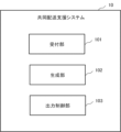
- FIG. 1 is a block diagram showing a configuration example of a joint delivery support system.
- 13 is an explanatory diagram showing an example of a screen for accepting input of arrival time, departure time, and allowable lead time at a base;
- FIG. 13 is an explanatory diagram showing an example of a screen showing candidates being calculated;
- FIG. 13 is an explanatory diagram showing an example of a screen on which candidates for joint delivery conditions are displayed.
- FIG. 13 is an explanatory diagram showing an example of a screen for accepting changes to candidates for joint delivery conditions.
- FIG. 13 is an explanatory diagram showing an example of finalizing a change.
- FIG. 1 is a block diagram showing a configuration example of a joint delivery support system.
- 13 is an explanatory diagram showing an example of a screen for accepting input of arrival time, departure time, and allowable lead time at a base
- FIG. 13 is an explanatory diagram
- FIG. 13 is an explanatory diagram showing an example of a screen indicating that changes cannot be made;
- FIG. 13 is an explanatory diagram showing an example of a screen on which new candidates for joint delivery conditions are displayed.
- 13 is an explanatory diagram showing an example of a screen displaying acceptance of permission for a new candidate;
- FIG. 13 is an explanatory diagram showing an example of a screen displaying a message indicating that permission from another company is being awaited;
- FIG. 13 is an explanatory diagram showing an example of a screen that displays that permission has been granted from all shippers.
- 1 is a flowchart (part 1) showing an operation example of the joint delivery support system.
- 11 is a flowchart (part 2) showing an operation example of the joint delivery support system.
- FIG. 2 is an explanatory diagram illustrating an example of a hardware configuration of a computer.
- joint delivery where multiple shippers load their cargo onto the same delivery vehicle, such as a truck.
- One method of joint delivery is for a shipper to load the cargo of other shippers into the free space of the delivery vehicle they are using.
- Another method of joint delivery is for multiple shippers to prepare a separate delivery vehicle exclusively for joint delivery.
- the joint delivery support system according to the embodiment can be applied to either method.
- the delivery vehicle is not limited to vehicles such as trucks and trains, ships, and airplanes, but the embodiment will be described using trucks as an example.
- FIG. 1 is an explanatory diagram showing an example of a connection between the joint delivery support system and other devices.
- the joint delivery support system 10 is connected to a terminal device 11 via a communication network NT.
- the type of the terminal device 11 is not particularly limited, and may be a PC (Personal Computer), a smartphone, a tablet device, or the like.
- the terminal device 11 may have an application program pre-installed that is capable of transmitting information to the joint delivery support system 10 and outputting information from the joint delivery support system 10.
- terminal device 11 for each shipper there are multiple shippers, so for example, there is a terminal device 11 for each shipper.
- the terminal device 11 for shipper A is represented as terminal device 11-A
- the terminal device 11 for shipper B is represented as terminal device 11-B. Note that when the terminal device is not specified, it is simply represented as terminal device 11.
- FIG. 2 is a block diagram showing an example of the configuration of the joint delivery support system 10.
- the joint delivery support system 10 includes a reception unit 101, a generation unit 102, and an output control unit 103.
- the reception unit 101 receives, for each shipper of a joint delivery, input of base identification information for identifying each base used by the shipper during joint delivery, arrival time, departure time, and allowable lead time for each base.
- the base identification information is not particularly limited to a base code or a base name, as long as it is possible to identify the base.
- the base identification information and the location information of the base may be registered in a database or the like in advance.
- the allowable lead time is an allowable variation time from the input arrival time and departure time.
- the reception unit 101 receives, for each shipper, the load amount of the luggage to be loaded onto the delivery means at each base, and the unload amount of the luggage to be unloaded from the delivery means at the base.
- the load amount and unload amount are used to determine whether joint delivery is established.
- the load amount and unload amount are used to calculate the loading rate of the delivery means during joint delivery.
- the unit of load amount may be, for example, P/L (Pallet), and is not particularly limited.
- FIG. 3 is an explanatory diagram showing an example of a screen that accepts input of the arrival time, departure time, and allowable lead time at the base.
- the output control unit 103 causes each shipper's terminal device 11 to display a screen that accepts input of the name of the base, the arrival time, the departure time, the amount of cargo loaded, the amount of cargo unloaded, and the allowable lead time.
- the screen has input fields into which the maximum load capacity, total load capacity, base name, arrival time, departure time, loaded amount, unloaded amount, and allowable lead time can be input.
- the screen also has a Confirm button. When the Confirm button is pressed, the reception unit 101 accepts the information input into each input field.
- the maximum load capacity is the maximum load capacity that can be loaded onto a truck.
- the total load capacity is the total amount of cargo that the shipper has loaded.
- the generating unit 102 generates candidates for the conditions of the joint delivery, including bases through which the delivery means used in the joint delivery passes, and the arrival time and departure time at the base, based on the received information.
- the generating unit 102 may generate candidates for the conditions of the joint delivery using a learning model.
- the learning model outputs candidates for the conditions of the joint delivery, including the bases through which the delivery means used in the joint delivery passes, and the arrival time and departure time at the base.
- the learning model may be a model capable of outputting a candidate that is the least changed from the arrival time and departure time at the base input by each of the multiple shippers.
- the learning model may be a model capable of outputting a candidate with the lowest delivery fee. Determining the conditions of the joint delivery is also called joint delivery planning. Note that the candidates for the conditions of the joint delivery that are the least changed and the candidate with the lowest delivery fee are merely examples, and are not limited to these.
- the candidate conditions for joint delivery may be the candidate with the lowest delivery fee among the candidates with the least changes from the arrival and departure times at the bases entered by each of the multiple shippers.
- the output control unit 103 may cause each shipper's terminal device 11 to display a screen indicating that the candidates are being generated.
- FIG. 4 is an explanatory diagram showing an example screen showing candidates being calculated.
- the screen of the terminal device 11 displays that candidates for joint delivery conditions are being calculated in joint delivery planning.
- the screen displays that the status of each shipper, both Company A and Company B, are in the process of planning joint delivery plans.
- the output control unit 103 presents the candidates generated by the generation unit 102 to the shipper. Specifically, for example, the output control unit 103 outputs the generated candidates to the shipper's terminal device 11.
- the method of outputting to the shipper's terminal device 11 is not particularly limited to display, audio output, and the like. In the following example, an example of an output method in which the output control unit 103 displays information on the shipper's terminal device 11 will be described.
- the output control unit 103 displays base identification information that identifies bases included in the candidates for joint delivery conditions, and the arrival time and departure time for the base, in a different display format for each shipper who uses the base included in the candidates.
- the display format may be color, pattern, type and size of characters, or a combination of these.
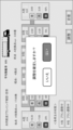
- FIG. 5 is an explanatory diagram showing an example screen on which potential conditions for joint delivery are displayed.
- the screen of the terminal device 11 displays the names of the bases in the order in which they will be passed through during delivery. The screen also displays the arrival and departure times and loading rates for each base, along with the names of the bases.
- the screen displays shipper A's bases and shipper B's bases in different ways. Shipper A's bases are displayed with a dotted pattern, and shipper B's bases are displayed with a striped pattern. Also, in FIG. 5, for each base, the arrival time is represented as "arrival”, the departure time is represented as "departure”, and the loading rate is represented as "load”.
- the screen shows the average loading rate.
- the screen shows the average loading rate using a picture of a truck.
- the joint delivery truck is scheduled to depart from shipper A's base xxx as the starting point at 17:00, pass through three bases, and arrive at shipper A's base xyz as the ending point at 3:00.
- the intermediate points include shipper B's base yyy, shipper B's base yyx, and shipper B's base yxz.
- the reception unit 101 accepts changes to at least one of the arrival time and departure time at the shipper's own base for the presented candidates. Alternatively, the reception unit 101 accepts permission to change at least one of the arrival time and departure time for the presented candidates.
- the screen displays the arrival and departure times at the shipper's own base, which can be amended.
- Shipper A can amend the arrival and departure times at shipper A's base.
- Shipper B can amend the arrival and departure times at shipper B's base.
- the screen of the terminal device 11 has an Adjust button and an Agree button.
- the reception unit 101 accepts a change to at least one of the arrival time and departure time at the shipper's own base.
- the Agree button is pressed, the reception unit 101 accepts permission for at least one of the arrival time and departure time for the presented candidates.
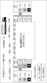
- FIG. 6 is an explanatory diagram showing an example of a screen that accepts changes to candidate conditions for joint delivery.
- FIG. 6 shows an example of the screen for shipper B.
- shipper B modifies the arrival time at base yyy from 6:30 p.m. to 6 p.m.
- the reception unit 101 accepts the change of the arrival time at base yyy from 6:30 p.m. to 6 p.m.
- FIG. 7 is an explanatory diagram showing an example of confirming changes. After the adjustment button is pressed, the changes may be confirmed again. For example, when the adjustment button is pressed, the output control unit 103 causes a screen for confirming the changes to be displayed on the terminal device 11-B of shipper B. In FIG. 7, for example, the screen for confirming the changes is displayed superimposed on the screen shown in FIG. 6.
- the reception unit 101 accepts the change of the arrival time at location yyy from 6:30 p.m. to 6 p.m.
- the output control unit 103 can simply display the screen in FIG. 6 again.
- the reception unit 101 does not accept changes for shippers other than the shipper who is inputting the changes.
- the reception unit 101 may temporarily suspend the acceptance of changes for shippers other than the shipper who is inputting the changes. For example, when changes are being made for shipper B, changes for shipper A will not be accepted.
- FIG. 8 is an explanatory diagram showing an example of a screen indicating that changes cannot be made. Since shipper B is making changes in FIGS. 6 and 7, in FIG. 8 the output control unit 103 causes shipper A's terminal device 11-A to superimpose a screen indicating that another shipper is making changes on the screen shown in FIG. 5.
- the generation unit 102 generates a new candidate for the conditions for joint delivery based on the changes accepted by the acceptance unit 101.
- the new candidate for the conditions for joint delivery is the candidate with the least change in arrival time and departure time from the candidates before regeneration.
- the new candidate for the conditions for joint delivery may be the candidate with the lowest delivery fee.
- the new candidate for the conditions for joint delivery, the candidate with the least change from the candidates before regeneration and the candidate with the lowest delivery fee are merely examples and are not limited to these.
- the candidate for the conditions for joint delivery may be the candidate with the second least change from the candidates before regeneration, or the candidate with the lowest delivery fee among the candidates with the least change from the candidates before regeneration.
- the output control unit 103 presents the new candidates generated by the generation unit 102 to the shipper.
- the presentation method is as described above.
- FIG. 9 is an explanatory diagram showing an example of a screen on which new candidates for joint delivery conditions are displayed.
- the screen configuration of the terminal device 11 in FIG. 9 is the same as the screen configuration of the terminal device 11 in FIG. 5.
- the screen shows that the status of each shipper, as in FIG. 5, is that the joint delivery plan is being adjusted for both Company A and Company B. If the shipper wishes to make another change, the processing of the reception unit 101, generation unit 102, and output control unit 103 described above is repeated.
- the reception unit 101 receives permission for the new candidate. For example, when the agreement button is pressed, the reception unit 101 receives permission for the new candidate.
- the output control unit 103 may cause the terminal device 11 of the shipper who has received permission to display that permission is awaiting from the other shippers.
- the output control unit 103 may cause the shipper's terminal device 11 to display that permission has been received from all shippers.
- the generation unit 102 may not be able to generate a new candidate. That is, there may be no candidate that satisfies the original information input and the changed information. For this reason, if the generation unit 102 cannot generate a new candidate, the output control unit 103 may output that there is no new candidate. More specifically, for example, the output control unit 103 may output "No new candidate for the joint delivery plan could be generated.” If there is no new candidate, some shippers may want to cancel the joint delivery because it does not meet their conditions. Therefore, the screen in FIG. 5 or the screen in FIG.
- the reception unit 101 accepts the cancellation of the joint delivery plan.
- the output control unit 103 notifies the terminal device 11 of each shipper of the cancellation.
- the number of times a shipper can change conditions may be determined in advance. For example, if the reception unit 101 receives changes more than a predetermined number of times, the output control unit 103 may output a message indicating that no further changes can be made.
- the reception unit 101 receives input of base identification information, arrival time, departure time, and lead time allowance for each base, the generation unit 102 generates one candidate for the conditions of joint delivery, and the output control unit 103 presents one candidate to the shipper.
- the generation unit 102 may generate multiple candidates for the conditions of joint delivery based on the received information. Then, the output control unit 103 may present the multiple candidates to the shipper. Then, the reception unit 101 may receive selection of one of the multiple candidates.
- the reception unit 101 may receive permission for the selected candidate from another shipper.
- the reception unit 101 may receive changes to the candidate selected from the multiple candidates. Then, the generation unit 102 may generate a new candidate with the least changes in arrival time and departure time from the selected candidates based on the changes.
- the generating unit 102 generates candidates for the conditions of joint delivery based on the change
- the output control unit 103 presents one candidate to the shipper.
- the generating unit 102 may generate multiple candidates for the conditions of joint delivery based on the accepted change.
- the output control unit 103 presents the multiple candidates.
- the multiple candidates may be, for example, a predetermined number of candidates in order of lowest delivery fee.
- the multiple candidates may include, for example, a candidate with the lowest delivery fee and a candidate with the least change in arrival time and departure time from the candidate before the change.
- the output control unit 103 may display the characteristics of each of the multiple candidates. For example, the output control unit 103 may display the candidate with the lowest fee.
- the receiving unit 101 accepts the selection of any of the multiple candidates.
- the receiving unit 101 may accept permission for the selected candidate from the other shippers.
- (flowchart) 13 and 14 are flow charts showing an example of the operation of the joint delivery support system 10.
- the reception unit 101 receives input of base identification information for identifying bases, arrival time, departure time, unloading amount, loading amount, and allowable lead time for each base (step S101).
- the generation unit 102 generates candidates for joint delivery conditions (step S102).
- the output control unit 103 outputs the candidates for joint delivery conditions (step S103).
- the output control unit 103 causes the terminal device 11 of each shipper to display the candidates for joint delivery conditions.
- the reception unit 101 determines whether a change has been received from any shipper (step S104). If the reception unit 101 has received a change (step S104: Yes), the generation unit 102 generates new candidates for the conditions of joint delivery (step S105). Next, the generation unit 102 determines whether there are new candidates (step S106). If there are new candidates (step S106: Yes), the output control unit 103 outputs the new candidates for the conditions of joint delivery (step S107), and the joint delivery support system 10 returns to step S104. If there are no new candidates (step S106: No), the output control unit 103 outputs a message indicating that there are no candidates (step S108), and the joint delivery support system 10 returns to step S104.
- step S104 determines whether a cancellation of the joint delivery planning has been accepted (step S109). If a cancellation has been accepted (step S109: Yes), the output control unit 103 outputs a notice of cancellation (step S110), and the joint delivery support system 10 exceptionally terminates.
- step S109: No the reception unit 101 determines whether permission has been accepted from all shippers (step S111). If permission has not been accepted from all shippers (step S111: Yes), the joint delivery support system 10 returns to step S104. If permission has been accepted from all shippers (step S111: Yes), the output control unit 103 outputs the joint delivery conditions for candidates that have received permission from all shippers (step S112), and the joint delivery support system 10 ends the process. In step S112, the output control unit 103 may output the joint delivery conditions in a manner that makes it possible to identify that permission has been obtained from all shippers.
- the joint delivery support system 10 when the joint delivery support system 10 accepts a change to the presented candidate joint delivery conditions, it generates a new candidate joint delivery condition based on the accepted change. The joint delivery support system 10 then presents the new candidate to the shipper and accepts approval for the new candidate joint delivery condition. This makes it easy to adjust the arrival and departure times between shippers based on the candidate joint delivery conditions. This makes it easier to create conditions for joint delivery.
- joint delivery support system 10 While the joint delivery support system 10 is accepting changes, it will not accept any changes from shippers other than the shipper who is inputting the changes. This makes it possible to prevent simultaneous changes between multiple shippers.
- the new candidate is the candidate with the least changes in arrival and departure times for each base from the candidates before regeneration. This makes it easier to create conditions for joint deliveries.
- the new candidate is the candidate with the lowest delivery fees. This makes it possible to reduce delivery fees.
- the joint delivery support system 10 also generates multiple candidates for the conditions of joint delivery based on the changes.
- the joint delivery support system 10 then presents the multiple candidates and accepts the selection of one of the multiple candidates. In this way, by presenting various candidates for the changes, it is possible to increase the possibility of other shippers granting approval.
- the joint delivery support system 10 also displays on the shipper's terminal device 11 base identification information that identifies bases included in the candidate conditions for joint delivery, and the arrival and departure times for the bases, in a display format that differs for each shipper who uses bases included in the candidate conditions for joint delivery. This allows the shipper to easily distinguish which shipper each base belongs to. Therefore, the shipper can easily change the arrival and departure times at their own bases.
- the joint delivery support system 10 outputs a message to the shipper who input the changes that there are no new candidates. This allows the shipper to consider making further adjustments.
- the joint delivery support system 10 may be configured to include each functional unit and part of the information.
- the embodiment is not limited to the above-mentioned example, and various modifications are possible.
- the configuration of the joint delivery support system 10 in the embodiment is not particularly limited.
- the joint delivery support system 10 may be realized by a single device, such as a single server.
- the single device may be called a joint delivery support device, an information processing device, or the like, and is not particularly limited.
- the joint delivery support system 10 in the embodiment may be realized by different devices according to function or data.
- each functional unit may be configured by multiple servers and realized as the joint delivery support system 10.
- the joint delivery support system 10 may be realized by a database server including each DB (Database) and a server having each functional unit.
- each piece of information may include a part of the above-mentioned information.
- each piece of information may include information other than the above-mentioned information.
- Each piece of information may be divided into multiple pieces of information in more detail, or may be one DB.
- the process of generating information to be displayed on the terminal device 11 may be performed by the output control unit 103. This process may also be performed by the terminal device 11.
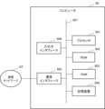
- Fig. 15 is an explanatory diagram showing an example of a hardware configuration of a computer.
- a part or all of each device can be realized by using any combination of a computer 80 and a program as shown in Fig. 15.
- the computer 80 has, for example, a processor 801, a ROM (Read Only Memory) 802, a RAM (Random Access Memory) 803, and a storage device 804.
- the computer 80 also has a communication interface 805 and an input/output interface 806.
- Each component is connected to the other via, for example, a bus 807. Note that the number of each component is not particularly limited, and there may be one or more of each component.
- the processor 801 controls the entire computer 80.
- the processor 801 may be, for example, a CPU (Central Processing Unit), a DSP (Digital Signal Processor), a GPU (Graphics Processing Unit), a PPU (Physics Processing Unit), a TPU (Tensor Processing Unit), a quantum processor, or a combination of these, and is not particularly limited.
- the computer 80 also has a ROM 802, a RAM 803, and a storage device 804 as storage units.
- the storage device 804 include semiconductor memory such as flash memory, a hard disk drive (HDD), and a solid state drive (SSD).
- the storage device 804 stores an OS (operating system) program, application programs, and programs related to the embodiments.
- the ROM 802 stores application programs and programs related to the embodiments.
- the RAM 803 is used as a work area for the processor 801.
- the processor 801 also loads programs stored in the storage device 804, ROM 802, etc. The processor 801 then executes each process coded in the program. The processor 801 may also download various programs via the communications network NT. The processor 801 also functions as a part or all of the computer 80. The processor 801 may then execute the processes or instructions in the illustrated flowchart based on the program.
- the communication interface 805 is connected to a communication network NT, such as a LAN (Local Area Network) or a WAN (Wide Area Network), via a wireless or wired communication line.
- the communication network NT may be composed of multiple communication networks NT.
- the computer 80 is connected to an external device or an external computer 80 via the communication network NT.
- the communication interface 805 serves as an interface between the communication network NT and the inside of the computer 80.
- the communication interface 805 also controls the input and output of data from the external device or the external computer 80.
- each device may be implemented by any combination of a different computer and program for each component.
- multiple components of each device may be implemented by any combination of a single computer and program.
- each device may be realized by circuits for a specific application. Further, some or all of the components of each device may be realized by general-purpose circuits including a processor such as an FPGA (Field Programmable Gate Array). Further, some or all of the components of each device may be realized by a combination of circuits for a specific application and general-purpose circuits. Further, these circuits may be a single integrated circuit. Alternatively, these circuits may be divided into multiple integrated circuits. The multiple integrated circuits may be configured by being connected via a bus or the like.
- each device may be realized by multiple computers, circuits, etc.
- the multiple computers, circuits, etc. may be centralized or distributed.
- the joint delivery support method described in the embodiment is realized by being executed by the joint delivery support system 10.
- the programs described in the embodiments are recorded on a computer-readable recording medium such as a HDD, SSD, flexible disk, optical disk, magneto-optical disk, or USB memory.
- the programs are then executed by a computer by reading them from the recording medium.
- the programs may also be distributed via a communications network NT.
- each component of the joint delivery support system 10 in the embodiment described above may be realized by dedicated hardware, such as a computer.
- each component may be realized by software.
- each component may be realized by a combination of hardware and software.
- (Appendix 1) a receiving means for receiving, for each shipper of a joint delivery, base identification information for identifying each base used by the shipper during the joint delivery, and an input of an arrival time, a departure time, and an allowable lead time for each base; a generating means for generating candidates for conditions of the joint delivery, including the bases through which the delivery means used in the joint delivery passes and arrival times and departure times at the bases, based on the received information; an output control means for outputting the generated candidates; Equipped with The reception means receives a change to at least one of the arrival time and the departure time at the base of the shipper after the presentation, The generating means generates new candidates for the conditions of the joint delivery based on the accepted changes, The output control means outputs the new candidate, The accepting means accepts permission for the new candidate.
- Joint delivery support system (Appendix 2) the reception means, while receiving the change, does not accept changes of other shippers other than the shipper inputting the change; 2.
- the new candidate is a candidate with the least change in the arrival time and the departure time from the candidate before regeneration.
- the new candidate is the candidate with the lowest shipping cost.
- a joint delivery support system according to any one of claims 1 to 3. (Appendix 5)
- the generating means generates a plurality of candidates for the conditions of the joint delivery based on the change,
- the output control means outputs the plurality of candidates,
- the accepting means accepts a selection of any one of the plurality of candidates.
- a joint delivery support system according to any one of claims 1 to 4.
- the output control means displays the base identification information for identifying the bases included in the candidates and the arrival time and the departure time for the bases on the terminal device of the shipper in a display mode that differs for the shipper using the bases included in the candidates.
- a joint delivery support system according to any one of claims 1 to 5.
- the output control means When there is no new candidate based on the accepted change, the output control means outputs a message indicating that there is no new candidate to a terminal device of the shipper who input the change.
- a joint delivery support system according to any one of claims 1 to 6.
- (Appendix 8) accepts input of base identification information for identifying each base used by the shipper in the joint delivery, and an arrival time, a departure time, and an allowable lead time for each base, for each shipper of the joint delivery; Based on the received information, generate candidates for conditions of the joint delivery, including the bases through which the delivery means used in the joint delivery passes and arrival times and departure times at the bases; Outputting the generated candidates; After the submission, the shipper accepts a change to at least one of the arrival time and the departure time at the base; generating new candidates for the conditions of the joint delivery based on the accepted changes; Output the new candidate; Accepting the new candidate's admission; Joint delivery assistance methods.
- (Appendix 9) On the computer, accepts input of base identification information for identifying each base used by the shipper in the joint delivery, and an arrival time, a departure time, and an allowable lead time for each base; Based on the received information, generate candidates for conditions of the joint delivery, including the bases through which the delivery means used in the joint delivery passes and arrival times and departure times at the bases; Outputting the generated candidates; After the submission, the shipper accepts a change to at least one of the arrival time and the departure time at the base; generating new candidates for the conditions of the joint delivery based on the accepted changes; Output the new candidate; Accepting the new candidate's admission; A program that executes a process.
Landscapes
- Business, Economics & Management (AREA)
- Engineering & Computer Science (AREA)
- Economics (AREA)
- Quality & Reliability (AREA)
- Entrepreneurship & Innovation (AREA)
- Human Resources & Organizations (AREA)
- Marketing (AREA)
- Operations Research (AREA)
- Development Economics (AREA)
- Strategic Management (AREA)
- Tourism & Hospitality (AREA)
- Physics & Mathematics (AREA)
- General Business, Economics & Management (AREA)
- General Physics & Mathematics (AREA)
- Theoretical Computer Science (AREA)
- Management, Administration, Business Operations System, And Electronic Commerce (AREA)
Abstract
Description
図13および図14は、共同配送支援システム10の一動作例を示すフローチャートである。受付部101は、拠点を識別する拠点識別情報、各拠点別に到着時刻、出発時刻、降し荷量、積み荷量、リードタイム許容時間の入力を受け付ける(ステップS101)。生成部102は、共同配送の条件の候補を生成する(ステップS102)。出力制御部103は、共同配送の条件の候補を出力する(ステップS103)。ステップS103において出力制御部103は、各荷主の端末装置11に、共同配送の条件の候補を表示させる。
つぎに、実施の形態において説明した共同配送支援システム10、端末装置11などの各装置をコンピュータで実現した場合のハードウェア構成例について説明する。図15は、コンピュータのハードウェア構成例を示す説明図である。例えば、各装置の一部または全部は、図15に示すようなコンピュータ80とプログラムとの任意の組み合わせを用いて実現することも可能である。
共同配送の荷主別に、前記荷主が前記共同配送時に利用する各拠点を識別する拠点識別情報、前記拠点別に前記拠点の到着時刻、出発時刻、およびリードタイム許容時間の入力を受け付ける受付手段と、
受け付けた情報に基づいて、前記共同配送で用いる配送手段が経由する前記拠点と、前記拠点における到着時刻および出発時刻と、を含む前記共同配送の条件の候補を生成する生成手段と、
生成された前記候補を出力する出力制御手段と、
を備え、
前記受付手段は、提示後に、前記荷主自身の前記拠点における到着時刻および出発時刻の少なくともいずれかの変更を受け付け、
前記生成手段は、受け付けた前記変更に基づいて、前記共同配送の条件の新たな候補を生成し、
前記出力制御手段は、新たな前記候補を出力し、
前記受付手段は、新たな前記候補の許可を受け付ける、
共同配送支援システム。
(付記2)
前記受付手段は、前記変更を受け付け中に、前記変更を入力している荷主以外の他の荷主の変更を受け付けない、
付記1に記載の共同配送支援システム。
(付記3)
新たな前記候補は、再生成前の前記候補から、前記到着時刻および前記出発時刻に最も変更がない候補である、
付記1または付記2に記載の共同配送支援システム。
(付記4)
新たな前記候補は、最も配送料金が低い候補である、
付記1から付記3のいずれかに記載の共同配送支援システム。
(付記5)
前記生成手段は、前記変更に基づいて、前記共同配送の条件の複数通りの候補を生成し、
前記出力制御手段は、前記複数通りの候補を出力し、
前記受付手段は、前記複数通りの候補からいずれかの候補の選択を受け付ける、
付記1から付記4のいずれかに記載の共同配送支援システム。
(付記6)
前記出力制御手段は、前記候補に含まれる前記拠点を識別する前記拠点識別情報および前記拠点についての前記到着時刻および前記出発時刻を、前記候補に含まれる前記拠点を利用する前記荷主で異なる表示態様で前記荷主の端末装置に表示させる、
付記1から付記5のいずれかに記載の共同配送支援システム。
(付記7)
前記出力制御手段は、受け付けた前記変更に基づく新たな前記候補がない場合、前記変更を入力した荷主の端末装置に新たな前記候補がないことを出力する、
付記1から付記6のいずれかに記載の共同配送支援システム。
(付記8)
共同配送の荷主別に、前記荷主が前記共同配送時に利用する各拠点を識別する拠点識別情報、前記拠点別に到着時刻、出発時刻、およびリードタイム許容時間の入力を受け付け、
受け付けた情報に基づいて、前記共同配送で用いる配送手段が経由する前記拠点と、前記拠点における到着時刻および出発時刻と、を含む前記共同配送の条件の候補を生成し、
生成された前記候補を出力し、
提示後に、前記荷主自身の前記拠点における到着時刻および出発時刻の少なくともいずれかの変更を受け付け、
受け付けた前記変更に基づいて、前記共同配送の条件の新たな候補を生成し、
新たな前記候補を出力し、
新たな前記候補の許可を受け付ける、
共同配送支援方法。
(付記9)
コンピュータに、
共同配送の荷主別に、前記荷主が前記共同配送時に利用する各拠点を識別する拠点識別情報、前記拠点別に前記拠点の到着時刻、出発時刻、およびリードタイム許容時間の入力を受け付け、
受け付けた情報に基づいて、前記共同配送で用いる配送手段が経由する前記拠点と、前記拠点における到着時刻および出発時刻と、を含む前記共同配送の条件の候補を生成し、
生成された前記候補を出力し、
提示後に、前記荷主自身の前記拠点における到着時刻および出発時刻の少なくともいずれかの変更を受け付け、
受け付けた前記変更に基づいて、前記共同配送の条件の新たな候補を生成し、
新たな前記候補を出力し、
新たな前記候補の許可を受け付ける、
処理を実行させるプログラム。
(付記10)
コンピュータに、
共同配送の荷主別に、前記荷主が前記共同配送時に利用する各拠点を識別する拠点識別情報、前記拠点別に前記拠点の到着時刻、出発時刻、およびリードタイム許容時間の入力を受け付け、
受け付けた情報に基づいて、前記共同配送で用いる配送手段が経由する前記拠点と、前記拠点における到着時刻および出発時刻と、を含む前記共同配送の条件の候補を生成し、
生成された前記候補を出力し、
提示後に、前記荷主自身の前記拠点における到着時刻および出発時刻の少なくともいずれかの変更を受け付け、
受け付けた前記変更に基づいて、前記共同配送の条件の新たな候補を生成し、
新たな前記候補を出力し、
新たな前記候補の許可を受け付ける、
処理を実行させるプログラムを記録する、前記コンピュータが読み取り可能な非一時的な記録媒体。
11,11-A,11-B 端末装置
80 コンピュータ
101 受付部
102 生成部
103 出力制御部
801 プロセッサ
802 ROM
803 RAM
804 記憶装置
805 通信インタフェース
806 入出力インタフェース
807 バス
NT 通信ネットワーク
Claims (20)
- 共同配送の荷主別に、前記荷主が前記共同配送時に利用する各拠点を識別する拠点識別情報、前記拠点別に前記拠点の到着時刻、出発時刻、およびリードタイム許容時間の入力を受け付ける受付手段と、
受け付けた情報に基づいて、前記共同配送で用いる配送手段が経由する前記拠点と、前記拠点における到着時刻および出発時刻と、を含む前記共同配送の条件の候補を生成する生成手段と、
生成された前記候補を出力する出力制御手段と、
を備え、
前記受付手段は、出力後に、前記荷主自身の前記拠点における到着時刻および出発時刻の少なくともいずれかの変更を受け付け、
前記生成手段は、受け付けた前記変更に基づいて、前記共同配送の条件の新たな候補を生成し、
前記出力制御手段は、新たな前記候補を出力し、
前記受付手段は、新たな前記候補の許可を受け付ける、
共同配送支援システム。 - 前記受付手段は、前記変更を受け付け中に、前記変更を入力している荷主以外の他の荷主の変更を受け付けない、
請求項1に記載の共同配送支援システム。 - 新たな前記候補は、再生成前の前記候補から、前記到着時刻および前記出発時刻に最も変更がない候補である、
請求項1または請求項2に記載の共同配送支援システム。 - 新たな前記候補は、最も配送料金が低い候補である、
請求項1から請求項3のいずれかに記載の共同配送支援システム。 - 前記生成手段は、前記変更に基づいて、前記共同配送の条件の複数通りの候補を生成し、
前記出力制御手段は、前記複数通りの候補を出力し、
前記受付手段は、前記複数通りの候補からいずれかの候補の選択を受け付ける、
請求項1から請求項4のいずれかに記載の共同配送支援システム。 - 前記出力制御手段は、前記候補に含まれる前記拠点を識別する前記拠点識別情報および前記拠点についての前記到着時刻および前記出発時刻を、前記候補に含まれる前記拠点を利用する前記荷主で異なる表示態様で前記荷主の端末装置に表示させる、
請求項1から請求項5のいずれかに記載の共同配送支援システム。 - 前記出力制御手段は、受け付けた前記変更に基づく新たな前記候補がない場合、前記変更を入力した荷主の端末装置に新たな前記候補がないことを出力する、
請求項1から請求項6のいずれかに記載の共同配送支援システム。 - 共同配送の荷主別に、前記荷主が前記共同配送時に利用する各拠点を識別する拠点識別情報、前記拠点別に前記拠点の到着時刻、出発時刻、およびリードタイム許容時間の入力を受け付け、
受け付けた情報に基づいて、前記共同配送で用いる配送手段が経由する前記拠点と、前記拠点における到着時刻および出発時刻と、を含む前記共同配送の条件の候補を生成し、
生成された前記候補を出力し、
出力後に、前記荷主自身の前記拠点における到着時刻および出発時刻の少なくともいずれかの変更を受け付け、
受け付けた前記変更に基づいて、前記共同配送の条件の新たな候補を生成し、
新たな前記候補を出力し、
新たな前記候補の許可を受け付ける、
共同配送支援方法。 - 前記受け付けにおいて、前記変更を受け付け中に、前記変更を入力している荷主以外の他の荷主の変更を受け付けない、
請求項8に記載の共同配送支援方法。 - 新たな前記候補は、再生成前の前記候補から、前記到着時刻および前記出発時刻に最も変更がない候補である、
請求項8または請求項9に記載の共同配送支援方法。 - 新たな前記候補は、最も配送料金が低い候補である、
請求項8から請求項10のいずれかに記載の共同配送支援方法。 - 前記生成において、前記変更に基づいて、前記共同配送の条件の複数通りの候補を生成し、
前記出力において、前記複数通りの候補を出力し、
前記受け付けにおいて、前記複数通りの候補からいずれかの候補の選択を受け付ける、
請求項8から請求項11のいずれかに記載の共同配送支援方法。 - 前記出力において、前記候補に含まれる前記拠点を識別する前記拠点識別情報および前記拠点についての前記到着時刻および前記出発時刻を、前記候補に含まれる前記拠点を利用する前記荷主で異なる表示態様で前記荷主の端末装置に表示させる、
請求項8から請求項12のいずれかに記載の共同配送支援方法。 - 前記出力において、受け付けた前記変更に基づく新たな前記候補がない場合、前記変更を入力した荷主の端末装置に新たな前記候補がないことを出力する、
請求項8から請求項13のいずれかに記載の共同配送支援方法。 - コンピュータに、
共同配送の荷主別に、前記荷主が前記共同配送時に利用する各拠点を識別する拠点識別情報、前記拠点別に前記拠点の到着時刻、出発時刻、およびリードタイム許容時間の入力を受け付け、
受け付けた情報に基づいて、前記共同配送で用いる配送手段が経由する前記拠点と、前記拠点における到着時刻および出発時刻と、を含む前記共同配送の条件の候補を生成し、
生成された前記候補を出力し、
出力後に、前記荷主自身の前記拠点における到着時刻および出発時刻の少なくともいずれかの変更を受け付け、
受け付けた前記変更に基づいて、前記共同配送の条件の新たな候補を生成し、
新たな前記候補を出力し、
新たな前記候補の許可を受け付ける、
処理を実行させるプログラムを記録する、前記コンピュータが読み取り可能な非一時的な記録媒体。 - 前記受け付けにおいて、前記変更を受け付け中に、前記変更を入力している荷主以外の他の荷主の変更を受け付けない、
請求項15に記載の記録媒体。 - 新たな前記候補は、再生成前の前記候補から、前記到着時刻および前記出発時刻に最も変更がない候補である、
請求項15または請求項16に記載の記録媒体。 - 新たな前記候補は、最も配送料金が低い候補である、
請求項15から請求項17のいずれかに記載の記録媒体。 - 前記生成において、前記変更に基づいて、前記共同配送の条件の複数通りの候補を生成し、
前記出力において、前記複数通りの候補を出力し、
前記受け付けにおいて、前記複数通りの候補からいずれかの候補の選択を受け付ける、
請求項15から請求項18のいずれかに記載の記録媒体。 - 前記出力において、前記候補に含まれる前記拠点を識別する前記拠点識別情報および前記拠点についての前記到着時刻および前記出発時刻を、前記候補に含まれる前記拠点を利用する前記荷主で異なる表示態様で前記荷主の端末装置に表示させる、
請求項15から請求項19のいずれかに記載の記録媒体。
Priority Applications (1)
| Application Number | Priority Date | Filing Date | Title |
|---|---|---|---|
| JP2025506504A JPWO2024190052A5 (ja) | 2024-01-11 | 共同配送支援システム、共同配送支援方法、およびプログラム |
Applications Claiming Priority (2)
| Application Number | Priority Date | Filing Date | Title |
|---|---|---|---|
| JP2023037878 | 2023-03-10 | ||
| JP2023-037878 | 2023-03-10 |
Publications (1)
| Publication Number | Publication Date |
|---|---|
| WO2024190052A1 true WO2024190052A1 (ja) | 2024-09-19 |
Family
ID=92754774
Family Applications (1)
| Application Number | Title | Priority Date | Filing Date |
|---|---|---|---|
| PCT/JP2024/000380 Ceased WO2024190052A1 (ja) | 2023-03-10 | 2024-01-11 | 共同配送支援システム、共同配送支援方法、および記録媒体 |
Country Status (1)
| Country | Link |
|---|---|
| WO (1) | WO2024190052A1 (ja) |
Citations (2)
| Publication number | Priority date | Publication date | Assignee | Title |
|---|---|---|---|---|
| JP2005075634A (ja) * | 2003-09-03 | 2005-03-24 | Nippon Express Co Ltd | 共同配送情報管理システム |
| WO2021038671A1 (ja) * | 2019-08-23 | 2021-03-04 | 株式会社日立物流 | 出荷計画決定支援システム、コンピュータ、端末、出荷計画決定支援方法及びプログラム |
-
2024
- 2024-01-11 WO PCT/JP2024/000380 patent/WO2024190052A1/ja not_active Ceased
Patent Citations (2)
| Publication number | Priority date | Publication date | Assignee | Title |
|---|---|---|---|---|
| JP2005075634A (ja) * | 2003-09-03 | 2005-03-24 | Nippon Express Co Ltd | 共同配送情報管理システム |
| WO2021038671A1 (ja) * | 2019-08-23 | 2021-03-04 | 株式会社日立物流 | 出荷計画決定支援システム、コンピュータ、端末、出荷計画決定支援方法及びプログラム |
Also Published As
| Publication number | Publication date |
|---|---|
| JPWO2024190052A1 (ja) | 2024-09-19 |
Similar Documents
| Publication | Publication Date | Title |
|---|---|---|
| TWI897426B (zh) | 用於商品銷售服務中提供購物車頁面之方法及電子裝置 | |
| US10268982B2 (en) | Carrier and shipper interfacing and shipment tracking framework for efficient scheduling and transportation of cargo, with security monitoring and efficient payment to carriers | |
| US20240160493A1 (en) | Dynamic modeler | |
| KR20230036951A (ko) | 상품 정보를 제공하는 방법 및 장치 | |
| JP2021089734A (ja) | 商品を予約購入する方法およびシステム | |
| WO2024190052A1 (ja) | 共同配送支援システム、共同配送支援方法、および記録媒体 | |
| US20230342803A9 (en) | System and method of providing a rewards-based, universal, integrated code base | |
| KR101854632B1 (ko) | 배달 상황 정보에 기반하여 조리 정보를 제공하는 방법 및 그 판매 관리 장치 | |
| CN113196330A (zh) | 电子装置及其操作方法 | |
| JP7605778B2 (ja) | 発注処理装置、発注処理方法、及び発注処理プログラム | |
| CN112308652A (zh) | 服务器、信息处理系统以及信息处理方法 | |
| WO2024184989A1 (ja) | 共同配送支援システム、共同配送支援方法、および記録媒体 | |
| JP7769997B1 (ja) | 情報処理装置、情報処理方法、およびプログラム | |
| KR20220081563A (ko) | 에이에스 중개 서비스 시스템 및 그 서비스 제공 방법 | |
| US20230169411A1 (en) | Information processing device, information processing system, and information processing method | |
| US20190303182A1 (en) | System and method for providing advice and assistance through task-tracking systems | |
| US12560442B2 (en) | Smart transaction system with IoT integration for purchase requests | |
| US20250190927A1 (en) | Method and terminal device | |
| CN118536784B (zh) | 计算采购件净需求的方法、装置、设备及存储介质 | |
| JP7743918B2 (ja) | 配送支援システム、配送支援方法、およびプログラム | |
| TWI909335B (zh) | 服務型廠商的自動盤查與自主揭露系統 | |
| JP7424660B2 (ja) | 情報処理システム、情報処理装置、情報処理方法及びプログラム | |
| JP2020191049A (ja) | コンテンツ配信方法、コンテンツ配信装置、及びコンテンツ配信プログラム | |
| US20260111979A1 (en) | Negotiation device, negotiation method, and recording medium | |
| KR20200107724A (ko) | 뱃지 시스템을 이용한 플랫폼 사용자 관리 방법 |
Legal Events
| Date | Code | Title | Description |
|---|---|---|---|
| 121 | Ep: the epo has been informed by wipo that ep was designated in this application |
Ref document number: 24770174 Country of ref document: EP Kind code of ref document: A1 |
|
| ENP | Entry into the national phase |
Ref document number: 2025506504 Country of ref document: JP Kind code of ref document: A |
|
| WWE | Wipo information: entry into national phase |
Ref document number: 2025506504 Country of ref document: JP |
|
| NENP | Non-entry into the national phase |
Ref country code: DE |
|
| 122 | Ep: pct application non-entry in european phase |
Ref document number: 24770174 Country of ref document: EP Kind code of ref document: A1 |