WO2024189793A1 - Scadaウェブhmiシステム - Google Patents
Scadaウェブhmiシステム Download PDFInfo
- Publication number
- WO2024189793A1 WO2024189793A1 PCT/JP2023/009923 JP2023009923W WO2024189793A1 WO 2024189793 A1 WO2024189793 A1 WO 2024189793A1 JP 2023009923 W JP2023009923 W JP 2023009923W WO 2024189793 A1 WO2024189793 A1 WO 2024189793A1
- Authority
- WO
- WIPO (PCT)
- Prior art keywords
- scada
- hmi
- client
- web
- machine
- Prior art date
- Legal status (The legal status is an assumption and is not a legal conclusion. Google has not performed a legal analysis and makes no representation as to the accuracy of the status listed.)
- Ceased
Links
Images




Classifications
-
- G—PHYSICS
- G05—CONTROLLING; REGULATING
- G05B—CONTROL OR REGULATING SYSTEMS IN GENERAL; FUNCTIONAL ELEMENTS OF SUCH SYSTEMS; MONITORING OR TESTING ARRANGEMENTS FOR SUCH SYSTEMS OR ELEMENTS
- G05B19/00—Program-control systems
- G05B19/02—Program-control systems electric
- G05B19/04—Program control other than numerical control, i.e. in sequence controllers or logic controllers
- G05B19/05—Programmable logic controllers, e.g. simulating logic interconnections of signals according to ladder diagrams or function charts
- G05B19/052—Linking several PLC's
-
- G—PHYSICS
- G05—CONTROLLING; REGULATING
- G05B—CONTROL OR REGULATING SYSTEMS IN GENERAL; FUNCTIONAL ELEMENTS OF SUCH SYSTEMS; MONITORING OR TESTING ARRANGEMENTS FOR SUCH SYSTEMS OR ELEMENTS
- G05B19/00—Program-control systems
- G05B19/02—Program-control systems electric
- G05B19/04—Program control other than numerical control, i.e. in sequence controllers or logic controllers
- G05B19/05—Programmable logic controllers, e.g. simulating logic interconnections of signals according to ladder diagrams or function charts
-
- G—PHYSICS
- G05—CONTROLLING; REGULATING
- G05B—CONTROL OR REGULATING SYSTEMS IN GENERAL; FUNCTIONAL ELEMENTS OF SUCH SYSTEMS; MONITORING OR TESTING ARRANGEMENTS FOR SUCH SYSTEMS OR ELEMENTS
- G05B2219/00—Program-control systems
- G05B2219/10—Plc systems
- G05B2219/13—Plc programming
- G05B2219/13144—GUI graphical user interface, icon, function bloc editor, OI operator interface
Definitions
- the present invention relates to a SCADA web HMI system, and in particular to a technology for reducing the processing load in a large-scale system.
- SCADA Supervisory Control and Data Acquisition
- Social infrastructure systems include steel rolling systems, power transmission and transformation systems, water and sewerage treatment systems, building management systems, and road systems.
- SCADA is a type of industrial control system that uses computers to monitor systems, control processes, and collect data. SCADA requires responsiveness (real-time performance) that matches the processing performance of the system.
- SCADA generally consists of the following subsystems: (1) HMI (Human Machine Interface) An HMI is a mechanism that presents data of monitored devices to an operator, enabling the operator to monitor and control the monitored devices. (2) Monitoring and Control System The monitoring and control system is configured by a programmable logic controller (PLC) etc. The monitoring and control system collects data of the monitored devices and sends control commands to the monitored devices. (3) Remote Input Output (RIO) The remote input/output device is connected to a sensor installed in the monitored device, converts the sensor signal into digital data, and sends the digital data to the monitoring and control system. (4) Communications infrastructure The communications infrastructure connects the monitoring and control system to remote input/output devices.
- PLC programmable logic controller
- Patent Document 1 discloses a system that includes an HMI client machine and a SCADA server machine.
- the SCADA server machine transmits data (input/output signals, alarm signals) received from the PLC to the HMI client machine.
- the input/output signals are signals related to the monitored device (the group of field devices that make up the industrial plant), and include actuator control signals and sensor detection signals.
- the HMI subsystem may link a large number of signals, over 200,000 points, to the PLC.
- Conventional SCADA server machines which handle both supervisory control and data collection, require high-performance processors and large-capacity memory to process a large number of signals in real time. For this reason, there is a demand for low-cost realization of HMI subsystems that can be applied to large-scale systems.
- the inventors of the present application have developed a browser-based SCADA HMI subsystem. This makes it possible to realize an HMI screen as a web application that runs on a web browser.
- data for the history screen can be obtained from an online data collector (ODG: Online Data Gathering) that collects and stores all PLC data, while data for the monitoring screen, which requires real-time performance, can be obtained from the SCADA server.
- ODG Online Data Gathering
- the SCADA server can specialize in real-time monitoring functions. In order to process a large number of signals with a low-cost SCADA server, it is desirable to reduce the processing load of input/output signals (including actuator control signals and sensor detection signals) and alarm signals.
- a large-scale SCADA web HMI system it is assumed that a large number of client machines (for example, 128 machines) will be connected to one SCADA server machine. Even in a redundant design in which two SCADA servers are provided to distribute the load, a large number of HMI client machines are connected to each SCADA server machine.
- the SCADA server machine needs to receive the signal data contained in the HMI screen and send it to all HMI client machines.
- the HMI screen on the HMI client machine is displayed by a web browser, and signal data is sent from the SCADA server machine to the HMI client machine using, for example, a point-to-point connection such as WebSocket.
- multicast transmission cannot be used to send data from the SCADA server machine to the HMI client machine. Therefore, if 128 client machines are connected to a SCADA server machine, the SCADA server machine must send 128 times the amount of signal data it receives to the HMI client machine. In this way, when the system is in operation (when the industrial plant is being monitored), a large amount of data flows between the SCADA server machine and each HMI client machine.
- a program that runs on a web browser is downloaded from a SCADA server and executed.
- the web browser on each HMI client machine needs a SCADA web program, and this SCADA web program is loaded from the SCADA server machine via a WebSocket.
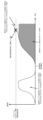
- FIG. 12 if a web browser is started on each HMI client machine before the system starts operating, even if the SCADA web program is loaded via a WebSocket to the web browsers of all HMI client machines, the amount of communication between the HMI client machine and the SCADA server machine is below the communication capacity limit (communication capacity), and there is no problem in system operation.
- the present invention has been made to solve the problems described above, and aims to provide a SCADA web HMI system that can prevent the amount of communication between an HMI client machine and a SCADA server machine from exceeding the communication capacity, even when a web browser is launched during system operation.
- the first aspect of the present disclosure relates to a SCADA web HMI system.
- the SCADA web HMI system includes a programmable logic controller (hereinafter, PLC), an HMI client machine, and a SCADA server machine, which are connected via a computer network.
- PLC programmable logic controller
- the PLC transmits block data related to a group of field devices that constitute an industrial plant to the SCADA server machine at a predetermined interval.
- the SCADA server machine includes a communication driver that receives the block data, and a client management unit that is connected one-to-one to a plurality of the HMI client machines and communicates with each HMI client machine via WebSocket.
- the HMI client machines each execute a web browser that displays an HMI screen on which parts indicating the status of the industrial plant are arranged, and monitor the industrial plant by updating the status of the parts according to the signal data received from the client management unit.
- the HMI client machine includes a client installer that installs the loaded SCADA web program when the web browser is started.
- the second aspect has the following features in addition to those of the first aspect.
- the SCADA server machine is provided with a client installer that is the same as the client installer. Prior to monitoring the industrial plant, the client installer is downloaded from the SCADA server machine to the HMI client machine via the client management unit using the web browser.
- the third aspect has the following features in addition to the first or second aspect.
- the SCADA server machine includes a communication module including content that runs on the SCADA web program.
- the HMI client machine loads the communication module from the SCADA server machine.
- the web browser exchanges data between the SCADA web program running on the domain of the HMI client machine and the communication module running on the domain of the SCADA server machine using inter-domain communication.
- the fourth aspect has the following features in addition to the first or second aspect.
- the SCADA server machine downloads application-dependent data, which is data that depends on an application that runs on the SCADA web program, and transmits the downloaded application-dependent data to the HMI client machine.
- application-dependent data is data that depends on an application that runs on the SCADA web program
- the SCADA server machine determines whether the SCADA web program has been updated, and transmits the application-dependent data to the HMI client machine only if the SCADA web program has been updated.
- the fifth aspect has the following features in addition to the fourth aspect.
- the HMI client machine transmits the revision of the application-dependent data contained in the SCADA web program to the SCADA server machine.
- the SCADA server machine compares the revision received from the HMI client machine with the revision of the application-dependent data downloaded to perform the determination.
- a client installer is provided in the HMI client machine, so that when the web browser is started, the SCADA web program is not loaded from the SCADA server machine via a WebSocket, but is loaded from the HMI client machine itself. Therefore, even if the web browser is started during system operation, it is possible to prevent the amount of communication between the HMI client machine and the SCADA server machine from exceeding the communication capacity.
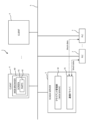
- FIG. 1 is a diagram for explaining a configuration example of a SCADA web HMI system according to an embodiment of the present invention
- FIG. 4A is a diagram for explaining the data type of signal data
- FIG. 4B is a diagram for explaining an identifier.
- FIG. 4A is a diagram for explaining a format of signal data
- FIG. 4B is a diagram for explaining a format of screen update data.
- FIG. 2 is a diagram for explaining processing in a client management unit of the SCADA server machine.
- FIG. 2 is a diagram for explaining a method for loading a SCADA web program.
- FIG. 13 is a diagram for explaining advance distribution of a client installer to an HMI client machine.
- FIG. 2 is a diagram for explaining a method for loading a communication module.
- FIG. 13 is a diagram for explaining another method of loading a communication module.
- FIG. 13 is a diagram for explaining a method of loading application-dependent data.
- 11 is a flowchart illustrating a method for loading application-dependent data.
- FIG. 2 is a block diagram showing an example of the hardware configuration of a SCADA server machine and an HMI client machine.
- FIG. 1 is a diagram for explaining a problem in the related art.
- SCADA Web HMI System Fig. 1 is a diagram for explaining a configuration example of a SCADA Web HMI system according to the first embodiment.
- the SCADA Web HMI system 1 shown in Fig. 1 includes a PLC 2, a SCADA server machine 3, and an HMI client machine 4, which are mutually connected via a computer network 5.
- the computer network 5 is, for example, Ethernet (registered trademark).
- the SCADA Web HMI system 1 may include an online data gathering machine (ODG: Online Data Gathering) (not shown).
- ODG Online Data Gathering
- the PLC 2 is connected to a group of field devices (including actuators and sensors) that make up the industrial plant via a control network (not shown).
- the PLC 2 transmits packets including block data to the computer network 5 by multicast or broadcast at predetermined intervals.
- Block data is a collection of PLC signals.
- One block of data includes tens to hundreds of PLC signals.
- Types of PLC signals include input/output signals (including actuator control signals and sensor detection signals) and alarm signals.
- Block data includes at least one of a collection of input/output signals and a collection of alarm signals. The total number of alarm signals is smaller than the total number of input/output signals.
- Block data is transmitted periodically regardless of whether the value of the PLC signal has changed from the previous value. Therefore, even if a packet containing transmitted block data is lost, it is retransmitted in the next transmission cycle, and the latest status is reflected in the SCADA server machine 3 and the online data collector.
- the SCADA server machine 3 includes a communication driver 31 and a client management unit 32.
- the communication driver 31 is configured to receive block data from the PLC 2 at regular intervals and execute unpacking to break down the received block data into signal data of each data type. In addition to the bit type shown in FIG. 2(a), short type, float type, etc. can be used as the data type. Furthermore, the communication driver 31 is configured to execute packet processing to generate packets for each data type by adding a signal data identifier (see FIG. 2(b)) corresponding to each signal data and transmit the generated packets to the client management unit 32. That is, the signal data transmitted from the communication driver 31 to the client management unit 32 is a pair of a signal data identifier and a signal data value (see FIG. 3(a)).
- the signal data identifier corresponds to a character string written by the application designer.
- the data size of the signal data identifier is, for example, 23 bits. This allows the signal data identifier to represent approximately 8 million pieces of signal data, which is sufficient for a large-scale SCADA web HMI system 1.
- the signal data identifier is 23 bits and the data value is 4 bytes, so 1 bit of padding is added and the data size per signal is 7 bytes. Note that when generating a packet, only the signal data of the signal data identifier related to the HMI screen 41 currently displayed on the web browser 40 may be extracted.
- the client management unit 32 has a signal data reception thread, at least one signal data buffer, and a signal data transmission thread.
- the signal data reception thread receives packets (signal data for each data type) from the communication driver 31 and stores the signal data in the signal data buffer.
- the signal data buffer has an area (array) for storing signal data for each data type. Even if 8 million pieces of signal data exist, the memory usage is about 24 Mbytes, excluding text type, so it can be said that this is not a problem considering the specifications of current computers. In addition, by using an index, the amount of data stored in the signal data buffer can be reduced.
- the signal data transmission thread When the signal data transmission thread receives an instruction from the signal data reception thread, it reads out the signal data stored in the signal data buffer and transmits the read signal data to the HMI client machine 4 for each data type. At this time, the screen identifier and product identifier indicating the HMI screen 41 and product (part) 42 displayed in FIG. 3(b) and the updated signal data are transmitted to the HMI client machine 4 as screen update data (see FIG. 4). As shown in Figures 2 to 4, by converting the signal data into binary data, the amount of data sent to the HMI client machine 4 can be reduced.
- the SCADA server machine 3 includes a processor 301 that executes various processes, a memory 302 in which various information is stored, and a network interface 303.
- the processor 301 executes programs stored in the memory 302, thereby performing the various processes described above and below.
- the HMI client machine 4 includes a processor 401, a memory 402, a monitor 403, a network interface 404, and an input interface 405, all of which are shown in FIG. 11 and described below.
- the processor 401 is configured to execute a program stored in the memory 402, thereby executing a web browser 40 that displays an HMI screen 41 on which display parts are arranged.
- the monitor 403 displays the web browser 40.
- the web browser 40 can switch the connection destination (SCADA server machine 3, online data collector 4) according to the URL, and obtain various information of HTML documents related to the HMI screen 41 from the web server specified by the URL.
- the HMI screen 41 includes a monitoring screen that requires real-time performance, and a history screen that displays historical data.
- the web browser 40 changes the display state of the display parts 42 in response to input/output signals received from the SCADA server machine 3. Changes in the display state include, for example, changes in numbers, characters, colors, and shapes.
- the web browser 40 also changes the display state of the alarm parts 42 arranged on the HMI screen 41 in response to alarm signals received from the SCADA server machine 3.
- the web browser 40 requests history data from the online data collector.
- the web browser 40 displays the history data received from the online data collector on the history screen.
- the online data collector includes a processor and memory, not shown.
- the processor is configured to execute a program stored in the memory, thereby executing Web server processing and history data management processing.
- the online data collector periodically receives block data from the PLC 2.
- the history data management processing of the online data collector accumulates history data of all signals included in the received block data in memory (including a database).
- the Web server processing of the online data collector transmits history data in response to a request from the Web browser 40.
- the online data collector also receives and accumulates alarm packets from the SCADA server machine 3.
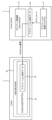
- FIG. 5 is a diagram for explaining a method for loading a SCADA web program.
- the HMI client machine 4 includes a client installer 43.
- the client installer 43 operates when the SCADA web program is updated, and deploys a local web server 45 and a SCADA web program 44 in the client machine 4.
- the web browser 40 can load the SCADA web program via the local web server 45 at startup. This allows the communication bandwidth between the HMI client machine 4 and the SCADA server machine 3 to be fully allocated to communication traffic during system operation, unlike the conventional case in which the SCADA web program 44 is loaded from the SCADA server machine 3.
- the client installer 43 may be installed on the HMI client machine 4 using a CD-ROM, but as shown in FIG. 6, if the client installer 43 is pre-distributed (HTTP loaded) from the SCADA server machine 3 to the HMI client machine 4, the time and effort required for installing the client installer 43 can be reduced, thereby reducing operational costs. That is, the SCADA server machine 3 is provided with the client installer 43.
- This client installer 43 includes a local web server 45 that runs on the client machine 4, a SCADA web program 44, and a SCADA web program startup script 46. This allows the system operation administrator to download the client installer 43 from the SCADA server machine 3 using only the web browser 40.
- the client installer 43 is executed on the HMI client machine 4
- the local web server 45 starts on the HMI client machine 4
- the SCADA web program 44 and the SCADA web program startup script 46 are placed on the client machine 4.
- a shortcut linked to the SCADA web program startup script 46 is placed on the Windows (registered trademark) desktop of the monitor 403, so the operator can simply double-click the shortcut to load the SCADA web program 44 on the web browser 40.
- the SCADA web program startup script 46 also contains the communication address of the SCADA server machine 3, so the SCADA web program 44 automatically connects to the SCADA server machine 3, and the operator can immediately start monitoring the system.
- FIG. 7 is a diagram for explaining a communication module loading method
- Fig. 8 is a diagram for explaining another communication module loading method.
- the communications module 36 provides the functionality required for the SCADA web program 44 to communicate with the server. This type of communications module 36 needs to be loaded from the SCADA server machine 3, not from the local web server 45.
- the SCADA server machine 3 is equipped with a server installer 34. When the server installer 34 is started, the server program 35 and communications module 36 are placed on the SCADA server machine 3.
- the communications module 36 needs to perform WebSocket communication with the client management unit 32 on the SCADA server machine 3, but for security reasons known as the same-origin policy, it must operate in the domain 40b of the SCADA server machine 3. In other words, the communications module 36 needs to be loaded from the client management unit 32 on the SCADA server machine 3. Therefore, as shown in FIG.
- Fig. 9 is a diagram for explaining the application-dependent data loading method
- Fig. 10 is a flowchart for explaining the application-dependent data loading method.
- the application-dependent data 38 that depends on the application must also be loaded on the web browser 40.
- the application-dependent data 38 is downloaded to the SCADA server machine 3 by the application distribution program 37.
- the application-dependent data 38 includes an application revision, and is sent to the HMI client machine 4 only when it has been updated, as described below.
- the SCADA web program 44 connects to the client management unit 32 on the HMI client machine 4, the routine shown in FIG. 10 is started. According to this routine, the SCADA web program 44 sends the application revision of the application-dependent data 38 currently held to the SCADA server machine 3 (step S1).
- the SCADA server machine 3 compares the application revision of the downloaded application-dependent data 38 with the application revision sent in step S1 (step S2).
- the SCADA server machine 3 sends to the SCADA web program 44 a message indicating that the application-dependent data 38 has not been updated (step S3).
- the SCADA web program 44 then uses the application-dependent data 38 it holds (step S4) and ends this routine.
- the SCADA server machine 3 sends the new application-dependent data 38 to the SCADA web program 44 (step S5).
- the SCADA web program 44 then retains and uses the sent application-dependent data 38 (step S6) and ends this routine.
- the application-dependent data 38 Since the application-dependent data 38 will not change unless the application is updated, the application-dependent data 38 once sent to the HMI client machine 4 is stored on the HMI client machine 4 side, and is sent to the HMI client machine 4 only when the application is updated, thereby reducing the communication load between the HMI client machine 4 and the SCADA server machine 3.
- the client installer 43 is provided in the HMI client machine 4, when the web browser 40 is started, the SCADA web program 44 is not loaded from the SCADA server machine 3 via HTTP, but is loaded from the HMI client machine 4 itself. Therefore, even if the web browser 40 is started during system operation, it is possible to prevent the amount of communication between the HMI client machine 4 and the SCADA server machine 3 from exceeding the communication capacity. This prevents communication errors from occurring during system operation and takes a long time to load web content, and eliminates the time when the industrial plant cannot be monitored.
- FIG. 11 is a block diagram showing an example of the hardware configuration of the SCADA server machine 3 and the HMI client machine 4.
- the above-mentioned processes of the SCADA server machine 3 are realized by a processing circuit.
- the processing circuit is configured by connecting a processor 301, a memory 302, and a network interface 303.
- the processor 301 realizes each function of the SCADA server machine 3 by executing various programs stored in the memory 302.
- the memory 302 includes a main storage device and an auxiliary storage device.
- Each process of the HMI client machine 4 described above is realized by a processing circuit.
- the processing circuit is configured by connecting a processor 401, a memory 402, at least one monitor 403, a network interface 404, and an input interface 405.
- the processor 401 realizes each function of the HMI client machine 4 by executing various programs stored in the memory 402.
- the memory 402 includes a main storage device and an auxiliary storage device.
- the input interface 405 is an input device such as a keyboard, a mouse, or a touch panel. Multiple monitors 403 may be provided.
- 1...SCADA web HMI system 2...Programmable logic controller (PLC), 3...SCADA server machine, 31...Communication driver, 32...Client management unit, 36...Communication module, 37...Application distribution program, 38...Application-dependent data, 4...HMI client machine, 40...Web browser, 41...HMI screen, 42...Parts, 43...Client installer, 44...SCADA web program, 45...Local web server, 46...Program startup script, 5...Computer network, 301, 401...Processor, 302, 402...Memory, 403...Monitor, 304, 404...Network interface, 405...Input interface
Landscapes
- Physics & Mathematics (AREA)
- General Physics & Mathematics (AREA)
- Engineering & Computer Science (AREA)
- Automation & Control Theory (AREA)
- Information Transfer Between Computers (AREA)
- Programmable Controllers (AREA)
Priority Applications (5)
| Application Number | Priority Date | Filing Date | Title |
|---|---|---|---|
| US18/856,658 US20250258472A1 (en) | 2023-03-14 | 2023-03-14 | Scada web hmi system |
| JP2024533336A JP7729491B2 (ja) | 2023-03-14 | 2023-03-14 | Scadaウェブhmiシステム |
| CN202380028594.4A CN118974668A (zh) | 2023-03-14 | 2023-03-14 | Scada网页hmi系统 |
| PCT/JP2023/009923 WO2024189793A1 (ja) | 2023-03-14 | 2023-03-14 | Scadaウェブhmiシステム |
| TW112143278A TWI885571B (zh) | 2023-03-14 | 2023-11-09 | Scada web hmi系統 |
Applications Claiming Priority (1)
| Application Number | Priority Date | Filing Date | Title |
|---|---|---|---|
| PCT/JP2023/009923 WO2024189793A1 (ja) | 2023-03-14 | 2023-03-14 | Scadaウェブhmiシステム |
Publications (1)
| Publication Number | Publication Date |
|---|---|
| WO2024189793A1 true WO2024189793A1 (ja) | 2024-09-19 |
Family
ID=92754733
Family Applications (1)
| Application Number | Title | Priority Date | Filing Date |
|---|---|---|---|
| PCT/JP2023/009923 Ceased WO2024189793A1 (ja) | 2023-03-14 | 2023-03-14 | Scadaウェブhmiシステム |
Country Status (5)
| Country | Link |
|---|---|
| US (1) | US20250258472A1 (https=) |
| JP (1) | JP7729491B2 (https=) |
| CN (1) | CN118974668A (https=) |
| TW (1) | TWI885571B (https=) |
| WO (1) | WO2024189793A1 (https=) |
Citations (4)
| Publication number | Priority date | Publication date | Assignee | Title |
|---|---|---|---|---|
| JP2005020738A (ja) * | 2003-06-23 | 2005-01-20 | Boc Group Inc:The | 機械要素相互間の及びリモート・サイトとのデータ通信を行う機械要素のための選択的に分離される機器エリア・ネットワークを提供する方法及び装置 |
| JP2017220053A (ja) * | 2016-06-08 | 2017-12-14 | 株式会社椿本チエイン | データ収集システム、データ収集方法、plcデータ送信装置、データ収集装置、plcデータ送信プログラム及びデータ収集プログラム |
| WO2021070315A1 (ja) * | 2019-10-10 | 2021-04-15 | 東芝三菱電機産業システム株式会社 | Scadaウェブhmiシステム |
| WO2022259474A1 (ja) * | 2021-06-10 | 2022-12-15 | 東芝三菱電機産業システム株式会社 | Scadaウェブhmiシステム |
Family Cites Families (11)
| Publication number | Priority date | Publication date | Assignee | Title |
|---|---|---|---|---|
| WO2010131069A1 (en) * | 2009-05-11 | 2010-11-18 | Clipper Windpower, Inc. | Fiber optic distributed input/output system for wind turbine |
| US8880198B2 (en) * | 2011-08-23 | 2014-11-04 | Siemens Aktiengesellschaft | Byzantine fault-tolerant SCADA system |
| WO2013068023A1 (en) * | 2011-11-10 | 2013-05-16 | Abb Technology Ag | Arrangement and method for distributing a control system engineering tool and/or a control application software |
| WO2017099772A1 (en) * | 2015-12-10 | 2017-06-15 | Siemens Aktiengesellschaft | Distributed embedded data and knowledge management system integrated with plc historian |
| US10761827B2 (en) * | 2016-11-30 | 2020-09-01 | Vmware, Inc. | WIN32 software distribution architecture |
| US10955831B2 (en) * | 2018-12-26 | 2021-03-23 | Nozomi Networks Sagl | Method and apparatus for detecting the anomalies of an infrastructure |
| JP7040484B2 (ja) * | 2019-03-14 | 2022-03-23 | オムロン株式会社 | 制御システム、サポート装置、およびサポートプログラム |
| EP3731049B1 (en) * | 2019-04-24 | 2025-04-16 | Hitachi Energy Ltd | Substation equipment monitoring using a scada system |
| KR102347176B1 (ko) * | 2020-09-17 | 2022-01-04 | 주식회사 엠투아이코퍼레이션 | 연산처리 및 작업 효율성을 높인 hmi/scada 시스템 |
| CN114880705B (zh) * | 2022-05-06 | 2025-12-19 | 上海钢银科技发展有限公司 | 一种应用于多租户管理系统数据源热切换方法与系统 |
| CN115755847A (zh) * | 2022-11-18 | 2023-03-07 | 北京卓识网安技术股份有限公司 | 一种工控系统等级保护测评方法和系统 |
-
2023
- 2023-03-14 CN CN202380028594.4A patent/CN118974668A/zh active Pending
- 2023-03-14 US US18/856,658 patent/US20250258472A1/en active Pending
- 2023-03-14 JP JP2024533336A patent/JP7729491B2/ja active Active
- 2023-03-14 WO PCT/JP2023/009923 patent/WO2024189793A1/ja not_active Ceased
- 2023-11-09 TW TW112143278A patent/TWI885571B/zh active
Patent Citations (4)
| Publication number | Priority date | Publication date | Assignee | Title |
|---|---|---|---|---|
| JP2005020738A (ja) * | 2003-06-23 | 2005-01-20 | Boc Group Inc:The | 機械要素相互間の及びリモート・サイトとのデータ通信を行う機械要素のための選択的に分離される機器エリア・ネットワークを提供する方法及び装置 |
| JP2017220053A (ja) * | 2016-06-08 | 2017-12-14 | 株式会社椿本チエイン | データ収集システム、データ収集方法、plcデータ送信装置、データ収集装置、plcデータ送信プログラム及びデータ収集プログラム |
| WO2021070315A1 (ja) * | 2019-10-10 | 2021-04-15 | 東芝三菱電機産業システム株式会社 | Scadaウェブhmiシステム |
| WO2022259474A1 (ja) * | 2021-06-10 | 2022-12-15 | 東芝三菱電機産業システム株式会社 | Scadaウェブhmiシステム |
Also Published As
| Publication number | Publication date |
|---|---|
| US20250258472A1 (en) | 2025-08-14 |
| TWI885571B (zh) | 2025-06-01 |
| TW202437034A (zh) | 2024-09-16 |
| CN118974668A (zh) | 2024-11-15 |
| JP7729491B2 (ja) | 2025-08-26 |
| JPWO2024189793A1 (https=) | 2024-09-19 |
Similar Documents
| Publication | Publication Date | Title |
|---|---|---|
| CN100392539C (zh) | 用于运行技术设备的方法和过程管理系统 | |
| CN107567604B (zh) | 用于设备的过程控制的方法和系统 | |
| JP7245742B2 (ja) | Scadaウェブhmiサーバ装置 | |
| US11720082B2 (en) | SCADA web HMI system | |
| JP2005033787A (ja) | 分散制御のために監視制御及びデータ収集(scada)システムを自己設定する方法及び装置 | |
| KR100689323B1 (ko) | 필드버스 네트워크 다중화 시스템 | |
| KR101872648B1 (ko) | 고속통신을 위한 scada 시스템의 디바이스 연결 방법 및 그 장치 | |
| JP7729491B2 (ja) | Scadaウェブhmiシステム | |
| US12541187B2 (en) | PLC device and industrial machine system | |
| EP3411797B1 (en) | Relay mechanism to facilitate processor communication with inaccessible input/output (i/o) device | |
| WO2004053608A1 (en) | Process data management | |
| TWI827482B (zh) | Scada網頁hmi用戶裝置及scada網頁hmi系統 | |
| JP7444335B1 (ja) | Scadaウェブhmiシステム | |
| JP7478924B2 (ja) | Scadaウェブhmiシステム | |
| JP7464196B2 (ja) | Scadaウェブhmiシステム | |
| KR20190016370A (ko) | 고속통신을 위한 scada 시스템의 디바이스 연결 방법 및 그 장치 | |
| JP2007221364A (ja) | コントローラ、制御システム及び制御装置の拡張方法 | |
| JP7736208B2 (ja) | Scadaウェブhmiシステム | |
| JP7726422B1 (ja) | Scadaシステム | |
| KR20200123923A (ko) | 자동화임베디드통합모듈 | |
| JPWO2024189793A5 (https=) | ||
| KR20250070593A (ko) | 분산 처리를 위한 컴퓨팅 모듈 | |
| JP6776191B2 (ja) | ゲートウェイ装置、ゲートウェイ装置により実行されるデータアクセス方法、コントローラ、及びコントローラにより実行されるデータアクセス方法 | |
| WO2023162575A1 (ja) | 制御システム、支援装置および支援プログラム |
Legal Events
| Date | Code | Title | Description |
|---|---|---|---|
| WWE | Wipo information: entry into national phase |
Ref document number: 2024533336 Country of ref document: JP |
|
| WWE | Wipo information: entry into national phase |
Ref document number: 202417069920 Country of ref document: IN |
|
| WWE | Wipo information: entry into national phase |
Ref document number: 202380028594.4 Country of ref document: CN |
|
| WWE | Wipo information: entry into national phase |
Ref document number: 18856658 Country of ref document: US |
|
| 121 | Ep: the epo has been informed by wipo that ep was designated in this application |
Ref document number: 23927414 Country of ref document: EP Kind code of ref document: A1 |
|
| WWP | Wipo information: published in national office |
Ref document number: 18856658 Country of ref document: US |
|
| NENP | Non-entry into the national phase |
Ref country code: DE |
|
| 122 | Ep: pct application non-entry in european phase |
Ref document number: 23927414 Country of ref document: EP Kind code of ref document: A1 |