WO2024189786A1 - 出力装置、出力システム、及び出力方法 - Google Patents
出力装置、出力システム、及び出力方法 Download PDFInfo
- Publication number
- WO2024189786A1 WO2024189786A1 PCT/JP2023/009906 JP2023009906W WO2024189786A1 WO 2024189786 A1 WO2024189786 A1 WO 2024189786A1 JP 2023009906 W JP2023009906 W JP 2023009906W WO 2024189786 A1 WO2024189786 A1 WO 2024189786A1
- Authority
- WO
- WIPO (PCT)
- Prior art keywords
- frequency characteristic
- control device
- servo control
- output
- unit
- Prior art date
- Legal status (The legal status is an assumption and is not a legal conclusion. Google has not performed a legal analysis and makes no representation as to the accuracy of the status listed.)
- Ceased
Links
Images






Classifications
-
- H—ELECTRICITY
- H02—GENERATION; CONVERSION OR DISTRIBUTION OF ELECTRIC POWER
- H02P—CONTROL OR REGULATION OF ELECTRIC MOTORS, ELECTRIC GENERATORS OR DYNAMO-ELECTRIC CONVERTERS; CONTROLLING TRANSFORMERS, REACTORS OR CHOKE COILS
- H02P29/00—Arrangements for regulating or controlling electric motors, appropriate for both AC and DC motors
Definitions
- the present disclosure relates to an output device provided in a servo control device that controls a motor that drives an axis of a machine tool, a robot, or an industrial machine, an output system including the output device, and an output method.
- Patent Document 1 describes a technology that provides a user with a process for adjusting parameters such as gain or filters during or after machine learning when adjusting the parameters such as gain or filters of a servo control device that controls the motor of a machine tool, robot, or industrial machine using machine learning.
- Patent Literature 1 describes an output device that acquires parameters during or after machine learning, converts the parameters into information that is easy for a user to understand, and outputs the information.
- Patent Document 1 describes an output device that includes an information acquisition unit that acquires a parameter or a first physical quantity of a component of a servo control device that is being learned or has been learned from a machine learning device that performs machine learning on a servo control device that controls a servo motor that drives an axis of a machine tool, a robot, or an industrial machine, and an output unit that outputs at least one of the acquired first physical quantity and the second physical quantity calculated from the acquired parameter, the time response characteristic of the component of the servo control device, and the frequency response characteristic of the component of the servo control device, and the time response characteristic and the frequency response characteristic are calculated using the parameter, the first physical quantity, or the second physical quantity.
- the physical quantity is, for example, the center frequency, bandwidth, and damping coefficient of the filter.
- a user may want to know how the frequency characteristics and evaluation indexes of the entire system of a servo control device change due to adjustment of control parameters such as the gain or filter of the servo control device.
- control parameters such as the gain or filter of the servo control device.
- it takes a lot of time to repeat the process of adjusting control parameters such as gain and filters and actually determining frequency characteristics. Therefore, when adjusting control parameters such as gain and filters, it is desirable to obtain by simulation how the frequency characteristics and evaluation index of the entire system of the servo control device change.
- a first representative aspect of the present disclosure is an output device provided for a servo control device that controls a motor that drives an axis of a machine tool, a robot, or an industrial machine, comprising: a frequency characteristic storage unit that stores a frequency characteristic of the entire system of the servo control device before adjustment; a parameter storage unit that stores the control parameters before adjustment; a parameter adjustment unit that adjusts the control parameters by using a frequency characteristic of the entire system of the servo control device before adjustment and the control parameters before adjustment; a frequency characteristic calculation unit that calculates a frequency characteristic of the entire system of the servo control device being adjusted using the adjusted control parameters; an evaluation index calculation unit that calculates an index for evaluating a frequency characteristic of an entire system of the servo control device being adjusted; an output unit that outputs a frequency characteristic of the entire system of the servo control device and the evaluation index during the adjustment; It is an output device equipped with.
- a representative second aspect of the present disclosure is an output device according to the first aspect,
- a servo control device that controls a motor that drives an axis of a machine tool, a robot, or an industrial machine; a frequency characteristic measuring device for measuring the frequency characteristic of the entire system of the servo control device before adjustment; It is an output system equipped with.
- a third representative aspect of the present disclosure is a computer as an output device provided for a servo control device that controls a motor that drives an axis of a machine tool, a robot, or an industrial machine, A process of storing a frequency characteristic of the entire system of the servo control device before adjustment; a process of adjusting the control parameters using a frequency characteristic of the entire system of the servo control device before adjustment and the control parameters of the servo control device before adjustment; A process of calculating a frequency characteristic of the entire system of the servo control device being adjusted using the adjusted control parameters; A process of calculating an index for evaluating a frequency characteristic of the entire system of the servo control device being adjusted; A process of outputting a frequency characteristic of the entire system of the servo control device and the evaluation index during the adjustment; This is an output method that executes the above.
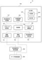
- FIG. 1 is a block diagram showing a configuration of an output system including an output device according to an embodiment of the present disclosure.
- FIG. 2 is a block diagram showing a configuration of a servo control device.
- FIG. 1 is a block diagram showing a filter configured by connecting a plurality of notch filters in series.
- FIG. 13 is a diagram showing a display screen of a liquid crystal display device that displays frequency characteristics, control parameters, and evaluation indexes. 13 is a diagram showing an example of a frequency characteristic being adjusted and judged as "NG" that is displayed in a display area of a display screen.
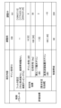
- FIG. 6A and 6B are diagrams showing an example of display of control parameters and evaluation indexes before and during adjustment, corresponding to the display example of FIG.
- FIG. 2 is a configuration diagram showing a mechanical model of a two-inertia system.
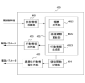
- FIG. 1 is a block diagram showing a configuration of a machine learning device.
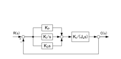
- FIG. 1 is a diagram showing a reference model of a servo control device having ideal characteristics without resonance.
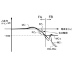
- FIG. 10 is a characteristic diagram showing frequency characteristics of input/output gains of a reference model servo control device and servo control devices before and after learning;
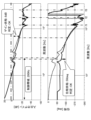
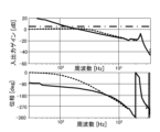
- FIG. FIG. 4 is a Bode diagram showing an example of frequency characteristics. 4 is a flowchart showing the operation of the output device. 5 is a diagram showing a display screen of a liquid crystal display device which displays the frequency characteristics of a filter in addition to the display screen shown in FIG. 4 .
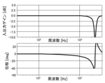
- FIG. 13 is a diagram showing the frequency characteristics of a filter before adjustment of the filter coefficients.
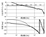
- FIG. 4 is a diagram showing the frequency characteristics of the servo control device before adjustment of the filter coefficients.
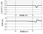
- FIG. 13 is a diagram showing the frequency characteristics of a first-stage filter during adjustment of the filter coefficient;
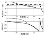
- FIG. 13 is a diagram showing the frequency characteristics of the servo control device during adjustment of the coefficient of the first-stage filter.
- FIG. 13 is a diagram showing the frequency characteristics of a filter during adjustment of the coefficient of the second-stage filter.
- FIG. 13 is a diagram showing the frequency characteristics of the servo control device during adjustment of the coefficient of the second-stage filter.
- FIG. 13 is a diagram showing frequency characteristics of a filter during adjustment of the coefficients of the first and second filter stages.
- FIG. 11 is a diagram showing the frequency characteristics of the servo control device during adjustment of the coefficients of the first and second filter stages.
- FIG. 1 is a block diagram showing a configuration of an output system including an output device according to an embodiment of the present disclosure.
- the output system 10 includes an output device 100 that outputs frequency characteristics and an evaluation index of the entire system of the servo control device 200, the servo control device 200, and a frequency characteristic measuring device 300 that measures frequency characteristics of the entire system of the servo control device 200 based on input/output signals of the servo control device 200.
- the frequency characteristic measuring device 300 may be included in the output device 10.
- the output device 100 may be included in the servo control device 200.
- the output device 100 adjusts the control parameters of the components of the servo control device 200, for example at least one of the gain parameters and the filter parameters, using the frequency characteristics of the entire system output from the frequency characteristic measuring device 300, and outputs the frequency characteristics and evaluation index of the entire system of the servo control device 200 being adjusted.
- a servo control device 200 and a frequency characteristic measuring device Prior to describing the output device 100, a servo control device 200 and a frequency characteristic measuring device will be described.
- FIG. 2 is a block diagram showing the configuration of the servo control device. As shown in FIG. 2, the servo control device 200 includes a subtractor 201 , a controller 202 , a filter 203 , and a controlled object 204 .
- Subtractor 201 finds the difference between the input control command and the feedback value from control object 204, and outputs this difference as a deviation to controller 202.
- the control command is a speed command
- the feedback value is a speed feedback value from a motor included in control object 204
- the deviation is a speed deviation.
- a sine wave signal with a changed frequency is input as a control command to the subtractor 201.
- the sine wave signal with a changed frequency is input from a higher-level device, but the servo control device 200 may also include a frequency generating unit that generates a sine wave signal with a changed frequency.
- the control command and the feedback value are input to a frequency characteristic measuring unit 300.
- the controller 202 adds together a value obtained by multiplying the deviation by an integral gain k i and integrating the result, and a value obtained by multiplying the deviation by a proportional gain k p , and further multiplies the result by a gain k, and outputs the result as a torque command to the filter 203.
- the controller 202 is, for example, a speed controller.
- multiple notch filters are used for the filter 203.
- multiple resonance points exist, and resonance may increase in the servo control device 200.
- the multiple resonances can be reduced.
- a torque command is output from the filter 203 to the control target 204.
- FIG. 3 is a block diagram showing a filter configured by connecting a plurality of notch filters in series.
- filter 203 when there are k resonance points (k is a natural number of 2 or more), filter 203 is configured by connecting m filters 203-1 to 203-m (m is a natural number of 2 or more, m ⁇ k) in series.
- m filters 203-1 to 203-m corresponds to a different frequency band.
- filter 203 will be described as being configured by three filters 203-1, 203-2, and 203-3 connected in series.
- the controlled object 204 is a motor and a mechanical part of a machine tool, a robot, or an industrial machine.
- the motor is driven based on a torque command.
- the feedback value from the control object 204 is a velocity feedback from a motor
- the feedback value can be the velocity detection value obtained by integrating the rotational angular velocity position detected by a rotary encoder (not shown) provided on the motor.
- the frequency characteristic measurement device 300 uses a control command (sine wave) serving as an input signal and a feedback (sine wave) serving as an output signal to determine the frequency characteristics of the amplitude ratio (input/output gain) between the input signal and the output signal and the phase delay for each frequency defined by the control command, and outputs the determined frequency characteristics to the output device 100.
- the determined frequency characteristics are the frequency characteristics Pc of a closed loop.
- the frequency characteristic measurement device 300 calculates the open loop frequency characteristic Po from this frequency characteristic Pc, and outputs the closed loop frequency characteristic Pc and the open loop frequency characteristic Po to the output device 100.
- the servo control device 200 and frequency characteristic measurement device 300 have been described above. Next, the output device 100 will be described.
- the output device 100 includes an information acquisition unit 101, an information output unit 102, a frequency characteristic storage unit 103, a parameter storage unit 104, a control unit 105, a parameter adjustment unit 106, a frequency characteristic calculation unit 107, an evaluation index calculation unit 108, and an output unit 109.
- the information output unit 102 may not be provided.
- the information acquisition unit 101 acquires the closed loop frequency characteristic Pc and the open loop frequency characteristic Po from the frequency characteristic measurement device 300.
- the control unit 105 stores the acquired closed loop frequency characteristic Pc and open loop frequency characteristic Po in the frequency characteristic storage unit 103.
- the information output unit 102 sets the optimal control parameters obtained by the adjustment by the parameter adjustment unit 106 in the servo control device 200.
- the control parameters are at least one of the integral gain k i , proportional gain k p , and gain k of the controller 202, and the attenuation bandwidth d, center frequency ⁇ n , and attenuation damping rate ⁇ of the transfer function of the filter 203.
- the frequency characteristic storage unit 103 stores the closed loop frequency characteristic Pc and the open loop frequency characteristic Po.
- the parameter storage unit 104 stores the control parameters of the servo control device 200 before adjustment, i.e., at least one of the integral gain k i , proportional gain k p , and gain k of the controller 202 , and the attenuation bandwidth d, center frequency ⁇ n , and attenuation damping rate ⁇ of the transfer function of the filter 203 .
- the control unit 105 controls the information acquisition unit 101, the information output unit 102, the frequency characteristic storage unit 103, the parameter storage unit 104, the parameter adjustment unit 106, the frequency characteristic calculation unit 107, the evaluation index calculation unit 108, and the output unit 109.
- the parameter adjustment unit 106 reads out the open loop frequency characteristic Po from the frequency characteristic storage unit 103 via the control unit 105.
- the parameter adjustment unit 106 also reads out the control parameters before adjustment from the parameter storage unit 104 via the control unit 105. Then, the parameter adjustment unit 106 adjusts the control parameters based on the read open loop frequency characteristic Po and the read control parameters, and outputs the control parameters being adjusted to the frequency characteristic calculation unit 107. Furthermore, the parameter adjustment section 106 re-adjusts the control parameters based on the frequency characteristics calculated by the frequency characteristic calculation section 107 , and outputs the re-adjusted control parameters to the frequency characteristic calculation section 107 .
- the parameter adjustment unit 106 can determine, for example, whether to adjust the control parameters again based on whether the resonance of the frequency characteristics calculated by the frequency characteristic calculation unit 107 has been suppressed.
- the frequency characteristic calculation unit 107 uses the control parameters adjusted by the parameter adjustment unit 106, the control parameters before adjustment read from the parameter memory unit 104 via the control unit 105, and the open loop frequency characteristic Po read from the frequency characteristic storage unit 103 via the control unit 105 to simulate the open loop and closed loop frequency characteristics of the servo control device 200, and outputs the found open loop frequency characteristic or the found open loop and closed loop frequency characteristics to the parameter adjustment unit 106.
- the frequency characteristic calculation unit 107 performs the same operation when the control parameters are adjusted again. If the frequency characteristic calculation unit 107 stores the control parameters and the open loop frequency characteristic Po before adjustment, it is not necessary to read out the control parameters and the open loop frequency characteristic Po before adjustment via the control unit 105. A method of simulating the frequency characteristic of the servo control device 200 using the adjusted control parameters will be described later.
- the control parameters are optimized by repeating the adjustment of the control parameters and the calculation of the frequency characteristics between the parameter adjustment unit 106 and the frequency characteristic calculation unit 107.
- the parameter adjustment unit 106 outputs the optimized control parameters to the information output unit 102.
- the evaluation index calculation unit 108 calculates an evaluation index based on the frequency characteristics of the open loop and closed loop calculated by the frequency characteristic calculation unit 107.
- the evaluation index is, for example, at least one of the gain margin, phase margin, and high-frequency maximum gain calculated based on the frequency characteristics of the open loop, and the closed loop maximum gain calculated based on the frequency characteristics of the closed loop.
- Gain margin indicates how much margin there is until the gain reaches 1x (0 dB) when the phase delay of the loop gain is 180 degrees.
- Phase margin indicates how far above 0 degrees (180 degrees in phase amount) the phase difference is at the frequency where the gain is 0 dB (i.e., it indicates the phase difference).
- the closed loop maximum gain indicates the maximum value of the gain characteristic of the closed loop frequency characteristics.
- the high frequency range maximum gain indicates the maximum value of the gain characteristic of the closed loop frequency characteristics at frequencies of 1000 Hz or higher.
- the control band (response band) indicates the frequency at which the phase delay in the closed loop characteristics is 90°.
- the output unit 109 includes a display unit such as a liquid crystal display device, a printer, or the like.
- the output unit 109 outputs the frequency characteristics calculated by the frequency characteristics calculation unit 107, the control parameters being adjusted, and the evaluation index calculated by the evaluation index calculation unit 108.
- the output unit 109 When the output unit 109 illustrates frequency characteristics and the like on a display unit such as a liquid crystal display device, the output unit 109 includes a drawing unit 1091 and a display unit 1092, as shown in FIG. 1.
- the drawing unit 1091 creates a gain diagram and a phase diagram of the frequency characteristics, and displays them in a display area 110A of the display screen of the display unit 1092 in FIG. 4, which will be described later.
- the drawing unit 1091 also draws a table of the control parameters and evaluation indexes, and displays them in a display area 110B of the display screen of the display unit 1092 in FIG. 4, which will be described later.
- the output unit 109 may store a plurality of frequency characteristics, control parameters, and evaluation indices before and during adjustment, and output a plurality of frequency characteristics, control parameters, and evaluation indices.
- the drawing unit 1091 can display a plurality of frequency characteristics, control parameters, and evaluation indices on one display screen on the display unit 1092.
- the drawing unit 1091 can display the changing frequency characteristics on the display unit 1092 by overlapping them with different display methods such as color, line type (solid line, dotted line, chain line, etc.), and line thickness.
- the drawing unit 1091 can display the changing frequency characteristics as a video on the display unit 1092.
- the drawing unit 1091 can create a diagram or video in which the progress of a plurality of frequency characteristics during adjustment is overlapped on the display screen, and display it on the display unit 1092.
- FIG. 4 is a diagram showing a display screen of a liquid crystal display device that displays frequency characteristics, control parameters, and evaluation indexes.
- the display screen 110 includes a display area 110A for displaying frequency characteristics, and a display area 110B.
- Fig. 5 is a diagram showing frequency characteristics during adjustment that are judged as "NG" and are displayed in the display area 110A.
- the solid curves in the gain diagram and phase diagram in Fig. 5 indicate the frequency characteristics of an open loop, and the dotted curves indicate the frequency characteristics of a closed loop.
- the dashed-dotted line in Fig. 5 indicates the maximum value of the gain of the closed loop frequency characteristics.
- f1, f2, and f3 shown by the two-dot dashed lines in Fig. 5 indicate the positions of the center frequencies ⁇ n of the filters 203-1, 203-2, and 203-3.
- FIG. 6 is a diagram showing the control parameters and evaluation indexes before and during adjustment, which are displayed in the display region 110B.
- the control parameters and evaluation indexes “before adjustment” in FIG. 6 are control parameters stored in the parameter storage unit 104 and evaluation indexes calculated using the open-loop frequency characteristic Po calculated by the frequency characteristic measurement apparatus 300.
- the control parameters and evaluation indexes "under adjustment” in Fig. 6 are evaluation indexes calculated by the evaluation index calculation unit 108 using the control parameters adjusted by the parameter adjustment unit 106 and the frequency characteristics of the open loop and closed loop calculated using the adjusted control parameters.
- the frequency characteristics of the open loop and closed loop used in calculating the evaluation indexes in Fig. 6 correspond to the frequency characteristics of the open loop and closed loop shown by the solid line and dotted line in Fig.
- the values in brackets [ ] in the evaluation index before adjustment column in Fig. 6 are required stability indexes that were set in advance before adjustment.
- the reason why the frequency characteristic in Fig. 5 is "NG" is that the values of the gain margin, phase margin, closed loop maximum gain, and high frequency region maximum gain, which are the stability indexes during adjustment in Fig. 6, are "-3", “-30", “6", and “-16", respectively, which do not satisfy the required stability indexes of "6", "30", "5", and "-20”, respectively, which are the gain margin, phase margin, closed loop maximum gain, and high frequency region maximum gain.
- the control band is not shown because it is unstable.
- FIG. 7 is a diagram showing frequency characteristics during adjustment that are judged to be "OK" and are displayed in display area 110A.
- FIG. 8 is a diagram showing control parameters and evaluation indices before and during adjustment and displayed in display area 110B.
- the explanation of the frequency characteristics in FIG. 7 and the control parameters and evaluation indices before and during adjustment in FIG. 8 will be omitted to the extent that they overlap with the explanation of the frequency characteristics in FIG. 5 and the control parameters and evaluation indices before and during adjustment in FIG. 6.
- the frequency characteristic in Figure 7 is considered “OK” because the values of the gain margin, phase margin, closed loop maximum gain, and high frequency region maximum gain, which are the stability indexes during adjustment in Figure 8, are "8", “50", “3", and "-18", respectively, and the values of the gain margin, phase margin, closed loop maximum gain, and high frequency region maximum gain, gain margin, and phase margin are "6", "30", "5", and "-20”, respectively.
- the parameter adjustment unit 106 reads out the open loop frequency characteristic Po from the frequency characteristic storage unit 103 via the control unit 105. The parameter adjustment unit 106 also reads out the control parameters before adjustment from the parameter storage unit 104 via the control unit 105. Then, the parameter adjustment unit 106 adjusts the control parameters based on the read open loop frequency characteristic Po and the read control parameters, and outputs the control parameters being adjusted to the frequency characteristic calculation unit 107. At the second or subsequent adjustment times, parameter adjustment section 106 readjusts the control parameters based on the frequency characteristics output from frequency characteristic calculation section 107 , and outputs the control parameters being readjusted to frequency characteristic calculation section 107 .
- the frequency characteristic calculation unit 107 calculates the frequency characteristic CF1 of the open loop from the controller 202 to the filter 203 of the servo control device 200 using the transfer function of the servo control device 200 using the control parameters before adjustment. Also, the frequency characteristic calculation unit 107 calculates the frequency characteristic CF2 of the open loop from the controller 202 to the filter 203 of the servo control device 200 using the transfer function from the controller 202 to the filter 203 of the servo control device 200 using the adjusted control parameters output from the parameter adjustment unit 106.
- the frequency characteristic calculation unit 107 calculates only the open-loop frequency characteristic CF2 from the controller 202 to the filter 203 of the servo control device 200 using the transfer function from the controller 202 to the filter 203 of the servo control device 200 using the adjusted control parameters output from the parameter adjustment unit 106 .
- the gain characteristic and phase characteristic of a general open loop frequency characteristic C of the servo control device 200 are shown in the following formula 2 (hereinafter, formula 2).
- the transfer function of the open loop of the servo control device 200 is indicated by Go(s).
- L O ( ⁇ ) indicates the gain characteristic of the open loop frequency characteristic
- ⁇ O ( ⁇ ) indicates the phase characteristic of the open loop frequency characteristic.
- the closed loop transfer function Gc(s) of the servo control device 200 can be calculated by the formula Go(s)/(1+Go(s)).
- the gain characteristic L C ( ⁇ ) of the frequency characteristic of the closed loop and the phase characteristic ⁇ C ( ⁇ ) of the frequency characteristic of the closed loop can be obtained by replacing L O ( ⁇ ) and Go(j ⁇ ) in Equation 2 with L C ( ⁇ ) and G C (j ⁇ ), and replacing ⁇ O ( ⁇ ) and Go(j ⁇ ) with ⁇ C ( ⁇ ) and G C (j ⁇ ).
- the frequency characteristic CF1 of the open loop from the controller 202 to the filter 203 of the servo control device 200 is a frequency characteristic when at least one control parameter of the transfer function C(s) of the controller and the transfer function F(s) of the filter is a control parameter before adjustment.
- the frequency characteristic CF2 of the open loop from the controller 202 to the filter 203 of the servo control device 200 is a frequency characteristic when at least one control parameter of the transfer function C(s) of the controller and the transfer function F(s) of the filter is a control parameter being adjusted.
- the difference between the frequency characteristic CF1 and the frequency characteristic CF2 is that at least one of the integral gain k i , proportional gain k p and gain k of the transfer function C(s) and the attenuation bandwidth d, center frequency ⁇ n and attenuation damping rate of the transfer function F(s) is different, which will be described later.
- the transfer function C(s) of the controller, the transfer function F(s) of the filter, and the transfer function P(s) of the controlled object are expressed as follows:
- the transfer function C(s) of the controller 202 is expressed by the following Equation 3 (Equation 3 below): In Equation 3, k i is an integral gain, k p is a proportional gain, and k is a gain.
- F 1 (s), F 2 (s), and F 3 (s) denote the transfer functions of the three filters 203-1 to 203-3.
- the transfer function F 1 (s) of the notch filter serving as the filter 203-1 is shown in the following Equation 4 (Equation 4 below).
- the transfer functions of the filters 203-2 and 203-3 are similarly shown in Equation 4.
- the coefficient d in Equation 4 indicates the attenuation bandwidth
- the coefficient ⁇ n indicates the central angular frequency
- the coefficient ⁇ indicates the attenuation damping rate.
- Equation 6 the transfer function P(s) of the controlled object 204 is expressed as a transfer function from the motor position to the load position by Equation 5 (hereinafter shown as Equation 6).
- Equation 5 JL is the load inertia
- Km is the spring constant
- Cm is the damper constant.
- the two-inertia mechanical model shown in FIG. 9 is described in, for example, “Research on Low-Frequency Vibration Suppression Control Using a Two-Inertia System Model for the Feed Axis of an NC Machine Tool,” Journal of the Japan Society for Precision Engineering, Vol. 82, No. 8, 2016, pp. 745-750.
- the parameter adjustment unit 106 is configured with a machine learning device, and can use machine learning (hereinafter, referred to as learning) when adjusting the control parameters based on the frequency characteristics calculated by the frequency characteristic calculation unit 107. Learning by the machine learning device is performed before shipment, but re-learning may be performed after shipment. The machine learning device repeats adjustment of the control parameters to find optimal values of the control parameters.
- An agent (corresponding to the machine learning device in this embodiment) observes the state of the environment, selects an action, and the environment changes based on the action. As the environment changes, some kind of reward is given, and the agent learns to select a better action (decision making). While supervised learning provides a perfect answer, in reinforcement learning the rewards are often fractional values based on some changes in the environment, so the agent learns to choose actions that maximize the sum of future rewards.
- reinforcement learning learns actions, and thus learns appropriate actions based on the interactions between the actions and the environment, that is, how to learn to maximize future rewards.
- any learning method can be used as the reinforcement learning, but in the following explanation, we will use as an example the case of using Q-learning, which is a method of learning a value Q(S, A) of selecting an action A in a certain environmental state S.
- Q-learning the objective is to select, from among possible actions A in a certain state S, the action A with the highest value Q(S, A) as the optimal action.
- Q(S, A) E[ ⁇ ( ⁇ t)rt].
- E[ ] represents the expected value
- t is time
- ⁇ is a parameter called the discount rate (described later)
- rt is the reward at time t
- ⁇ is the sum at time t.
- the expected value in this equation is the expected value when the state changes in accordance with the optimal action.
- reinforcement learning is performed while exploring by performing various actions.
- the update equation for such value Q(S, A) can be expressed, for example, by the following equation 6 (shown below as equation 6).
- St represents the state of the environment at time t
- At represents the action at time t.
- Action At changes the state to St+1.
- rt+1 represents the reward obtained by this change in state.
- the term with max is the Q value multiplied by ⁇ when action A with the highest Q value known at that time is selected in state St+1.
- ⁇ is a parameter with a range of 0 ⁇ 1 and is called the discount rate.
- ⁇ is a learning coefficient with a range of 0 ⁇ 1.
- the above-mentioned formula 6 represents a method for updating the value Q(St, At) of an action At in a state St based on the reward rt+1 returned as a result of a trial At.
- This update formula indicates that if the value of the best action in the next state St+1 by the action At, maxa Q(St+1,A), is greater than the value Q(St,At) of the action At in state St, Q(St,At) is increased, and conversely, if it is smaller, Q(St,At) is decreased.
- the value of a certain action in a certain state is brought closer to the value of the best action in the next state by it.
- the difference depends on the discount rate ⁇ and the reward rt+1, but basically, the value of the best action in a certain state is propagated to the value of the action in the state before that.
- one method is to create a table of Q(S, A) for all state-action pairs (S, A) and then perform learning.
- the number of states is too large to find the Q(S, A) values for all state-action pairs, and it takes a long time for Q-learning to converge.
- DQN Deep Q-Network
- the value function Q may be constructed using an appropriate neural network
- the value Q(S, A) may be calculated by approximating the value function Q with an appropriate neural network by adjusting the parameters of the neural network.
- Non-Patent Literature> Human-level control through deep reinforcement learning
- Volodymyr Mnih1 [online] [searched January 17, 2017]
- the machine learning device performs the Q-learning described above. Specifically, the machine learning device learns the value Q of selecting, as an action A, the adjustment of the control parameters of the servo control device 200 related to the state S, taking the control parameters of the servo control device 200 and the frequency characteristic output from the frequency characteristic calculation unit 107 as a state S.
- the control parameters of the servo control device 200 are at least one value of the coefficients k i , k p , and k of the transfer function of the controller 202, and the coefficients d, ⁇ n , and ⁇ of the transfer function of the filter 203.
- the machine learning device observes state information S including frequency characteristic Eo calculated using Equation 1 based on the control parameters of the servo control device 200, and determines action A.
- the machine learning device receives a reward every time it performs action A.
- the machine learning device for example, searches for the optimal action A by trial and error so as to maximize the total reward into the future. In this way, the machine learning device becomes able to select the optimal action A (i.e., the control parameters of the servo control device 200) for state S including frequency characteristic Eo, calculated based on the control parameters of the servo control device 200.
- FIG. 10 is a block diagram showing the configuration of a machine learning device. 10 , in order to perform the above-described reinforcement learning, machine learning device 400 includes state information acquisition unit 401, learning unit 402, behavior information output unit 403, value function storage unit 404, and optimized behavior information output unit 405. Learning unit 402 includes reward output unit 4021, value function update unit 4022, and behavior information generation unit 4023.
- the state information acquisition unit 401 acquires the state S including the frequency characteristic from the frequency characteristic calculation unit 107 based on the control parameters of the servo control device 200. This state information S corresponds to the environmental state S in Q-learning. The state information acquisition unit 401 outputs the acquired state information S to the learning unit 402 .
- the control parameters of the servo control device 200 at the time when Q-learning is first started are generated in advance by the user and stored in the parameter storage unit 104.
- the control parameters of the servo control device 200 generated by the user are adjusted to optimal ones by reinforcement learning.
- the control parameters of the servo control device 200 may be machine-learned using the adjusted values as initial values.
- the learning unit 402 is a part that learns the value Q(S, A) when a certain action A is selected under a certain environmental state S.
- the reward output unit 4021 is a part that calculates a reward when action A is selected in a certain state S.
- the reward output unit 4021 compares the measured or calculated input-output gain Gs with the input-output gain Gb of a preset reference model for each frequency. When the measured or calculated input-output gain Gs is greater than the input-output gain Gb of the reference model, the reward output unit 4021 gives a negative reward.
- the reward output unit 4021 gives a positive reward when the phase lag becomes smaller, a negative reward when the phase lag becomes larger, and a zero reward when the phase lag does not change.
- the reward output unit 4021 stores a reference model of the input/output gain.
- the reference model is a model of a servo control device having ideal characteristics without resonance.
- the reference model can be calculated from the inertia Ja, torque constant Kt, proportional gain Kp, integral gain KI, and differential gain KD of the model shown in FIG. 11.
- the inertia Ja is the sum of the motor inertia and the machine inertia.
- FIG. 12 is a characteristic diagram showing the frequency characteristics of the input/output gain between the servo control device of the reference model and the servo control device 200 before and after learning.
- the reference model has region A, which is a frequency region where the ideal input/output gain is equal to or greater than a certain input/output gain, for example, -20 dB or greater, and region B, which is a frequency region where the input/output gain is less than the certain input/output gain.
- region A of FIG. 12 the ideal input/output gain of the reference model is shown by curve MC1 (thick line).
- the ideal virtual input/output gain of the reference model is shown by curve MC11 (thick dashed line), and the input/output gain of the reference model is a constant value and shown by straight line MC12 (thick line).
- curves RC1 and RC2 the curves of the input/output gain with the servo control unit before and after learning are shown by curves RC1 and RC2, respectively.
- reward output unit 4021 gives a first negative reward when curve RC1 of the measured input/output gain before learning exceeds curve MC1 of the ideal input/output gain of the reference model.
- region B exceeding the frequency where the input/output gain becomes sufficiently small, even if the curve RC1 of the input/output gain before learning exceeds the curve MC11 of the ideal virtual input/output gain of the reference model, the influence on stability is small. Therefore, in region B, as described above, the input/output gain of the reference model uses the straight line MC12 of a constant input/output gain (for example, -20 dB) rather than the curve MC11 of the ideal gain characteristic. However, if the curve RC1 of the measured input/output gain before learning exceeds the straight line MC12 of the constant input/output gain, there is a possibility of instability, so a first negative value is given as a reward.
- the phase delay which is a state variable related to state information S
- D(S) the phase delay, which is a state variable related to state S', which has changed from state S due to action information A (adjustment of the control parameters of the servo control device 200)
- D(S') the phase delay, which is a state variable related to state S', which has changed from state S due to action information A (adjustment of the control parameters of the servo control device 200).
- the method by which the reward output unit 4021 determines the reward based on the phase lag information is, for example, as follows.
- the method for determining the reward based on the phase lag information is not particularly limited to the method described below.
- the reward is determined based on whether the frequency at which the phase delay is 180 degrees increases, decreases, or remains the same.
- the case where the phase delay is 180 degrees is taken up, but it is not limited to 180 degrees and may be another value.
- the phase lag is shown in the phase diagram of the Bode diagram shown in Fig. 13
- the curve changes from state S to state S' so that the frequency at which the phase lag is 180 degrees becomes smaller in the X2 direction in Fig. 13
- the phase lag becomes larger.
- the curve changes from state S to state S' so that the frequency at which the phase lag is 180 degrees becomes larger in the X1 direction in Fig. 13
- the phase lag becomes smaller.
- phase lag D(S) is defined as ⁇ phase lag D(S'), and the reward output unit 4021 sets the reward value to a second negative value.
- the absolute value of the second negative value is set to be smaller than the first negative value.
- the phase lag D(S) is defined as > phase lag D(S'), and the reward output unit 4021 sets the reward value to a positive value.
- phase lag D(S) D(S')
- the reward output unit 4021 sets the reward value to zero.
- the negative value when it is defined that the phase lag D(S') of state S' after action A is performed is larger than the phase lag D(S) in the previous state S, the negative value may be increased according to the ratio. For example, in the above-mentioned method, the negative value may be increased according to the degree to which the frequency has decreased. Conversely, as a positive value when it is defined that the phase lag D(S') of state S' after action A is performed is smaller than the phase lag D(S) in the previous state S, the positive value may be increased according to the ratio. For example, in the first method described above, the positive value may be increased according to the degree to which the frequency has increased.
- Value function update unit 4022 updates value function Q stored in value function memory unit 404 by performing Q learning based on state S, action A, state S' when action A is applied to state S, and the reward value calculated as described above.
- the value function Q may be updated by online learning, batch learning, or mini-batch learning.
- Online learning is a learning method in which a certain action A is applied to the current state S, and the value function Q is updated immediately each time the state S transitions to a new state S'.
- batch learning is a learning method in which a certain action A is applied to the current state S, and the state S transitions to a new state S' is repeatedly performed, thereby collecting learning data, and updating the value function Q using all of the collected learning data.
- mini-batch learning is a learning method intermediate between online learning and batch learning, in which the value function Q is updated each time a certain amount of learning data is accumulated.
- the behavior information generating unit 4023 selects behavior A in the Q-learning process for the current state S.
- the behavior information generating unit 4023 generates behavior information A and outputs the generated behavior information A to the behavior information output unit 403 in order to perform an operation of changing a control parameter of the servo control device 200 in the Q-learning process (corresponding to behavior A in Q-learning). More specifically, the behavior information generating unit 4023, for example, incrementally adds or subtracts the control parameter of the servo control device 200 included in behavior A from the control parameter of the servo control device 200 included in state S.
- the behavior information generating unit 4023 may apply an increase or decrease in the control parameters of the servo control device 200 to transition to state S', and if a positive reward (a reward with a positive value) is returned, the behavior information generating unit 4023 may take a measure to select the next behavior A' such that the measured phase delay is smaller than the previous phase delay, such as incrementally adding or subtracting from the control parameters of the servo control device 200 as in the previous action.
- the behavioral information generating unit 4023 may take measures to select the next behavior A' such that, for example, the control parameters of the servo control device 200 are incrementally subtracted or added in the opposite manner to the previous action, so that if the measured or calculated input/output gain is greater than the input/output gain of the reference model, the input gain difference is smaller than the previous one, or the measured phase lag is smaller than the previous phase lag.
- the behavior information output unit 403 is a part that transmits the behavior information A output from the learning unit 402 to the frequency characteristic calculation unit 107.
- the frequency characteristic calculation unit 107 changes the current state S, i.e., the currently set control parameters of the servo control device 200, based on this behavior information, thereby transitioning to the next state S' (i.e., the changed control parameters of the servo control device 200).
- the value function storage unit 404 is a storage device that stores the value function Q.
- the value function Q may be stored as a table (hereinafter referred to as an action value table) for each state S and action A, for example.
- the value function Q stored in the value function storage unit 404 is updated by the value function update unit 4022.
- the value function Q stored in the value function storage unit 404 may be shared with other machine learning devices 400. If the value function Q is shared by multiple machine learning devices 400, it becomes possible to perform reinforcement learning in a distributed manner among the machine learning devices 400, thereby improving the efficiency of reinforcement learning.
- the control parameters are modified based on this behavioral information.
- the machine learning device 400 can optimize the control parameters of the servo control device 200 and operate to suppress vibrations at the machine end.
- the machine learning device 400 uses machine learning to sequentially find optimal values for the control parameters (at least one of the coefficient ⁇ , the coefficient ⁇ n , and the coefficient d) of each of the multiple filters that attenuate the resonance point.
- FIG. 14 is a flowchart showing the operation of the output device.
- step S11 the control unit 105 stores in the frequency characteristic storage unit 103 the closed loop frequency characteristics and open loop frequency characteristics of the input/output gain and phase delay output from the frequency characteristic measurement device 300.
- step S12 the control unit 105 reads the open loop frequency characteristics from the frequency characteristic storage unit 103, and reads the control parameters before adjustment from the parameter storage unit 104.
- step S13 the parameter adjustment unit 106 adjusts the control parameters and outputs the adjusted control parameters to the frequency characteristic calculation unit 107.
- step S14 the frequency characteristic calculation unit 107 performs a simulation to determine the open loop frequency characteristics of the servo control device 200 using the adjusted control parameters, and also determines the closed loop frequency characteristics.
- step S15 the evaluation index calculation unit 108 calculates the evaluation index based on both the open loop frequency characteristics and the closed loop frequency characteristics.
- step S16 the output unit 109 displays the frequency characteristics and the evaluation index.
- step S17 the parameter adjustment unit 106 judges whether or not to perform readjustment. If readjustment is to be performed, the process returns to step S13. If readjustment is not to be performed, the process ends.
- the present embodiment described above when adjusting the control parameters of a servo control device, it is sufficient to measure the frequency characteristics once, and the frequency characteristics when the control parameters are adjusted can be obtained by simulation. According to the present embodiment, by checking multiple frequency characteristics and/or evaluation indices of multiple frequency characteristics, it is possible to easily compare the frequency characteristics and/or evaluation indices of the frequency characteristics being adjusted, and to determine the control parameters to be applied.
- the output unit 109 may add and display the frequency characteristic of the filter on the display screen 110 shown in Fig. 4.
- the frequency characteristic calculation unit 107 calculates the frequency characteristic of the filter using the adjusted control parameters and outputs it to the output unit 109.
- the frequency characteristic of the filter composed of three notch filters is expressed by Equation 7 (Equation 7 below).
- L F ( ⁇ ) indicates the gain characteristic of the frequency characteristic of the filter
- ⁇ F ( ⁇ ) indicates the phase characteristic of the frequency characteristic of the filter.
- FIG. 15 is a diagram showing a display screen of a liquid crystal display device that displays the frequency characteristics of a filter in addition to the frequency characteristics, control parameters, and evaluation indexes.
- the display screen 110 includes a display area 110A for displaying frequency characteristics, a display area 110B, and a display area 110C.
- the position of the display area 110B in Fig. 15 is different from the position of the display area 110B shown in Fig. 4 .
- the display area 110C displays the frequency characteristics of the filter.
- Examples of the frequency characteristics of the servo control device and the filter before and during adjustment of the filter coefficients are shown in Figures 16 to 23.
- the frequency characteristics of the servo control device are displayed in display area 110A, and the frequency characteristics of the filter are displayed in display area 110C.
- 16 and 17 are diagrams showing the frequency characteristics of a filter and a servo control device before the filter coefficients are adjusted.
- 18 and 19 are diagrams showing the frequency characteristics of the filter and the servo control device during adjustment of the coefficient of the first-stage filter 203-1.
- 20 and 21 are diagrams showing the frequency characteristics of the filter and the servo control device during adjustment of the coefficient of the second-stage filter 203-2.
- 22 and 23 are diagrams showing the frequency characteristics of the filters and the frequency characteristics of the servo control device during adjustment of the coefficients of the first and second stage filters 203-1 and 203-2.
- the filter 203 shown in FIG. 2 is not limited to being composed of multiple notch filters, and may be composed of, for example, one notch filter, or may be composed of three filters: a first-order low-pass filter, a second-order low-pass filter, and a notch filter.
- the output device 100 can be configured in the same way as the present embodiment already described, except that the three filters 203-1 to 203-3 are replaced with a first-order low-pass filter, a second-order low-pass filter, and a notch filter instead of the three notch filters.
- Equation 8 The transfer functions F 1LPF (s), F 2LPF (s) and F n (s) are expressed by the following Equation 8 (Equation 8 below):
- the coefficient d is the attenuation bandwidth
- the coefficient ⁇ n is the angular center frequency
- the coefficient ⁇ is the attenuation damping rate
- T is the time constant.
- the frequency characteristics (gain characteristics and phase characteristics) of a filter composed of a first-order low-pass filter, a second-order low-pass filter, and a notch filter can be obtained by replacing F 1 (j ⁇ ), F 2 (j ⁇ ), and F 3 (j ⁇ ) in equation 7 (equation 7 below) with F 1LPF (j ⁇ ), F 2LPF (j ⁇ ), and F n (j ⁇ ).
- the frequency characteristic of the filter is displayed in a display area 110C of the display screen shown in FIG.
- the components included in the output device 100 of each of the above-described embodiments can be realized by hardware, software, or a combination of these.
- being realized by software means being realized by a computer reading and executing a program.
- the output device 100 includes a processor such as a CPU (Central Processing Unit).
- the processor functions as an execution unit.
- the output device 100 also includes a secondary storage device such as a HDD (Hard Disk Drive) that stores various control programs such as application software or an OS (Operating System), and a primary storage device such as a RAM (Random Access Memory) for storing data temporarily required for the processor to execute a program.
- a processor such as a CPU (Central Processing Unit).
- the processor functions as an execution unit.
- the output device 100 also includes a secondary storage device such as a HDD (Hard Disk Drive) that stores various control programs such as application software or an OS (Operating System), and a primary storage device such as a RAM (Random Access Memory) for storing data temporarily required
- the output device 100 performs calculations based on the application software or OS while the arithmetic processing unit reads the application software or OS from the auxiliary storage device and deploys the read application software or OS in the main storage device. Also, based on the results of this calculation, the output device 100 controls various hardware devices. In this way, the functional blocks of this embodiment are realized.
- the components included in the output device 100 can be realized by hardware including electronic circuits, etc.
- some or all of the functions of each component included in the output device 100 can be configured by integrated circuits (ICs), such as ASICs (Application Specific Integrated Circuits), gate arrays, FPGAs (Field Programmable Gate Arrays), and CPLDs (Complex Programmable Logic Devices).
- ICs integrated circuits
- ASICs Application Specific Integrated Circuits
- FPGAs Field Programmable Gate Arrays
- CPLDs Complex Programmable Logic Devices
- Non-transitory computer readable media include various types of tangible storage media. Examples of non-transitory computer readable media include magnetic recording media (e.g., hard disk drives), magneto-optical recording media (e.g., magneto-optical disks), CD-ROM (Read Only Memory), CD-R, CD-R/W, and semiconductor memory (e.g., mask ROM, PROM (Programmable ROM), EPROM (Erasable PROM), flash ROM, and RAM (random access memory)).
- the program may also be provided to the computer by various types of transitory computer readable media.
- the effect of the above-described embodiment and modified example is that it is possible to obtain by simulation how the characteristics and evaluation indexes of the entire system of the servo control device change by adjusting parameters such as the gain or filter of the servo control device.
- An output device comprising:
- the frequency characteristic calculation unit (107) calculates a frequency characteristic of a filter included in the servo control device using the adjusted control parameters, The output device according to claim 1, wherein the output unit (109) outputs a frequency characteristic of the filter.
- the output device includes a display unit (1092) that displays the frequency characteristics being adjusted and the evaluation indexes for evaluating each of the frequency characteristics side by side or on top of each other on a display screen, or displays them as a moving image.
- Appendix 4 The output device described in Appendix 3, wherein the output unit includes a drawing unit (1091) that creates a diagram or video in which the transitions of the multiple frequency characteristics being adjusted are superimposed on the display screen, and the display unit (1092) displays the diagram or video created by the drawing unit.
- the output unit includes a drawing unit (1091) that creates a diagram or video in which the transitions of the multiple frequency characteristics being adjusted are superimposed on the display screen, and the display unit (1092) displays the diagram or video created by the drawing unit.
- An output device according to any one of claims 1 to 5, comprising a frequency characteristic measuring device (300) for measuring the frequency characteristics of the entire system of the servo control device before adjustment.
- An output device (100) according to any one of Supplementary Notes 1 to 6;
- a servo control device (200) for controlling a motor that drives an axis of a machine tool, a robot, or an industrial machine;
- a frequency characteristic measuring device (300) for measuring the frequency characteristic of the entire system of the servo control device before adjustment;
- An output system comprising:
- Output system 100 Output device 101 Information acquisition unit 102 Information output unit 103 Frequency characteristic storage unit 104 Parameter storage unit 105 Control unit 106 Parameter adjustment unit 107 Frequency characteristic calculation unit 108 Evaluation index calculation unit 109 Output unit 110 Display screen 200 Servo control device 201 Subtractor 202 Controller 203 Filter 204 Control target 300 Frequency characteristic measurement device 400 Machine learning device
Landscapes
- Engineering & Computer Science (AREA)
- Power Engineering (AREA)
- Feedback Control In General (AREA)
Abstract
サーボ制御装置のゲイン又はフィルタ等のパラメータの調整によって、サーボ制御装置の系全体の特性及び評価指標がどのように変化するかをシミュレーションで求める。 工作機械、ロボット又は産業機械の軸を駆動するモータを制御するサーボ制御装置に対して設けられる出力装置が、調整前のサーボ制御装置の系全体の周波数特性と、調整中のサーボ制御装置の制御パラメータとを用いて、制御パラメータを更新するパラメータ調整部と、更新した制御パラメータを用いて、調整中のサーボ制御装置の系全体の周波数特性を計算する周波数特性計算部と、調整中のサーボ制御装置の系全体の周波数特性を評価する指標を計算する評価指標計算部と、調整中の周波数特性と評価指標を出力する出力部と、を備える。
Description
本開示は、工作機械、ロボット又は産業機械の軸を駆動するモータを制御するサーボ制御装置に対して設けられる出力装置、出力装置を含む出力システム、及び出力方法に関する。
機械学習により、工作機械、ロボット又は産業機械のモータを制御するサーボ制御装置のゲイン又はフィルタのパラメータ等を調整する場合に、機械学習中又は機械学習後のゲイン又はフィルタ等のパラメータ調整過程をユーザに提供する技術が特許文献1に記載されている。
特許文献1には、機械学習中又は機械学習後のパラメータを取得して、このパラメータをユーザが分かりやすい情報に変えて出力する出力装置が記載されている。
具体的には、特許文献1には、工作機械、ロボット又は産業機械の軸を駆動するサーボモータを制御するサーボ制御装置に対して機械学習を行う機械学習装置から、学習中又は学習された、サーボ制御装置の構成要素のパラメータ又は第1の物理量を取得する情報取得部と、取得した第1の物理量と取得したパラメータから求めた第2の物理量とのいずれか1つの物理量、サーボ制御装置の構成要素の時間応答特性、及びサーボ制御装置の構成要素の周波数応答特性のうちの少なくとも1つを出力する出力部と、を備え、時間応答特性及び周波数応答特性は、パラメータ、第1の物理量又は第2の物理量を用いて求める出力装置が記載されている。物理量は、例えば、フィルタの中心周波数、帯域幅、及び減衰係数である。
具体的には、特許文献1には、工作機械、ロボット又は産業機械の軸を駆動するサーボモータを制御するサーボ制御装置に対して機械学習を行う機械学習装置から、学習中又は学習された、サーボ制御装置の構成要素のパラメータ又は第1の物理量を取得する情報取得部と、取得した第1の物理量と取得したパラメータから求めた第2の物理量とのいずれか1つの物理量、サーボ制御装置の構成要素の時間応答特性、及びサーボ制御装置の構成要素の周波数応答特性のうちの少なくとも1つを出力する出力部と、を備え、時間応答特性及び周波数応答特性は、パラメータ、第1の物理量又は第2の物理量を用いて求める出力装置が記載されている。物理量は、例えば、フィルタの中心周波数、帯域幅、及び減衰係数である。
ユーザは、サーボ制御装置のゲイン又はフィルタ等の制御パラメータの調整によって、サーボ制御装置の系全体の周波数特性と評価指標がどのように変化するかを知りたい場合がある。
しかし、ゲイン、フィルタ等の制御パラメータを調整して実際に周波数特性を求めるプロセスを繰り返すことは、多大な時間がかかる。
よって、ゲイン、フィルタ等の制御パラメータを調整する場合に、サーボ制御装置の系全体の周波数特性と評価指標がどのように変化するかをシミュレーションで求めることが望まれている。
しかし、ゲイン、フィルタ等の制御パラメータを調整して実際に周波数特性を求めるプロセスを繰り返すことは、多大な時間がかかる。
よって、ゲイン、フィルタ等の制御パラメータを調整する場合に、サーボ制御装置の系全体の周波数特性と評価指標がどのように変化するかをシミュレーションで求めることが望まれている。
本開示の代表的な第1の態様は、工作機械、ロボット又は産業機械の軸を駆動するモータを制御するサーボ制御装置に対して設けられる出力装置であって、
調整前の前記サーボ制御装置の系全体の周波数特性を保存する周波数特性保存部と、
調整前の制御パラメータを記憶するパラメータ記憶部と、
調整前の前記サーボ制御装置の系全体の周波数特性と、調整前の前記制御パラメータとを用いて、前記制御パラメータを調整するパラメータ調整部と、
調整した前記制御パラメータを用いて、調整中の前記サーボ制御装置の系全体の周波数特性を計算する周波数特性計算部と、
前記調整中の前記サーボ制御装置の系全体の周波数特性を評価する指標を計算する評価指標計算部と、
前記調整中の、前記サーボ制御装置の系全体の周波数特性と前記評価指標を出力する出力部と、
を備えた出力装置である。
調整前の前記サーボ制御装置の系全体の周波数特性を保存する周波数特性保存部と、
調整前の制御パラメータを記憶するパラメータ記憶部と、
調整前の前記サーボ制御装置の系全体の周波数特性と、調整前の前記制御パラメータとを用いて、前記制御パラメータを調整するパラメータ調整部と、
調整した前記制御パラメータを用いて、調整中の前記サーボ制御装置の系全体の周波数特性を計算する周波数特性計算部と、
前記調整中の前記サーボ制御装置の系全体の周波数特性を評価する指標を計算する評価指標計算部と、
前記調整中の、前記サーボ制御装置の系全体の周波数特性と前記評価指標を出力する出力部と、
を備えた出力装置である。
本開示の代表的な第2の態様は、上記の第1の態様の出力装置と、
工作機械、ロボット又は産業機械の軸を駆動するモータを制御するサーボ制御装置と、
調整前の前記サーボ制御装置の系全体の周波数特性を測定する周波数特性測定装置と、
を備えた出力システムである。
工作機械、ロボット又は産業機械の軸を駆動するモータを制御するサーボ制御装置と、
調整前の前記サーボ制御装置の系全体の周波数特性を測定する周波数特性測定装置と、
を備えた出力システムである。
本開示の代表的な第3の態様は、工作機械、ロボット又は産業機械の軸を駆動するモータを制御するサーボ制御装置に対して設けられる出力装置としてのコンピュータが、
調整前の前記サーボ制御装置の系全体の周波数特性を保存する処理と、
調整前の前記サーボ制御装置の系全体の周波数特性と、調整前の前記前記サーボ制御装置の制御パラメータとを用いて、前記制御パラメータを調整する処理と、
調整した前記制御パラメータを用いて、調整中の前記サーボ制御装置の系全体の周波数特性を計算する処理と、
前記調整中の前記サーボ制御装置の系全体の周波数特性を評価する指標を計算する処理と、
前記調整中の、前記サーボ制御装置の系全体の周波数特性と前記評価指標を出力する処理と、
を実行する、出力方法である。
調整前の前記サーボ制御装置の系全体の周波数特性を保存する処理と、
調整前の前記サーボ制御装置の系全体の周波数特性と、調整前の前記前記サーボ制御装置の制御パラメータとを用いて、前記制御パラメータを調整する処理と、
調整した前記制御パラメータを用いて、調整中の前記サーボ制御装置の系全体の周波数特性を計算する処理と、
前記調整中の前記サーボ制御装置の系全体の周波数特性を評価する指標を計算する処理と、
前記調整中の、前記サーボ制御装置の系全体の周波数特性と前記評価指標を出力する処理と、
を実行する、出力方法である。
以下、本開示の実施形態について図面を用いて詳細に説明する。
図1は本開示の一実施形態の出力装置を含む出力システムの構成を示すブロック図である。
図1に示すように、出力システム10は、サーボ制御装置200の系全体の周波数特性及び評価指標を出力する出力装置100、サーボ制御装置200、及びサーボ制御装置200の入出力信号に基づいて、サーボ制御装置200の系全体の周波数特性を測定する周波数特性測定装置300を備えている。周波数特性測定装置300は、出力装置10に含まれていてもよい。出力装置100は、サーボ制御装置200に含まれていてもよい。
出力装置100は、周波数特性測定装置300から出力される系全体の周波数特性に用いて、サーボ制御装置200の構成要素の制御パラメータ、例えば、ゲインのパラメータと、フィルタのパラメータとの少なくとも1つを調整し、調整中のサーボ制御装置200の系全体の周波数特性及び評価指標を出力する。
出力装置100の説明に先立って、サーボ制御装置200及び周波数特性測定装置について説明する。
図1は本開示の一実施形態の出力装置を含む出力システムの構成を示すブロック図である。
図1に示すように、出力システム10は、サーボ制御装置200の系全体の周波数特性及び評価指標を出力する出力装置100、サーボ制御装置200、及びサーボ制御装置200の入出力信号に基づいて、サーボ制御装置200の系全体の周波数特性を測定する周波数特性測定装置300を備えている。周波数特性測定装置300は、出力装置10に含まれていてもよい。出力装置100は、サーボ制御装置200に含まれていてもよい。
出力装置100は、周波数特性測定装置300から出力される系全体の周波数特性に用いて、サーボ制御装置200の構成要素の制御パラメータ、例えば、ゲインのパラメータと、フィルタのパラメータとの少なくとも1つを調整し、調整中のサーボ制御装置200の系全体の周波数特性及び評価指標を出力する。
出力装置100の説明に先立って、サーボ制御装置200及び周波数特性測定装置について説明する。
(サーボ制御装置200)
図2はサーボ制御装置の構成を示すブロック図である。
図2に示すように、サーボ制御装置200は、減算器201、制御器202、フィルタ203及び制御対象204を備えている。
図2はサーボ制御装置の構成を示すブロック図である。
図2に示すように、サーボ制御装置200は、減算器201、制御器202、フィルタ203及び制御対象204を備えている。
減算器201は、入力された制御指令と制御対象204からのフィードバック値との差を求め、その差を偏差として制御器202に出力する。例えば、制御指令は速度指令であり、フィードバック値は制御対象204に含まれるモータからの速度フィードバック値であり、偏差は速度偏差である。
減算器201には、周波数を変化させた正弦波信号が制御指令として入力される。周波数を変化させた正弦波信号は、上位装置から入力されるが、サーボ制御装置200が周波数を変化させた正弦波信号を生成する周波数生成部を備えていてもよい。制御指令及びフィードバック値は、周波数特性測定部300に入力される。
制御器202は、偏差に積分ゲインkiを乗じて積分した値と、偏差に比例ゲインkpを乗じた値とを加算し、更にゲインkを掛けた値を、トルク指令としてフィルタ203に出力する。制御器202は、例えば速度制御器である。
制御器202は、偏差に積分ゲインkiを乗じて積分した値と、偏差に比例ゲインkpを乗じた値とを加算し、更にゲインkを掛けた値を、トルク指令としてフィルタ203に出力する。制御器202は、例えば速度制御器である。
フィルタ203は、例えば複数のノッチフィルタが用いられる。モータで駆動される工作機械、ロボット又は産業機械では複数の共振点が存在し、サーボ制御装置200で共振が増大する場合がある。複数のノッチフィルタを用いることで複数の共振を低減することができる。フィルタ203からトルク指令が制御対象204に出力される。
図3は、複数のノッチフィルタの直列接続で構成されたフィルタを示すブロック図である。
図3において、k個(kは2以上の自然数)の共振点がある場合に、フィルタ203は、m個のフィルタ203-1~203-m(mは2以上の自然数でm<kとなる)を直列接続して構成する。m個のフィルタ203-1~203-mは、それぞれ異なる周波数帯域に対応している。以下、フィルタ203は、直列接続された3つのフィルタ203-1、203-2及び203-3により構成されるとして説明を行う。
図3において、k個(kは2以上の自然数)の共振点がある場合に、フィルタ203は、m個のフィルタ203-1~203-m(mは2以上の自然数でm<kとなる)を直列接続して構成する。m個のフィルタ203-1~203-mは、それぞれ異なる周波数帯域に対応している。以下、フィルタ203は、直列接続された3つのフィルタ203-1、203-2及び203-3により構成されるとして説明を行う。
制御対象204は、モータ、及び工作機械、ロボット又は産業機械の機構部である。モータは、トルク指令に基づいて駆動される。
制御対象204からのフィードバック値が、モータからの速度フィードバックである場合は、フィードバック値は、モータに設けられたロータリーエンコーダ(図示せず)によって検出される回転角速度位置を積分した速度検出値を速度フィードバック値とすることができる。
制御対象204からのフィードバック値が、モータからの速度フィードバックである場合は、フィードバック値は、モータに設けられたロータリーエンコーダ(図示せず)によって検出される回転角速度位置を積分した速度検出値を速度フィードバック値とすることができる。
(周波数特性測定装置)
周波数特性測定装置300は、入力信号となる制御指令(正弦波)と、出力信号となるフィードバック(正弦波)とを用いて、制御指令により規定される周波数ごとに、入力信号と出力信号との振幅比(入出力ゲイン)と位相遅れとの周波数特性を求めて出力装置100に出力する。求めた周波数特性は、閉ループの周波数特性Pcである。
また、周波数特性測定装置300は、この周波数特性Pcから開ループ周波数特性Poを計算して、閉ループの周波数特性Pc及び開ループ周波数特性Poを出力装置100に出力する。開ループ周波数特性Poは、閉ループの周波数特性Pcを用いて、Po=Pc/(1-Pc)で求めることができる。
周波数特性測定装置300は、入力信号となる制御指令(正弦波)と、出力信号となるフィードバック(正弦波)とを用いて、制御指令により規定される周波数ごとに、入力信号と出力信号との振幅比(入出力ゲイン)と位相遅れとの周波数特性を求めて出力装置100に出力する。求めた周波数特性は、閉ループの周波数特性Pcである。
また、周波数特性測定装置300は、この周波数特性Pcから開ループ周波数特性Poを計算して、閉ループの周波数特性Pc及び開ループ周波数特性Poを出力装置100に出力する。開ループ周波数特性Poは、閉ループの周波数特性Pcを用いて、Po=Pc/(1-Pc)で求めることができる。
以上、サーボ制御装置200及び周波数特性測定装置300について説明した。次に、出力装置100について説明する。
(出力装置100)
図1に示すように、出力装置100は、情報取得部101、情報出力部102、周波数特性保存部103、パラメータ記憶部104、制御部105、パラメータ調整部106、周波数特性計算部107、評価指標計算部108、及び出力部109を備えている。サーボ制御装置200の制御パラメータを変更しない場合には、情報出力部102は設けなくともよい。
図1に示すように、出力装置100は、情報取得部101、情報出力部102、周波数特性保存部103、パラメータ記憶部104、制御部105、パラメータ調整部106、周波数特性計算部107、評価指標計算部108、及び出力部109を備えている。サーボ制御装置200の制御パラメータを変更しない場合には、情報出力部102は設けなくともよい。
情報取得部101は、周波数特性測定装置300から、閉ループの周波数特性Pc及び開ループ周波数特性Poを取得する。制御部105は、取得した閉ループの周波数特性Pc及び開ループ周波数特性Poを周波数特性保存部103に記憶する。
情報出力部102は、パラメータ調整部106による調整により得られた最適な制御パラメータサーボ制御装置200に設定する。制御パラメータは、制御器202の積分ゲインki、比例ゲインkp、ゲインk、及びフィルタ203の伝達関数の減衰帯域幅d、中心周波数ωn、減衰ダンピング率ζの少なくとも一つである。
周波数特性保存部103は、閉ループの周波数特性Pc及び開ループ周波数特性Poを記憶する。
パラメータ記憶部104は、調整前のサーボ制御装置200の制御パラメータ、即ち、制御器202の積分ゲインki、比例ゲインkp、ゲインk、及びフィルタ203の伝達関数の減衰帯域幅d、中心周波数ωn、減衰ダンピング率ζの少なくとも一つを記憶する。
パラメータ記憶部104は、調整前のサーボ制御装置200の制御パラメータ、即ち、制御器202の積分ゲインki、比例ゲインkp、ゲインk、及びフィルタ203の伝達関数の減衰帯域幅d、中心周波数ωn、減衰ダンピング率ζの少なくとも一つを記憶する。
制御部105は、情報取得部101、情報出力部102、周波数特性保存部103、パラメータ記憶部104、パラメータ調整部106、周波数特性計算部107、評価指標計算部108、及び出力部109の各部を制御する。
パラメータ調整部106は、制御部105を介して周波数特性保存部103から開ループ周波数特性Poを読み出す。また、パラメータ調整部106は、制御部105を介してパラメータ記憶部104から調整前の制御パラメータを読み出す。そして、パラメータ調整部106は、読み出した開ループの周波数特性Poと、読み出した制御パラメータとに基づいて、制御パラメータを調整し、調整中の制御パラメータを周波数特性計算部107に出力する。
また、パラメータ調整部106は、周波数特性計算部107によって計算された周波数特性に基づいて、制御パラメータを再度調整して、再度調整された制御パラメータを周波数特性計算部107に出力する。
また、パラメータ調整部106は、周波数特性計算部107によって計算された周波数特性に基づいて、制御パラメータを再度調整して、再度調整された制御パラメータを周波数特性計算部107に出力する。
パラメータ調整部106は、例えば、制御パラメータを再度調整するかどうかを、周波数特性計算部107で計算された周波数特性の共振が抑制されているかどうかにより判断することができる。
周波数特性計算部107は、パラメータ調整部106によって調整された制御パラメータと、制御部105を介してパラメータ記憶部104から読み出した調整前の制御パラメータと、制御部105を介して周波数特性保存部103から読み出した開ループ周波数特性Poを用いて、サーボ制御装置200の開ループ及び閉ループの周波数特性をシミュレーションで求めて、求めた開ループの周波数特性、又は求めた開ループと閉ループの周波数特性をパラメータ調整部106に出力する。
周波数特性計算部107は、制御パラメータが再度調整された場合も同様な動作を行う。周波数特性計算部107は、調整前の制御パラメータと開ループ周波数特性Poとを記憶しておけば、制御部105を介して調整前の制御パラメータと開ループ周波数特性Poを読み出す必要はない。調整された制御パラメータを用いたサーボ制御装置200の周波数特性をシミュレーションで求める方法については後述する。
周波数特性計算部107は、制御パラメータが再度調整された場合も同様な動作を行う。周波数特性計算部107は、調整前の制御パラメータと開ループ周波数特性Poとを記憶しておけば、制御部105を介して調整前の制御パラメータと開ループ周波数特性Poを読み出す必要はない。調整された制御パラメータを用いたサーボ制御装置200の周波数特性をシミュレーションで求める方法については後述する。
パラメータ調整部106と周波数特性計算部107との間で、制御パラメータの調整と周波数特性の計算とを繰り返すことによって、制御パラメータを最適化する。パラメータ調整部106は最適化された制御パラメータを情報出力部102に出力する。
評価指標計算部108は、周波数特性計算部107により算出された開ループ及び閉ループの周波数特性に基づいて評価指標を計算する。評価指標は、例えば、開ループの周波数特性に基づいて計算される、ゲイン余裕、位相余裕及び高周波最大ゲイン、閉ループの周波数特性に基づいて計算される、閉ループ最大ゲインの少なくとも一つである。
ゲイン余裕は、ループゲインの位相遅れが180度になった時に、ゲインが1倍(0dB)までどの程度余裕があるかを表す。位相余裕は、ゲインが0dBの周波数において位相差が0度(位相量で180度)よりどれだけ上にあるかを示す(つまり、位相差を示す)。
閉ループ最大ゲインは、閉ループの周波数特性のゲイン特性の最大値を示す。高周波領域最大ゲインは、周波数1000Hz以上で、閉ループの周波数特性のゲイン特性の最大値を示す。制御帯域(応答帯域)は、閉ループ特性で位相遅れが90°になる周波数を示す。
出力部109は、液晶表示装置等の表示部、又はプリンター等を含んでいる。出力部109は、周波数特性計算部107により算出された周波数特性、調整中の制御パラメータ、評価指標計算部108で算出された評価指標を出力する。
出力部109は、周波数特性等を液晶表示装置等の表示部に図示する場合、図1に示すように、作図部1091及び表示部1092を含む。作図部1091は、周波数特性のゲイン線図及び位相線図を作成して、表示部1092の後述する図4の表示画面の表示領域110Aに表示する。また、作図部1091は、制御パラメータ及び評価指標の表を作図し、表示部1092の後述する図4の表示画面の表示領域110Bに表示する。
出力部109は、調整前及び調整中の、周波数特性、制御パラメータ及び評価指標を複数保存しておき、複数の周波数特性、制御パラメータ及び評価指標を出力してもよい。作図部1091は、複数の周波数特性、制御パラメータ及び評価指標を一つの表示画面に並べて表示部1092に表示することができる。また、作図部1091は、複数の周波数特性を表示する場合、変化する周波数特性を、色、実線,点線,鎖線等の線の種類、線の太さ等の表示方法を変えて重ねて表示部1092に表示することができる。また、作図部1091は、複数の周波数特性を表示する場合、変化する周波数特性を表示部1092に動画表示することができる。作図部1091は調整中の複数の周波数特性の推移を、表示画面に重ねた図又は動画を作成し、表示部1092に表示するができる。
図4は、周波数特性、制御パラメータ、及び評価指標を表示する、液晶表示装置の表示画面を示す図である。
表示画面110は、周波数特性を表示する表示領域110A、及び表示領域110Bを含んでいる。
表示画面110は、周波数特性を表示する表示領域110A、及び表示領域110Bを含んでいる。
図5は表示領域110A内に表示される、判定が「NG」である調整中の周波数特性を示す図である。図5のゲイン線図及び位相線図の実線の曲線は開ループの周波数特性を示し、点線の曲線は閉ループの周波数特性を示す。図5の一点鎖線は閉ループ周波数特性のゲインの最大値を示す。図5の二点鎖線で示す、f1、f2、及びf3は、フィルタ203-1、203-2及び203-3の中心周波数ωnの位置を示す。
図6は表示領域110B内に表示される、調整前と調整中の制御パラメータと評価指標を示す図である。
図6の「調整前」の制御パラメータ及び評価指標は、パラメータ記憶部104に記憶された制御パラメータ、及び周波数特性測定装置300で計算された開ループの周波数特性Poを用いて求められた評価指標である。
図6の「調整中」の制御パラメータ及び評価指標は、パラメータ調整部106によって調整された制御パラメータ、及び調整された制御パラメータを用いて計算された開ループ及び閉ループの周波数特性を用いて、評価指標計算部108によって求められた評価指標である。図6の評価指標の計算に用いられる開ループ及び閉ループの周波数特性は、図5の実線及び点線で示される開ループ及び閉ループの周波数特性に対応している。
図6の調整前の評価指標の欄に記載された[]内の数値は、調整前に予め設定した要求安定性指標である。図5の周波数特性が「NG」とされているのは、図6の調整中の安定性指標である、ゲイン余裕、位相余裕、閉ループ最大ゲイン、及び高周波領域最大ゲインの値がそれぞれ「-3」、「-30」、「6」と「-16」であり、要求安定性指標である、ゲイン余裕、位相余裕、閉ループ最大ゲイン、及び高周波領域最大ゲインの値のそれぞれの値「6」、「30」、「5」、「-20」を満たしていないからである。
図6において、制御帯域は不安定であるため、図示されていない。
図6の「調整前」の制御パラメータ及び評価指標は、パラメータ記憶部104に記憶された制御パラメータ、及び周波数特性測定装置300で計算された開ループの周波数特性Poを用いて求められた評価指標である。
図6の「調整中」の制御パラメータ及び評価指標は、パラメータ調整部106によって調整された制御パラメータ、及び調整された制御パラメータを用いて計算された開ループ及び閉ループの周波数特性を用いて、評価指標計算部108によって求められた評価指標である。図6の評価指標の計算に用いられる開ループ及び閉ループの周波数特性は、図5の実線及び点線で示される開ループ及び閉ループの周波数特性に対応している。
図6の調整前の評価指標の欄に記載された[]内の数値は、調整前に予め設定した要求安定性指標である。図5の周波数特性が「NG」とされているのは、図6の調整中の安定性指標である、ゲイン余裕、位相余裕、閉ループ最大ゲイン、及び高周波領域最大ゲインの値がそれぞれ「-3」、「-30」、「6」と「-16」であり、要求安定性指標である、ゲイン余裕、位相余裕、閉ループ最大ゲイン、及び高周波領域最大ゲインの値のそれぞれの値「6」、「30」、「5」、「-20」を満たしていないからである。
図6において、制御帯域は不安定であるため、図示されていない。
図7は表示領域110A内に表示される、判定が「OK」である調整中の周波数特性を示す図である。図8は表示領域110B内に表示される、調整前と調整中の制御パラメータと評価指標を示す図である。図7の周波数特性及び図8の調整前と調整中の制御パラメータと評価指標に関する説明は、図5の周波数特性及び図6の調整前と調整中の制御パラメータと評価指標に関する説明と重複する部分については省略する。
図7の周波数特性が「OK」とされているのは、図8の調整中の安定性指標である、ゲイン余裕、位相余裕、閉ループ最大ゲイン、及び高周波領域最大ゲインの値がそれぞれ「8」、と「50」、「3」、「-18」であり、ゲイン余裕、位相余裕、閉ループ最大ゲイン、及び高周波領域最大ゲイン、ゲイン余裕と位相余裕の値のそれぞれの値「6」、「30」、「5」、「-20」を満たしているからである。
(サーボ制御装置の周波数特性をシミュレーションで求める方法)
最初の調整時には、パラメータ調整部106は、制御部105を介して周波数特性保存部103から開ループ周波数特性Poを読み出す。また、パラメータ調整部106は、制御部105を介してパラメータ記憶部104から調整前の制御パラメータを読み出す。そして、パラメータ調整部106は、読み出した開ループの周波数特性Poと、読み出した制御パラメータとに基づいて、制御パラメータを調整し、調整中の制御パラメータを周波数特性計算部107に出力する。
2回目以降の調整時には、パラメータ調整部106は、周波数特性計算部107から出力される周波数特性に基づいて、制御パラメータを再調整し、再調整中の制御パラメータを周波数特性計算部107に出力する。
最初の調整時には、パラメータ調整部106は、制御部105を介して周波数特性保存部103から開ループ周波数特性Poを読み出す。また、パラメータ調整部106は、制御部105を介してパラメータ記憶部104から調整前の制御パラメータを読み出す。そして、パラメータ調整部106は、読み出した開ループの周波数特性Poと、読み出した制御パラメータとに基づいて、制御パラメータを調整し、調整中の制御パラメータを周波数特性計算部107に出力する。
2回目以降の調整時には、パラメータ調整部106は、周波数特性計算部107から出力される周波数特性に基づいて、制御パラメータを再調整し、再調整中の制御パラメータを周波数特性計算部107に出力する。
周波数特性計算部107は、最初の調整時には、調整前の制御パラメータを用いた、サーボ制御装置200の伝達関数を用いて、サーボ制御装置200の制御器202からフィルタ203までの開ループの周波数特性CF1を計算する。また、周波数特性計算部107は、パラメータ調整部106から出力される調整された制御パラメータを用いた、サーボ制御装置200の制御器202からフィルタ203までの伝達関数を用いて、サーボ制御装置200の制御器202からフィルタ203までの開ループの周波数特性CF2を計算する。
周波数特性計算部107は、2回目以降の調整時には、周波数特性CF1は既に計算されているので、パラメータ調整部106から出力される調整された制御パラメータを用いた、サーボ制御装置200の制御器202からフィルタ203までの伝達関数を用いて、サーボ制御装置200の制御器202からフィルタ203まで開ループの周波数特性CF2のみを計算する。
周波数特性計算部107は、2回目以降の調整時には、周波数特性CF1は既に計算されているので、パラメータ調整部106から出力される調整された制御パラメータを用いた、サーボ制御装置200の制御器202からフィルタ203までの伝達関数を用いて、サーボ制御装置200の制御器202からフィルタ203まで開ループの周波数特性CF2のみを計算する。
周波数特性計算部107は、周波数特性CF1、周波数特性CF2及び周波数特性保存部103から取得した開ループ周波数特性Poに基づいて、以下の数式1(数1として示す)を用いて、モータ制御部100の入出力ゲインと位相遅れとの開ループ周波数特性Eoを求める。

また、周波数特性計算部107は、閉ループ周波数特性Ecを、開ループ周波数特性Eoを用いて、Ec=Eo/(1+Eo)によって計算する。
なお、モータ制御部100の入出力ゲインと位相遅れとの周波数特性Eoは、上記数式5、すなわち、Eo=CF2-CF1+Poを用いて算出できるが、周波数特性予測部403が行う計算は、Eo=(CF2-CF1)+Po、Eo=(Po-CF1)+CF2、E=(Po+CF2)-CF1のいずれでもよい。
また、周波数特性計算部107は、閉ループ周波数特性Ecを、開ループ周波数特性Eoを用いて、Ec=Eo/(1+Eo)によって計算する。
なお、モータ制御部100の入出力ゲインと位相遅れとの周波数特性Eoは、上記数式5、すなわち、Eo=CF2-CF1+Poを用いて算出できるが、周波数特性予測部403が行う計算は、Eo=(CF2-CF1)+Po、Eo=(Po-CF1)+CF2、E=(Po+CF2)-CF1のいずれでもよい。
サーボ制御装置200の一般的な開ループの周波数特性Cのゲイン特性及び位相特性は、以下の数式2(以下の数2)で示される。サーボ制御装置200の開ループの伝達関数はGo(s)で示す。数2において、LO(ω)は開ループの周波数特性のゲイン特性、ΦO(ω)は開ループの周波数特性の位相特性を示す。

サーボ制御装置200の開ループの伝達関数Go(s)は、制御器の伝達関数をC(s)、フィルタの伝達関数をF(s)、制御対象の伝達関数をP(s)で示すと、Go(s)=C(s)F(s)P(s)の式で求められる。サーボ制御装置200の閉ループの伝達関数Gc(s)は、Go(s)/(1+Go(s))の式で求められる。
閉ループの周波数特性のゲイン特性LC(ω)、閉ループの周波数特性の位相特性ΦC(ω)は、数式2のLO(ω)とGo(jω)をLC(ω)とGC(jω)に置き替え、ΦO(ω)とGo(jω)をΦC(ω)とGC(jω)に置き替えることで求めることができる。
閉ループの周波数特性のゲイン特性LC(ω)、閉ループの周波数特性の位相特性ΦC(ω)は、数式2のLO(ω)とGo(jω)をLC(ω)とGC(jω)に置き替え、ΦO(ω)とGo(jω)をΦC(ω)とGC(jω)に置き替えることで求めることができる。
サーボ制御装置200の制御器202からフィルタ203までの開ループの周波数特性CF1は、制御器の伝達関数C(s)とフィルタの伝達関数F(s)との少なくとも1つの制御パラメータが調整前の制御パラメータであるときの周波数特性である。サーボ制御装置200の制御器202からフィルタ203までの開ループの周波数特性CF2は、制御器の伝達関数をC(s)とフィルタの伝達関数をF(s)との少なくとも1つの制御パラメータが調整中の制御パラメータであるときの周波数特性である。周波数特性CF1と周波数特性CF2との違いは、後述する、伝達関数C(s)の積分ゲインki、比例ゲインkp及びゲインk、並びに伝達関数F(s)の減衰帯域幅d、中心周波数ωn及び減衰ダンピング率のうちの少なくとも1つが異なることである。
制御器の伝達関数C(s)、フィルタの伝達関数F(s)、制御対象の伝達関数P(s)はそれぞれ次のように示される。
制御器202の伝達関数C(s)は、以下の数式3(以下の数3)で示される。数式3において、kiは積分ゲイン、kpは比例ゲイン、kはゲインを示す。

制御器202の伝達関数C(s)は、以下の数式3(以下の数3)で示される。数式3において、kiは積分ゲイン、kpは比例ゲイン、kはゲインを示す。
フィルタを3つのフィルタで構成した場合、フィルタの伝達関数F(s)は、F(s)=F1(s)F2(s)F3(s)で求められる。
F1(s)、F2(s)及びF3(s)は、3つのフィルタ203-1~203-3の伝達関数を示す。フィルタ203-1としてのノッチフィルタの伝達関数F1(s)は以下の数式4(以下の数4)で示される。フィルタ203-2、203-3の伝達関数も同様に、数式4で示される。
ここで、数式4の係数dは減衰帯域幅、係数ωnは中心角周波数、係数ζは減衰ダンピング率を示す。

F1(s)、F2(s)及びF3(s)は、3つのフィルタ203-1~203-3の伝達関数を示す。フィルタ203-1としてのノッチフィルタの伝達関数F1(s)は以下の数式4(以下の数4)で示される。フィルタ203-2、203-3の伝達関数も同様に、数式4で示される。
ここで、数式4の係数dは減衰帯域幅、係数ωnは中心角周波数、係数ζは減衰ダンピング率を示す。
制御対象204の伝達関数P(s)は、図9に示すような2慣性系の機械モデルを用いると、モータ位置から負荷位置までの伝達関数として、数式5(以下に数6として示す)で示される。数式5において、JLは負荷イナーシャ、Kmはバネ定数、Cmはダンパ定数を示す。

図9に示す2慣性系の機械モデルは、例えば、“NC工作機械の送り軸のための2慣性系モデルによる低周波振動抑制制御の研究” 2016年82 巻8 号p.745-750,精密工学会誌に記載されている。
(パラメータ調整部を機械学習装置で構成した変形例)
パラメータ調整部106は、機械学習装置で構成し、周波数特性計算部107によって計算された周波数特性に基づいて、制御パラメータを調整する場合、機械学習(以下、学習という)を用いることができる。機械学習装置による学習は出荷前に行われるが、出荷後に再学習を行ってもよい。機械学習装置は、制御パラメータの調整を繰り返して制御パラメータの最適値を求める。
パラメータ調整部106は、機械学習装置で構成し、周波数特性計算部107によって計算された周波数特性に基づいて、制御パラメータを調整する場合、機械学習(以下、学習という)を用いることができる。機械学習装置による学習は出荷前に行われるが、出荷後に再学習を行ってもよい。機械学習装置は、制御パラメータの調整を繰り返して制御パラメータの最適値を求める。
以下、機械学習装置の構成及び動作の詳細について更に説明する。
機械学習装置に含まれる各機能ブロックの説明に先立って、まず強化学習の基本的な仕組みについて説明する。エージェント(本実施形態における機械学習装置に相当)は、環境の状態を観測し、ある行動を選択し、当該行動に基づいて環境が変化する。環境の変化に伴って、何らかの報酬が与えられ、エージェントはより良い行動の選択(意思決定)を学習する。
教師あり学習が、完全な正解を示すのに対して、強化学習における報酬は、環境の一部の変化に基づく断片的な値であることが多い。このため、エージェントは、将来にわたっての報酬の合計を最大にするように行動を選択するように学習する。
機械学習装置に含まれる各機能ブロックの説明に先立って、まず強化学習の基本的な仕組みについて説明する。エージェント(本実施形態における機械学習装置に相当)は、環境の状態を観測し、ある行動を選択し、当該行動に基づいて環境が変化する。環境の変化に伴って、何らかの報酬が与えられ、エージェントはより良い行動の選択(意思決定)を学習する。
教師あり学習が、完全な正解を示すのに対して、強化学習における報酬は、環境の一部の変化に基づく断片的な値であることが多い。このため、エージェントは、将来にわたっての報酬の合計を最大にするように行動を選択するように学習する。
このように、強化学習では、行動を学習することにより、環境に行動が与える相互作用を踏まえて適切な行動を学習、すなわち将来的に得られる報酬を最大にするための学習する方法を学ぶ。これは、本実施形態において、例えば、機械端の振動を抑制するための行動情報を選択するという、未来に影響をおよぼすような行動を獲得できることを表している。
ここで、強化学習としては、任意の学習方法を用いることができるが、以下の説明では、或る環境の状態Sの下で、行動Aを選択する価値Q(S,A)を学習する方法であるQ学習(Q-learning)を用いる場合を例にとって説明をする。
Q学習では、或る状態Sのとき、取り得る行動Aのなかから、価値Q(S,A)の最も高い行動Aを最適な行動として選択することを目的とする。
Q学習では、或る状態Sのとき、取り得る行動Aのなかから、価値Q(S,A)の最も高い行動Aを最適な行動として選択することを目的とする。
しかしながら、Q学習を最初に開始する時点では、状態Sと行動Aとの組合せについて、価値Q(S,A)の正しい値は全く分かっていない。そこで、エージェントは、或る状態Sの下で様々な行動Aを選択し、その時の行動Aに対して、与えられる報酬に基づいて、より良い行動の選択をすることにより、正しい価値Q(S,A)を学習していく。
また、将来にわたって得られる報酬の合計を最大化したいので、最終的にQ(S,A)=E[Σ(γt)rt]となるようにすることを目指す。ここでE[]は期待値を表し、tは時刻、γは後述する割引率と呼ばれるパラメータ、rtは時刻tにおける報酬、Σは時刻tによる合計である。この式における期待値は、最適な行動に従って状態変化した場合の期待値である。しかしQ学習の過程において最適な行動が何であるのかは不明であるので、様々な行動を行うことにより、探索しながら強化学習をする。このような価値Q(S,A)の更新式は、例えば、次の数式6(以下に数6として示す)により表すことができる。

上記の数式6において、Stは、時刻tにおける環境の状態を表し、Atは、時刻tにおける行動を表す。行動Atにより、状態はSt+1に変化する。rt+1は、その状態の変化により得られる報酬を表している。また、maxの付いた項は、状態St+1の下で、その時に分かっている最もQ値の高い行動Aを選択した場合のQ値にγを乗じたものになる。ここで、γは、0<γ≦1のパラメータで、割引率と呼ばれる。また、αは、学習係数で、0<α≦1の範囲とする。
上述した数式6は、試行Atの結果、返ってきた報酬rt+1を元に、状態Stにおける行動Atの価値Q(St,At)を更新する方法を表している。
この更新式は、状態Stにおける行動Atの価値Q(St,At)よりも、行動Atによる次の状態St+1における最良の行動の価値maxa Q(St+1,A)の方が大きければ、Q(St,At)を大きくし、逆に小さければ、Q(St,At)を小さくすることを示している。つまり、或る状態における或る行動の価値を、それによる次の状態における最良の行動の価値に近づける。ただし、その差は、割引率γと報酬rt+1のあり方により変わってくるが、基本的には、ある状態における最良の行動の価値が、それに至る一つ前の状態における行動の価値に伝播していく仕組みになっている。
この更新式は、状態Stにおける行動Atの価値Q(St,At)よりも、行動Atによる次の状態St+1における最良の行動の価値maxa Q(St+1,A)の方が大きければ、Q(St,At)を大きくし、逆に小さければ、Q(St,At)を小さくすることを示している。つまり、或る状態における或る行動の価値を、それによる次の状態における最良の行動の価値に近づける。ただし、その差は、割引率γと報酬rt+1のあり方により変わってくるが、基本的には、ある状態における最良の行動の価値が、それに至る一つ前の状態における行動の価値に伝播していく仕組みになっている。
ここで、Q学習では、すべての状態行動ペア(S,A)についてのQ(S,A)のテーブルを作成して、学習を行う方法がある。しかし、すべての状態行動ペアのQ(S,A)の値を求めるには状態数が多すぎて、Q学習が収束するのに多くの時間を要してしまう場合がある。
そこで、公知のDQN(Deep Q-Network)と呼ばれる技術を利用するようにしてもよい。具体的には、価値関数Qを適当なニューラルネットワークを用いて構成し、ニューラルネットワークのパラメータを調整することにより、価値関数Qを適当なニューラルネットワークで近似することにより価値Q(S,A)の値を算出するようにしてもよい。DQNを利用することにより、Q学習が収束するのに要する時間を短くすることが可能となる。なお、DQNについては、例えば、以下の非特許文献に詳細な記載がある。
<非特許文献>
「Human-level control through deep reinforcement learning」、Volodymyr Mnih1著[online]、[平成29年1月17日検索]、インターネット〈URL:http://files.davidqiu.com/research/nature14236.pdf〉
「Human-level control through deep reinforcement learning」、Volodymyr Mnih1著[online]、[平成29年1月17日検索]、インターネット〈URL:http://files.davidqiu.com/research/nature14236.pdf〉
以上説明をしたQ学習を機械学習装置が行う。具体的には、機械学習装置は、サーボ制御装置200の制御パラメータ、周波数特性計算部107から出力された周波数特性を状態Sとして、当該状態Sに係るサーボ制御装置200の制御パラメータの調整を行動Aとして選択する価値Qを学習する。サーボ制御装置200の制御パラメータは、制御器202の伝達関数の係数ki、係数kp、及び係数k、並びにフィルタ203の伝達関数の各係数d、係数ωn、係数ζの少なくとも1つの値である。
機械学習装置は、サーボ制御装置200の制御パラメータに基づいて、数式1を用いて計算される周波数特性Eoを含む状態情報Sを観測して、行動Aを決定する。機械学習装置は、行動Aをするたびに報酬が返ってくる。機械学習装置は、例えば、将来にわたっての報酬の合計が最大になるように最適な行動Aを試行錯誤的に探索する。そうすることで、機械学習装置は、サーボ制御装置200の制御パラメータに基づいて計算された、周波数特性Eo含む状態Sに対して、最適な行動A(すなわち、サーボ制御装置200の制御パラメータ)を選択することが可能となる。
すなわち、機械学習装置により学習された価値関数Qに基づいて、或る状態Sに係るサーボ制御装置200の制御パラメータに対して適用される行動Aのうち、Qの値が最大となるような行動Aを選択することで、加工プログラムを実行することで生ずる機械端の振動が最小になるような行動A(すなわち、サーボ制御装置200の制御パラメータ)を選択することが可能となる。
図10は機械学習装置の構成を示すブロック図である。
上述した強化学習を行うために、図10に示すように、機械学習装置400は、状態情報取得部401、学習部402、行動情報出力部403、価値関数記憶部404、及び最適化行動情報出力部405を備える。学習部402は報酬出力部4021、価値関数更新部4022、及び行動情報生成部4023を備える。
上述した強化学習を行うために、図10に示すように、機械学習装置400は、状態情報取得部401、学習部402、行動情報出力部403、価値関数記憶部404、及び最適化行動情報出力部405を備える。学習部402は報酬出力部4021、価値関数更新部4022、及び行動情報生成部4023を備える。
状態情報取得部401は、サーボ制御装置200の制御パラメータに基づいて、周波数特性を含む状態Sを周波数特性計算部107から取得する。この状態情報Sは、Q学習における、環境状態Sに相当する。
状態情報取得部401は、取得した状態情報Sを学習部402に対して出力する。
状態情報取得部401は、取得した状態情報Sを学習部402に対して出力する。
なお、最初にQ学習を開始する時点でのサーボ制御装置200の制御パラメータは、予めユーザが生成し、パラメータ記憶部104に記憶する。本実施形態では、ユーザが作成したサーボ制御装置200の制御パラメータを、強化学習により最適なものに調整する。
なお、サーボ制御装置200の制御パラメータは予め操作者が工作機械等を調整している場合には、調整済の値を初期値として機械学習してもよい。
なお、サーボ制御装置200の制御パラメータは予め操作者が工作機械等を調整している場合には、調整済の値を初期値として機械学習してもよい。
学習部402は、或る環境状態Sの下で、ある行動Aを選択する場合の価値Q(S,A)を学習する部分である。
報酬出力部4021は、或る状態Sの下で、行動Aを選択した場合の報酬を算出する部分である。
報酬出力部4021は、サーボ制御装置200の制御パラメータを調整した場合において、測定した又は計算された入出力ゲインGsを、予め設定した規範モデルの各周波数ごとの入出力ゲインGbと比較する。報酬出力部4021は、測定した又は計算された入出力ゲインGsが規範モデルの入出力ゲインGbよりも大きい場合には、負の報酬を与える。一方、報酬出力部4021は、測定した又は計算された入出力ゲインGsが規範モデルの入出力ゲインGb以下である場合には、位相遅れが小さくなるときは正の報酬を与え、位相遅れが大きくなるときは負の報酬を与え、位相遅れが変わらないときはゼロの報酬を与える。
報酬出力部4021は、サーボ制御装置200の制御パラメータを調整した場合において、測定した又は計算された入出力ゲインGsを、予め設定した規範モデルの各周波数ごとの入出力ゲインGbと比較する。報酬出力部4021は、測定した又は計算された入出力ゲインGsが規範モデルの入出力ゲインGbよりも大きい場合には、負の報酬を与える。一方、報酬出力部4021は、測定した又は計算された入出力ゲインGsが規範モデルの入出力ゲインGb以下である場合には、位相遅れが小さくなるときは正の報酬を与え、位相遅れが大きくなるときは負の報酬を与え、位相遅れが変わらないときはゼロの報酬を与える。
まず、報酬出力部4021が、測定した又は計算された入出力ゲインGsが規範モデルの入出力ゲインGbよりも大きい場合に、負の報酬を与える動作について図11及び図12を用いて説明する。
報酬出力部4021は、入出力ゲインの規範モデルを保存している。規範モデルは、共振のない理想的な特性を有するサーボ制御装置のモデルである。規範モデルは、例えば、図11に示すモデルのイナーシャJa、トルク定数Kt、比例ゲインKp、積分ゲインKI、微分ゲインKDから計算で求めることができる。イナーシャJaはモータイナーシャと機械イナーシャとの加算値である。
報酬出力部4021は、入出力ゲインの規範モデルを保存している。規範モデルは、共振のない理想的な特性を有するサーボ制御装置のモデルである。規範モデルは、例えば、図11に示すモデルのイナーシャJa、トルク定数Kt、比例ゲインKp、積分ゲインKI、微分ゲインKDから計算で求めることができる。イナーシャJaはモータイナーシャと機械イナーシャとの加算値である。
図12は、規範モデルのサーボ制御装置と、学習前及び学習後のサーボ制御装置200との入出力ゲインの周波数特性を示す特性図である。図12の特性図に示すように、規範モデルは、一定の入出力ゲイン以上、例えば、-20dB以上での理想的な入出力ゲインとなる周波数領域である領域Aと、一定の入出力ゲイン未満となる周波数領域である領域Bとを備えている。図12の領域Aにおいて、規範モデルの理想的な入出力ゲインを曲線MC1(太線)で示す。図12の領域Bにおいて、規範モデルの理想的な仮想入出力ゲインを曲線MC11(破線の太線)で示し、規範モデルの入出力ゲインを一定値として直線MC12(太線)で示す。図12の領域A及びBにおいて、学習前及び学習後のサーボ制御部との入出力ゲインの曲線をそれぞれ曲線RC1、RC2で示す。
報酬出力部4021は、領域Aでは、測定した入出力ゲインの学習前の曲線RC1が規範モデルの理想的な入出力ゲインの曲線MC1を超えた場合は第1の負の報酬を与える。
入出力ゲインが十分小さくなる周波数を超える領域Bでは、学習前の入出力ゲインの曲線RC1が規範モデルの理想的な仮想入出力ゲインの曲線MC11を超えたとしても安定性への影響が小さくなる。そのため領域Bでは、上述したように、規範モデルの入出力ゲインは理想的なゲイン特性の曲線MC11ではなく、一定値の入出力ゲイン(例えば、-20dB)の直線MC12を用いる。しかし、学習前の測定した入出力ゲインの曲線RC1が一定値の入出力ゲインの直線MC12を超えた場合には不安定になる可能性があるため、報酬として第1の負の値を与える。
入出力ゲインが十分小さくなる周波数を超える領域Bでは、学習前の入出力ゲインの曲線RC1が規範モデルの理想的な仮想入出力ゲインの曲線MC11を超えたとしても安定性への影響が小さくなる。そのため領域Bでは、上述したように、規範モデルの入出力ゲインは理想的なゲイン特性の曲線MC11ではなく、一定値の入出力ゲイン(例えば、-20dB)の直線MC12を用いる。しかし、学習前の測定した入出力ゲインの曲線RC1が一定値の入出力ゲインの直線MC12を超えた場合には不安定になる可能性があるため、報酬として第1の負の値を与える。
次に、報酬出力部4021が、測定した又は計算された入出力ゲインGsが規範モデルの入出力ゲインGb以下である場合に、位相遅れの情報に基づいて報酬を決める動作について説明する。
以下の説明において、状態情報Sに係る状態変数である位相遅れをD(S)、行動情報A(サーボ制御装置200の制御パラメータの調整)により状態Sから変化した状態S´に係る状態変数である位相遅れをD(S´)で示す。
以下の説明において、状態情報Sに係る状態変数である位相遅れをD(S)、行動情報A(サーボ制御装置200の制御パラメータの調整)により状態Sから変化した状態S´に係る状態変数である位相遅れをD(S´)で示す。
報酬出力部4021が、位相遅れの情報に基づいて報酬を決める方法は、例えば、以下方法がある。なお、位相遅れの情報に基づいて報酬を決める方法は以下に説明する方法に特に限定されるものではない。
状態Sから状態S´となった場合に、位相遅れが180度となる周波数が大きくなるか、小さくなるか、又は同じになるかで報酬を決める。ここでは、位相遅れが180度の場合を取り上げたが、特に180度に限定されず他の値であってもよい。
例えば、位相遅れが図13に示したボーデ線図の位相線図で示されたときに、状態Sから状態S´となった場合に、位相遅れが180度となる周波数が小さくなるように(図13のX2方向に)曲線が変わると、位相遅れは大きくなる。一方、状態Sから状態S´となった場合に、位相遅れが180度となる周波数が大きくなるように(図13のX1方向に)曲線が変わると、位相遅れが小さくなる。
状態Sから状態S´となった場合に、位相遅れが180度となる周波数が大きくなるか、小さくなるか、又は同じになるかで報酬を決める。ここでは、位相遅れが180度の場合を取り上げたが、特に180度に限定されず他の値であってもよい。
例えば、位相遅れが図13に示したボーデ線図の位相線図で示されたときに、状態Sから状態S´となった場合に、位相遅れが180度となる周波数が小さくなるように(図13のX2方向に)曲線が変わると、位相遅れは大きくなる。一方、状態Sから状態S´となった場合に、位相遅れが180度となる周波数が大きくなるように(図13のX1方向に)曲線が変わると、位相遅れが小さくなる。
よって、状態Sから状態S´となった場合に、位相遅れが180度となる周波数が小さくなったとき、位相遅れD(S)<位相遅れD(S´)と定義して、報酬出力部4021は、報酬の値を第2の負の値とする。なお第2の負の値の絶対値は第1の負の値よりも小さくする。
一方で、状態Sから状態S´となった場合に、位相遅れが180度となる周波数が大きくなったとき、位相遅れD(S)>位相遅れD(S´)と定義して、報酬出力部4021は、報酬の値を正の値とする。
また、状態Sから状態S´となった場合に、位相遅れが180度となる周波数が変わらないとき、位相遅れD(S)=位相遅れD(S´)と定義して、報酬出力部4021は、報酬の値をゼロの値とする。
一方で、状態Sから状態S´となった場合に、位相遅れが180度となる周波数が大きくなったとき、位相遅れD(S)>位相遅れD(S´)と定義して、報酬出力部4021は、報酬の値を正の値とする。
また、状態Sから状態S´となった場合に、位相遅れが180度となる周波数が変わらないとき、位相遅れD(S)=位相遅れD(S´)と定義して、報酬出力部4021は、報酬の値をゼロの値とする。
なお、行動Aを実行後の状態S´の位相遅れD(S´)が、前の状態Sにおける位相遅れD(S)より大きくなったと定義した場合の負の値としては、比率に応じて負の値を大きくするようにしてもよい。例えば、上述した方法において、周波数が小さくなった度合いに応じて負の値が大きくなるようにするとよい。逆に、行動Aを実行後の状態S´の位相遅れD(S´)が、前の状態Sにおける位相遅れD(S)より小さくなったと定義した場合の正の値としては、比率に応じて正の値を大きくするようにしてもよい。例えば、上述した第1の方法において、周波数が大きくなった度合いに応じて正の値が大きくなるようにするとよい。
価値関数更新部4022は、状態Sと、行動Aと、行動Aを状態Sに適用した場合の状態S´と、上記のようにして算出された報酬の値と、に基づいてQ学習を行うことにより、価値関数記憶部404が記憶する価値関数Qを更新する。
価値関数Qの更新は、オンライン学習で行ってもよく、バッチ学習で行ってもよく、ミニバッチ学習で行ってもよい。
オンライン学習は、或る行動Aを現在の状態Sに適用することにより、状態Sが新たな状態S´に遷移する都度、即座に価値関数Qの更新を行う学習方法である。また、バッチ学習は、或る行動Aを現在の状態Sに適用することにより、状態Sが新たな状態S´に遷移することを繰り返すことにより、学習用のデータを収集し、収集した全ての学習用データを用いて、価値関数Qの更新を行う学習方法である。更に、ミニバッチ学習は、オンライン学習と、バッチ学習の中間的な、ある程度学習用データが溜まるたびに価値関数Qの更新を行う学習方法である。
価値関数Qの更新は、オンライン学習で行ってもよく、バッチ学習で行ってもよく、ミニバッチ学習で行ってもよい。
オンライン学習は、或る行動Aを現在の状態Sに適用することにより、状態Sが新たな状態S´に遷移する都度、即座に価値関数Qの更新を行う学習方法である。また、バッチ学習は、或る行動Aを現在の状態Sに適用することにより、状態Sが新たな状態S´に遷移することを繰り返すことにより、学習用のデータを収集し、収集した全ての学習用データを用いて、価値関数Qの更新を行う学習方法である。更に、ミニバッチ学習は、オンライン学習と、バッチ学習の中間的な、ある程度学習用データが溜まるたびに価値関数Qの更新を行う学習方法である。
行動情報生成部4023は、現在の状態Sに対して、Q学習の過程における行動Aを選択する。行動情報生成部4023は、Q学習の過程において、サーボ制御装置200の制御パラメータを変更する動作(Q学習における行動Aに相当)を行わせるために、行動情報Aを生成して、生成した行動情報Aを行動情報出力部403に対して出力する。
より具体的には、行動情報生成部4023は、例えば、状態Sに含まれるサーボ制御装置200の制御パラメータに対して行動Aに含まれる、サーボ制御装置200の制御パラメータをインクレメンタルに加算又は減算させる。
より具体的には、行動情報生成部4023は、例えば、状態Sに含まれるサーボ制御装置200の制御パラメータに対して行動Aに含まれる、サーボ制御装置200の制御パラメータをインクレメンタルに加算又は減算させる。
そして、行動情報生成部4023は、サーボ制御装置200の制御パラメータの増加又は減少を適用して、状態S´に遷移して、プラスの報酬(正の値の報酬)が返った場合、次の行動A´としては、サーボ制御装置200の制御パラメータに対して、前回のアクションと同様にインクレメンタルに加算又は減算させる等、測定した位相遅れが前回の位相遅れよりも小さくなるように行動A´を選択する方策を取るようにしてもよい。
また、逆に、マイナスの報酬(負の値の報酬)が返った場合、行動情報生成部4023は、次の行動A´としては、例えば、サーボ制御装置200の制御パラメータに対して、前回のアクションとは逆にインクレメンタルに減算又は加算させる等、測定した又は計算された入出力ゲインが規範モデルの入出力ゲインよりも大きい場合には前回よりも入力ゲインの差がより小さくなるように、又は測定した位相遅れが前回の位相遅れよりも小さくなるように行動A´を選択する方策を取るようにしてもよい。
行動情報出力部403は、学習部402から出力される行動情報Aを周波数特性計算部107に対して送信する部分である。周波数特性計算部107は上述したように、この行動情報に基づいて、現在の状態S、すなわち現在設定されているサーボ制御装置200の制御パラメータを変更することで、次の状態S´(すなわち変更された、サーボ制御装置200の制御パラメータ)に遷移する。
価値関数記憶部404は、価値関数Qを記憶する記憶装置である。価値関数Qは、例えば状態S、行動A毎にテーブル(以下、行動価値テーブルと呼ぶ)として格納してもよい。価値関数記憶部404に記憶された価値関数Qは、価値関数更新部4022により更新される。また、価値関数記憶部404に記憶された価値関数Qは、他の機械学習装置400との間で共有されるようにしてもよい。価値関数Qを複数の機械学習装置400で共有するようにすれば、各機械学習装置400にて分散して強化学習を行うことが可能となるので、強化学習の効率を向上させることが可能となる。
最適化行動情報出力部405は、価値関数更新部4022がQ学習を行うことにより更新した価値関数Qに基づいて、価値Q(S,A)が最大となる動作をサーボ制御装置200に行わせるための行動情報A(以下、「最適化行動情報」と呼ぶ)を生成する。
より具体的には、最適化行動情報出力部405は、価値関数記憶部404が記憶している価値関数Qを取得する。この価値関数Qは、上述したように価値関数更新部4022がQ学習を行うことにより更新したものである。そして、最適化行動情報出力部405は、価値関数Qに基づいて、行動情報を生成し、生成した行動情報をサーボ制御装置200に対して出力する。この最適化行動情報には、行動情報出力部403がQ学習の過程において出力する行動情報と同様に、サーボ制御装置200の制御パラメータを修正する情報が含まれる。
より具体的には、最適化行動情報出力部405は、価値関数記憶部404が記憶している価値関数Qを取得する。この価値関数Qは、上述したように価値関数更新部4022がQ学習を行うことにより更新したものである。そして、最適化行動情報出力部405は、価値関数Qに基づいて、行動情報を生成し、生成した行動情報をサーボ制御装置200に対して出力する。この最適化行動情報には、行動情報出力部403がQ学習の過程において出力する行動情報と同様に、サーボ制御装置200の制御パラメータを修正する情報が含まれる。
サーボ制御装置200では、この行動情報に基づいて制御パラメータが修正される。
機械学習装置400は、以上の動作で、サーボ制御装置200の制御パラメータの最適化を行い、機械端の振動を抑制するように動作することができる。
機械学習装置400は、以上の動作で、サーボ制御装置200の制御パラメータの最適化を行い、機械端の振動を抑制するように動作することができる。
以上のように、機械学習装置400を利用することで、サーボ制御装置200の制御パラメータの調整を簡易化することができる。
フィルタ203を3つのフィルタ203-1~203-3で構成する場合、機械学習装置400は、複数のフィルタのそれぞれの制御パラメータ(係数ξ、係数ωn、係数dの少なくとも1つ)について、順次、共振点を減衰させる最適値を機械学習により求めていく。
フィルタ203を3つのフィルタ203-1~203-3で構成する場合、機械学習装置400は、複数のフィルタのそれぞれの制御パラメータ(係数ξ、係数ωn、係数dの少なくとも1つ)について、順次、共振点を減衰させる最適値を機械学習により求めていく。
次に、図14のフローチャートを参照して本実施形態における出力装置100の動作について説明をする。
図14は、出力装置の動作を示すフローチャートである。
図14は、出力装置の動作を示すフローチャートである。
ステップS11において、制御部105は、周波数特性保存部103に、周波数特性測定装置300から出力される、入出力ゲインと位相遅れとの、閉ループ周波数特性及び開ループ周波数特性を保存する。
ステップS12において、制御部105は、周波数特性保存部103から開ループ周波数特性を読み出し、パラメータ記憶部104から調整前の制御パラメータを読み出す。
ステップS13において、パラメータ調整部106は、制御パラメータを調整し、調整された制御パラメータを周波数特性計算部107に出力する。
ステップS14において、周波数特性計算部107は、調整された制御パラメータを用いたサーボ制御装置200の開ループの周波数特性をシミュレーションで求め、閉ループの周波数特性も求める。
ステップS15において、評価指標計算部108は、開ループの周波数特性と、閉ループの周波数特性とも基づいて、評価指標を計算する。
ステップS16において、出力部109は、周波数特性及び評価指標を表示する。
ステップS17において、パラメータ調整部106は、再調整するかどうかを判断する。再調整する場合はステップS13に戻る。再調整しない場合は処理を終了する。
ステップS17において、パラメータ調整部106は、再調整するかどうかを判断する。再調整する場合はステップS13に戻る。再調整しない場合は処理を終了する。
以上説明した本実施形態によれば、サーボ制御装置の制御パラメータの調整を行う場合、1回の周波数特性の測定を行えばよく、制御パラメータを調整した場合の周波数特性はシミュレーションで求めることができる。本実施形態によれば、複数の周波数特性及び/又は複数の周波数特性の評価指標を確認することで、調整中の周波数特性及び/又は周波数特性の評価指標を簡単に比較し、適用したい制御パラメータを求めることが可能となる。
(第1変形例)
出力部109は、図4に示す表示画面110にフィルタの周波数特性を加えて表示してもよい。周波数特性計算部107は、調整した制御パラメータを用いてフィルタの周波数特性を計算して出力部109に出力する。3つのノッチフィルタで構成されるフィルタの周波数特性は、数式7(以下の数7)で示される。LF(ω)はフィルタの周波数特性のゲイン特性、ΦF(ω)はフィルタの周波数特性の位相特性を示す。

図15は、周波数特性、制御パラメータ、及び評価指標に、フィルタの周波数特性を加えて表示する、液晶表示装置の表示画面を示す図である。
表示画面110は、周波数特性を表示する表示領域110A、及び表示領域110Bに加えて、表示領域110Cを含んでいる。図15の表示領域110Bの位置は、図4に示す表示領域110Bの位置と異なる。
表示領域110Cは、フィルタの周波数特性を表示する。
出力部109は、図4に示す表示画面110にフィルタの周波数特性を加えて表示してもよい。周波数特性計算部107は、調整した制御パラメータを用いてフィルタの周波数特性を計算して出力部109に出力する。3つのノッチフィルタで構成されるフィルタの周波数特性は、数式7(以下の数7)で示される。LF(ω)はフィルタの周波数特性のゲイン特性、ΦF(ω)はフィルタの周波数特性の位相特性を示す。
表示画面110は、周波数特性を表示する表示領域110A、及び表示領域110Bに加えて、表示領域110Cを含んでいる。図15の表示領域110Bの位置は、図4に示す表示領域110Bの位置と異なる。
表示領域110Cは、フィルタの周波数特性を表示する。
フィルタの係数の調整前及び調整中の、サーボ制御装置の周波数特性、及びフィルタの周波数特性の例を図16~図23に示す。サーボ制御装置の周波数特性は表示領域110Aに表示され、及びフィルタの周波数特性は表示領域110Cに表示される。
図16及び図17は、フィルタの係数の調整前の、フィルタの周波数特性及びサーボ制御装置の周波数特性を示す図である。
図18及び図19は、1段目のフィルタ203-1の係数の調整中の、フィルタの周波数特性及びサーボ制御装置の周波数特性を示す図である。
図20及び図21は、2段目のフィルタ203-2の係数の調整中の、フィルタの周波数特性及びサーボ制御装置の周波数特性を示す図である。
図22及び図23は、1段目及び2段目のフィルタ203-1、13-2の係数の調整中の、フィルタの周波数特性及びサーボ制御装置の周波数特性を示す図である。
図18及び図19は、1段目のフィルタ203-1の係数の調整中の、フィルタの周波数特性及びサーボ制御装置の周波数特性を示す図である。
図20及び図21は、2段目のフィルタ203-2の係数の調整中の、フィルタの周波数特性及びサーボ制御装置の周波数特性を示す図である。
図22及び図23は、1段目及び2段目のフィルタ203-1、13-2の係数の調整中の、フィルタの周波数特性及びサーボ制御装置の周波数特性を示す図である。
(第2変形例)
図2に示すフィルタ203は、複数のノッチフィルタで構成される場合に限定されず、例えば、1つのノッチフィルタで構成されてもよく、一次ローパスフォルタ、二次ローパスフィルタ及びノッチフィルタの3つのフィルタで構成されてもよい。
フィルタ203が、一次ローパスフォルタ、二次ローパスフィルタ及びノッチフィルタの3つのフィルタで構成される場合、フィルタ203の伝達関数F(s)は、F(s)=F1LPF(s)F2LPF(s)Fn(s)で求められる。伝達関数F1LPF(s)、F2LPF(s)及びFn(s)は、それぞれ一次ローパスフォルタ、二次ローパスフィルタ及びノッチフィルタの伝達関数を示す。
図2に示すフィルタ203は、複数のノッチフィルタで構成される場合に限定されず、例えば、1つのノッチフィルタで構成されてもよく、一次ローパスフォルタ、二次ローパスフィルタ及びノッチフィルタの3つのフィルタで構成されてもよい。
フィルタ203が、一次ローパスフォルタ、二次ローパスフィルタ及びノッチフィルタの3つのフィルタで構成される場合、フィルタ203の伝達関数F(s)は、F(s)=F1LPF(s)F2LPF(s)Fn(s)で求められる。伝達関数F1LPF(s)、F2LPF(s)及びFn(s)は、それぞれ一次ローパスフォルタ、二次ローパスフィルタ及びノッチフィルタの伝達関数を示す。
出力装置100は、3つのフィルタ203-1~203-3を、3つのノッチフィルタから、一次ローパスフォルタ、二次ローパスフィルタ及びノッチフィルタに置き替えること以外は、既に説明した本実施形態と同様に構成することができる。
伝達関数F1LPF(s)、F2LPF(s)及びFn(s)は、以下の数式8(以下の数8)で示される。数式8において、係数dは減衰帯域幅、係数ωnは角中心周波数、係数ζは減衰ダンピング率、Tは時定数を示す。
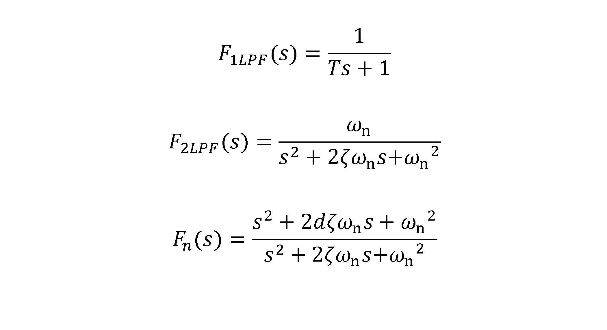
一次ローパスフォルタ、二次ローパスフィルタ及びノッチフィルタで構成されるフィルタの周波数特性(ゲイン特性及び位相特性)は、数式7(以下の数7)のF1(jω)、F2(jω)及びF3(jω)をF1LPF(jω)、F2LPF(jω)及びFn(jω)に置き替えることで求められる。
図15に示す表示画面の表示領域110Cにフィルタの周波数特性が表示される。
図15に示す表示画面の表示領域110Cにフィルタの周波数特性が表示される。
以上説明した各実施形態の出力装置100に含まれる構成部は、ハードウェア、ソフトウェア又はこれらの組み合わせにより実現することができる。ここで、ソフトウェアによって実現されるとは、コンピュータがプログラムを読み込んで実行することにより実現されることを意味する。
出力装置100に含まれる構成部をソフトウェア又はこれらの組み合わせにより実現する実現するために、出力装置100は、CPU(Central Processing Unit)等の演算処理装置を備える。演算処理装置は実行部として機能する。また、出力装置100は、アプリケーションソフトウェア又はOS(Operating System)等の各種の制御用プログラムを格納したHDD(Hard Disk Drive)等の補助記憶装置、及び演算処理装置がプログラムを実行する上で一時的に必要とされるデータを格納するためのRAM(Random Access Memory)といった主記憶装置も備える。
出力装置100に含まれる構成部をソフトウェア又はこれらの組み合わせにより実現する実現するために、出力装置100は、CPU(Central Processing Unit)等の演算処理装置を備える。演算処理装置は実行部として機能する。また、出力装置100は、アプリケーションソフトウェア又はOS(Operating System)等の各種の制御用プログラムを格納したHDD(Hard Disk Drive)等の補助記憶装置、及び演算処理装置がプログラムを実行する上で一時的に必要とされるデータを格納するためのRAM(Random Access Memory)といった主記憶装置も備える。
そして、出力装置100は、演算処理装置が補助記憶装置からアプリケーションソフトウェア又はOSを読み込み、読み込んだアプリケーションソフトウェア又はOSを主記憶装置に展開させながら、これらのアプリケーションソフトウェア又はOSに基づいた演算処理を行なう。また、この演算結果に基づいて、出力装置100が備える各種のハードウェアを制御する。これにより、本実施形態の機能ブロックは実現される。
出力装置100に含まれる構成部は、電子回路等を含むハードウェアにより実現することができる。出力装置100をハードウェアで構成する場合、出力装置100に含まれる各構成部の機能の一部又は全部を、例えば、ASIC(Application Specific Integrated Circuit)、ゲートアレイ、FPGA(Field Programmable Gate Array)、CPLD(Complex Programmable Logic Device)等の集積回路(IC)で構成することができる。
プログラムは、様々なタイプの非一時的なコンピュータ可読媒体(non-transitory computer readable medium)を用いて格納され、コンピュータに供給することができる。非一時的なコンピュータ可読媒体は、様々なタイプの実体のある記録媒体(tangible storage medium)を含む。非一時的なコンピュータ可読媒体の例は、磁気記録媒体(例えば、ハードディスクドライブ)、光磁気記録媒体(例えば、光磁気ディスク)、CD-ROM(Read Only Memory)、CD-R、CD-R/W、半導体メモリ(例えば、マスクROM、PROM(Programmable ROM)、EPROM(Erasable PROM)、フラッシュROM、RAM(random access memory))を含む。また、プログラムは、様々なタイプの一時的なコンピュータ可読媒体(transitory computer readable medium)によってコンピュータに供給されてもよい。
以上説明した実施形態及び変形例の効果は、サーボ制御装置のゲイン又はフィルタ等のパラメータの調整によって、サーボ制御装置の系全体の特性及び評価指標がどのように変化するかをシミュレーションで求めることができることである。
以上、本開示について説明したが、本開示は上述した個々の実施形態及び変形例に限定されるものではない。これらの実施形態及び変形例は本開示の要旨を逸脱しない範囲で、又は特許請求の範囲に記載された内容とその均等物から導き出される本開示の要旨を逸脱しない範囲で、種々の追加、置き替え、変更、部分的削除等が可能である。
また、これらの実施形態及び変形例は、組み合わせて実施することもできる。例えば、上述した実施形態において、各動作の順序や各処理の順序は、一例として示したものであり、これらに限定されるものではない。
また、これらの実施形態及び変形例は、組み合わせて実施することもできる。例えば、上述した実施形態において、各動作の順序や各処理の順序は、一例として示したものであり、これらに限定されるものではない。
上記実施形態及び変形例に関し、さらに以下の付記を開示する。
(付記1)
工作機械、ロボット又は産業機械の軸を駆動するモータを制御するサーボ制御装置に対して設けられる出力装置(100)であって、
調整前の前記サーボ制御装置の系全体の周波数特性を保存する周波数特性保存部(103)と、
調整前の制御パラメータを記憶するパラメータ記憶部(104)と、
調整前の前記サーボ制御装置の系全体の周波数特性と、調整前の前記制御パラメータとを用いて、前記制御パラメータを調整するパラメータ調整部(106)と、
調整した前記制御パラメータを用いて、調整中の前記サーボ制御装置の系全体の周波数特性を計算する周波数特性計算部(107)と、
前記調整中の前記サーボ制御装置の系全体の周波数特性を評価する指標を計算する評価指標計算部(108)と、
前記調整中の、前記サーボ制御装置の系全体の周波数特性と前記評価指標を出力する出力部(109)と、
を備えた出力装置。
(付記1)
工作機械、ロボット又は産業機械の軸を駆動するモータを制御するサーボ制御装置に対して設けられる出力装置(100)であって、
調整前の前記サーボ制御装置の系全体の周波数特性を保存する周波数特性保存部(103)と、
調整前の制御パラメータを記憶するパラメータ記憶部(104)と、
調整前の前記サーボ制御装置の系全体の周波数特性と、調整前の前記制御パラメータとを用いて、前記制御パラメータを調整するパラメータ調整部(106)と、
調整した前記制御パラメータを用いて、調整中の前記サーボ制御装置の系全体の周波数特性を計算する周波数特性計算部(107)と、
前記調整中の前記サーボ制御装置の系全体の周波数特性を評価する指標を計算する評価指標計算部(108)と、
前記調整中の、前記サーボ制御装置の系全体の周波数特性と前記評価指標を出力する出力部(109)と、
を備えた出力装置。
(付記2)
前記周波数特性計算部(107)は、調整した前記制御パラメータを用いて前記サーボ制御装置に含まれるフィルタの周波数特性を計算し、
前記出力部(109)は、前記フィルタの周波数特性を出力する、付記1に記載の出力装置。
前記周波数特性計算部(107)は、調整した前記制御パラメータを用いて前記サーボ制御装置に含まれるフィルタの周波数特性を計算し、
前記出力部(109)は、前記フィルタの周波数特性を出力する、付記1に記載の出力装置。
(付記3)
前記出力部(109)は、調整中の複数の前記周波数特性と、複数の前記周波数特性をそれぞれ評価する複数の評価指標を、表示画面に、並べて若しくは重ねて表示、又は動画で表示する表示部(1092)を含む、付記1又は2に記載の出力装置。
前記出力部(109)は、調整中の複数の前記周波数特性と、複数の前記周波数特性をそれぞれ評価する複数の評価指標を、表示画面に、並べて若しくは重ねて表示、又は動画で表示する表示部(1092)を含む、付記1又は2に記載の出力装置。
(付記4)
前記出力部は、調整中の複数の前記周波数特性の推移を、前記表示画面に重ねた図又は動画を作成する作図部(1091)を備え、前記表示部(1092)は、前記作図部が作成した前記図又は動画を表示する、付記3に記載の出力装置。
前記出力部は、調整中の複数の前記周波数特性の推移を、前記表示画面に重ねた図又は動画を作成する作図部(1091)を備え、前記表示部(1092)は、前記作図部が作成した前記図又は動画を表示する、付記3に記載の出力装置。
(付記5)
前記パラメータ調整部(106)は、前記制御パラメータの調整を繰り返して前記前記制御パラメータの最適値を求める機械学習装置(400)である、付記1から4のいずれか1項に記載の出力装置。
前記パラメータ調整部(106)は、前記制御パラメータの調整を繰り返して前記前記制御パラメータの最適値を求める機械学習装置(400)である、付記1から4のいずれか1項に記載の出力装置。
(付記6)
調整前の前記サーボ制御装置の系全体の周波数特性を測定する周波数特性測定装置(300)を備えた、付記1から5のいずれかに記載の出力装置。
調整前の前記サーボ制御装置の系全体の周波数特性を測定する周波数特性測定装置(300)を備えた、付記1から5のいずれかに記載の出力装置。
(付記7)
付記1から6のいずれかに記載の出力装置(100)と、
工作機械、ロボット又は産業機械の軸を駆動するモータを制御するサーボ制御装置(200)と、
調整前の前記サーボ制御装置の系全体の周波数特性を測定する周波数特性測定装置(300)と、
を備えた出力システム。
付記1から6のいずれかに記載の出力装置(100)と、
工作機械、ロボット又は産業機械の軸を駆動するモータを制御するサーボ制御装置(200)と、
調整前の前記サーボ制御装置の系全体の周波数特性を測定する周波数特性測定装置(300)と、
を備えた出力システム。
(付記8)
工作機械、ロボット又は産業機械の軸を駆動するモータを制御するサーボ制御装置(200)に対して設けられる出力装置としてのコンピュータが、
調整前の前記サーボ制御装置の系全体の周波数特性を保存する処理と、
調整前の前記サーボ制御装置の系全体の周波数特性と、調整前の前記前記サーボ制御装置の制御パラメータとを用いて、前記制御パラメータを調整する処理と、
調整した前記制御パラメータを用いて、調整中の前記サーボ制御装置の系全体の周波数特性を計算する処理と、
前記調整中の前記サーボ制御装置の系全体の周波数特性を評価する指標を計算する処理と、
前記調整中の、前記サーボ制御装置の系全体の周波数特性と前記評価指標を出力する処理と、
を実行する、出力方法。
工作機械、ロボット又は産業機械の軸を駆動するモータを制御するサーボ制御装置(200)に対して設けられる出力装置としてのコンピュータが、
調整前の前記サーボ制御装置の系全体の周波数特性を保存する処理と、
調整前の前記サーボ制御装置の系全体の周波数特性と、調整前の前記前記サーボ制御装置の制御パラメータとを用いて、前記制御パラメータを調整する処理と、
調整した前記制御パラメータを用いて、調整中の前記サーボ制御装置の系全体の周波数特性を計算する処理と、
前記調整中の前記サーボ制御装置の系全体の周波数特性を評価する指標を計算する処理と、
前記調整中の、前記サーボ制御装置の系全体の周波数特性と前記評価指標を出力する処理と、
を実行する、出力方法。
10 出力システム
100 出力装置
101 情報取得部
102 情報出力部
103 周波数特性保存部
104 パラメータ記憶部
105 制御部
106 パラメータ調整部
107 周波数特性計算部
108 評価指標計算部
109 出力部
110 表示画面
200 サーボ制御装置
201 減算器
202 制御器
203 フィルタ
204 制御対象
300 周波数特性測定装置
400 機械学習装置
100 出力装置
101 情報取得部
102 情報出力部
103 周波数特性保存部
104 パラメータ記憶部
105 制御部
106 パラメータ調整部
107 周波数特性計算部
108 評価指標計算部
109 出力部
110 表示画面
200 サーボ制御装置
201 減算器
202 制御器
203 フィルタ
204 制御対象
300 周波数特性測定装置
400 機械学習装置
Claims (8)
- 工作機械、ロボット又は産業機械の軸を駆動するモータを制御するサーボ制御装置に対して設けられる出力装置であって、
調整前の前記サーボ制御装置の系全体の周波数特性を保存する周波数特性保存部と、
調整前の制御パラメータを記憶するパラメータ記憶部と、
調整前の前記サーボ制御装置の系全体の周波数特性と、調整前の前記制御パラメータとを用いて、前記制御パラメータを調整するパラメータ調整部と、
調整した前記制御パラメータを用いて、調整中の前記サーボ制御装置の系全体の周波数特性を計算する周波数特性計算部と、
前記調整中の前記サーボ制御装置の系全体の周波数特性を評価する指標を計算する評価指標計算部と、
前記調整中の、前記サーボ制御装置の系全体の周波数特性と前記評価指標を出力する出力部と、
を備えた出力装置。 - 前記周波数特性計算部は、調整した前記制御パラメータを用いて前記サーボ制御装置に含まれるフィルタの周波数特性を計算し、
前記出力部は、前記フィルタの周波数特性を出力する、請求項1に記載の出力装置。 - 前記出力部は、調整中の複数の前記周波数特性と、複数の前記周波数特性をそれぞれ評価する複数の評価指標とを、表示画面に、並べて若しくは重ねて表示、又は動画で表示する表示部を含む、請求項1又は2に記載の出力装置。
- 前記出力部は、調整中の複数の前記周波数特性の推移を、前記表示画面に重ねた図又は動画を作成する作図部を備え、前記表示部は、前記作図部が作成した前記図又は動画を表示する、請求項3に記載の出力装置。
- 前記パラメータ調整部は、前記制御パラメータの調整を繰り返して前記前記制御パラメータの最適値を求める機械学習装置である、請求項1から4のいずれか1項に記載の出力装置。
- 調整前の前記サーボ制御装置の系全体の周波数特性を測定する周波数特性測定装置を備えた、請求項1から5のいずれかに記載の出力装置。
- 請求項1から6のいずれかに記載の出力装置と、
工作機械、ロボット又は産業機械の軸を駆動するモータを制御するサーボ制御装置と、
調整前の前記サーボ制御装置の系全体の周波数特性を測定する周波数特性測定装置と、
を備えた出力システム。 - 工作機械、ロボット又は産業機械の軸を駆動するモータを制御するサーボ制御装置に対して設けられる出力装置としてのコンピュータが、
調整前の前記サーボ制御装置の系全体の周波数特性を保存する処理と、
調整前の前記サーボ制御装置の系全体の周波数特性と、調整前の前記前記サーボ制御装置の制御パラメータとを用いて、前記制御パラメータを調整する処理と、
調整した前記制御パラメータを用いて、調整中の前記サーボ制御装置の系全体の周波数特性を計算する処理と、
前記調整中の前記サーボ制御装置の系全体の周波数特性を評価する指標を計算する処理と、
前記調整中の、前記サーボ制御装置の系全体の周波数特性と前記評価指標を出力する処理と、
を実行する、出力方法。
Priority Applications (2)
| Application Number | Priority Date | Filing Date | Title |
|---|---|---|---|
| PCT/JP2023/009906 WO2024189786A1 (ja) | 2023-03-14 | 2023-03-14 | 出力装置、出力システム、及び出力方法 |
| JP2025506324A JPWO2024189786A1 (ja) | 2023-03-14 | 2023-03-14 |
Applications Claiming Priority (1)
| Application Number | Priority Date | Filing Date | Title |
|---|---|---|---|
| PCT/JP2023/009906 WO2024189786A1 (ja) | 2023-03-14 | 2023-03-14 | 出力装置、出力システム、及び出力方法 |
Publications (1)
| Publication Number | Publication Date |
|---|---|
| WO2024189786A1 true WO2024189786A1 (ja) | 2024-09-19 |
Family
ID=92754721
Family Applications (1)
| Application Number | Title | Priority Date | Filing Date |
|---|---|---|---|
| PCT/JP2023/009906 Ceased WO2024189786A1 (ja) | 2023-03-14 | 2023-03-14 | 出力装置、出力システム、及び出力方法 |
Country Status (2)
| Country | Link |
|---|---|
| JP (1) | JPWO2024189786A1 (ja) |
| WO (1) | WO2024189786A1 (ja) |
Cited By (1)
| Publication number | Priority date | Publication date | Assignee | Title |
|---|---|---|---|---|
| CN121055846A (zh) * | 2025-10-31 | 2025-12-02 | 河北工程大学 | 一种电动机动态效率优化调控系统 |
Citations (3)
| Publication number | Priority date | Publication date | Assignee | Title |
|---|---|---|---|---|
| JP2006277652A (ja) * | 2005-03-30 | 2006-10-12 | Tokyo Univ Of Agriculture & Technology | サーボゲイン算出方法、サーボゲイン算出プログラム及びサーボゲイン算出装置 |
| JP2007072898A (ja) * | 2005-09-08 | 2007-03-22 | Sony Corp | サーボ制御装置及び制御パラメータ決定方法、並びに制御パラメータ決定プログラム |
| WO2023032175A1 (ja) * | 2021-09-03 | 2023-03-09 | ファナック株式会社 | 周波数特性予測装置及び周波数特性予測方法 |
-
2023
- 2023-03-14 WO PCT/JP2023/009906 patent/WO2024189786A1/ja not_active Ceased
- 2023-03-14 JP JP2025506324A patent/JPWO2024189786A1/ja active Pending
Patent Citations (3)
| Publication number | Priority date | Publication date | Assignee | Title |
|---|---|---|---|---|
| JP2006277652A (ja) * | 2005-03-30 | 2006-10-12 | Tokyo Univ Of Agriculture & Technology | サーボゲイン算出方法、サーボゲイン算出プログラム及びサーボゲイン算出装置 |
| JP2007072898A (ja) * | 2005-09-08 | 2007-03-22 | Sony Corp | サーボ制御装置及び制御パラメータ決定方法、並びに制御パラメータ決定プログラム |
| WO2023032175A1 (ja) * | 2021-09-03 | 2023-03-09 | ファナック株式会社 | 周波数特性予測装置及び周波数特性予測方法 |
Cited By (1)
| Publication number | Priority date | Publication date | Assignee | Title |
|---|---|---|---|---|
| CN121055846A (zh) * | 2025-10-31 | 2025-12-02 | 河北工程大学 | 一种电动机动态效率优化调控系统 |
Also Published As
| Publication number | Publication date |
|---|---|
| JPWO2024189786A1 (ja) | 2024-09-19 |
Similar Documents
| Publication | Publication Date | Title |
|---|---|---|
| JP6860540B2 (ja) | 出力装置、制御装置、及び学習パラメータの出力方法 | |
| JP6901450B2 (ja) | 機械学習装置、制御装置及び機械学習方法 | |
| CN110658785B (zh) | 输出装置、控制装置、以及评价函数值的输出方法 | |
| JP7022261B1 (ja) | 周波数特性予測装置及び周波数特性予測方法 | |
| JP7381751B2 (ja) | 制御支援装置、制御装置及び制御支援方法 | |
| US20200150599A1 (en) | Output device, control device, and method for outputting evaluation functions and machine learning results | |
| JP7000373B2 (ja) | 機械学習装置、制御装置及び機械学習方法 | |
| CN111722530B (zh) | 机器学习装置、控制系统以及机器学习方法 | |
| JP6978452B2 (ja) | 機械学習装置、制御装置、及び機械学習の探索範囲の設定方法 | |
| JP6956122B2 (ja) | フィルタの係数を最適化する機械学習システム、制御装置及び機械学習方法 | |
| CN110875703B (zh) | 机器学习装置、控制系统以及机器学习方法 | |
| JP7469476B2 (ja) | 制御支援装置、制御システム及び制御支援方法 | |
| WO2024189786A1 (ja) | 出力装置、出力システム、及び出力方法 | |
| JP7769100B2 (ja) | 制御パラメータを調整する調整装置、制御システム及び制御パラメータ調整方法 | |
| JP7586920B2 (ja) | 制御支援装置、制御システム及びフィルタ調整支援方法 | |
| JP6740290B2 (ja) | 機械学習装置、制御装置、及び機械学習方法 | |
| JP7509866B2 (ja) | 機械学習装置、制御装置及び機械学習方法 | |
| JP7741190B2 (ja) | 安定余裕の設定支援装置、制御システム及び設定支援方法 |
Legal Events
| Date | Code | Title | Description |
|---|---|---|---|
| 121 | Ep: the epo has been informed by wipo that ep was designated in this application |
Ref document number: 23927407 Country of ref document: EP Kind code of ref document: A1 |
|
| WWE | Wipo information: entry into national phase |
Ref document number: 2025506324 Country of ref document: JP |
|
| NENP | Non-entry into the national phase |
Ref country code: DE |
|
| 122 | Ep: pct application non-entry in european phase |
Ref document number: 23927407 Country of ref document: EP Kind code of ref document: A1 |