WO2024189744A1 - 無人飛行体誘導システム、無人飛行体誘導装置、無人飛行体誘導方法および無人飛行体誘導用プログラム - Google Patents
無人飛行体誘導システム、無人飛行体誘導装置、無人飛行体誘導方法および無人飛行体誘導用プログラム Download PDFInfo
- Publication number
- WO2024189744A1 WO2024189744A1 PCT/JP2023/009672 JP2023009672W WO2024189744A1 WO 2024189744 A1 WO2024189744 A1 WO 2024189744A1 JP 2023009672 W JP2023009672 W JP 2023009672W WO 2024189744 A1 WO2024189744 A1 WO 2024189744A1
- Authority
- WO
- WIPO (PCT)
- Prior art keywords
- marker
- aerial vehicle
- unmanned aerial
- guidance
- markers
- Prior art date
- Legal status (The legal status is an assumption and is not a legal conclusion. Google has not performed a legal analysis and makes no representation as to the accuracy of the status listed.)
- Ceased
Links
Images





Classifications
-
- B—PERFORMING OPERATIONS; TRANSPORTING
- B64—AIRCRAFT; AVIATION; COSMONAUTICS
- B64C—AEROPLANES; HELICOPTERS
- B64C13/00—Control systems or transmitting systems for actuating flying-control surfaces, lift-increasing flaps, air brakes, or spoilers
- B64C13/02—Initiating means
- B64C13/16—Initiating means actuated automatically, e.g. responsive to gust detectors
- B64C13/18—Initiating means actuated automatically, e.g. responsive to gust detectors using automatic pilot
-
- B—PERFORMING OPERATIONS; TRANSPORTING
- B64—AIRCRAFT; AVIATION; COSMONAUTICS
- B64C—AEROPLANES; HELICOPTERS
- B64C39/00—Aircraft not otherwise provided for
- B64C39/02—Aircraft not otherwise provided for characterised by special use
-
- B—PERFORMING OPERATIONS; TRANSPORTING
- B64—AIRCRAFT; AVIATION; COSMONAUTICS
- B64D—EQUIPMENT FOR FITTING IN OR TO AIRCRAFT; FLIGHT SUITS; PARACHUTES; ARRANGEMENT OR MOUNTING OF POWER PLANTS OR PROPULSION TRANSMISSIONS IN AIRCRAFT
- B64D47/00—Equipment not otherwise provided for
- B64D47/02—Arrangements or adaptations of signal or lighting devices
-
- B—PERFORMING OPERATIONS; TRANSPORTING
- B64—AIRCRAFT; AVIATION; COSMONAUTICS
- B64U—UNMANNED AERIAL VEHICLES [UAV]; EQUIPMENT THEREFOR
- B64U10/00—Type of UAV
- B64U10/10—Rotorcrafts
Definitions
- This disclosure relates to an unmanned aerial vehicle guidance system, an unmanned aerial vehicle guidance device, an unmanned aerial vehicle guidance method, and an unmanned aerial vehicle guidance program, and in particular to an unmanned aerial vehicle guidance system, an unmanned aerial vehicle guidance device, an unmanned aerial vehicle guidance method, and an unmanned aerial vehicle guidance program that are suitable for moving an unmanned aerial vehicle flying in the air or on the ground by automatic driving without relying on the visual observation of a pilot.
- a known technology for autonomously moving an unmanned aerial vehicle (hereafter referred to as a "drone") in environments where GPS cannot be used, such as indoors or in spaces under ceilings, is to analyze camera footage to confirm visibility and proceed with the movement while checking that there are no obstructions.
- a known technology for autonomously moving an unmanned aerial vehicle hereafter referred to as a "drone” in environments where GPS cannot be used, such as indoors or in spaces under ceilings, is to analyze camera footage to confirm visibility and proceed with the movement while checking that there are no obstructions.
- Such technology is disclosed, for example, in Patent Document 1 below.
- the first objective of this disclosure is to provide an unmanned aerial vehicle guidance system that can move a drone by automatic control without relying on GPS, even in dark environments without lighting, in order to solve the above problems.
- a second objective of this disclosure is to provide an unmanned aerial vehicle guidance device that can move a drone by automatic control without relying on GPS, even in dark environments with no lighting.
- the third objective of this disclosure is to provide an unmanned aerial vehicle guidance method for moving a drone by automatic control without relying on GPS, even in dark environments without lighting.
- the fourth objective of this disclosure is to provide an unmanned aerial vehicle guidance program for moving a drone by automatic control without relying on GPS, even in dark environments without lighting.
- a first aspect is an unmanned aerial vehicle guidance system for moving an unmanned aerial vehicle along a guidance path, comprising: a plurality of markers arranged along the guide route, the markers transmitting wireless signals toward the guide route so that adjacent markers do not interfere with each other;
- the unmanned aerial vehicle is a steering and thrust system for moving the unmanned aerial vehicle in a desired direction; an antenna for receiving a wireless signal from the marker; a direct wave extracting unit that extracts a direct wave from the wireless signal received by the antenna from each of the markers;
- a guidance direction search unit that searches for a guidance direction of the unmanned aerial vehicle based on the direct wave; a drive control unit that controls the steering and thrust system so that the unmanned aerial vehicle moves in a direction indicated by a result of the search;
- the guidance direction search unit is a marker recognition process for recognizing some of the plurality of markers as level measurement markers based on a reception level of the direct wave; A process of recognizing a marker disposed adjacent to the level measurement marker in the traveling direction as a direction marker
- a second aspect is an unmanned aerial vehicle guidance device for moving an unmanned aerial vehicle along a guidance path, comprising: a steering and thrust system for moving the unmanned aerial vehicle in a desired direction; an antenna that receives wireless signals from a plurality of markers that are arranged along the guide route and transmit wireless signals toward the guide route so that adjacent markers do not interfere with each other; a direct wave extracting unit that extracts a direct wave from the wireless signal received by the antenna from each of the markers; A guidance direction search unit that searches for a guidance direction of the unmanned aerial vehicle based on the direct wave; a drive control unit that controls the steering and thrust system so that the unmanned aerial vehicle moves in a direction indicated by a result of the search;
- the guidance direction search unit is a marker recognition process for recognizing a part of the plurality of markers as a level measurement marker based on a reception level of the direct wave; A process of recognizing a marker disposed adjacent to the level measurement marker in the traveling direction as a direction marker; a direction search process for searching, as the guidance direction
- a third aspect is an unmanned aerial vehicle guidance method for moving an unmanned aerial vehicle along a guidance path, comprising: arranging a plurality of markers along the guide route, the markers transmitting wireless signals toward the guide route such that adjacent markers do not interfere with each other; moving the unmanned aerial vehicle in a desired direction using a steering and thrust system; An antenna mounted on the unmanned aerial vehicle receives a wireless signal from the marker; extracting a direct wave from a radio signal received by said antenna from each of said markers; Searching for a guidance direction of the unmanned aerial vehicle based on the direct wave; and controlling the steering and thrust system so that the unmanned aerial vehicle moves in a direction indicated by the results of the search;
- the searching of the guidance direction includes: recognizing a part of the plurality of markers as a level measurement marker based on a reception level of the direct wave; Recognizing a marker disposed adjacent to the level measurement marker in the traveling direction as a direction marker; It is desirable to include searching for the guidance direction to be a direction in which it can be determined that the un
- a fourth aspect is a program for guiding an unmanned aerial vehicle, in an environment in which a plurality of markers, which transmit radio signals toward a guided route so that adjacent markers do not interfere with each other, are arranged along the guided route, for moving the unmanned aerial vehicle along the guided route, comprising:
- the unmanned aerial vehicle is a steering and thrust system for moving the unmanned aerial vehicle in a desired direction; an antenna for receiving a wireless signal from the marker; a processor;
- the processor extracting a direct wave from the radio signals received by the antenna from each of the markers; A process of searching for a guidance direction of the unmanned aerial vehicle based on the direct wave; and controlling the steering and thrust system so that the unmanned aerial vehicle moves in a direction indicated by the search results.
- the process of searching for a guidance direction includes: a process of recognizing some of the plurality of markers as level measurement markers based on a reception level of the direct wave; A process of recognizing a marker disposed adjacent to the level measurement marker in the traveling direction as a direction marker; It is desirable to include a process of searching for the guidance direction to be a direction in which it can be determined that the unmanned aerial vehicle will be on the guidance path based on the direct wave from the level measurement marker, and in which it can be determined that the unmanned aerial vehicle will approach the direction marker based on the direct wave from the direction marker.
- the drone can be automatically controlled to move along a desired guided path even in a dark environment without lighting.
- FIG. 1 is a block diagram for explaining various functions installed in a drone in embodiment 1 of the present disclosure.
- FIG. 4 is a diagram for functionally explaining the configuration of the direct wave extraction unit shown in FIG. 3 .
- FIG. 1 is a diagram for explaining guidance logic for moving a drone along a guidance path. 4 is a flowchart (part 1) for explaining the flow of a series of processes executed by a guidance direction searching unit shown in FIG. 3 to search for a traveling direction.
- FIG. 4 is a flowchart (part 2) for explaining the flow of a series of processes executed by the guidance direction searching unit shown in FIG. 3 to search for a traveling direction.
- 10 is a flowchart (part 3) for explaining the flow of a series of processes executed by the guidance direction searching unit shown in FIG. 3 to search for a traveling direction.
- FIG. 1 is a diagram for explaining an outline of an unmanned aerial vehicle guidance system according to a first embodiment of the present disclosure.
- the system shown in Fig. 1 is installed in an indoor space 10.
- the indoor space 10 is surrounded by a floor, side walls, and a ceiling. It is assumed that it is difficult to acquire a GPS signal in the indoor space 10.
- markers 14-1 to 14-8 are installed along the guide path 12.
- Markers 14-1 and 14-2 are installed facing each other on both sides of the guide path 12.
- Markers 14-3 and 14-4, markers 14-5 and markers 14-6, and even markers 14-7 and markers 14-8 also face each other on both sides of the guide path 12.
- marker pair 14-i, (i+1) when it is not necessary to distinguish between individual markers, the suffix of the reference number will be omitted and they will be referred to as "marker 14".
- Each of the markers 14 transmits a radio signal in the direction of the guided route 12.
- the output power P and frequency f (wavelength ⁇ ) of the radio signal are set individually for each marker 14. Therefore, it is possible to identify whether any of the radio signals flying around the indoor space 10 originated from a marker 14 based on the frequency f or wavelength ⁇ .
- the update boundary 16-1 is a boundary where the relationship between the wireless signal level from the marker pair 14-1, 2 and the threshold value ThL, and the relationship between the wireless signal level from the marker pair 14-3, 4 and the threshold value ThD switch.
- the update boundary 16-2 is a boundary where the relationship between the signal level from the marker pair 14-3, 4 and the signal level from the marker pair 14-5, 6 and the associated threshold values ThL and ThD switch. Note that while only two update boundaries are illustrated in FIG. 1, the same type of update boundary will inevitably occur between adjacent marker pairs.
- reference numeral 18-1 indicates an unmanned aerial vehicle (drone) that exists in a zone in the indoor space 10 where the reception level from the marker pair 14-1, 2 is strong.
- Reference numeral 18-2 indicates a drone that has crossed the update boundary 16-1 and moved into a zone where the reception level from the marker pair 14-3, 4 is strong.
- Reference numeral 18-3 indicates a drone that has crossed the next update boundary 16-2 and moved into a zone where the reception level from the marker pair 14-5, 6 is strong.
- the subscript will be omitted and the drone will be given the reference numeral "18.”
- the drone 18 follows the signal from the marker 14 and moves along the guided path 12 in the indoor space 10 by autonomous driving without relying on GPS.
- the features that realize this function are described in detail below.
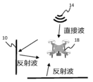
- [Direct wave extraction] 2 is a diagram for explaining how a wireless signal from the marker 14 propagates through the indoor space 10.
- the wireless signal from the marker 14 reaches the drone 18 as a direct wave, and also as a reflected wave generated by reflection on the floor, wall, ceiling, etc.
- the reflected wave reaches the drone 18 from a direction different from the direction in which the marker 14 exists.
- the reception level of the direct wave depends on the distance to the marker 14, but the reception level of the reflected wave is affected by the order of reflection and the state of the reflecting surface in addition to the distance.
- the drone 18 is made to extract only direct waves from the radio signal from the marker 14 and determine its course based on these direct waves.
- FIG. 3 is a block diagram for explaining various functions installed in the drone 18 in this embodiment. As shown in FIG. 3, the drone 18 is equipped with an antenna 20. The drone 18 receives a wireless signal from the marker 14 via the antenna 20.
- the antenna 20 converts the received radio signal into an electrical signal and provides it to the direct wave extraction unit 22.
- the direct wave extraction unit 22 has the function of extracting only the direct wave component from a signal that contains a mixture of direct wave components and reflected wave components.
- the direct wave components extracted by the direct wave extraction unit 22 are provided to the guidance direction search unit 24.
- the guidance direction search unit 24 analyzes the direct waves and searches for a direction of travel for moving the drone 18 along the guidance path 12.
- the results of the search by the guidance direction search unit 24 are provided to the drive control unit 26.
- the drive control unit 26 is a block for controlling the steering and thrust system 28 mounted on the drone 18.
- the steering and thrust system 28 is controlled by the drive control unit 26, causing the drone 18 to move in a direction that follows the search results of the guidance direction search unit 24.
- the above-mentioned direct wave extraction unit 22, guidance direction search unit 24, and drive control unit 26 are each realized by combining dedicated hardware and a computer system.
- the computer system includes a processor such as a CPU, and a memory device that stores a program to be executed by the processor.
- the functions of the direct wave extraction unit 22, etc. are realized by having the processor execute the program stored in the memory device.
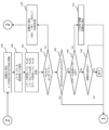
- FIG. 4 shows a diagram for functionally explaining the configuration of the direct wave extraction unit 22.
- the "input yi(t)" shown in the lower left of FIG. 4 is an electrical signal provided to the direct wave extraction unit 22 from the antenna 20, that is, an input signal that contains a mixture of direct wave components and reflected wave components.
- the input yi(t) is provided to the delay profile measurement device 30 as shown in the figure.
- the delay profile measurement device 30 analyzes the input yi(t) to measure the delay profile contained in the radio signal received by the antenna 20.
- the delay profile is the impulse response at time t, and the elements corresponding to the delay time ⁇ can be expressed as h(t, ⁇ ). If the complex amplitude of the transmission wave from the marker 14 at time t is x(t), then the input yi(t), that is, the complex amplitude yi(t) of the radio signal received by the antenna 20, can be expressed as follows:
- Equation (3) indicates that the output yo(t, ⁇ k ) is the amplitude of an element with a delay time of ⁇ k .
- the direct wave component is the component when the delay time ⁇ is zero. Therefore, the direct wave can be extracted by multiplying the input yi(t) by the complex conjugate h * (t,0) of the corresponding impulse response h(t,0) and integrating it. This relationship can be expressed as follows.
- the measurement result of the delay profile measurement device 30 is provided to a complex conjugate generator 32.
- the complex conjugate generator 32 generates a complex conjugate h * (t,0) when the delay time ⁇ is zero, based on the profile measured by the delay profile measurement device 30.
- the conjugate complex number h * (t,0) generated by the conjugate complex number generator 32 is provided to a multiplier 34 together with an input yi(t) from the antenna 20.
- the result of the multiplier 34 is provided to an integrator 36.
- the multiplier 34 and the integrator 36 perform the calculation of the above equation (4).
- an output yo(t, ⁇ k ) representing an element with a delay time ⁇ of zero, i.e., a direct wave from the marker 14, is extracted from the integrator 36.
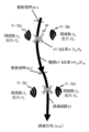
- [Drone Guidance Logic] 5 is a diagram for explaining the guidance logic for moving the drone 18 along the guidance path 12.
- a plurality of marker pairs 14-i, (i+1) are arranged adjacent to each other along the guidance path 12.
- a frequency f that does not interfere with each other is set for all of the marker pairs 14-i, (i+1).
- the frequency f, output P, and position (x, y) of each of the marker pairs 14-i, (i+1) are registered in advance in the guidance direction search unit 24 of the drone 18.
- the marker pair 14-i, (i+1) arranged along the guidance path 12 functions as a level measurement marker pair A, B (hereinafter referred to as "L marker pair A, B") or a direction marker pair C, D (hereinafter referred to as "D marker pair C, D”) in relation to the location of the drone 18.
- the drone 18 recognizes the closest marker pair 14-i, (i+1) as the L marker pair A, B. Then, it searches for its own traveling direction so that the reception level ratio P A /P B from the L marker pair A, B falls within a desired range.
- the drone 18 recognizes the marker pair 14-i, (i+1) adjacent to the L marker pair A, B in the traveling direction as the D marker pair C, D, and searches for its own traveling direction so as to approach the D marker pair C, D.
- the drone 18 moving in front of the update boundary 16-2 passes the update boundary 16-2, the closest marker pair 14-i, (i+1) changes from the previous L marker pair A, B to the previous D marker pair C, D.
- the drone 18 updates the L marker pair A, B and the D marker pair C, D to the next marker pair 14-i, (i+1), respectively.
- the drone 18 searches for its own traveling direction so that the reception level ratio P A /P B from the updated L marker pair A, B falls within the desired range and approaches the updated D marker pair C, D.
- the drone 18 of this embodiment repeats the above process to realize movement along the guidance route 12 without relying on GPS.
- the drone 18 of this embodiment extracts a direct wave from the marker 14. Then, the drone 18 searches for its own traveling direction so that the reception level ratio P A /P B from the L marker pair A, B falls within a desired range. If P A and P B have the same value, the reception level ratio P A /P B will be "1". If the drone 18 is located at the midpoint of the L marker pair A, B, P A and P B will be approximately the same value. Therefore, if the "desired range" is determined to be, for example, 0.9 ⁇ P A /P B ⁇ 1.1, the drone 18 can be flown so as to trace approximately the midpoint of the sequentially updated L marker pair A, B.
- each of the multiple markers 14 is made to transmit a radio signal with a different frequency f.
- radio waves have the property that they attenuate in proportion to the square of the distance in free space and inversely proportional to the square of the wavelength. Therefore, if the frequency is different, there will be a difference in the reception level of the radio signal even if the distance to the marker 14 is the same.
- the marker pair 14-3, 14-4 is disposed at a corner portion of the guided route 12.
- the coordinates (x0, y0) on the guided route 12 are not equidistant from both of the marker pair 14-3, 14-4. Therefore, if the reception level ratio P A /P B is always kept within a certain range, for example, 0.9 ⁇ P A /P B ⁇ 1.1, the drone 18 cannot be flown along the desired guided route 12.
- the reception level P rA of the signal that will be received from L marker A of frequency f A and the reception level P rB of the signal that will be received from L marker B of frequency f B are estimated.
- these are referred to as the “ideal level P rA” and the “ideal level P rB ".
- the ratio between them is referred to as the “ideal level ratio P rA /P rB ".
- the above-mentioned ideal level ratio P rA /P rB is used as the basis of the "desired range" that the reception level ratio P A /P B should satisfy.
- the installation position ( xA , yA ) of the L marker A and the frequency fA (wavelength ⁇ A ) used by the L marker A are known to the drone 18. Therefore, once the coordinates (x0, y0) to be guided are determined, the ideal level P rA at the coordinates (x0, y0) can be calculated.
- the following formula is the ideal level P rA expressed using the wavelength ⁇ A .
- the ideal level P rB from the other L marker B that forms a pair with the L marker A can be expressed as follows using the position (x B , y B ) and wavelength ⁇ B :
- the ideal level ratio P rA /P rB can be expressed as follows: In the following formula (7), however, the wavelengths ⁇ A and ⁇ B are replaced with frequencies f A and f B.
- K is a value that varies depending on the relative position between the coordinates (x0, y0) of the position to be guided and the coordinates ( xA , yA ), ( xB , yB ) of the L marker pair A, B.
- (P A /P B ) ⁇ ( fB 2 / fA 2 ) is a value determined for each marker pair 14-i, (i+1).
- (P A /P B ) ⁇ ( fB 2 / fA 2 ) is approximately "1" for all marker pairs 14-i, (i+1).
- the drone 18 searches for its own traveling direction so that the reception level ratio P A /P B from the L marker pair A, B is equal to or greater than "X% of K" and equal to or less than "Y% of K.”
- the drone 18 searches for its own traveling method so that the reception levels P C , P D from the D marker pair C, D become large.
- the drone 18 can be moved along the desired guide route 12 by automatic driving without relying on GPS.
- FIGS. 6 to 8 are flowcharts for explaining the flow of a series of processing executed by the guidance direction search unit 24 to search for a traveling direction.
- drone 18 When drone 18 starts autonomous driving, it knows the positions (x, y) of all markers 14 installed on the guided path 12, as well as the power P and frequency f (wavelength ⁇ ) set for those markers 14. It is also assumed that drone 18 knows which markers 14 should be recognized as the initial L marker and D marker.
- the drone 18 first moves a certain distance in the X direction determined by a function such as a gyro, and stores the coordinates of the destination as a position (M) (step 100).
- reception levels P A and P B from the L marker pair A, B and their ratio P A /P B , as well as the reception levels P C and P D from the D marker pair C, D are stored (step 104 ).
- the former threshold ThL is a threshold for determining whether the reception levels P A , P B of the L marker pair A, B have dropped to a value at which the L marker pair A, B should be updated.
- the latter threshold ThD is a threshold for determining whether the reception levels P C , P D of the marker 14 recognized as the D marker pair C, D have increased to a degree that they can be used as the L marker pair A, B. It is assumed that the determination in this step 106 is satisfied when the drone 18 has crossed the update boundary 16 due to the movement in the above step 100.
- step 106 if it is determined that P A , P B ⁇ ThL and P C , P D ⁇ ThD, it can be determined that the drone 18 has crossed the update boundary 16. In this case, the previous D marker pair C, D is changed to a new L marker pair A, B. In addition, an update is performed in which the marker pair 14-i, (i+1) installed adjacent to the previous D marker pair C, D is set as the new D marker pair C, D (step 108). After that, the processing from step 102 onwards is repeated again.
- step 106 if it is not found that P A , P B ⁇ ThL and P C , P D ⁇ ThD, it can be determined that there is a possibility that the current X direction is not along the guide route 12.
- step 110 it is determined whether or not the reception level ratio P A /P B of the L markers A and B approaches "K" in the above formula (7) from the previous value (step 110).
- step 110 specifically, first, the coordinates (x, y) of the position (M) are estimated based on the reception levels P A , P B or based on the past trajectory of the vehicle itself.
- the coordinates (x0, y0) of the position to be guided on the guide route 12 are determined based on the coordinates (x, y). Then, "K” in the above formula (7) is calculated based on the coordinates (x0, y0). Finally, it is determined whether or not the current reception level ratio P A /P B approaches "K" from the previous value or from the initial setting value.
- reception level ratio P A /P B approaches "K"
- the above X and Y can be set to any value as long as they satisfy the relationship X ⁇ Y.
- the guidance position (x, y) can be set close to the midpoint between the L marker pair A and B. By adjusting these values appropriately, it is possible to bring the guidance position (x, y) closer to one L marker A or the other L marker B.
- step 112 if the relationship "X% of K ⁇ PA / PB ⁇ Y% of K" is not established, it can be determined that the drone 18 is approaching the guided path 12 but has not yet entered the guided path 12. In this case, the current X direction is stored (maintained) as the X direction (step 114), and the processing from step 100 onwards is repeated again.
- step 112 it can be determined that the drone 18 is moving along the guidance path 12. In this case, it is then determined whether or not the reception levels P C and P D of the D marker pair C and D have increased from the previous routine to the current routine, or compared to the initial setting value (step 116).
- step 114 If it is determined that position (M) is not the end point, the process goes through step 114 and repeats the process from step 100 onwards to continue the movement of the drone 18. On the other hand, if it is determined that position (M) is the end point, the current routine is terminated.
- step 116 if no increase in the reception levels P C and P D of the D marker pair C and D is recognized in step 116, it can be determined that the drone 18 is located on the guidance path 12, but the direction of travel may be incorrect. In this case, it moves in the ⁇ X direction and returns to the previous position (M), that is, the position (M) before the movement in step 100 (step 120).
- step 114 the "-X" direction is stored as the new "X" direction. Then, the processing from step 100 onwards is repeated for the new X direction.
- step 110 if it is determined in step 110 that the reception level ratio P A /P B of the L marker pair A, B is not approaching "K”, it can be determined that the drone 18 cannot approach the guidance path 12 in the current X direction. In this case, the series of processes shown in Fig. 7 are executed thereafter.
- the process returns to the previous position (M) and sets the Y direction, which has an angle of 90° with respect to the current X direction, as the movement direction (step 122). Also, as in step 100 above, the position moved a certain distance in the Y direction is stored as the new (M).
- steps 124 and 126 are substantially similar to the processes of steps 102 and 104 shown in Fig. 6. Through these processes, the reception levels P A and P B , the reception level ratio P A /P B , and the reception levels P C and P D at the position (M) moved in the Y direction are stored.
- steps 128 to 136 is substantially the same as the processing of steps 110 to 112 and steps 116 to 120 shown in Fig. 6. If the reception level ratio P A /P B approaches K (step 128), "X% of K ⁇ P A /P B ⁇ Y% of K" is established (step 130), and the reception levels P C and P D of the D marker pair C and D are increasing (step 132), it is determined that the movement direction is appropriate. Then, if the movement destination is the end point, the current processing is terminated (step 134).
- step 130 determines whether "X% of K ⁇ PA / PB ⁇ Y% of K" holds. If it is not determined in step 130 that "X% of K ⁇ PA / PB ⁇ Y% of K" holds, it can be determined that the drone 18 is approaching the guided path 12 but has not yet entered the guided path 12. In this case, the current Y direction is re-stored as the X direction (step 114), and the processes from step 100 onwards are repeated again.
- step 132 if no increase in the reception levels P C , P D of the D marker pair C, D is recognized in step 132, it can be determined that the drone 18 is located on the guidance path 12, but the direction of travel may be incorrect. In this case, it moves in the -Y direction and returns to the previous position (M), that is, the position (M) before the movement in step 122 (step 136). After that, the "-Y" direction is stored as the new "X" direction (step 114), and the processing from step 100 onwards is repeated.
- the process returns to the previous position (M) and sets the Z direction, which has an angle of 90 degrees with respect to the current X and Y directions, as the movement direction (step 138). Also, as in step 100 above, the position after moving a certain distance in the Z direction is stored as the new (M).
- steps 140 to 152 are substantially similar to the processes of steps 102, 104, 110 to 112, and steps 116 to 120 shown in FIG. 6. In other words, these processes are substantially similar to the processes of steps 122 to 136 shown in FIG. 7.
- step 144 if the reception level ratio P A /P B approaches K (step 144), "X% of K ⁇ P A /P B ⁇ Y% of K" is established (step 146), and the reception levels P C , P D of the D marker pair C , D are increasing (step 148), then it can be determined that the movement direction is appropriate. Then, if the movement destination is the end point, the current process is terminated (step 150).
- step 146 determines whether the drone 18 is approaching the guided path 12 but has not yet entered the guided path 12.
- the current Z direction is re-stored as the X direction (step 114), and the processes from step 100 onwards are repeated again.
- step 148 if no increase in the reception levels P C , P D of the D marker pair C, D is recognized in step 148, it can be determined that the drone 18 is located on the guidance path 12, but the direction of travel may be incorrect. In this case, it moves in the -Z direction and returns to the previous position (M), that is, the position (M) before the movement in step 138 (step 152). After that, the "-Z" direction is stored as the new "X" direction (step 114), and the processing from step 100 onwards is repeated.
- step 144 if it is determined in step 144 that the reception level ratio P A /P B of the L marker pair A, B is not approaching "K”, it can be determined that the drone 18 cannot approach the guidance path 12 in the current Z direction. In this case, the drone returns to the previous position (M), and the directions are stored with the -X direction as the X direction, the -Y direction as the Y direction, and the -Z direction as the Z direction. Thereafter, the processes from step 100 onwards shown in Fig. 6 are executed under this setting.
- the above process makes it possible to move the drone 18 along the guided route 12 by autonomous driving using wireless signals from the markers 14. Using a method that utilizes wireless signals, neither a GPS signal nor camera footage is required. Therefore, according to the system of this embodiment, even in a dark environment with no lighting, the drone 18 can be moved along the desired guided route 12 by autonomous driving without relying on GPS.
- the direct wave is extracted from the radio signal from the marker 14 by multiplication and integration using the complex conjugate h * (t, ⁇ k ).
- the present invention is not limited to this.
- the direct wave component can be read out from the measurement result of the delay profile measuring device 30, the result may be used.
- the "desired range” that the reception level ratio P A /P B should satisfy is "X% of K ⁇ P A /P B ⁇ Y% of K", but the definition of the “desired range” is not limited to this.
- the “desired range” may be defined in a format such as "K-x ⁇ P A /P B ⁇ K+y".
- the ideal level ratio P rA /P rB is substituted with "K” to simplify the process, but the present disclosure is not limited to this.
- the ideal level ratio P rA /P rB may be accurately calculated by the above formula (7).
- the drone 18 is guided by adapting the reception level ratio P A /P B from the marker pair 14-i, (i+1) to the ideal level ratio P rA /P rB , but the guidance method is not limited to this.
- the marker 14 and the drone 18 each understand the directionality of a wireless signal, single markers may be arranged along the guidance path 12, and the drone 18 may follow direct waves from those markers.
- the markers 14 are arranged two-dimensionally in the indoor space 10, but the present disclosure is not limited to this.
- the markers 14 may be arranged three-dimensionally.
- the pair of markers 14-i, (i+1) is not limited to being opposed to each other in a horizontal plane, but may also be opposed to each other in a vertical plane.
- the guide route 12 can be adjusted by setting a "desired range" without significantly changing the output of the marker 14, but the adjustment method is not limited to this.
- the radio wave strength of multiple markers 14 may be intentionally set to different values to adjust the guide route 12.
- GPS signals are not used at all, but the present disclosure is not limited to this.
- guidance by GPS and guidance by markers 14 may be used in combination from the viewpoint of complementing each other.
Landscapes
- Engineering & Computer Science (AREA)
- Aviation & Aerospace Engineering (AREA)
- Automation & Control Theory (AREA)
- Mechanical Engineering (AREA)
- Remote Sensing (AREA)
- Control Of Position, Course, Altitude, Or Attitude Of Moving Bodies (AREA)
Priority Applications (2)
| Application Number | Priority Date | Filing Date | Title |
|---|---|---|---|
| PCT/JP2023/009672 WO2024189744A1 (ja) | 2023-03-13 | 2023-03-13 | 無人飛行体誘導システム、無人飛行体誘導装置、無人飛行体誘導方法および無人飛行体誘導用プログラム |
| JP2025506295A JPWO2024189744A1 (https=) | 2023-03-13 | 2023-03-13 |
Applications Claiming Priority (1)
| Application Number | Priority Date | Filing Date | Title |
|---|---|---|---|
| PCT/JP2023/009672 WO2024189744A1 (ja) | 2023-03-13 | 2023-03-13 | 無人飛行体誘導システム、無人飛行体誘導装置、無人飛行体誘導方法および無人飛行体誘導用プログラム |
Publications (1)
| Publication Number | Publication Date |
|---|---|
| WO2024189744A1 true WO2024189744A1 (ja) | 2024-09-19 |
Family
ID=92754661
Family Applications (1)
| Application Number | Title | Priority Date | Filing Date |
|---|---|---|---|
| PCT/JP2023/009672 Ceased WO2024189744A1 (ja) | 2023-03-13 | 2023-03-13 | 無人飛行体誘導システム、無人飛行体誘導装置、無人飛行体誘導方法および無人飛行体誘導用プログラム |
Country Status (2)
| Country | Link |
|---|---|
| JP (1) | JPWO2024189744A1 (https=) |
| WO (1) | WO2024189744A1 (https=) |
Citations (3)
| Publication number | Priority date | Publication date | Assignee | Title |
|---|---|---|---|---|
| JP2003507747A (ja) * | 1999-08-19 | 2003-02-25 | キネテイツク・リミテツド | 未知の信号の発信源を位置探知するための方法および装置 |
| JP2019021004A (ja) * | 2017-07-14 | 2019-02-07 | 倫文 木原 | 無人飛行体による運送システム |
| JP2019077446A (ja) * | 2017-03-06 | 2019-05-23 | 株式会社Spiral | 飛行体の制御システムおよび目印部 |
-
2023
- 2023-03-13 JP JP2025506295A patent/JPWO2024189744A1/ja active Pending
- 2023-03-13 WO PCT/JP2023/009672 patent/WO2024189744A1/ja not_active Ceased
Patent Citations (3)
| Publication number | Priority date | Publication date | Assignee | Title |
|---|---|---|---|---|
| JP2003507747A (ja) * | 1999-08-19 | 2003-02-25 | キネテイツク・リミテツド | 未知の信号の発信源を位置探知するための方法および装置 |
| JP2019077446A (ja) * | 2017-03-06 | 2019-05-23 | 株式会社Spiral | 飛行体の制御システムおよび目印部 |
| JP2019021004A (ja) * | 2017-07-14 | 2019-02-07 | 倫文 木原 | 無人飛行体による運送システム |
Also Published As
| Publication number | Publication date |
|---|---|
| JPWO2024189744A1 (https=) | 2024-09-19 |
Similar Documents
| Publication | Publication Date | Title |
|---|---|---|
| CN108475059B (zh) | 自主视觉导航 | |
| KR101872609B1 (ko) | 정밀 착륙 유도 장치 및 방법 | |
| KR101775688B1 (ko) | 다중 센서를 이용하여 표적을 추적하기 위한 장치 및 그 방법 | |
| CN103477187A (zh) | 用于确定新点的测量系统和方法 | |
| CN111465908B (zh) | 一种分段式自主充电对接方法及移动设备、充电站 | |
| CN113730860A (zh) | 一种未知环境下的消防机器人自主灭火方法 | |
| KR102182511B1 (ko) | 위성항법 무인이동체 기만 장치 및 방법 | |
| US11256917B2 (en) | Moving body for tracking and locating a target | |
| KR102003339B1 (ko) | 정밀 위치 설정 장치 및 방법 | |
| Lin et al. | Drift-free visual slam for mobile robot localization by integrating uwb technology | |
| Souli et al. | Cooperative relative positioning using signals of opportunity and inertial and visual modalities | |
| KR20160086921A (ko) | 측위 시스템 및 프로그램 | |
| Wei et al. | Unmanned aerial vehicle (UAV)-assisted unmanned ground vehicle (UGV) systems design, implementation and optimization | |
| Giannì et al. | Obstacle detection system involving fusion of multiple sensor technologies | |
| WO2024189744A1 (ja) | 無人飛行体誘導システム、無人飛行体誘導装置、無人飛行体誘導方法および無人飛行体誘導用プログラム | |
| KR20100059214A (ko) | 실내외 위치 인식 장치 | |
| CN121346769A (zh) | 基于双向视觉的掘进机位姿测量与控制方法及系统 | |
| Saravanakumar et al. | Enhanced UAV localization in GPS-denied environments using acoustic TDOA and EKF integration | |
| KR101750498B1 (ko) | 관성 항법을 이용한 유도 무기 유도 시스템 및 방법 | |
| RU2608792C2 (ru) | Способ определения положения мобильной машины на плоскости | |
| Jirků et al. | WiFi localization in 3D | |
| KR102149494B1 (ko) | 드론을 이용한 구조물 검사 시스템 및 검사 방법 | |
| US12584990B2 (en) | Vehicle control device | |
| CN110927666A (zh) | 一种基于LoRa信号的非接触式检测定位方法及系统 | |
| KR102676712B1 (ko) | 무인이동체 분류 및 유도 장치 및 그 방법 |
Legal Events
| Date | Code | Title | Description |
|---|---|---|---|
| 121 | Ep: the epo has been informed by wipo that ep was designated in this application |
Ref document number: 23927366 Country of ref document: EP Kind code of ref document: A1 |
|
| ENP | Entry into the national phase |
Ref document number: 2025506295 Country of ref document: JP Kind code of ref document: A |
|
| WWE | Wipo information: entry into national phase |
Ref document number: 2025506295 Country of ref document: JP |
|
| NENP | Non-entry into the national phase |
Ref country code: DE |
|
| 122 | Ep: pct application non-entry in european phase |
Ref document number: 23927366 Country of ref document: EP Kind code of ref document: A1 |