WO2024185482A1 - 伝送システム、伝送装置、及び伝送方法 - Google Patents
伝送システム、伝送装置、及び伝送方法 Download PDFInfo
- Publication number
- WO2024185482A1 WO2024185482A1 PCT/JP2024/005922 JP2024005922W WO2024185482A1 WO 2024185482 A1 WO2024185482 A1 WO 2024185482A1 JP 2024005922 W JP2024005922 W JP 2024005922W WO 2024185482 A1 WO2024185482 A1 WO 2024185482A1
- Authority
- WO
- WIPO (PCT)
- Prior art keywords
- packet
- error
- transmission
- transmission device
- error notification
- Prior art date
- Legal status (The legal status is an assumption and is not a legal conclusion. Google has not performed a legal analysis and makes no representation as to the accuracy of the status listed.)
- Ceased
Links
Images





Classifications
-
- H—ELECTRICITY
- H04—ELECTRIC COMMUNICATION TECHNIQUE
- H04L—TRANSMISSION OF DIGITAL INFORMATION, e.g. TELEGRAPHIC COMMUNICATION
- H04L1/00—Arrangements for detecting or preventing errors in the information received
- H04L1/12—Arrangements for detecting or preventing errors in the information received by using return channel
- H04L1/16—Arrangements for detecting or preventing errors in the information received by using return channel in which the return channel carries supervisory signals, e.g. repetition request signals
- H04L1/18—Automatic repetition systems, e.g. Van Duuren systems
- H04L1/1867—Arrangements specially adapted for the transmitter end
-
- G—PHYSICS
- G06—COMPUTING OR CALCULATING; COUNTING
- G06F—ELECTRIC DIGITAL DATA PROCESSING
- G06F11/00—Error detection; Error correction; Monitoring
- G06F11/07—Responding to the occurrence of a fault, e.g. fault tolerance
- G06F11/0703—Error or fault processing not based on redundancy, i.e. by taking additional measures to deal with the error or fault not making use of redundancy in operation, in hardware, or in data representation
- G06F11/0766—Error or fault reporting or storing
- G06F11/0772—Means for error signaling, e.g. using interrupts, exception flags, dedicated error registers
-
- H—ELECTRICITY
- H04—ELECTRIC COMMUNICATION TECHNIQUE
- H04L—TRANSMISSION OF DIGITAL INFORMATION, e.g. TELEGRAPHIC COMMUNICATION
- H04L1/00—Arrangements for detecting or preventing errors in the information received
- H04L1/004—Arrangements for detecting or preventing errors in the information received by using forward error control
- H04L1/0045—Arrangements at the receiver end
-
- H—ELECTRICITY
- H04—ELECTRIC COMMUNICATION TECHNIQUE
- H04L—TRANSMISSION OF DIGITAL INFORMATION, e.g. TELEGRAPHIC COMMUNICATION
- H04L1/00—Arrangements for detecting or preventing errors in the information received
- H04L1/004—Arrangements for detecting or preventing errors in the information received by using forward error control
- H04L1/0056—Systems characterized by the type of code used
- H04L1/0061—Error detection codes
-
- H—ELECTRICITY
- H04—ELECTRIC COMMUNICATION TECHNIQUE
- H04L—TRANSMISSION OF DIGITAL INFORMATION, e.g. TELEGRAPHIC COMMUNICATION
- H04L1/00—Arrangements for detecting or preventing errors in the information received
- H04L1/12—Arrangements for detecting or preventing errors in the information received by using return channel
- H04L1/16—Arrangements for detecting or preventing errors in the information received by using return channel in which the return channel carries supervisory signals, e.g. repetition request signals
- H04L1/1607—Details of the supervisory signal
- H04L1/1642—Formats specially adapted for sequence numbers
-
- H—ELECTRICITY
- H04—ELECTRIC COMMUNICATION TECHNIQUE
- H04L—TRANSMISSION OF DIGITAL INFORMATION, e.g. TELEGRAPHIC COMMUNICATION
- H04L1/00—Arrangements for detecting or preventing errors in the information received
- H04L1/12—Arrangements for detecting or preventing errors in the information received by using return channel
- H04L1/16—Arrangements for detecting or preventing errors in the information received by using return channel in which the return channel carries supervisory signals, e.g. repetition request signals
- H04L1/18—Automatic repetition systems, e.g. Van Duuren systems
- H04L1/1809—Selective-repeat protocols
-
- H—ELECTRICITY
- H04—ELECTRIC COMMUNICATION TECHNIQUE
- H04L—TRANSMISSION OF DIGITAL INFORMATION, e.g. TELEGRAPHIC COMMUNICATION
- H04L1/00—Arrangements for detecting or preventing errors in the information received
- H04L1/0078—Avoidance of errors by organising the transmitted data in a format specifically designed to deal with errors, e.g. location
- H04L1/0079—Formats for control data
- H04L1/0082—Formats for control data fields explicitly indicating existence of error in data being transmitted, e.g. so that downstream stations can avoid decoding erroneous packet; relays
Definitions
- This disclosure relates to a transmission system, a transmission device, and a transmission method, and in particular to a transmission system, a transmission device, and a transmission method that enable more appropriate notification of packet errors.
- A-PHY The Automotive PHY
- MIPI Mobile Industry Processor Interface
- A-PHY The Automotive PHY
- SerDes serializer/deserializer
- A-Packets are used.
- MIPI Alliance Specification for A-PHY version 1.1, MIPI Alliance, Inc., 9 August 2021.
- the receiving side if an error occurs in an A-packet being transmitted, the receiving side notifies the sending side of the packet error at the discretion of the upper layer, which causes problems such as time-consuming processing, and there was a demand for a new method for notifying packet errors.
- This disclosure has been made in light of these circumstances, and makes it possible to more appropriately notify a packet error when an error occurs in a packet.
- the transmission system is composed of a first transmission device and a second transmission device connected via an A-PHY I/F defined in the MIPI standard
- the first transmission device has a first transmission unit that, when it detects an error in an A-packet transmitted from the second transmission device, generates error notification data to which the MC number of the error packet, which is the A-packet in which the error was detected, is added and transmits the generated error notification data to the second transmission device
- the second transmission device has correspondence information that associates the type of the transmitted A-packet with the MC number of the A-packet, and, when it receives the error notification data transmitted from the first transmission device, has a second transmission unit that obtains the type of the A-packet corresponding to the MC number of the error packet added to the received error notification data from the correspondence information that it has stored and restores the type of the error packet
- the first transmission unit and the second transmission unit are a transmission system that performs processing related to A-PHY.
- a first transmission device and a second transmission device are connected via an A-PHY I/F defined in the MIPI standard, and when a first transmission unit of the first transmission device detects an error in an A-packet transmitted from the second transmission device, error notification data is generated with the MC number of the error packet, which is the A-packet in which the error was detected, and the generated error notification data is transmitted to the second transmission device, and a second transmission unit of the second transmission device holds correspondence information that associates the type of the transmitted A-packet with the MC number of the A-packet, and when the error notification data transmitted from the first transmission device is received, the type of the A-packet corresponding to the MC number of the error packet added to the received error notification data is obtained from the held correspondence information, and the type of the error packet is restored.
- processing related to A-PHY is performed by the first transmission unit and the second transmission unit.
- a transmission device includes a transmission unit that receives an A-packet transmitted from another transmission device connected via an A-PHY I/F defined in the MIPI standard, and when an error is detected in the A-packet, generates error notification data to which is added the MC number of the error packet, which is the A-packet in which the error was detected, and transmits the generated error notification data to the other transmission device, and the transmission unit is a transmission device that performs processing related to A-PHY.
- a transmission method is a transmission method for a transmission device having a transmission unit that performs processing related to A-PHY defined in the MIPI standard, in which the transmission unit receives an A-packet transmitted from another transmission device connected via an A-PHY I/F, and when an error is detected in the A-packet, generates error notification data to which is added the MC number of the error packet, which is the A-packet in which the error was detected, and transmits the generated error notification data to the other transmission device.
- an A-packet transmitted from another transmission device connected via an A-PHY I/F is received by a transmission section that performs processing related to A-PHY as defined in the MIPI standard, and if an error is detected in the A-packet, error notification data is generated to which is added the MC number of the error packet, which is the A-packet in which the error was detected, and the generated error notification data is transmitted to the other transmission device.
- a transmission device includes a transmission unit that transmits A-packets to another transmission device connected via an A-PHY I/F defined in the MIPI standard, retains correspondence information associating the type of the transmitted A-packet with the MC number of the A-packet, and, when error notification data transmitted from the other transmission device is received, obtains from the retained correspondence information the type of the A-packet corresponding to the MC number of the error packet added to the received error notification data, and restores the type of the A-packet that became the error packet and in which an error was detected, and the transmission unit is a transmission device that performs processing related to A-PHY.
- a transmission method is a transmission method for a transmission device having a transmission unit that performs processing related to A-PHY defined in the MIPI standard, in which the transmission unit transmits an A-packet to another transmission device connected via an A-PHY I/F, retains correspondence information that associates the type of the transmitted A-packet with the MC number of the A-packet, and, upon receiving error notification data transmitted from the other transmission device, obtains from the retained correspondence information the type of the A-packet that corresponds to the MC number of the error packet added to the received error notification data, and restores the type of the A-packet that became the error packet and in which an error was detected.
- a transmission unit that performs processing related to A-PHY transmits an A-packet to another transmission device connected via an A-PHY I/F, and holds correspondence information that associates the type of the transmitted A-packet with the MC number of the A-packet.
- the type of the A-packet that corresponds to the MC number of the error packet added to the received error notification data is obtained from the held correspondence information, and the type of the A-packet that became the error packet and in which an error was detected is restored.
- the transmission device may be an independent device or an internal block constituting a single device.
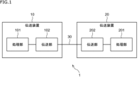
- FIG. 1 is a diagram illustrating a configuration example of an embodiment of a transmission system to which the present disclosure is applied.
- FIG. 11 is a diagram showing a first example of the configuration of an error notification packet to which the new method is applied.
- FIG. 13 is a diagram illustrating a second example of the configuration of an error notification packet to which the new method is applied.
- FIG. 1 is a diagram for explaining the IPG+Packet used in the current method.
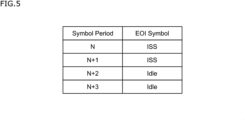
- FIG. 13 is a diagram showing the combination of ISS and Idle for EOI in the current method.
- FIG. 13 is a diagram for explaining PKTERR+MC to which the new method is applied.
- FIG. 13 is a diagram showing examples of combinations of ISS and Idle that are different from EOI when the new method is applied.
- FIG. 11 is a diagram showing a first example of the configuration of an error notification packet to which the new method is applied.
- FIG. 13 is a diagram illustrating a second example of the configuration of an error notification packet
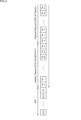
- FIG. 13 is a diagram showing the transmission of PKTERR+MC and additional information when the new method is applied. This figure shows an example of Control Nibbles applying the new method.
- FIG. 1 is a diagram for explaining CM+CN+MC to which the new method is applied.
- FIG. 13 is a diagram showing the transmission of CM+CN+MC and additional information to which the new method is applied.
- FIG. 13 is a diagram showing an example of a configuration of a source and a sink capable of handling the case where a downlink A-packet is corrupted or lost.
- 13 is a diagram showing a signal flow when an error notification packet is used to notify when a downlink A-packet is corrupted or missing.
- FIG. 1 is a diagram for explaining CM+CN+MC to which the new method is applied.
- FIG. 13 is a diagram showing the transmission of CM+CN+MC and additional information to which the new method is applied.
- FIG. 13 is a diagram showing an example of a configuration of
- FIG. 13 is a diagram showing the signal flow when notifying using CM+CN+MC when a downlink A-packet is corrupted or lost.
- FIG. FIG. 13 is a diagram showing an example of a configuration of a source and a sink that can handle the case where an uplink A-packet is corrupted or lost.
- 13 is a diagram showing the signal flow when an error notification packet is used to notify when an uplink A-packet is corrupted or lost.
- FIG. FIG. 13 is a diagram showing the signal flow when notifying using PKTERR+MC when an uplink A-packet is corrupted or lost.
- 11 is a flowchart illustrating a series of steps from when a source side detects corruption or loss of a received packet until notifying the sink side.
- FIG. 11 is a flowchart illustrating a flow of a reception failure notification and a notification analysis process performed between a source and a sink.
- a diagram showing an example of Adaptation Type. 11 is a flowchart illustrating a series of steps from when a damage or loss of a received packet is detected on the sink side until the source side is notified of the damage or loss.
- 11 is a flowchart illustrating a flow of a reception failure notification and a notification analysis process performed between a sink and a source.
- FIG. 11 is a sequence diagram showing signals exchanged between the source side and the sink side when the current method is used.
- FIG. 11 is a sequence diagram showing signals exchanged between the source side and the sink side when the new method is used.
- FIG. 1 is a diagram illustrating an example of the configuration of an embodiment of a transmission system to which the present disclosure is applied.
- the transmission system 1 is composed of a transmission device 10 and a transmission device 20.
- the transmission devices 10 and 20 exchange data via a transmission path 30 such as a cable.
- data transmission is performed between the transmission devices 10 and 20 via an A-PHY network.
- A-PHY is a standard defined by the MIPI Alliance as a physical layer for automotive SerDes. In this disclosure, the standard defined by the MIPI Alliance is referred to as the MIPI standard.
- the transmission device 10 comprises a processing unit 101 and a transmission unit 102.
- the processing unit 101 is composed of a chip that performs processing related to the Protocol Adaptation Layer (PAL), a CPU (Central Processing Unit) that controls the operation of each part of the transmission device 10, etc.
- the transmission unit 102 is composed of a chip that performs processing related to data transmission, etc.
- the transmission unit 102 performs processing related to A-PHY (processing of the PHY layer and Data Link layer).
- the processing unit 101 performs processing related to the upper layer, which is the layer above A-PHY.
- Transmission device 20 comprises a processing unit 201 and a transmission unit 202.
- Processing unit 201 is composed of a chip that performs PAL-related processing, a CPU that controls the operation of each part of transmission device 20, etc.
- Transmission unit 202 is composed of a chip that performs processing related to data transmission, etc. Transmission unit 202 performs processing related to A-PHY. Processing unit 201 performs processing related to the upper layer, which is the layer above A-PHY.
- one of the transmission devices 10 and 20 serves as a source and the other as a sink.
- the source and sink are defined in the MIPI standard, and the following explanation illustrates a case in which the transmission device 10 serves as a source and the transmission device 20 serves as a sink.
- transmission from the source to the sink is called a downlink
- transmission from the sink to the source is called an uplink.
- the transmission speed (communication speed) differs between the downlink and uplink, with the downlink being faster than the uplink.
- the processing unit 101 processes data in various formats such as GPIO (General Purpose Input/Output), I2C (Inter-Integrated Circuit), CSI2 (Camera Serial Interface 2), and SPI (Serial Peripheral Interface).
- GPIO General Purpose Input/Output
- I2C Inter-Integrated Circuit
- CSI2 Cara Serial Interface 2
- SPI Serial Peripheral Interface
- the sink transmission unit 202 detects the occurrence of the error and generates error notification data, which it transmits to the source transmission unit 102.
- the error notification data includes the MC number of the error packet, which is the A-packet in which the error was detected.
- the transmission unit 102 receives the error notification data transmitted from the transmission unit 202, it refers to the transmission table it holds and obtains the type of A-packet (protocol type) that corresponds to the MC number of the error packet contained in the error notification data. This enables the transmission unit 102 to restore the type of error packet and notify the processing unit 101.
- the transmission system 1 employs a method in which the transmission unit 102 or transmission unit 202 that processes A-PHY notifies the directly opposing transmission unit that an error has occurred in an A-packet transmitted between the source side transmission device 10 and the sink side transmission device 20.
- this new method any of the following three notification methods can be used.
- the first notification method is to define a new packet (Packet Error Notification Packet) for notifying of an A-packet error, and notify the occurrence of an error using that packet.
- the second notification method is to define a new PKTERR+MC format for the IPG+Packet used in the current method, and notify the occurrence of an A-packet error using PKTERR+MC. Details of IPG+Packet and PKTERR+MC will be given later.
- the third notification method is to define a new PER (Packet Error Indication) format for the CN (Control Nibbles) for the CM+CN used in the current method, and notify the occurrence of an A-packet error using CM+CN+MC. Details of CM+CN and CM+CN+MC will be given later. The three notification methods will be explained in detail below.
- a packet for notifying an error in an A-packet (Packet Error Notification Packet, hereinafter also referred to as an error notification packet) is newly defined, and the occurrence of an error is notified by this packet.
- Packet Error Notification Packet Packet Error Notification Packet
- Figure 2 shows a first example of the structure of an error notification packet to which the new method is applied.
- the error notification packet is structured as an A-Packet.
- the A-Packet is composed of an A-Packet Header, an A-Packet Payload, and an A-Packet Tail.
- the A-packet header contains the following fields: 8-bit Adaptation Descriptor, 8-bit Service Descriptor, 8-bit Placement Descriptor, 8-bit PHY2, 8-bit Target Address, 8-bit PHY3, 8-bit Payload Length, and 8-bit PHY Header CRC.
- the Adaptation Descriptor contains a 4-bit field for Adaptation Type, with the remaining bits being Reserved (Res).
- the Service Descriptor contains 2-bit fields for PHY1, 2-bit fields for Priority (Prio), 2-bit fields for Quality of Service (QoS), and 1-bit fields for Bad Indication (BAD), with the remaining bits being Reserved (Res).
- the Placement Descriptor contains 3-bit fields for Adaptation Layer specific information (ALEI), 1-bit fields for Odd-Bytes (OB), and 2-bit fields for Order, with the remaining bits being Reserved (Res).
- the Adaptation Type value of the Adaptation Descriptor is 4'h1.
- the Adaptation Type value is set to 1 (4'h1), it indicates that it is a Link service.
- the A-packet payload contains the fields BAD or DROP, MC number, and timestamp.
- BAD or DROP is a field in which a damaged/missing flag is placed, indicating that the error packet is a damaged (BAD) or missing (DROP) packet.
- MC number is a field in which the MC number of the error packet is placed.
- Timestamp is a field in which a timestamp is placed. Note that the error notification packet in Figure 2 is a packet defined by the Link service, and can be resent.
- Figure 3 is a diagram showing a second example of the configuration of an error notification packet to which the new method is applied.
- the error notification packet configured as an A-packet is configured in the same way as in Figure 2, but the Adaptation Type value is different. That is, in the A-packet header, the Adaptation Type value of the Adaptation Descriptor is 4'h0. When the Adaptation Type value is 0 (4'h0), it indicates a PHY service.
- the ALEI value is 3'b100.
- the A-packet payload includes fields that are BAD or DROP, MC number, and timestamp. Note that the error notification packet in Figure 3 is a packet defined by the PHY service, and cannot be resent.
- an error notification packet is defined as a packet for notifying an error in an A-packet in a packet defined in the Link service or PHY service specified in the MIPI standard, and the occurrence of an error can be notified by this packet.
- the first notification method can be used in both uplink and downlink.
- the source transmission unit 102 can send an error notification packet to the sink transmission unit 202 to notify the occurrence of an error in an A-packet.
- the sink transmission unit 202 can send an error notification packet to the source transmission unit 102 to notify the occurrence of an error in an A-packet.
- PKTERR+MC a new format of PKTERR+MC is defined for the IPG+Packet used in the current method, and the occurrence of a packet error is notified by PKTERR+MC.
- the second notification method can be used in the downlink.
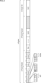
- FIG. 4 shows downlink transmission, with an IPG (interpacket gap) provided before the A-packet, which is represented by Header Tokens, Payload Data and CRC-32 Tokens.
- IPG interpacket gap
- Header Tokens Payload Data
- CRC-32 Tokens there is an IDLE state between A-packets.
- EOI End of Idle
- the EOI in the current method is defined by a combination of ISS and Idle, which are set for each Symbol Period.
- FIG. 6 is a diagram explaining PKTERR+MC when the new method is applied.
- Figure 6 shows downlink transmission, with PKTERR+MC being transmitted during IDLE in the IPG.
- PKTERR+MC consists of a code (PKTERR) indicating a packet error and an MC number (MC) added to that code.
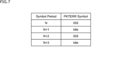
- PKTERR+MC can be notified by using a combination of ISS and Idle that differs from the EOI specified in the current method.
- Figure 7 is a diagram showing an example of a combination of ISS and Idle that differs from the EOI when the new method is applied. Compared to Figure 5, Figure 7 has a different combination of ISS and Idle set for each Symbol Period. This makes it possible to distinguish between EOI and PKTERR in the IPG.
- PKTERR code (a code other than 0) into the IDLE data sent between A-packets
- MC number added to PKTERR along with the PKTERR code indicating a packet error.
- additional information can be added to PKTERR+MC. For example, as shown in Figure 8, additional information such as BAD or DROP can be added, i.e., a damaged/missing flag indicating that the error packet is a damaged or missing packet.
- PKTERR+MC is defined and the occurrence of an A-packet error can be notified by this PKTERR+MC.
- the second notification method can be used in the downlink, for example, the source transmission unit 102 can send PKTERR+MC to the sink transmission unit 202 to notify the occurrence of an A-packet error. Since the second notification method uses a code, the data length can be shortened compared to when packets are used in the first notification method, and PKTERR+MC can be sent in a shorter time.
- CM+CN+MC ⁇ Third notification method>
- a new format of CM+CN is defined by newly defining PER (Packet Error Indication) in CN (Control Nibbles) for CM+CN used in the current system, and the occurrence of a packet error is notified by CM+CN+MC.
- the third notification method can be used in the uplink.
- Figure 9 shows an example of CNs (Control Nibbles) to which the new method is applied.
- Null, PS (Packet Start), PE (Packet End), RRS (Ret. Req. Start), RE (Req. End), GRS (Gap Req. Start), RTR (Re-Train Req.), CMR (sCMax Req.), INT (Interrupt)/PC (Packet Continue), and ACK (Ack Indication) are CNs defined in the current method.
- PER Packet Error Indication
- PER is a CN newly defined in the new method, and indicates a packet error.
- the PER code can use 0111, which is unused in the current method. This makes it possible to use the new CM+CN format.
- CNs include CN1 and CN2.
- each request or packet is sent by consecutively transmitting CM+CN, i.e., CM (Control Mark) and CN (Control Nibbles).
- CM+CN Control Mark
- CN Control Nibbles
- CM+CN+MC CM+CN+MC
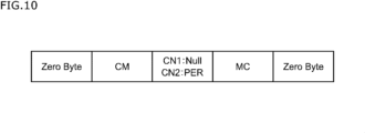
- Figure 10 is a diagram explaining CM+CN+MC to which the new method is applied.
- the MC following the CN notifies the MC number.
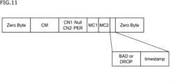
- the CM+CN+MC format is not limited to the format shown in FIG. 10, and other formats such as those shown in FIG. 11 may be adopted.
- multiple MC numbers can be specified using MC1 and MC2.
- multiple MC numbers can be specified in the range from MC1 to MC2, that is, in the range from the MC number specified in MC1 to the MC number specified in MC2. This makes it possible to notify multiple MC numbers when an error occurs in an A-packet.
- information such as BAD or DROP indicating a damaged/missing flag and a timestamp indicating a timestamp may be added.
- a CM+CN+MC is defined, and the occurrence of an error in an A-packet can be notified by the CM+CN+MC.
- the third notification method can be used in the uplink, and for example, the sink transmission unit 202 can send a CM+CN+MC to the source transmission unit 102 to notify the occurrence of an error in an A-packet. Since the third notification method uses a code, etc., the data length can be shortened compared to when packets are used in the first notification method, and the CM+CN+MC can be sent in a shorter time.
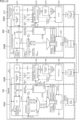
- Fig. 12 is a diagram showing an example of the configuration of a source and a sink that can handle a case where a downlink A-packet is damaged or lost.
- the transmission unit 102 of the transmission device 10 is shown as the configuration of the source
- the transmission unit 202 of the transmission device 20 is shown as the configuration of the sink.
- the source transmission section 102 is composed of a transmission system 102A and a reception system 102B.
- the transmission system 102A is composed of an RTS (Retransmission) 111 that performs processing related to retransmission, etc., a scrambler 112 that scrambles signals, etc.
- the reception system 102B is composed of a decoder 113 that decodes signals, a descrambler 114 that descrambles signals, a stream controller 115 that controls the stream, an RTS 116 that performs processing related to retransmission, etc.
- the sink transmission unit 202 is composed of a transmission system 202A and a reception system 202B.
- the transmission system 202A is composed of an RTS 211 that performs processing related to retransmission, etc., a stream controller 212 that controls the stream, a scrambler 213 that scrambles the signal, an encoder 214 that encodes the signal, a packet generation unit 217 that generates an error notification packet, etc.
- the reception system 202B is composed of a descrambler 215 that descrambles the signal, an RTS 216 that performs processing related to retransmission, etc.
- transmission system and reception system in transmission unit 102 and transmission unit 202 are separated for the sake of convenience of explanation, and part of the reception system may operate as necessary during transmission, or part of the transmission system may operate as necessary during reception.
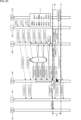
- Fig. 13 is a diagram showing the signal flow when an error occurrence is notified using an error notification packet when a downlink A-packet is corrupted or lost in the source and sink configuration of Fig. 12.
- the signal flow is represented by arrows with patterns.
- each unit of the transmission system 102A performs processing to transmit A-packets in the order of MC numbers in the transmission table T1 (S11).
- each unit of the reception system 202B performs processing to receive the A-packets transmitted from the transmission unit 102 (S12).
- the reception system 202B detects damage or loss of the received A-packet, and transfers the damaged packet to the processing unit 201, which performs processing related to the upper layer.
- the reception system 202B also notifies the packet generation unit 217 of the transmission system 202A of the MC number of the damaged A-packet (S13).
- the packet generation unit 217 generates an error notification packet with the notified MC number added (S13).
- each unit performs processing to transmit the error notification packet generated by the packet generation unit 217 (S14).
- each unit of the reception system 102B performs processing to receive the error notification packet transmitted from the transmission unit 202 (S15).
- the reception system 102B obtains the MC number of the corrupted A-packet from the received error notification packet and notifies the transmission system 102A (S16).
- the transmission system 102A obtains the protocol type of the notified target MC number from the transmission table T1 that is held even after the overall delay, and notifies the processing unit 101 that performs processing related to the upper layer (S17).
- it is defined that the packet is held for a certain period of time until a packet is not sent (or there is no possibility of it being sent) from the opposite side due to the overall delay, and is not held any longer.
- Fig. 14 is a diagram showing the signal flow when notifying the occurrence of an error using CM+CN+MC when a downlink A-packet is corrupted or lost in the source and sink configuration of Fig. 12.
- the signal flow is also represented by arrows with patterns.
- each unit of the transmission system 102A performs processing to transmit A-packets in the order of MC numbers in the transmission table T1 (S21).
- each unit of the reception system 202B performs processing to receive the A-packets transmitted from the transmission unit 102 (S22). At this time, it is assumed that the received A-packet is corrupted.
- the reception system 202B detects corruption or loss of the received A-packet, and transfers the corrupted packet to the processing unit 201, which performs processing related to the upper layer. The reception system 202B also notifies the transmission system 202A of the MC number of the corrupted A-packet (S23).
- the transmitting system 202A transmits the generated CM+CN+MC (S24).
- the transmitting unit 102 receives the CM+CN+MC transmitted from the transmitting unit 202 by each component of the receiving system 102B performing processing (S25).
- the third notification method available in the uplink is adopted, and the sink transmitting unit 202 transmits a CM+CN+MC to the source transmitting unit 102 to notify that an error has occurred in the A-packet.
- the receiving system 102B obtains the MC number of the corrupted A-packet from the received CM+CN+MC, and notifies the transmitting system 102A (S26).
- the transmission system 102A obtains the protocol type of the notified target MC number from the transmission table T1 that is still held after the overall delay, and notifies the processing unit 101, which performs processing related to the upper layer (S27).
- Fig. 15 is a diagram showing an example of the configuration of a source and a sink that can handle a case where an uplink A-packet is damaged or lost.
- the transmission unit 102 of the transmission device 10 is shown as the configuration of the source
- the transmission unit 202 of the transmission device 20 is shown as the configuration of the sink.
- the transmission unit 102 is configured in such a way that a packet generation unit 117 that generates an error notification packet is added to the transmission system 102A, as compared to the configuration shown in FIG. 12.
- the transmission unit 202 is configured in such a way that the packet generation unit 217 provided in the transmission system 202A is removed, as compared to the configuration shown in FIG. 12.
- the other configurations are the same as those shown in FIG. 12, and therefore their explanations are omitted.
- Fig. 16 is a diagram showing the signal flow when an error occurrence is notified using an error notification packet when an uplink A-packet is corrupted or lost in the source and sink configuration of Fig. 15.
- the signal flow is represented by arrows with patterns.
- each unit of the transmission system 202A performs processing to transmit A-packets in the order of MC numbers in the transmission table T2 (S31).
- each unit of the reception system 102B performs processing to receive A-packets transmitted from the transmission unit 202 (S32). At this time, it is assumed that the received A-packet is corrupted.
- the reception system 102B detects corruption or loss of the received A-packet, and transfers the corrupted packet to the processing unit 101, which performs processing related to the upper layer.
- the reception system 102B also notifies the packet generation unit 117 of the transmission system 102A of the MC number of the corrupted A-packet (S33).
- the packet generation unit 117 generates an error notification packet with the notified MC number added (S33).
- each unit performs processing to transmit the error notification packet generated by the packet generation unit 117 (S34).
- each unit of the reception system 202B performs processing to receive the error notification packet transmitted from the transmission unit 102 (S35).
- the reception system 202B obtains the MC number of the corrupted A-packet from the received error notification packet and notifies the transmission system 202A (S36).
- the transmission system 202A obtains the protocol type of the notified target MC number from the transmission table T2 that is still held after the overall delay, and notifies the processing unit 201 that performs processing related to the upper layer (S37).
- Fig. 17 is a diagram showing the signal flow when an error occurrence is notified using PKTERR+MC when an uplink A-packet is corrupted or lost in the source and sink configuration of Fig. 15. In Fig. 17, the signal flow is also represented by arrows with patterns.
- each unit of the transmission system 202A performs processing to transmit A-packets in the order of MC numbers in the transmission table T2 (S41).
- each unit of the reception system 102B performs processing to receive A-packets transmitted from the transmission unit 202 (S42). At this time, it is assumed that the received A-packet is damaged.
- the reception system 102B detects damage or loss of the received A-packet, and transfers the damaged packet to the processing unit 101, which performs processing related to the upper layer.
- the reception system 102B also notifies the transmission system 102A of the MC number of the damaged A-packet (S43).
- the transmission system 102A generates PKTERR+MC by adding the notified MC number to the code PKTERR (S43).
- the transmission system 102A transmits the generated PKTERR+MC (S44).
- the transmission unit 202 receives the PKTERR+MC transmitted from the transmission unit 102 by each unit of the reception system 202B performing processing (S45).
- the second notification method available in the downlink is adopted, and the source transmission unit 102 transmits PKTERR+MC to the sink transmission unit 202 to notify the occurrence of an error in the A-packet.
- the reception system 202B obtains the MC number of the corrupted A-packet from the received PKTERR+MC and notifies the transmission system 202A (S46).
- the transmission system 202A obtains the protocol type of the notified target MC number from the transmission table T2 that is held even after the overall delay, and notifies the processing unit 201 that performs processing related to the upper layer (S47).
- the processes of steps S111 to S123 are executed by the receiving system 102B of the source transmission unit 102. That is, the receiving system 102B receives an A-packet sent from the transmission unit 202 (S111), and judges whether the CRC8 of the header and the CRC32 of the data of the received A-packet are Good (no errors) (S112, S113). If it is judged that the CRC8 is not Good (No in S112), the corresponding packet is discarded (S114). Also, if it is judged that the CRC8 and CRC32 are Good (Yes in S112, Yes in S113), the MC number is Good.
- the MC number is BAD.
- the MC number information is written to the RTS buffer along with the received A-packet data (S115).
- the receiving system 102B reads the data written in the RTS buffer in the order of the MC numbers (S116) and judges whether the MC numbers are in order (S117). If it is judged that the MC numbers are in order (Yes in S117), it judges whether the data contains a BAD flag (S118). If it is judged that the data does not contain a BAD flag (No in S118), the normally received A-packet is forwarded to the upper layer (S123). On the other hand, if it is judged that the data contains a BAD flag (Yes in S118), it judges whether the overall delay has been exceeded (S120).
- step S116 If it is determined that the overall delay has not been exceeded (No in S119, No in S120), the process returns to step S116, the data written to the RTS buffer is read again in MC number order, and the above-mentioned process is repeated.
- the transmission system 102A uses the MC number of the damaged or lost A-packet to generate error notification data for notifying of failure to receive the A-packet (S141). Since this is a downlink, the first notification method can be used to generate an error notification packet, or the second notification method can be used to generate PKTERR+MC.
- the transmission system 102A scrambles the generated error notification data (S142), converts the scrambled signal from a parallel signal to a serial signal (S143), and transmits the converted signal (S144).
- the reception system 202B receives the signal transmitted from the transmission unit 102 by serial communication (S151), and converts the received signal from a serial signal to a parallel signal (S152). The reception system 202B also descrambles the converted signal (S153), and analyzes the resulting received signal (S154).
- the MC number of the damaged or missing A-packet is obtained from the error notification packet.
- the MC number of the damaged or missing A-packet is obtained from PKTERR+MC.
- the transmission system 202A then refers to the transmission table T2 to confirm that the MC number of the error packet obtained from the error notification data matches the MC number in the transmission packet buffer, obtains the packet type (protocol type) of the target MC number (S155), and notifies the upper layer (S156).
- the sink transmission unit 202 can restore the Adaptation Type contained in the Adaptation Descriptor in the header of the error packet from the MC number of the error packet obtained from the error notification data sent from the source transmission unit 102. This allows the sink transmission unit 202 to notify the upper layer for each adaptation type.
- Figures 20 and 21 show examples of adaptation types defined in the MIPI standard.
- steps S211 to S223 are the same as the processes of steps S111 to S123 (except for S122) in FIG. 18, except that the subject of the process is the receiving system 202B of the sink transmission unit 202, rather than the receiving system 102B of the source transmission unit 102.
- the process of step S222 in FIG. 22 is a process that applies the new method, and the details of this process will be described with reference to the flowchart of FIG. 23. In the flowchart of FIG.
- steps S241 to S244 are executed by the transmitting system 202A of the sink transmission unit 202, and the processes of steps S251 to S256 are executed by the receiving system 102B and part of the transmitting system 102A of the source transmission unit 102.
- the transmission system 202A uses the MC number of the damaged or lost A-packet to generate error notification data for notifying the failure to receive the A-packet (S241). Since this is an uplink, the first notification method can be used to generate an error notification packet, or the third notification method can be used to generate CM+CN+MC.
- the transmission system 202A scrambles the generated error notification data (S242), converts the scrambled signal from a parallel signal to a serial signal (S243), and transmits the converted signal (S244).
- the reception system 102B receives the signal transmitted from the transmission unit 202 by serial communication (S251), and converts the received signal from a serial signal to a parallel signal (S252).
- the reception system 102B also descrambles the converted signal (S253), and analyzes the resulting received signal (S254).
- the MC number of the damaged or missing A-packet is obtained from the error notification packet.
- the MC number of the damaged or missing A-packet is obtained from CM+CN+MC.
- the transmission system 102A refers to the transmission table T1 to confirm that the MC number of the error packet obtained from the error notification data matches the MC number in the transmission packet buffer, obtains the packet type (protocol type) of the target MC number (S255), and notifies the upper layer (S256).
- Fig. 24 is a sequence diagram showing signals exchanged between the source side and the sink side when the current method is used.
- the left side of the figure is the source side
- the right side of the figure is the sink side
- the direction of time is from the top to the bottom of the figure.
- the source side corresponds to the transmission device 10
- the System (CPU) and PAL correspond to the processing unit 101
- the Source Link corresponds to the transmission unit 102.
- the sink side corresponds to the transmission device 20
- the System (CPU) and PAL correspond to the processing unit 201
- the Sink Link corresponds to the transmission unit 202.
- the System supplies PAL with data in various formats, such as GPIO, I2C, and SPI.
- PAL generates A-packets from the data in the various formats (protocol types).
- Sink Link sequentially transmits the A-packets from PAL.
- an MC number is added to the A-packet.
- Table T can be used to associate and manage MC numbers and protocol types.
- the source side receives the A-packets sent from the sink side in order, and sends them from the Source Link to the PAL.
- the System In response to the interrupt request, the System notifies PAL of an error flag, which causes the Source Link to notify the sink side of an interrupt (GPIO Packet) from PAL. Then, on the sink side, the interrupt (GPIO Packet) notified from the source side is transferred from the Sink Link to PAL, and the System recognizes the error in the A-packet.
- Fig. 25 is a sequence diagram showing signals exchanged between the source side and the sink side when the new method is used.
- the left side of the figure is the source side and the right side of the figure is the sink side.
- the Source Link on the source side notifies the sink side of an A-packet error using error notification data with an MC number added, and the sink side can detect that an error has occurred in the A-packet it sent.
- the Sink Link on the sink side can refer to Table T to recover the type of damaged or missing A-packet from the MC number and notify the upper layer. This allows the sink side System to, for example, check the importance of the error packet and implement appropriate measures.
- the source transmission unit 102 can notify the directly opposing sink transmission unit 202 that an error has occurred in an A-packet, thereby shortening the processing time from the source side to the sink side. Also, by the source transmission unit 102 notifying the MC number of the A-packet in which the error has occurred, the opposing sink transmission unit 202 can recognize the packet type (protocol type) from the table T it holds. As a result, the system (CPU) can recognize the occurrence of an error at an early stage.
- the packet type program type
- the Source Link can directly notify the opposing Sink Link that an error has occurred in the packet, using a notification method such as the first notification method described above. Therefore, the time from time t1 after the maximum delay time has elapsed on the source side to time t3 when the System on the sink side recognizes the packet error is time T2. Therefore, comparing time T1 when the current method is used with time T2 when the new method is used, it is clear that the System can recognize the occurrence of an error more quickly by using the new method.
- a transmission system 1 composed of a transmission device 10 and a transmission device 20 connected via an A-PHY I/F defined in the MIPI standard has the following configuration. That is, the transmission device 10 includes a transmission unit 102, and when the transmission unit 102 detects an error in an A-packet transmitted from the transmission device 20, it generates error notification data to which the MC number of the error packet, which is the A-packet in which the error was detected, is added, and transmits the generated error notification data to the transmission device 20.
- the transmission device 20 also includes a transmission unit 202, which holds correspondence information that associates the type of the transmitted A-packet with the MC number of the A-packet, and when it receives error notification data transmitted from the transmission device 10, it obtains the type of A-packet corresponding to the MC number of the error packet added to the received error notification data from the held correspondence information, and restores the type of the error packet.
- a transmission unit 202 which holds correspondence information that associates the type of the transmitted A-packet with the MC number of the A-packet, and when it receives error notification data transmitted from the transmission device 10, it obtains the type of A-packet corresponding to the MC number of the error packet added to the received error notification data from the held correspondence information, and restores the type of the error packet.
- the transmission unit 102 is the source and the transmission unit 202 is the sink
- the error notification data is sent via a downlink, so the first or second notification method can be used, and an error notification packet or PKTERR+MC is generated as the error notification data.
- the corresponding information is, for example, the transmission table T2.
- the transmission unit 102 is the sink and the transmission unit 202 is the source
- the error notification data is sent via an uplink, so the first or third notification method can be used, and an error notification packet or CM+CN+MC is generated as the error notification data.
- the corresponding information is, for example, the transmission table T1.
- the transmission system 1 to which the present disclosure is applied has the above-described configuration and an error occurs in an A-packet being transmitted
- the error notification data with the MC number of the error packet added is exchanged between the transmission unit 102 and transmission unit 202, which perform processing related to the A-PHY, and the MC number of the error packet can be obtained and the error packet can be identified.
- the processing unit 101 or processing unit 201 which performs processing related to the upper layer, the occurrence of an error can be recognized early and processing can be performed. In this way, the transmission system 1 to which the present disclosure is applied can more appropriately notify a packet error when an error occurs in a packet.
- the first notification method, the second notification method, and the third notification method may be implemented individually, or may be implemented simultaneously in combination with a plurality of notification methods.
- the first notification method and the second notification method may be combined to generate and transmit both an error notification packet and PKTERR+MC.
- the first notification method and the third notification method may be combined to generate and transmit both an error notification packet and CM+CN+MC.
- the transmission table T1 and the transmission table T2 may be recorded and held in a storage device such as a RAM (Random Access Memory) of the transmission unit 102 and the transmission unit 202.
- the damaged/missing flag may indicate at least one of a damaged packet and a missing packet.
- the first transmission device When an error is detected in the A-packet transmitted from the second transmission device, generating error notification data to which is added an MC number of the error packet, which is the A-packet in which the error was detected; a first transmission unit that transmits the generated error notification data to the second transmission device; The second transmission device Hold correspondence information that associates the type of the transmitted A-packet with the MC number of the A-packet; a second transmission unit that, when receiving the error notification data transmitted from the first transmission device, obtains, from the stored correspondence information, a type of the A-packet corresponding to an MC number of the error packet added to the received error notification data, and restores the type of the error packet; A transmission system in which the first transmission unit and the second transmission unit perform processing related to A-PHY.
- the error notification data is an error notification packet composed of an A-packet, The transmission system according to (1), wherein the error notification packet includes the MC number in a payload. (3) The transmission system described in (2), wherein the payload further includes a flag indicating corruption or loss of the error packet. (4) The transmission system according to (2) or (3), wherein the error notification packet is a packet defined in a Link service or a PHY service defined in the MIPI standard. (5) The error notification data is a code indicating a packet error and the MC number added to the code, The transmission system described in (1) above, wherein the code includes a combination of Idle and ISS that is different from EOI.
- the error notification data is a CM and a CN transmitted successively, and the MC number added to the successive CM and the CN, The transmission system described in (1), wherein the CN includes a code indicating an error in the A-packet.
- the correspondence information is a table that is retained until a certain period of time has elapsed since the transmission of the A-packet.
- (10) Receives A-packets sent from other transmission devices connected via the A-PHY I/F defined in the MIPI standard, When an error in the A-packet is detected, error notification data is generated to which is added an MC number of the error packet, which is the A-packet in which the error was detected; a transmission unit that transmits the generated error notification data to the other transmission device; The transmission unit is a transmission device that performs processing related to A-PHY. (11) the error notification data is an error notification packet composed of an A-packet, The transmission device according to (10), wherein the error notification packet includes the MC number in a payload.
- the error notification data is a code indicating a packet error and the MC number added to the code,
- the error notification data is a CM and a CN transmitted successively, and the MC number added to the successive CM and the CN,
- a transmission method for a transmission device having a transmission unit that performs processing related to A-PHY defined in the MIPI standard The transmission unit is Receives A-packets sent from other transmission devices connected via the A-PHY I/F, When an error in the A-packet is detected, error notification data is generated to which is added an MC number of the error packet, which is the A-packet in which the error was detected; and transmitting the generated error notification data to the other transmission device.
- the error notification data is an error notification packet composed of an A-packet, The transmission device according to (15), wherein the error notification packet includes the MC number in a payload.
- the error notification data is a code indicating a packet error and the MC number added to the code, The transmission device described in (15) above, wherein the code includes a combination of Idle and ISS that is different from EOI.
- the error notification data is a CM and a CN transmitted successively, and the MC number added to the successive CM and the CN, The transmission device described in (15), wherein the CN includes a code indicating an error in the A-packet.
- a transmission method for a transmission device having a transmission unit that performs processing related to A-PHY defined in the MIPI standard The transmission unit is Transmitting an A-packet to another transmission device connected via the A-PHY I/F, Hold correspondence information that associates the type of the transmitted A-packet with the MC number of the A-packet;
- the type of the A-packet corresponding to the MC number of the error packet attached to the received error notification data is obtained from the stored correspondence information, and the type of the A-packet in which the error was detected and became the error packet is restored.
- 1 Transmission system 10 Transmission device, 20 Transmission device, 30 Transmission path, 101 Processing unit, 102 Transmission unit, 102A Transmission system, 102B Reception system, 111 RTS, 112 Scrambler, 113 Decoder, 114 Descrambler, 115 Stream controller, 116 RTS, 117 Packet generation unit, 201 Processing unit, 202 Transmission unit, 202A Transmission system, 202B Reception system, 211 RTS, 212 Stream controller, 213 Scrambler, 214 Encoder, 215 Descrambler, 216 RTS, 217 Packet generation unit
Landscapes
- Engineering & Computer Science (AREA)
- Computer Networks & Wireless Communication (AREA)
- Signal Processing (AREA)
- Theoretical Computer Science (AREA)
- Quality & Reliability (AREA)
- Physics & Mathematics (AREA)
- General Engineering & Computer Science (AREA)
- General Physics & Mathematics (AREA)
- Data Exchanges In Wide-Area Networks (AREA)
Abstract
Description
図1は、本開示を適用した伝送システムの一実施の形態の構成例を示す図である。
第1の通知方法では、A-パケットのエラーを通知するためのパケット(Packet Error Notification Packet,以下、エラー通知パケットともいう)を新たに定義して、当該パケットにより、エラーの発生を通知する。
第2の通知方法では、現行方式で用いられているIPG+Packetに対し、PKTERR+MCのフォーマットを新規に定義して、PKTERR+MCにより、パケットエラーの発生を通知する。第2の通知方法は、ダウンリンクで利用が可能となる。
第3の通知方法では、現行方式で用いられているCM+CNについて、CN(Control Nibbles)にPER(Packet Error Indication)を新たに定義することで、CM+CNの新規のフォーマットを定義して、CM+CN+MCにより、パケットエラーの発生を通知する。第3の通知方法は、アップリンクで利用が可能となる。
図12乃至図14を参照して、ダウンリンクのA-パケットが破損又は欠損した場合におけるソースとシンクの動作を説明する。図12は、ダウンリンクのA-パケットが破損又は欠損した場合に対応可能なソースとシンクの構成例を示す図である。図12においては、ソースの構成として、伝送装置10の伝送部102を示し、シンクの構成として、伝送装置20の伝送部202を示している。
図13は、図12のソースとシンクの構成で、ダウンリンクのA-パケットが破損又は欠損した場合に、エラー通知パケットを利用してエラーの発生を通知するときの信号の流れを示す図である。図13では、信号の流れを、模様を付した矢印で表している。
図14は、図12のソースとシンクの構成で、ダウンリンクのA-パケットが破損又は欠損した場合に、CM+CN+MCを利用してエラーの発生を通知するときの信号の流れを示す図である。図14でも、信号の流れを、模様を付した矢印で表している。
図15乃至図17を参照して、アップリンクのA-パケットが破損又は欠損した場合におけるソースとシンクの動作を説明する。図15は、アップリンクのA-パケットが破損又は欠損した場合に対応可能なソースとシンクの構成例を示す図である。図15においては、図12と同様に、ソースの構成として、伝送装置10の伝送部102を示し、シンクの構成として、伝送装置20の伝送部202を示している。
図16は、図15のソースとシンクの構成で、アップリンクのA-パケットが破損又は欠損した場合に、エラー通知パケットを利用してエラーの発生を通知するときの信号の流れを示す図である。図16では、信号の流れを、模様を付した矢印で表している。
図17は、図15のソースとシンクの構成で、アップリンクのA-パケットが破損又は欠損した場合に、PKTERR+MCを利用してエラーの発生を通知するときの信号の流れを示す図である。図17でも、信号の流れを、模様を付した矢印で表している。
<<a.ソース側で破損/欠損を検出>>
図18,図19のフローチャートを参照して、ソース側で受信パケットの破損又は欠損を検出した場合にシンク側に通知するまでの一連の流れを説明する。図18,図19の説明では、伝送装置10(の伝送部102)がソースとなり、伝送装置20(の伝送部202)がシンクとなる場合を例示する。
次に、図22,図23のフローチャートを参照して、シンク側で受信パケットの破損又は欠損を検出した場合にソース側に通知するまでの一連の流れを説明する。図22,図23の説明では、図18,図19と同様に、伝送装置10(の伝送部102)がソースとなり、伝送装置20(の伝送部202)がシンクとなる場合を例示する。
新方式を採用することで得られる効果について説明する。ここでは、図24,図25を参照して、新方式を採用した場合、A-パケットが破損又は欠損したときに上位層に通知するまでの時間を短縮できることを、現行方式を採用した場合と比較しながら説明する。
図24は、現行方式を用いた場合におけるソース側とシンク側でやり取りされる信号を示したシーケンス図である。図24においては、図中の左側がソース側で、図中の右側がシンク側となり、時間の方向は、図中の上側から下側に向かう方向となる。ソース側が伝送装置10に対応する場合、System(CPU)とPALが処理部101に対応し、Source Linkが伝送部102に対応する。シンク側が伝送装置20に対応する場合、System(CPU)とPALが処理部201に対応し、Sink Linkが伝送部202に対応する。
図25は、新方式を用いた場合におけるソース側とシンク側でやり取りされる信号を示したシーケンス図である。図25においては、図24と同様に、図中の左側がソース側で、図中の右側がシンク側となる場合に、ソース側では、シンク側から送信されるA-パケットを順に受信しているが、伝送路にノイズ(Noise)が発生して、MC=2, 3のA-パケットからCRC32エラーが検出され、再送信の要求が行われる。シンク側では、ソース側からの再送信の要求に応じて、A-パケット(MC=3),A-パケット(MC=2)を再送するが、ソース側では、再送されたA-パケット(MC=2)を受信する前に、最大遅延時間(MC=2 Max RTS Delay)を超えているため、A-パケット(MC=2)が破損(BAD)していることをPALに通知し、Systemの処理中に割り込み(interrupt)を要求する。
上述した説明では、新方式として3つの通知方法を説明したが、第1の通知方法、第2の通知方法、及び第3の通知方法は、それぞれの通知方法を単独で実施することは勿論、複数の通知方法を組み合わせて同時に実施しても構わない。例えば、ダウンリンクにおいて、第1の通知方法と第2の通知方法を組み合わせて、エラー通知パケットとPKTERR+MCの両方を生成して送信することができる。また、アップリンクにおいて、第1の通知方法と第3の通知方法を組み合わせて、エラー通知パケットとCM+CN+MCの両方を生成して送信することができる。なお、送信テーブルT1、送信テーブルT2は、伝送部102、伝送部202が有するRAM(Random Access Memory)等の記憶装置に記録して保持することができる。なお、破損/欠損フラグは、破損パケットと欠損パケットの少なくとも一方を示すようにしてもよい。
MIPI規格で規定されたA-PHY I/Fを介して接続された第1の伝送装置と第2の伝送装置から構成される伝送システムにおいて、
前記第1の伝送装置は、
前記第2の伝送装置から送信されるA-パケットのエラーを検出した場合、エラーを検出した前記A-パケットであるエラーパケットのMC番号を付加したエラー通知データを生成し、
生成した前記エラー通知データを前記第2の伝送装置に送信する
第1の伝送部を備え、
前記第2の伝送装置は、
送信した前記A-パケットの種類と前記A-パケットのMC番号とを対応付けた対応情報を保持し、
前記第1の伝送装置から送信される前記エラー通知データを受信した場合、保持した前記対応情報から、受信した前記エラー通知データに付加された前記エラーパケットのMC番号に対応した前記A-パケットの種類を取得し、前記エラーパケットの種類を復元する
第2の伝送部を備え、
前記第1の伝送部と前記第2の伝送部は、A-PHYに関する処理を行う
伝送システム。
(2)
前記エラー通知データは、A-パケットで構成されるエラー通知パケットであり、
前記エラー通知パケットは、前記MC番号をペイロードに含む
前記(1)に記載の伝送システム。
(3)
前記ペイロードは、前記エラーパケットの破損又は欠損を示すフラグをさらに含む
前記(2)に記載の伝送システム。
(4)
前記エラー通知パケットは、前記MIPI規格で規定されたLinkサービス又はPHYサービスで定義されるパケットである
前記(2)又は(3)に記載の伝送システム。
(5)
前記エラー通知データは、パケットエラーを示すコードと前記コードに付加した前記MC番号であり、
前記コードは、EOIと異なるIdleとISSの組み合わせを含む
前記(1)に記載の伝送システム。
(6)
前記コードには、前記エラーパケットの破損又は欠損を示すフラグがさらに付加される
前記(5)に記載の伝送システム。
(7)
前記エラー通知データは、連続して伝送されるCMとCNと、連続した前記CMと前記CNに付加した前記MC番号であり、
前記CNは、前記A-パケットのエラーを示すコードを含む
前記(1)に記載の伝送システム。
(8)
連続した前記CMと前記CNには、前記エラーパケットの破損又は欠損を示すフラグがさらに付加される
前記(7)に記載の伝送システム。
(9)
前記対応情報は、前記A-パケットの送信時から一定期間を経過するまで保持するテーブルである
前記(1)乃至(8)のいずれかに記載の伝送システム。
(10)
MIPI規格で規定されたA-PHY I/Fを介して接続された他の伝送装置から送信されるA-パケットを受信し、
前記A-パケットのエラーを検出した場合、エラーを検出した前記A-パケットであるエラーパケットのMC番号を付加したエラー通知データを生成し、
生成した前記エラー通知データを前記他の伝送装置に送信する
伝送部を備え、
前記伝送部は、A-PHYに関する処理を行う
伝送装置。
(11)
前記エラー通知データは、A-パケットで構成されるエラー通知パケットであり、
前記エラー通知パケットは、前記MC番号をペイロードに含む
前記(10)に記載の伝送装置。
(12)
前記エラー通知データは、パケットエラーを示すコードと前記コードに付加した前記MC番号であり、
前記コードは、EOIと異なるIdleとISSの組み合わせを含む
前記(10)に記載の伝送装置。
(13)
前記エラー通知データは、連続して伝送されるCMとCNと、連続した前記CMと前記CNに付加した前記MC番号であり、
前記CNは、前記A-パケットのエラーを示すコードを含む
前記(10)に記載の伝送装置。
(14)
MIPI規格で規定されたA-PHYに関する処理を行う伝送部を備える伝送装置の伝送方法であって、
前記伝送部が、
A-PHY I/Fを介して接続された他の伝送装置から送信されるA-パケットを受信し、
前記A-パケットのエラーを検出した場合、エラーを検出した前記A-パケットであるエラーパケットのMC番号を付加したエラー通知データを生成し、
生成した前記エラー通知データを前記他の伝送装置に送信する
伝送方法。
(15)
MIPI規格で規定されたA-PHY I/Fを介して接続された他の伝送装置に、A-パケットを送信し、
送信した前記A-パケットの種類と前記A-パケットのMC番号とを対応付けた対応情報を保持し、
前記他の伝送装置から送信されるエラー通知データを受信した場合、保持した前記対応情報から、受信した前記エラー通知データに付加されたエラーパケットのMC番号に対応した前記A-パケットの種類を取得し、前記エラーパケットとなってエラーが検出された前記A-パケットの種類を復元する
伝送部を備え、
前記伝送部は、A-PHYに関する処理を行う
伝送装置。
(16)
前記エラー通知データは、A-パケットで構成されるエラー通知パケットであり、
前記エラー通知パケットは、前記MC番号をペイロードに含む
前記(15)に記載の伝送装置。
(17)
前記エラー通知データは、パケットエラーを示すコードと前記コードに付加した前記MC番号であり、
前記コードは、EOIと異なるIdleとISSの組み合わせを含む
前記(15)に記載の伝送装置。
(18)
前記エラー通知データは、連続して伝送されるCMとCNと、連続した前記CMと前記CNに付加した前記MC番号であり、
前記CNは、前記A-パケットのエラーを示すコードを含む
前記(15)に記載の伝送装置。
(19)
MIPI規格で規定されたA-PHYに関する処理を行う伝送部を備える伝送装置の伝送方法であって、
前記伝送部が、
A-PHY I/Fを介して接続された他の伝送装置に、A-パケットを送信し、
送信した前記A-パケットの種類と前記A-パケットのMC番号とを対応付けた対応情報を保持し、
前記他の伝送装置から送信されるエラー通知データを受信した場合、保持した前記対応情報から、受信した前記エラー通知データに付加されたエラーパケットのMC番号に対応した前記A-パケットの種類を取得し、前記エラーパケットとなってエラーが検出された前記A-パケットの種類を復元する
伝送方法。
Claims (19)
- MIPI規格で規定されたA-PHY I/Fを介して接続された第1の伝送装置と第2の伝送装置から構成される伝送システムにおいて、
前記第1の伝送装置は、
前記第2の伝送装置から送信されるA-パケットのエラーを検出した場合、エラーを検出した前記A-パケットであるエラーパケットのMC番号を付加したエラー通知データを生成し、
生成した前記エラー通知データを前記第2の伝送装置に送信する
第1の伝送部を備え、
前記第2の伝送装置は、
送信した前記A-パケットの種類と前記A-パケットのMC番号とを対応付けた対応情報を保持し、
前記第1の伝送装置から送信される前記エラー通知データを受信した場合、保持した前記対応情報から、受信した前記エラー通知データに付加された前記エラーパケットのMC番号に対応した前記A-パケットの種類を取得し、前記エラーパケットの種類を復元する
第2の伝送部を備え、
前記第1の伝送部と前記第2の伝送部は、A-PHYに関する処理を行う
伝送システム。 - 前記エラー通知データは、A-パケットで構成されるエラー通知パケットであり、
前記エラー通知パケットは、前記MC番号をペイロードに含む
請求項1に記載の伝送システム。 - 前記ペイロードは、前記エラーパケットの破損又は欠損を示すフラグをさらに含む
請求項2に記載の伝送システム。 - 前記エラー通知パケットは、前記MIPI規格で規定されたLinkサービス又はPHYサービスで定義されるパケットである
請求項2に記載の伝送システム。 - 前記エラー通知データは、パケットエラーを示すコードと前記コードに付加した前記MC番号であり、
前記コードは、EOIと異なるIdleとISSの組み合わせを含む
請求項1に記載の伝送システム。 - 前記コードには、前記エラーパケットの破損又は欠損を示すフラグがさらに付加される
請求項5に記載の伝送システム。 - 前記エラー通知データは、連続して伝送されるCMとCNと、連続した前記CMと前記CNに付加した前記MC番号であり、
前記CNは、前記A-パケットのエラーを示すコードを含む
請求項1に記載の伝送システム。 - 連続した前記CMと前記CNには、前記エラーパケットの破損又は欠損を示すフラグがさらに付加される
請求項7に記載の伝送システム。 - 前記対応情報は、前記A-パケットの送信時から一定期間を経過するまで保持するテーブルである
請求項1に記載の伝送システム。 - MIPI規格で規定されたA-PHY I/Fを介して接続された他の伝送装置から送信されるA-パケットを受信し、
前記A-パケットのエラーを検出した場合、エラーを検出した前記A-パケットであるエラーパケットのMC番号を付加したエラー通知データを生成し、
生成した前記エラー通知データを前記他の伝送装置に送信する
伝送部を備え、
前記伝送部は、A-PHYに関する処理を行う
伝送装置。 - 前記エラー通知データは、A-パケットで構成されるエラー通知パケットであり、
前記エラー通知パケットは、前記MC番号をペイロードに含む
請求項10に記載の伝送装置。 - 前記エラー通知データは、パケットエラーを示すコードと前記コードに付加した前記MC番号であり、
前記コードは、EOIと異なるIdleとISSの組み合わせを含む
請求項10に記載の伝送装置。 - 前記エラー通知データは、連続して伝送されるCMとCNと、連続した前記CMと前記CNに付加した前記MC番号であり、
前記CNは、前記A-パケットのエラーを示すコードを含む
請求項10に記載の伝送装置。 - MIPI規格で規定されたA-PHYに関する処理を行う伝送部を備える伝送装置の伝送方法であって、
前記伝送部が、
A-PHY I/Fを介して接続された他の伝送装置から送信されるA-パケットを受信し、
前記A-パケットのエラーを検出した場合、エラーを検出した前記A-パケットであるエラーパケットのMC番号を付加したエラー通知データを生成し、
生成した前記エラー通知データを前記他の伝送装置に送信する
伝送方法。 - MIPI規格で規定されたA-PHY I/Fを介して接続された他の伝送装置に、A-パケットを送信し、
送信した前記A-パケットの種類と前記A-パケットのMC番号とを対応付けた対応情報を保持し、
前記他の伝送装置から送信されるエラー通知データを受信した場合、保持した前記対応情報から、受信した前記エラー通知データに付加されたエラーパケットのMC番号に対応した前記A-パケットの種類を取得し、前記エラーパケットとなってエラーが検出された前記A-パケットの種類を復元する
伝送部を備え、
前記伝送部は、A-PHYに関する処理を行う
伝送装置。 - 前記エラー通知データは、A-パケットで構成されるエラー通知パケットであり、
前記エラー通知パケットは、前記MC番号をペイロードに含む
請求項15に記載の伝送装置。 - 前記エラー通知データは、パケットエラーを示すコードと前記コードに付加した前記MC番号であり、
前記コードは、EOIと異なるIdleとISSの組み合わせを含む
請求項15に記載の伝送装置。 - 前記エラー通知データは、連続して伝送されるCMとCNと、連続した前記CMと前記CNに付加した前記MC番号であり、
前記CNは、前記A-パケットのエラーを示すコードを含む
請求項15に記載の伝送装置。 - MIPI規格で規定されたA-PHYに関する処理を行う伝送部を備える伝送装置の伝送方法であって、
前記伝送部が、
A-PHY I/Fを介して接続された他の伝送装置に、A-パケットを送信し、
送信した前記A-パケットの種類と前記A-パケットのMC番号とを対応付けた対応情報を保持し、
前記他の伝送装置から送信されるエラー通知データを受信した場合、保持した前記対応情報から、受信した前記エラー通知データに付加されたエラーパケットのMC番号に対応した前記A-パケットの種類を取得し、前記エラーパケットとなってエラーが検出された前記A-パケットの種類を復元する
伝送方法。
Priority Applications (4)
| Application Number | Priority Date | Filing Date | Title |
|---|---|---|---|
| CN202480015660.9A CN120814195A (zh) | 2023-03-06 | 2024-02-20 | 传输系统、传输装置和传输方法 |
| DE112024001114.4T DE112024001114T5 (de) | 2023-03-06 | 2024-02-20 | Übertragungssystem, Übertragungsvorrichtung und Übertragungsverfahren |
| KR1020257029661A KR20250158761A (ko) | 2023-03-06 | 2024-02-20 | 전송 시스템, 전송 장치 및 전송 방법 |
| JP2025505192A JPWO2024185482A1 (ja) | 2023-03-06 | 2024-02-20 |
Applications Claiming Priority (2)
| Application Number | Priority Date | Filing Date | Title |
|---|---|---|---|
| JP2023033701 | 2023-03-06 | ||
| JP2023-033701 | 2023-03-06 |
Publications (1)
| Publication Number | Publication Date |
|---|---|
| WO2024185482A1 true WO2024185482A1 (ja) | 2024-09-12 |
Family
ID=92674654
Family Applications (1)
| Application Number | Title | Priority Date | Filing Date |
|---|---|---|---|
| PCT/JP2024/005922 Ceased WO2024185482A1 (ja) | 2023-03-06 | 2024-02-20 | 伝送システム、伝送装置、及び伝送方法 |
Country Status (5)
| Country | Link |
|---|---|
| JP (1) | JPWO2024185482A1 (ja) |
| KR (1) | KR20250158761A (ja) |
| CN (1) | CN120814195A (ja) |
| DE (1) | DE112024001114T5 (ja) |
| WO (1) | WO2024185482A1 (ja) |
Citations (2)
| Publication number | Priority date | Publication date | Assignee | Title |
|---|---|---|---|---|
| WO2021215269A1 (ja) * | 2020-04-24 | 2021-10-28 | ソニーセミコンダクタソリューションズ株式会社 | 送信装置、受信装置、および通信システム |
| WO2022172698A1 (ja) * | 2021-02-09 | 2022-08-18 | ソニーセミコンダクタソリューションズ株式会社 | 情報処理装置、移動体装置、および通信システム |
-
2024
- 2024-02-20 WO PCT/JP2024/005922 patent/WO2024185482A1/ja not_active Ceased
- 2024-02-20 DE DE112024001114.4T patent/DE112024001114T5/de active Pending
- 2024-02-20 KR KR1020257029661A patent/KR20250158761A/ko active Pending
- 2024-02-20 JP JP2025505192A patent/JPWO2024185482A1/ja active Pending
- 2024-02-20 CN CN202480015660.9A patent/CN120814195A/zh active Pending
Patent Citations (2)
| Publication number | Priority date | Publication date | Assignee | Title |
|---|---|---|---|---|
| WO2021215269A1 (ja) * | 2020-04-24 | 2021-10-28 | ソニーセミコンダクタソリューションズ株式会社 | 送信装置、受信装置、および通信システム |
| WO2022172698A1 (ja) * | 2021-02-09 | 2022-08-18 | ソニーセミコンダクタソリューションズ株式会社 | 情報処理装置、移動体装置、および通信システム |
Non-Patent Citations (1)
| Title |
|---|
| SHIN SANG-UNG; KANG JIN-KU; KIM YONGWOO: "A Design and Implementation of MIPI A-PHY RTS Layer", 2022 19TH INTERNATIONAL SOC DESIGN CONFERENCE (ISOCC), IEEE, 19 October 2022 (2022-10-19), pages 326 - 327, XP034288579, DOI: 10.1109/ISOCC56007.2022.10031592 * |
Also Published As
| Publication number | Publication date |
|---|---|
| CN120814195A (zh) | 2025-10-17 |
| DE112024001114T5 (de) | 2025-12-24 |
| KR20250158761A (ko) | 2025-11-06 |
| JPWO2024185482A1 (ja) | 2024-09-12 |
Similar Documents
| Publication | Publication Date | Title |
|---|---|---|
| JP5408981B2 (ja) | 通信装置、及び通信方法、プログラム | |
| CN101636979A (zh) | 通过无线通信信道传输未压缩视频的方法和系统 | |
| CN106911426A (zh) | 一种灵活以太网中传输数据的方法及设备 | |
| CN107888345B (zh) | 一种信息传输的方法和设备 | |
| CN108156074A (zh) | 保护倒换方法、网络设备及系统 | |
| JP2004242294A (ja) | ステータス情報を伝達するcrc符号化方式 | |
| CN103297186A (zh) | 数据传送设备、数据传送系统和数据传送方法 | |
| US20090303871A1 (en) | Method and apparatus for packet aggregation according to traffic characteristics | |
| WO2018201960A1 (zh) | 一种进行反馈的方法和设备 | |
| CN116260553A (zh) | 数据重传的方法、装置及系统 | |
| TW201836328A (zh) | 一種協定資料單元傳輸資料的方法及裝置 | |
| CN100593305C (zh) | 接收装置和方法、以及程序 | |
| CN115086192A (zh) | 一种数据处理方法、装置、系统及监控卡 | |
| JP2007520148A (ja) | データフレームの再伝送方法および前記方法を用いるネットワーク装置 | |
| US7865549B2 (en) | Method and apparatus for transmitting data frame efficiently in communication network | |
| WO2024185482A1 (ja) | 伝送システム、伝送装置、及び伝送方法 | |
| CN110677871B (zh) | 数据发送方法及发送设备、数据接收方法及接收设备 | |
| TWI661730B (zh) | 無線通信方法及設備 | |
| JP7416207B2 (ja) | 送信局及び受信局 | |
| TWI748839B (zh) | 具有資料重用機制的資料傳輸方法及裝置 | |
| US20180248808A1 (en) | Communication method, communication apparatus, and program | |
| CN101427496A (zh) | 根据估计错误率设置传输的长度 | |
| CN119788247A (zh) | 基于ip层的数据传输的方法、计算机可读介质及电子设备 | |
| JPH0955718A (ja) | データ通信装置 | |
| US7389469B2 (en) | Bus systems, apparatuses, and methods of operating a bus |
Legal Events
| Date | Code | Title | Description |
|---|---|---|---|
| 121 | Ep: the epo has been informed by wipo that ep was designated in this application |
Ref document number: 24766853 Country of ref document: EP Kind code of ref document: A1 |
|
| ENP | Entry into the national phase |
Ref document number: 2025505192 Country of ref document: JP Kind code of ref document: A |
|
| WWE | Wipo information: entry into national phase |
Ref document number: 2025505192 Country of ref document: JP |
|
| WWE | Wipo information: entry into national phase |
Ref document number: 202480015660.9 Country of ref document: CN |
|
| ENP | Entry into the national phase |
Ref document number: 1020257029661 Country of ref document: KR Free format text: ST27 STATUS EVENT CODE: A-0-1-A10-A15-NAP-PA0105 (AS PROVIDED BY THE NATIONAL OFFICE) |
|
| WWE | Wipo information: entry into national phase |
Ref document number: 112024001114 Country of ref document: DE |
|
| WWP | Wipo information: published in national office |
Ref document number: 202480015660.9 Country of ref document: CN |
|
| WWP | Wipo information: published in national office |
Ref document number: 112024001114 Country of ref document: DE |
|
| 122 | Ep: pct application non-entry in european phase |
Ref document number: 24766853 Country of ref document: EP Kind code of ref document: A1 |