WO2024185463A1 - ガス圧縮機 - Google Patents
ガス圧縮機 Download PDFInfo
- Publication number
- WO2024185463A1 WO2024185463A1 PCT/JP2024/005494 JP2024005494W WO2024185463A1 WO 2024185463 A1 WO2024185463 A1 WO 2024185463A1 JP 2024005494 W JP2024005494 W JP 2024005494W WO 2024185463 A1 WO2024185463 A1 WO 2024185463A1
- Authority
- WO
- WIPO (PCT)
- Prior art keywords
- gas
- hydraulic
- booster
- gas booster
- valve
- Prior art date
- Legal status (The legal status is an assumption and is not a legal conclusion. Google has not performed a legal analysis and makes no representation as to the accuracy of the status listed.)
- Ceased
Links
Images

Classifications
-
- F—MECHANICAL ENGINEERING; LIGHTING; HEATING; WEAPONS; BLASTING
- F04—POSITIVE - DISPLACEMENT MACHINES FOR LIQUIDS; PUMPS FOR LIQUIDS OR ELASTIC FLUIDS
- F04B—POSITIVE-DISPLACEMENT MACHINES FOR LIQUIDS; PUMPS
- F04B31/00—Free-piston pumps specially adapted for elastic fluids; Systems incorporating such pumps
-
- F—MECHANICAL ENGINEERING; LIGHTING; HEATING; WEAPONS; BLASTING
- F04—POSITIVE - DISPLACEMENT MACHINES FOR LIQUIDS; PUMPS FOR LIQUIDS OR ELASTIC FLUIDS
- F04B—POSITIVE-DISPLACEMENT MACHINES FOR LIQUIDS; PUMPS
- F04B39/00—Component parts, details, or accessories, of pumps or pumping systems specially adapted for elastic fluids, not otherwise provided for in, or of interest apart from, groups F04B25/00 - F04B37/00
- F04B39/12—Casings; Cylinders; Cylinder heads; Fluid connections
-
- F—MECHANICAL ENGINEERING; LIGHTING; HEATING; WEAPONS; BLASTING
- F04—POSITIVE - DISPLACEMENT MACHINES FOR LIQUIDS; PUMPS FOR LIQUIDS OR ELASTIC FLUIDS
- F04B—POSITIVE-DISPLACEMENT MACHINES FOR LIQUIDS; PUMPS
- F04B9/00—Piston machines or pumps characterised by the driving or driven means to or from their working members
- F04B9/08—Piston machines or pumps characterised by the driving or driven means to or from their working members the means being fluid
- F04B9/12—Piston machines or pumps characterised by the driving or driven means to or from their working members the means being fluid the fluid being elastic, e.g. steam or air
- F04B9/129—Piston machines or pumps characterised by the driving or driven means to or from their working members the means being fluid the fluid being elastic, e.g. steam or air having plural pumping chambers
- F04B9/137—Piston machines or pumps characterised by the driving or driven means to or from their working members the means being fluid the fluid being elastic, e.g. steam or air having plural pumping chambers the pumping members not being mechanically connected to each other
Definitions
- This disclosure relates to a hydraulically driven gas compressor.
- Hydraulically driven gas compressors have been known for some time.
- gas compressors are used as large gas compressors.
- Patent Document 1 discloses a gas compressor including two gas boosters. Each gas booster includes a gas cylinder and a hydraulic cylinder that are coaxially aligned.
- each gas booster includes a gas cylinder tube, a gas cover and a gas piston
- the hydraulic cylinder includes a hydraulic cylinder tube, a pair of hydraulic covers and a hydraulic piston.
- the gas cover closes one opening of the gas cylinder tube on the side opposite the hydraulic cylinder, and the gas piston is disposed within the gas cylinder tube to form a compression chamber between the gas cover.
- a pair of hydraulic covers also closes both openings of the hydraulic cylinder tube, and the hydraulic piston is disposed within the hydraulic cylinder tube to form a pair of drive chambers between the pair of hydraulic covers.
- the gas piston and hydraulic piston are connected by a rod that passes through the hydraulic cover on the gas cylinder side.
- the axial direction of the gas cylinder and hydraulic cylinder is vertical. This allows the installation area of the gas compressor to be reduced.
- the hydraulic cylinder of the gas booster together with the hydraulic pump, constitutes a hydraulic circuit.
- the hydraulic pump may also constitute a pump unit together with an electric motor that drives the hydraulic pump. In such gas compressors, it is desirable to improve the maintainability of the components such as the gas booster and the pump unit.
- the present disclosure therefore aims to provide a gas compressor that can improve the maintainability of the component equipment while keeping the installation area small.
- the present disclosure provides a gas compressor comprising: a stand; at least one gas booster including a gas cylinder and a hydraulic cylinder arranged coaxially, the axial direction of the gas cylinder and the hydraulic cylinder being vertical, the pump unit being positioned at a position different from the gas booster in a plan view and including a hydraulic pump constituting a hydraulic circuit together with the hydraulic cylinder and an electric motor for driving the hydraulic pump; and a manifold being positioned at a position different from the gas booster and the hydraulic pump in a plan view, the manifold having a flow path formed therein and constituting a part of the hydraulic circuit.
- the present disclosure provides a gas compressor that can improve the maintainability of the component equipment while keeping the installation area small.
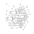
- FIG. 1 is a perspective view of a gas compressor according to one embodiment.
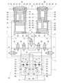
- FIG. 2 is a hydraulic circuit diagram of the gas compressor.
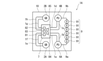
- FIG. 2 is a schematic plan view of the gas compressor.
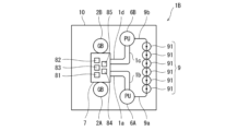
- FIG. 2 is a schematic plan view of a gas compressor according to a first modified example.
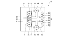
- FIG. 11 is a schematic plan view of a gas compressor according to a second modified example.
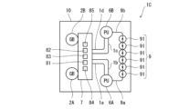
- FIG. 13 is a schematic plan view of a gas compressor according to a third modified example.
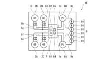
- FIG. 13 is a schematic plan view of a gas compressor according to a fourth modified example.
- FIG. 13 is a schematic plan view of a gas compressor according to a fifth modified example.
- FIG. 1 shows a gas compressor 1A according to one embodiment.
- the gas compressor 1A includes a first gas booster 2A and a second gas booster 2B as components, and compresses gas in two stages.
- the gas to be compressed is not particularly limited, but is, for example, hydrogen.
- the gas compressor 1A includes a stand 10, and also includes two pump units 6A and 6B, a manifold 7, and a tank 9 as components other than the first gas booster 2A and the second gas booster 2B.
- the gas compressor 1A may include only one of the pump units 6A and 6B.
- the pump units 6A and 6B are located at a different position from the first gas booster 2A and the second gas booster 2B in a plan view, and the manifold 7 is located at a different position from the first gas booster 2A and the second gas booster 2B and the pump units 6A and 6B in a plan view.
- the first gas booster 2A and the second gas booster 2B are spaced apart from each other laterally.
- the base 10 is a rectangular plate, and the first gas booster 2A and the second gas booster 2B are arranged at both corners of one side of the base 10.
- the manifold 7 is arranged between the first gas booster 2A and the second gas booster 2B in the direction in which the first gas booster 2A and the second gas booster 2B are spaced apart. This allows the gas compressor 1A to be made compact in the direction perpendicular to the direction in which the first gas booster 2A and the second gas booster 2B are spaced apart.
- the manifold 7 is spaced upward from the stand 10 and positioned below the upper ends of the first gas booster 2A and the second gas booster 2B.
- the manifold 7 is positioned within the height region in which the first gas booster 2A and the second gas booster 2B are present.
- the manifold 7 may be positioned above the vertical center of the first gas booster 2A and the second gas booster 2B. If the manifold 7 is positioned at a certain height in this manner, accessibility from above during maintenance is improved. Furthermore, if the manifold 7 is positioned below the upper ends of the first gas booster 2A and the second gas booster 2B, the height of the gas compressor 1A will not increase.
- the tank 9 includes a number of small containers 91 connected in parallel to each other, as shown in FIG. 3.
- the small containers 91 are lined up in a row in the direction in which the first gas booster 2A and the second gas booster 2B are spaced apart.
- the small containers 91 are disposed in the terminal region opposite the first gas booster 2A and the second gas booster 2B when the frame 10 is divided into thirds in a direction perpendicular to the direction in which the first gas booster 2A and the second gas booster 2B are spaced apart.
- the tank 9 may be a single large container.
- the pump units 6A and 6B are spaced apart from each other in the direction in which the first gas booster 2A and the second gas booster 2B are spaced apart.
- the pump units 6A and 6B are also disposed between the first gas booster 2A and the second gas booster 2B and the tank 9 in a direction perpendicular to the direction in which the first gas booster 2A and the second gas booster 2B are spaced apart.
- the first gas booster 2A, the pump unit 6A and the tank 9 are lined up in this order, and the second gas booster 2B, the pump unit 6B and the tank 9 are lined up in this order.
- the hydraulic pipes 1a, 1b, 1c, 1d, 1e, 1f, 1g, 1h, and 1i described below are arranged in a bent manner between the first gas booster 2A, the second gas booster 2B, the manifold 7, the pump units 6A and 6B, and the tank 9.
- the first gas booster 2A and the second gas booster 2B are each installed on the stand 10 via a support 10a.
- the support 10a is a base, but the support 10a may be a plurality of pillars interposed between the stand 10 and hydraulic covers 43, 47 described below.
- the manifold 7 is installed on the stand 10 via a narrow desk-like frame 10c, and the pump units 6A, 6B are installed on the stand 10 via a wide desk-like frame 10b.
- the first gas booster 2A includes a gas cylinder 3A, a hydraulic cylinder 4A, and a rod 55
- the second gas booster 2B includes a gas cylinder 3B, a hydraulic cylinder 4B, and a rod 56.
- the first gas booster 2A and the second gas booster 2B differ greatly in the size of the gas cylinders 3A and 3B.
- the diameter of the second gas piston 37 described below is smaller than the diameter of the first gas piston 33 described below.
- the area of the first gas piston 33 is between two and ten times the area of the second gas piston 37. Note that the volumes inside the gas cylinder tubes 31 and 35 described below may differ depending on factors other than the diameters of the first gas piston 33 and the second gas piston 37.
- the gas cylinder 3A and hydraulic cylinder 4A of the first gas booster 2A are aligned coaxially, and the gas cylinder 3B and hydraulic cylinder 4B of the second gas booster 2B are aligned coaxially.
- the axial direction of the gas cylinders 3A, 3B and hydraulic cylinders 4A, 4B is the up-down direction.
- the axial direction of the gas cylinders 3A, 3B and hydraulic cylinders 4A, 4B may be parallel to the vertical direction, or may be slightly inclined, for example within 20 degrees, relative to the vertical direction.
- the gas cylinder 3A is positioned above the hydraulic cylinder 4A
- the gas cylinder 3B is positioned above the hydraulic cylinder 4B.
- the gas cylinder 3A includes a gas cylinder tube 31, a gas cover 32, and a first gas piston 33.
- the gas cylinder tube 31 is cylindrical and extends vertically, and the gas cover 32 closes the upper opening of the gas cylinder tube 31 on the side opposite the hydraulic cylinder 4A.
- the first gas piston 33 is disposed within the gas cylinder tube 31 and forms a first compression chamber 3a between itself and the gas cover 32.
- the gas cylinder 3A also includes a cylindrical jacket 34 that houses the gas cylinder tube 31 and extends from the gas cover 32 to the hydraulic cover 42 described below.
- An annular cooling chamber is formed between the gas cylinder tube 31 and the jacket 34, and a cooling liquid is supplied to the cooling chamber and discharged from the cooling chamber.
- the jacket 34 may be omitted.
- the gas cover 32 is, for example, disk-shaped.
- the gas cover 32 has an intake port 2a and an exhaust port 2b on the end surface facing radially outward.
- one or both of the intake port 2a and the exhaust port 2b may be located on the upper surface of the gas cover 32.
- the gas cover 32 is formed with a gas flow path 21 that runs from the suction port 2a to the first compression chamber 3a, and a gas flow path 23 that runs from the first compression chamber 3a to the discharge port 2b.
- Check valves 22 and 24 are provided in the gas flow paths 21 and 23, respectively.
- the check valve 22 may be provided in the gas pipe 11, which will be described later, and the check valve 24 may be provided in the gas pipe 12, which will be described later.
- the suction port 2a and the discharge port 2b may be provided in the upper part of the gas cylinder tube 31, and the gas flow paths 21, 23 may be omitted.
- the gas pipe 11 may penetrate the jacket 34 and connect to the suction port 2a
- the gas pipe 12 may penetrate the jacket 34 and connect to the discharge port 2b.
- the hydraulic cylinder 4A includes a hydraulic cylinder tube 41, a pair of hydraulic covers 42, 43, and a first hydraulic piston 44.
- the hydraulic cylinder tube 41 is cylindrical and extends in the vertical direction, the hydraulic cover 42 closes the upper opening of the hydraulic cylinder tube 41, and the hydraulic cover 43 closes the lower opening of the hydraulic cylinder tube 41.
- the first hydraulic piston 44 is disposed within the hydraulic cylinder tube 41 and forms a first drive chamber 4a between it and the hydraulic cover 42, and a second drive chamber 4b between it and the hydraulic cover 43.
- the first hydraulic piston 44 is a single plate, but the first hydraulic piston 44 may also be composed of two plates and a rod between them. In this case, hydraulic oil may be supplied between the two plates.
- the lower opening of the gas cylinder tube 31 is closed by the hydraulic cover 42.
- the rod 55 crosses the first drive chamber 4a and passes through the hydraulic cover 42 to connect the first gas piston 33 and the first hydraulic piston 44.
- the hydraulic covers 42, 43 are, for example, disk-shaped.
- the hydraulic cover 42 has a supply/discharge port 5a on its end face facing radially outward
- the hydraulic cover 43 has a supply/discharge port 5b on its end face facing radially outward.
- the positions of the supply/discharge ports 5a, 5b are not limited to this.
- the supply/discharge port 5a may be provided at the top of the hydraulic cylinder tube 41, and the hydraulic flow path 51 described below may be omitted, or the supply/discharge port 5b may be provided at the bottom of the hydraulic cylinder tube 41, and the hydraulic flow path 52 described below may be omitted.
- the hydraulic cover 42 has a hydraulic flow path 51 that connects the supply and discharge port 5a to the first drive chamber 4a, and the hydraulic cover 43 has a hydraulic flow path 52 that connects the supply and discharge port 5b to the second drive chamber 4b.
- the gas cylinder 3B includes a gas cylinder tube 35, a gas cover 36, and a second gas piston 37.
- the gas cylinder tube 35 is cylindrical and extends vertically, and the gas cover 36 closes the upper opening of the gas cylinder tube 35 on the side opposite the hydraulic cylinder 4B.
- the second gas piston 37 is disposed within the gas cylinder tube 35 and forms a second compression chamber 3b between it and the gas cover 36.
- the gas cylinder 3B also includes a cylindrical jacket 38 that houses the gas cylinder tube 35 and extends from the gas cover 36 to the hydraulic cover 46 described below.
- An annular cooling chamber is formed between the gas cylinder tube 35 and the jacket 38, and a cooling liquid is supplied to the cooling chamber and discharged from the cooling chamber.
- the jacket 38 may be omitted.
- the gas cover 36 is, for example, disk-shaped.
- the gas cover 36 has an intake port 2c and an exhaust port 2d on the end surface facing radially outward.
- one or both of the intake port 2c and the exhaust port 2d may be located on the upper surface of the gas cover 36.
- the gas cover 36 is formed with a gas flow path 25 that runs from the suction port 2c to the second compression chamber 3b, and a gas flow path 27 that runs from the second compression chamber 3b to the discharge port 2d.
- Check valves 26 and 28 are provided in the gas flow paths 25 and 57, respectively.
- the check valve 26 may be provided in the gas pipe 12, which will be described later, and the check valve 28 may be provided in the gas pipe 13, which will be described later.
- the suction port 2c and the discharge port 2d may be provided in the upper part of the gas cylinder tube 35, and the gas flow paths 25, 27 may be omitted.
- the gas pipe 12 may penetrate the jacket 38 and connect to the suction port 2c
- the gas pipe 13 may penetrate the jacket 38 and connect to the discharge port 2d.
- the hydraulic cylinder 4B includes a hydraulic cylinder tube 45, a pair of hydraulic covers 46, 47, and a second hydraulic piston 48.
- the hydraulic cylinder tube 45 is cylindrical and extends in the vertical direction, the hydraulic cover 46 closes the upper opening of the hydraulic cylinder tube 45, and the hydraulic cover 47 closes the lower opening of the hydraulic cylinder tube 45.
- the second hydraulic piston 48 is disposed within the hydraulic cylinder tube 45 and forms a third drive chamber 4c between it and the hydraulic cover 46, and a fourth drive chamber 4d between it and the hydraulic cover 47.
- the second hydraulic piston 48 is a single plate, but the second hydraulic piston 48 may also be composed of two plates and a rod between them. In this case, hydraulic oil may be supplied between the two plates.
- the lower opening of the gas cylinder tube 35 is closed by the hydraulic cover 46.
- the rod 56 crosses the third drive chamber 4c and passes through the hydraulic cover 46 to connect the second gas piston 37 and the second hydraulic piston 48.
- the hydraulic covers 46, 47 are, for example, disk-shaped.
- the hydraulic cover 46 has a supply/discharge port 5c on its end face facing radially outward
- the hydraulic cover 47 has a supply/discharge port 5d on its end face facing radially outward.
- the positions of the supply/discharge ports 5c, 5d are not limited to this.
- the supply/discharge port 5c may be provided at the top of the hydraulic cylinder tube 45, and the hydraulic flow path 53 described below may be omitted, or the supply/discharge port 5d may be provided at the bottom of the hydraulic cylinder tube 45, and the hydraulic flow path 54 described below may be omitted.
- the hydraulic cover 46 has a hydraulic flow path 53 that connects the supply and discharge port 5c to the third drive chamber 4c, and the hydraulic cover 47 has a hydraulic flow path 54 that connects the supply and discharge port 5d to the fourth drive chamber 4d.
- the second drive chamber 4b of the first gas booster 2A and the fourth drive chamber 4d of the second gas booster 2B are connected to each other, as will be described in more detail later.
- the diameter of the first hydraulic piston 44 of the first gas booster 2A is equal to the diameter of the second hydraulic piston 48 of the second gas booster 2B. Therefore, the stroke of the first hydraulic piston 44 and the first gas piston 33 is equal to the stroke of the second hydraulic piston 48 and the second gas piston 37.
- the diameter of the first hydraulic piston 44 and the diameter of the second hydraulic piston 48 may be different, and the stroke of the first hydraulic piston 44 and the first gas piston 33 may be different from the stroke of the second hydraulic piston 48 and the second gas piston 37.
- a gas pipe 11 is connected to the intake port 2a of the first gas booster 2A, and a gas pipe 13 is connected to the discharge port 2d of the second gas booster 2B.
- the discharge port 2b of the first gas booster 2A and the intake port 2c of the second gas booster 2B are connected to each other by a gas pipe 12.
- gas is supplied from the first compression chamber 3a to the second compression chamber 3b.
- the gas pipes 11, 12, and 13 are omitted from FIG. 1.
- the first gas piston 33 and the second gas piston 37 move alternately.
- gas is supplied from the gas pipe 11 through the gas flow path 21 to the first compression chamber 3a.
- gas is supplied from the first compression chamber 3a through the gas flow path 23, the gas pipe 12, and the gas flow path 25 to the second compression chamber 3b.
- the gas is compressed due to the area difference between the first compression chamber 3a and the second compression chamber 3b.
- the second gas piston 37 rises, the gas in the second compression chamber 3b is compressed at least to the pressure downstream of the check valve 28, and the compressed gas is discharged through the gas flow path 27 and the gas pipe 13.
- the manifold 7 described above is a rectangular parallelepiped block.
- the manifold 7 includes four booster ports 7e, 7f, 7g, 7h, four pump ports 7a, 7b, 7c, 7d, and one tank port 7i on its surface.
- the supply and discharge ports 5a, 5b of the first gas booster 2A are connected to the booster ports 7e, 7f of the manifold 7 by hydraulic pipes 1e, 1f, respectively, and the supply and discharge ports 5c, 5d of the second gas booster 2B are connected to the booster ports 7g, 7h of the manifold 7 by hydraulic pipes 1g, 1h.
- the hydraulic pipes 1e, 1f, 1g, 1h are omitted from FIG. 1.
- the manifold 7 is located between the first gas booster 2A and the second gas booster 2B, so the hydraulic pipes 1e and 1f are arranged on the side of the first gas booster 2A, and the hydraulic pipes 1g and 1h are arranged on the side of the second gas booster 2B.
- no hydraulic pipes are arranged above the first gas booster 2A or above the second gas booster 2B.
- the gas cover 32 of the first gas booster 2A has an intake port 2a and a discharge port 2b on its end face
- the gas cover 36 of the second gas booster 2B has an intake port 2c and a discharge port 2d on its end face, so no gas pipes are arranged above the first gas booster 2A or above the second gas booster 2B.
- pump ports 7a, 7b of manifold 7 are connected to pump unit 6A by hydraulic pipes 1a, 1b, and pump ports 7c, 7d of manifold 7 are connected to pump unit 6B by hydraulic pipes 1c, 1d.
- tank port 7i of manifold 7 is connected to tank 9 by hydraulic pipe 1i.
- hydraulic pipes 1a, 1b, 1c, 1d, and 1i are omitted from Figure 1, and hydraulic pipe 1i is omitted from Figure 3.
- Pump units 6A and 6B are connected to tank 9 by hydraulic pipes 9a and 9b, respectively.
- Each of pump units 6A and 6B includes a hydraulic pump 61 and an electric motor 62 that drives the hydraulic pump 61.
- the hydraulic pump 61 and the electric motor 62 are arranged coaxially.
- the axial direction of the hydraulic pump 61 and the electric motor 62 is the vertical direction.
- the electric motor 62 is located above the hydraulic pump 61.
- each hydraulic pump 61 is a bidirectional pump that can switch the hydraulic oil discharge direction depending on the rotation direction.
- the bidirectional pump is an axial piston pump.
- the hydraulic pump 61 may also be an axial piston pump that rotates in one direction and switches the hydraulic oil discharge direction depending on the tilt direction of the swash plate or inclined axis from the center.
- the hydraulic pump 61 is a variable displacement pump in the illustrated example, the hydraulic pump 61 may also be a fixed displacement pump.
- the hydraulic pump 61 of the pump unit 6A discharges hydraulic oil through flow path 63 to hydraulic pipe 1a and draws hydraulic oil from hydraulic pipe 1b through flow path 64, or discharges hydraulic oil through flow path 64 to hydraulic pipe 1b and draws hydraulic oil from hydraulic pipe 1a through flow path 63.
- a check valve 66 is provided in flow path 65, which branches off from flow path 63 and leads to hydraulic pipe 9a, and a check valve 68 is provided in flow path 67, which branches off from flow path 64 and leads to hydraulic pipe 9a.
- the hydraulic pump 61 of the pump unit 6B discharges hydraulic oil through flow path 63 to hydraulic pipe 1c and draws hydraulic oil from hydraulic pipe 1d through flow path 64, or discharges hydraulic oil through flow path 64 to hydraulic pipe 1d and draws hydraulic oil from hydraulic pipe 1c through flow path 63.
- a check valve 66 is provided in flow path 65, which branches off from flow path 63 and leads to hydraulic pipe 9b, and a check valve 68 is provided in flow path 67, which branches off from flow path 64 and leads to hydraulic pipe 9b.
- the manifold 7 is provided with a number of flow paths that constitute a part of the hydraulic circuit described above. Specifically, the manifold 7 is provided with a first flow path 71 that branches off from the booster port 7e midway to reach the pump ports 7a and 7c, and a second flow path 72 that branches off from the booster port 7h midway to reach the pump ports 7b and 7d.
- a first opening/closing valve 81 is provided in the first flow path 71 on the booster port 7e side of the branching point, and a second opening/closing valve 82 is provided in the second flow path 72 on the booster port 7h side of the branching point.
- a third flow path 73 is formed inside the manifold 7, connecting the booster ports 7f, 7g.
- a third opening/closing valve 83 is provided in the third flow path 73.
- a fourth flow path 74 branches off from the third flow path 73 between the third on-off valve 83 and the booster port 7g, and the fourth flow path 74 is connected to the first flow path 71 between the first on-off valve 81 and the pump ports 7a and 7c.
- a fourth on-off valve 84 is provided in the fourth flow path 74.
- a fifth flow path 75 branches off from the third flow path 73 between the third on-off valve 83 and the booster port 7f, and the fifth flow path 75 is connected to the second flow path 72 between the second on-off valve 82 and the pump ports 7b and 7d.
- a fifth on-off valve 85 is provided in the fifth flow path 75.
- a sixth flow path 76 branches off from the first flow path 71 between the first on-off valve 81 and the booster port 7e, and the sixth flow path 76 is connected to the tank port 7i.
- a sixth on-off valve 86 is provided in the sixth flow path 76.
- a seventh flow path 77 branches off from the second flow path 72 between the second on-off valve 82 and the booster port 7h, and the seventh flow path 77 is connected to the tank port 7i.
- a seventh on-off valve 87 is provided in the seventh flow path 77.
- the first on-off valve 81, the second on-off valve 82, the third on-off valve 83, the fourth on-off valve 84, the fifth on-off valve 85, the sixth on-off valve 86 and the seventh on-off valve 87 are included in the hydraulic circuit described above.
- the first on-off valve 81, the second on-off valve 82, and the third on-off valve 83 are open, and the fourth on-off valve 84 and the fifth on-off valve 85 are closed.
- a hydraulic oil filling operation is performed.
- the sixth on-off valve 86 and the seventh on-off valve 87 are opened temporarily, such as when normal operation ends, but are otherwise closed.
- the second on-off valve 82 and the fourth on-off valve 84 are first opened, and the first on-off valve 81, the third on-off valve 83, and the fifth on-off valve 85 are closed, and hydraulic oil is supplied from at least one of the hydraulic pumps 61 of the pump units 6A and 6B to the fourth drive chamber 4d of the second gas booster 2B.
- the first on-off valve 81 and the fifth on-off valve 85 are opened, and the second on-off valve 82, the third on-off valve 83, and the fourth on-off valve 84 are closed, and hydraulic oil is supplied from at least one of the hydraulic pumps 61 of the pump units 6A and 6B to the second drive chamber 4b of the first gas booster 2A.
- This allows the intermediate chamber consisting of the second drive chamber 4b, the hydraulic flow path 52, the hydraulic piping 1f, the third flow path 73, the hydraulic piping 1g, the hydraulic flow path 54, and the fourth drive chamber 4d to be filled with more hydraulic oil than the volume of the second drive chamber 4b or the fourth drive chamber 4d.
- the first on-off valve 81, the second on-off valve 82, the third on-off valve 83, the fourth on-off valve 84, and the fifth on-off valve 85 are attached to the upper surface of the manifold 7 as shown in FIG. 3.
- the first on-off valve 81, the second on-off valve 82, the third on-off valve 83, the fourth on-off valve 84, and the fifth on-off valve 85 are not shown in FIG. 1.
- the sixth on-off valve 86 and the seventh on-off valve 87 are also not shown in FIG. 1 and FIG. 3, but they are also attached to the upper surface of the manifold 7.
- the sixth on-off valve 86 and the seventh on-off valve 87 which are smaller than the first on-off valve 81, the second on-off valve 82, the third on-off valve 83, the fourth on-off valve 84, and the fifth on-off valve 85, can be attached to any surface other than the lower surface of the manifold 7.
- the axial direction of the gas cylinder 3A and hydraulic cylinder 4A of the first gas booster 2A is vertical
- the axial direction of the gas cylinder 3B and hydraulic cylinder 4B of the second gas booster 2B is vertical, so that the installation area of the gas compressor 1A can be reduced.
- the first gas booster 2A, the second gas booster 2B, the pump units 6A, 6B, and the manifold 7 are arranged so as not to overlap each other in a plan view, a maintenance space can be secured above each of the components, which are the first gas booster 2A, the second gas booster 2B, the pump units 6A, 6B, and the manifold 7, and each component can be accessed from above. Therefore, the maintainability of the components can be improved.
- first on-off valve 81, the second on-off valve 82, the third on-off valve 83, the fourth on-off valve 84 and the fifth on-off valve 85 are attached to the upper surface of the manifold 7, so that these valves can be easily maintained.
- the electric motor 62 is located above the hydraulic pump 61 in each of the pump units 6A and 6B, so that the maintenance space above the pump units can be used to perform maintenance on the electric motor 62.
- the maintenance space above the first gas booster 2A can be used to perform maintenance on the gas cylinder 3A.
- the gas cylinder 3B is located above the hydraulic cylinder 4B in the second gas booster 2B, the maintenance space above the second gas booster 2B can be used to perform maintenance on the gas cylinder 3B.
- the first gas piston 33 and the second gas piston 37 can be lifted from above by a crane. If the gas compressor 1A is covered by a housing, a chain block or the like can be used instead of a crane.
- first compression chamber 3a of the first gas booster 2A and the second compression chamber 3b of the second gas booster 2B may be connected in parallel, and both the first gas booster 2A and the second gas booster 2B may be used to compress gas in a single stage.
- the gas compressor 1A may include only one of the first gas booster 2A and the second gas booster 2B, and compress gas in a single stage.
- valves attached to the upper surface of the manifold 7 do not necessarily have to be the first on-off valve 81, the second on-off valve 82, the third on-off valve 83, the fourth on-off valve 84, and the fifth on-off valve 85, but may be at least one of the first on-off valve 81, the second on-off valve 82, the third on-off valve 83, the fourth on-off valve 84, the fifth on-off valve 85, the sixth on-off valve 86, and the seventh on-off valve 87.
- the valves attached to the upper surface of the manifold 7 are relatively large valves through which a large flow rate of hydraulic oil passes. Alternatively, no valves may be attached to the upper surface of the manifold 7.
- the hydraulic pipes 1e, 1f, 1g, and 1h may be omitted, and the hydraulic cylinder 4A of the first gas booster 2A and the hydraulic cylinder 4B of the second gas booster 2B may be directly connected to the side of the manifold 7.
- the width of the manifold 7 may be increased, and the hydraulic cylinder 4A of the first gas booster 2A and the hydraulic cylinder 4B of the second gas booster 2B may be directly connected to the front of the manifold 7.
- the manifold 7 has a size that spans the first gas booster 2A and the second gas booster 2B.
- the width of the manifold 7 is greater than the distance between the first gas booster 2A and the second gas booster 2B.
- the hydraulic cylinder 4A of the first gas booster 2A and the hydraulic cylinder 4B of the second gas booster 2B may be directly connected to the upper surface of the manifold 7. Even in this configuration, the manifold 7 has a size that spans the first gas booster 2A and the second gas booster 2B.
- a third gas booster 2C and a fourth gas booster 2D configured similarly to the first gas booster 2A and the second gas booster 2B may be adopted.
- the hydraulic cylinders 4A of the first gas booster 2A and the third gas booster 2C may be connected in parallel by hydraulic pipes 1e and 1f
- the hydraulic cylinders 4B of the second gas booster 2B and the fourth gas booster 2D may be connected in parallel by hydraulic pipes 1g and 1h.
- Switching valves for switching the gas booster to be used are provided in the hydraulic pipes 1e, 1f, 1g, and 1h.
- multiple modules each consisting of a first gas booster 2A, a second gas booster 2B, a manifold 7, and pump units 6A and 6B may be installed on the stand 10, and the tank 9 may be shared by these modules.
- At least one valve 8 included in the hydraulic circuit consisting of the hydraulic pump 61 of the pump units 6A and 6B, the hydraulic cylinder 4A of the first gas booster 2A, and the hydraulic cylinder 4B of the second gas booster 2B may be attached to the upper surface of the manifold 7 of each module, or no valve may be attached.
- the hydraulic pump 61 may rotate in only one direction.
- the manifold 7 may include a switching valve that switches whether the hydraulic oil discharged from the hydraulic pump 61 is guided to the first flow path 71 or the second flow path 72, and the switching valve may be attached to the upper surface of the manifold 7.
- the present disclosure provides a gas compressor comprising: a stand; at least one gas booster including a gas cylinder and a hydraulic cylinder arranged coaxially, the axial direction of the gas cylinder and the hydraulic cylinder being vertical, the pump unit being located at a position different from the gas booster in a planar view and including a hydraulic pump which constitutes a hydraulic circuit together with the hydraulic cylinder, and an electric motor which drives the hydraulic pump; and a manifold being located at a position different from the gas booster and the hydraulic pump in a planar view, the manifold having a flow path formed therein which constitutes part of the hydraulic circuit.
- the axial direction of the gas cylinder and hydraulic cylinder of the gas booster is vertical, making it possible to reduce the installation area of the gas compressor.
- the gas booster, pump unit, and manifold are arranged so as not to overlap each other in a plan view, maintenance space can be secured above each of the gas booster, pump unit, and manifold, and each component device can be accessed from above. This improves the maintainability of the component devices.
- At least one valve included in the hydraulic circuit may be attached to the upper surface of the manifold.
- the pump unit may be installed on the stand so that the axial direction of the hydraulic pump and the electric motor, which are arranged coaxially, is vertical.
- the installation area of the gas compressor can be made smaller than when the axial direction of the hydraulic pump and the electric motor is horizontal.
- the electric motor may be located above the hydraulic pump.
- the maintenance space above the pump unit can be used to perform maintenance on the electric motor.
- the gas cylinder may be located above the hydraulic cylinder. With this configuration, the gas cylinder can be maintained by utilizing the maintenance space above the gas booster.
- piping may not be arranged above the at least one gas booster. With this configuration, maintenance of the gas booster can be performed smoothly.
- the at least one gas booster may include a first gas booster and a second gas booster spaced apart from each other in the lateral direction, and the manifold may be disposed between the first gas booster and the second gas booster.
- the gas compressor can be made compact in the direction perpendicular to the spacing direction between the first gas booster and the second gas booster.
- the at least one gas booster may include a first gas booster and a second gas booster spaced apart from each other in the lateral direction, and the manifold may have a size spanning the first gas booster and the second gas booster.
Landscapes
- Engineering & Computer Science (AREA)
- Mechanical Engineering (AREA)
- General Engineering & Computer Science (AREA)
- Compressors, Vaccum Pumps And Other Relevant Systems (AREA)
- Compressor (AREA)
- Reciprocating Pumps (AREA)
Abstract
一実施形態に係るガス圧縮機(1)は、架台(10)と、同軸上に並ぶガスシリンダ(3A,3B)および油圧シリンダ(4A,4B)を含み、ガスシリンダ(3A,3B)および油圧シリンダ(4A,4B)の軸方向が上下方向となるように架台(10)上に設置されたガスブースタ(2A,2B)を含む。さらに、ガス圧縮機(1)は、平面視でガスブースタ(2A,2B)と異なる位置に位置するポンプユニット(6A,6B)と、平面視でガスブースタ(2A,2B)およびポンプユニット(6A,6B)と異なる位置に位置するマニホールド(7)を含む。ポンプユニット(6A,6B)は油圧シリンダ(3A,3B)と共に油圧回路を構成する油圧ポンプ(61)を含み、マニホールド(7)の内部には前記油圧回路の一部を構成する流路が形成されている。
Description
本開示は、油圧駆動式のガス圧縮機に関する。
従来から、油圧駆動式のガス圧縮機が知られている。例えば、このようなガス圧縮機は、大型のガス圧縮機として用いられる。
例えば、特許文献1には、2つのガスブースタを含むガス圧縮機が開示されている。各ガスブースタは、同軸上に並ぶガスシリンダおよび油圧シリンダを含む。
より詳しくは、各ガスブースタのガスシリンダはガスシリンダチューブ、ガスカバーおよびガスピストンを含み、油圧シリンダは油圧シリンダチューブ、一対の油圧カバーおよび油圧ピストンを含む。
ガスカバーは油圧シリンダと反対側でガスシリンダチューブの一方の開口を閉塞し、ガスピストンはガスシリンダチューブ内に配置されてガスカバーとの間に圧縮室を形成する。また、一対の油圧カバーは油圧シリンダチューブの双方の開口を閉塞し、油圧ピストンは油圧シリンダチューブ内に配置されて一対の油圧カバーとの間に一対の駆動室を形成する。ガスピストンと油圧ピストンとは、ガスシリンダ側の油圧カバーを貫通するロッドにより連結されている。
特許文献1のガス圧縮機では、ガスシリンダおよび油圧シリンダの軸方向が上下方向である。このため、ガス圧縮機の設置面積を小さくすることができる。
ところで、油圧駆動式のガス圧縮機では、ガスブースタの油圧シリンダが油圧ポンプと共に油圧回路を構成する。また、前記油圧ポンプは、当該油圧ポンプを駆動する電動機と共にポンプユニットを構成することがある。このようなガス圧縮機では、ガスブースタやポンプユニットなどの構成機器のメンテナンス性を向上させることが望まれる。
そこで、本開示は、設置面積を小さく保ったままで構成機器のメンテナンス性を向上させることができるガス圧縮機を提供することを目的とする。
本開示は、架台と、同軸上に並ぶガスシリンダおよび油圧シリンダを含み、前記ガスシリンダおよび前記油圧シリンダの軸方向が上下方向となるように前記架台上に設置された少なくとも1つのガスブースタと、前記油圧シリンダと共に油圧回路を構成する油圧ポンプ、および前記油圧ポンプを駆動する電動機を含む、平面視で前記ガスブースタと異なる位置に位置するポンプユニットと、平面視で前記ガスブースタおよび前記油圧ポンプと異なる位置に位置し、前記油圧回路の一部を構成する流路が内部に形成されたマニホールドと、を備える、ガス圧縮機を提供する。
本開示によれば、設置面積を小さく保ったままで構成機器のメンテナンス性を向上させることができるガス圧縮機が提供される。
図1に、一実施形態に係るガス圧縮機1Aを示す。本実施形態では、ガス圧縮機1Aが、構成機器として第1ガスブースタ2Aおよび第2ガスブースタ2Bを含み、ガスを二段で圧縮する。圧縮対象となるガスは特に限定されるものではないが、例えば水素である。
また、本実施形態では、ガス圧縮機1Aが、架台10を含むとともに、第1ガスブースタ2Aおよび第2ガスブースタ2B以外の構成機器として2つのポンプユニット6A,6B、マニホールド7およびタンク9を含む。ただし、ガス圧縮機1Aはポンプユニット6A,6Bの一方のみを含んでもよい。
ポンプユニット6A,6Bは平面視で第1ガスブースタ2Aおよび第2ガスブースタ2Bと異なる位置に位置し、マニホールド7は平面視で第1ガスブースタ2Aおよび第2ガスブースタ2Bならびにポンプユニット6A,6Bと異なる位置に位置する。
より詳しくは、第1ガスブースタ2Aと第2ガスブースタ2Bは、互いに横方向に離間する。本実施形態では、架台10が矩形の板状であり、第1ガスブースタ2Aおよび第2ガスブースタ2Bが架台10の一辺側の両コーナーに配置されている。マニホールド7は、第1ガスブースタ2Aと第2ガスブースタ2Bの離間方向において第1ガスブースタ2Aと第2ガスブースタ2Bの間に配置されている。このため、第1ガスブースタ2Aと第2ガスブースタ2Bの離間方向と直交する方向においてガス圧縮機1Aをコンパクト化することができる。
本実施形態では、マニホールド7が、架台10から上方に離間するとともに、第1ガスブースタ2Aと第2ガスブースタ2Bの上端よりも下方に位置している。換言すれば、マニホールド7は、第1ガスブースタ2Aおよび第2ガスブースタ2Bの存する高さ領域内に配置されている。例えば、マニホールド7は、第1ガスブースタ2Aおよび第2ガスブースタ2Bの上下方向の中央よりも上方に位置してもよい。このようにマニホールド7がある程度の高さに配置されていれば、メンテナンス時に上方からのアクセス性が向上する。また、マニホールド7が第1ガスブースタ2Aと第2ガスブースタ2Bの上端よりも下方に位置すれば、ガス圧縮機1Aの高さが高くなることがない。
本実施形態では、タンク9が図3に示すように、互いに並列に接続された複数の小型容器91を含む。本実施形態では、小型容器91が第1ガスブースタ2Aおよび第2ガスブースタ2Bの離間方向に一列で並んでいる。例えば、小型容器91は、架台10を第1ガスブースタ2Aおよび第2ガスブースタ2Bの離間方向と直交する方向に三等分したときの第1ガスブースタ2Aおよび第2ガスブースタ2Bとは反対側の末端領域内に配置される。ただし、タンク9は1つの大型容器であってもよい。
ポンプユニット6A,6Bは、第1ガスブースタ2Aおよび第2ガスブースタ2Bの離間方向に互いに離間している。また、ポンプユニット6A,6Bは、第1ガスブースタ2Aおよび第2ガスブースタ2Bの離間方向と直交する方向において第1ガスブースタ2Aおよび第2ガスブースタ2Bとタンク9の間に配置されている。換言すれば、第1ガスブースタ2Aおよび第2ガスブースタ2Bの離間方向と直交する方向において、第1ガスブースタ2A、ポンプユニット6Aおよびタンク9はこの順に並んでおり、第2ガスブースタ2B、ポンプユニット6Bおよびタンク9はこの順に並んでいる。
そして、第1ガスブースタ2A、第2ガスブースタ2B、マニホールド7、ポンプユニット6A,6Bおよびタンク9の間に、後述する油圧配管1a,1b,1c,1d,1e,1f,1g,1h,1iが折れ曲がりながら配策されている。
図1に示すように、第1ガスブースタ2Aおよび第2ガスブースタ2Bのそれぞれはサポート10aを介して架台10上に設置されている。図1では、サポート10aが台であるが、サポート10aは後述する油圧カバー43,47と架台10との間に介在する複数の柱であってもよい。マニホールド7は幅の狭い机状のフレーム10cを介して架台10上に設置されており、ポンプユニット6A,6Bは幅の広い机状のフレーム10bを介して架台10上に設置されている。
図2に示すように、第1ガスブースタ2Aは、ガスシリンダ3A、油圧シリンダ4Aおよびロッド55を含み、第2ガスブースタ2Bは、ガスシリンダ3B、油圧シリンダ4Bおよびロッド56を含む。第1ガスブースタ2Aと第2ガスブースタ2Bが大きく異なる点は、ガスシリンダ3A,3Bのサイズである。具体的には、後述する第2ガスピストン37の直径が後述する第1ガスピストン33の直径よりも小さい。例えば、第1ガスピストン33の面積は、第2ガスピストン37の面積の2倍以上10倍以下である。なお、第1ガスピストン33および第2ガスピストン37の直径以外の他の要素によって後述するガスシリンダチューブ31,35内の体積が異なってもよい。
第1ガスブースタ2Aのガスシリンダ3Aおよび油圧シリンダ4Aは同軸上に並んでおり、第2ガスブースタ2Bのガスシリンダ3Bおよび油圧シリンダ4Bは同軸上に並んでいる。ガスシリンダ3A,3Bおよび油圧シリンダ4A,4Bの軸方向は上下方向である。ガスシリンダ3A,3Bおよび油圧シリンダ4A,4Bの軸方向は鉛直方向と平行であってもよいし、鉛直方向に対して僅かに、例えば20度以内で傾いてもよい。また、本実施形態では、ガスシリンダ3Aが油圧シリンダ4Aの上方に位置し、ガスシリンダ3Bが油圧シリンダ4Bの上方に位置する。
第1ガスブースタ2Aに関し、ガスシリンダ3Aは、ガスシリンダチューブ31、ガスカバー32および第1ガスピストン33を含む。ガスシリンダチューブ31は上下方向に延びる筒状であり、ガスカバー32は油圧シリンダ4Aと反対側でガスシリンダチューブ31の上方の開口を閉塞する。第1ガスピストン33はガスシリンダチューブ31内に配置されてガスカバー32との間に第1圧縮室3aを形成する。
ガスシリンダ3Aは、ガスシリンダチューブ31を収容する、ガスカバー32から後述する油圧カバー42まで延びる筒状のジャケット34も含む。ガスシリンダチューブ31とジャケット34との間には環状の冷却室が形成され、前記冷却室に冷却液が供給されるとともに前記冷却室から冷却液が排出される。ただし、ジャケット34は省略されてもよい。
ガスカバー32は、例えば円盤状である。本実施形態では、ガスカバー32が、径方向外側を向く端面上に吸入ポート2aおよび吐出ポート2bを有する。ただし、吸入ポート2aおよび吐出ポート2bの一方または双方はガスカバー32の上面上にあってもよい。
ガスカバー32には、吸入ポート2aから第1圧縮室3aに至るガス流路21と、第1圧縮室3aから吐出ポート2bに至るガス流路23が形成されている。ガス流路21,23には逆止弁22,24がそれぞれ設けられている。
ただし、逆止弁22は後述するガス配管11に設けられてもよいし、逆止弁24は後述するガス配管12に設けられてもよい。この場合、吸入ポート2aおよび吐出ポート2bがガスシリンダチューブ31の上部に設けられて、ガス流路21,23が省略されてもよい。吸入ポート2aおよび吐出ポート2bがガスシリンダチューブ31に設けられる場合、ガス配管11がジャケット34を貫通して吸入ポート2aにつながるとともに、ガス配管12がジャケット34を貫通して吐出ポート2bにつながってもよい。
油圧シリンダ4Aは、油圧シリンダチューブ41、一対の油圧カバー42,43および第1油圧ピストン44を含む。油圧シリンダチューブ41は上下方向に延びる筒状であり、油圧カバー42は油圧シリンダチューブ41の上方の開口を閉塞し、油圧カバー43は油圧シリンダチューブ41の下方の開口を閉塞する。
第1油圧ピストン44は油圧シリンダチューブ41内に配置されて油圧カバー42との間に第1駆動室4aを形成するとともに油圧カバー43との間に第2駆動室4bを形成する。本実施形態では第1油圧ピストン44が一枚の板であるが、第1油圧ピストン44は二枚の板とその間のロッドで構成されてもよい。この場合、二枚の板の間に作動油が供給されてもよい。
本実施形態では、ガスシリンダチューブ31の下方の開口が油圧カバー42で閉塞される。ロッド55は、第1駆動室4aを横断するとともに油圧カバー42を貫通して第1ガスピストン33と第1油圧ピストン44とを連結する。
油圧カバー42,43は、例えば円盤状である。本実施形態では、油圧カバー42が径方向外側を向く端面上に給排ポート5aを有し、油圧カバー43が径方向外側を向く端面上に給排ポート5bを有する。ただし、給排ポート5a,5bの位置はこれに限らない。例えば、給排ポート5aが油圧シリンダチューブ41の上部に設けられて後述する油圧流路51が省略されてもよいし、給排ポート5bが油圧シリンダチューブ41の下部に設けられて後述する油圧流路52が省略されてもよい。
油圧カバー42には、給排ポート5aと第1駆動室4aとを連通する油圧流路51が形成されており、油圧カバー43には、給排ポート5bと第2駆動室4bとを連通する油圧流路52が形成されている。
第2ガスブースタ2Bに関し、ガスシリンダ3Bは、ガスシリンダチューブ35、ガスカバー36および第2ガスピストン37を含む。ガスシリンダチューブ35は上下方向に延びる筒状であり、ガスカバー36は油圧シリンダ4Bと反対側でガスシリンダチューブ35の上方の開口を閉塞する。第2ガスピストン37はガスシリンダチューブ35内に配置されてガスカバー36との間に第2圧縮室3bを形成する。
ガスシリンダ3Bは、ガスシリンダチューブ35を収容する、ガスカバー36から後述する油圧カバー46まで延びる筒状のジャケット38も含む。ガスシリンダチューブ35とジャケット38との間には環状の冷却室が形成され、前記冷却室に冷却液が供給されるとともに前記冷却室から冷却液が排出される。ただし、ジャケット38は省略されてもよい。
ガスカバー36は、例えば円盤状である。本実施形態では、ガスカバー36が、径方向外側を向く端面上に吸入ポート2cおよび吐出ポート2dを有する。ただし、吸入ポート2cおよび吐出ポート2dの一方または双方はガスカバー36の上面上にあってもよい。
ガスカバー36には、吸入ポート2cから第2圧縮室3bに至るガス流路25と、第2圧縮室3bから吐出ポート2dに至るガス流路27が形成されている。ガス流路25,57には逆止弁26,28がそれぞれ設けられている。
ただし、逆止弁26は後述するガス配管12に設けられてもよいし、逆止弁28は後述するガス配管13に設けられてもよい。この場合、吸入ポート2cおよび吐出ポート2dがガスシリンダチューブ35の上部に設けられて、ガス流路25,27が省略されてもよい。吸入ポート2cおよび吐出ポート2dがガスシリンダチューブ35に設けられる場合、ガス配管12がジャケット38を貫通して吸入ポート2cにつながるとともに、ガス配管13がジャケット38を貫通して吐出ポート2dにつながってもよい。
油圧シリンダ4Bは、油圧シリンダチューブ45、一対の油圧カバー46,47および第2油圧ピストン48を含む。油圧シリンダチューブ45は上下方向に延びる筒状であり、油圧カバー46は油圧シリンダチューブ45の上方の開口を閉塞し、油圧カバー47は油圧シリンダチューブ45の下方の開口を閉塞する。
第2油圧ピストン48は油圧シリンダチューブ45内に配置されて油圧カバー46との間に第3駆動室4cを形成するとともに油圧カバー47との間に第4駆動室4dを形成する。本実施形態では第2油圧ピストン48が一枚の板であるが、第2油圧ピストン48は二枚の板とその間のロッドで構成されてもよい。この場合、二枚の板の間に作動油が供給されてもよい。
本実施形態では、ガスシリンダチューブ35の下方の開口が油圧カバー46で閉塞される。ロッド56は、第3駆動室4cを横断するとともに油圧カバー46を貫通して第2ガスピストン37と第2油圧ピストン48とを連結する。
油圧カバー46,47は、例えば円盤状である。本実施形態では、油圧カバー46が径方向外側を向く端面上に給排ポート5cを有し、油圧カバー47が径方向外側を向く端面上に給排ポート5dを有する。ただし、給排ポート5c,5dの位置はこれに限らない。例えば、給排ポート5cが油圧シリンダチューブ45の上部に設けられて後述する油圧流路53が省略されてもよいし、給排ポート5dが油圧シリンダチューブ45の下部に設けられて後述する油圧流路54が省略されてもよい。
油圧カバー46には、給排ポート5cと第3駆動室4cとを連通する油圧流路53が形成されており、油圧カバー47には、給排ポート5dと第4駆動室4dとを連通する油圧流路54が形成されている。
詳しくは後述するが、通常運転時、第1ガスブースタ2Aの第2駆動室4bと第2ガスブースタ2Bの第4駆動室4dとが連通する。第1ガスブースタ2Aの第1油圧ピストン44の直径と第2ガスブースタ2Bの第2油圧ピストン48の直径は等しい。このため、第1油圧ピストン44および第1ガスピストン33のストロークと第2油圧ピストン48および第2ガスピストン37のストロークは等しい。ただし、第1油圧ピストン44の直径と第2油圧ピストン48の直径が異なり、第1油圧ピストン44および第1ガスピストン33のストロークと第2油圧ピストン48および第2ガスピストン37のストロークが異なってもよい。
第1ガスブースタ2Aの吸入ポート2aにはガス配管11が接続され、第2ガスブースタ2Bの吐出ポート2dにはガス配管13が接続されている。また、第1ガスブースタ2Aの吐出ポート2bと第2ガスブースタ2Bの吸入ポート2cとはガス配管12により互いに接続されている。このため、第1圧縮室3aから第2圧縮室3bへガスが供給される。なお、図面の簡略化のために、図1ではガス配管11,12,13の作図を省略する。
第1ガスピストン33と第2ガスピストン37は互い違いに動く。第1ガスピストン33が下降すると、ガス配管11からガス流路21を通じて第1圧縮室3aへガスが供給される。第1ガスピストン33が上昇するとともに第2ガスピストン37が下降すると、第1圧縮室3aからガス流路23、ガス配管12およびガス流路25を通じて第2圧縮室3bへガスが供給される。このとき、第1圧縮室3aと第2圧縮室3bとの面積差によりガスが圧縮される。第2ガスピストン37が上昇すると、第2圧縮室3bでガスが少なくとも逆止弁28の下流側の圧力まで圧縮されるとともに、圧縮されたガスがガス流路27およびガス配管13を通じて排出される。
上述したマニホールド7は、本実施形態では、直方体状のブロックである。マニホールド7は、表面上に、4つのブースタポート7e,7f,7g,7hと、4つのポンプポート7a,7b,7c,7dと、1つのタンクポート7iを含む。第1ガスブースタ2Aの給排ポート5a,5bはそれぞれ油圧配管1e,1fによりマニホールド7のブースタポート7e,7fと接続されており、第2ガスブースタ2Bの給排ポート5c,5dは油圧配管1g,1hによりマニホールド7のブースタポート7g,7hと接続されている。なお、図面の簡略化のために、図1では油圧配管1e,1f,1g,1hの作図を省略する。
図1に示すように、マニホールド7は第1ガスブースタ2Aと第2ガスブースタ2Bの間に位置するため、油圧配管1e,1fは第1ガスブースタ2Aの側方に配策され、油圧配管1g,1hは第2ガスブースタ2Bの側方に配策される。つまり、第1ガスブースタ2Aの上方および第2ガスブースタ2Bの上方には油圧配管が配策されていない。また、本実施形態では上述したように第1ガスブースタ2Aのガスカバー32が端面上に吸入ポート2aおよび吐出ポート2bを有するとともに第2ガスブースタ2Bのガスカバー36が端面上に吸入ポート2cおよび吐出ポート2dを有するため、ガス配管も第1ガスブースタ2Aの上方および第2ガスブースタ2Bの上方に配策されていない。
図2に示すように、マニホールド7のポンプポート7a,7bは油圧配管1a,1bによりポンプユニット6Aと接続されており、マニホールド7のポンプポート7c,7dは油圧配管1c,1dによりポンプユニット6Bと接続されている。さらに、マニホールド7のタンクポート7iは油圧配管1iによりタンク9と接続されている。なお、図面の簡略化のために、図1では油圧配管1a,1b,1c,1d,1iの作図を省略し、図3では油圧配管1iの作図を省略する。
ポンプユニット6A,6Bはそれぞれ油圧配管9a,9bによりタンク9と接続されている。ポンプユニット6A,6Bのそれぞれは、油圧ポンプ61と、油圧ポンプ61を駆動する電動機62を含む。双方の油圧ポンプ61は、第1ガスブースタ2Aの油圧シリンダ4Aおよび第2ガスブースタ2Bの油圧シリンダ4Bと共に油圧回路を構成する。
図1に示すように、油圧ポンプ61と電動機62は同軸上に並んでいる。本実施形態では、油圧ポンプ61および電動機62の軸方向が上下方向である。また、電動機62は油圧ポンプ61の上方に位置する。
本実施形態では、図2に示すように、各油圧ポンプ61が、回転方向によって作動油の吐出方向が切り換え可能な両方向ポンプである。例えば、両方向ポンプはアキシャルピストンポンプである。ただし、油圧ポンプ61は、一方向に回転する、斜板や斜軸のセンターからの傾倒方向によって作動油の吐出方向が切り換わるアキシャルピストンポンプであってもよい。また、図例では油圧ポンプ61が可変容量型ポンプであるが、油圧ポンプ61は固定容量型ポンプであってもよい。
ポンプユニット6Aの油圧ポンプ61は、流路63を通じて油圧配管1aへ作動油を吐出するとともに流路64を通じて油圧配管1bから作動油を吸入するか、流路64を通じて油圧配管1bへ作動油を吐出するとともに流路63を通じて油圧配管1aから作動油を吸入する。流路63から分岐して油圧配管9aにつながる流路65には逆止弁66が設けられており、流路64から分岐して油圧配管9aにつながる流路67には逆止弁68が設けられている。
同様に、ポンプユニット6Bの油圧ポンプ61は、流路63を通じて油圧配管1cへ作動油を吐出するとともに流路64を通じて油圧配管1dから作動油を吸入するか、流路64を通じて油圧配管1dへ作動油を吐出するとともに流路63を通じて油圧配管1cから作動油を吸入する。流路63から分岐して油圧配管9bにつながる流路65には逆止弁66が設けられており、流路64から分岐して油圧配管9bにつながる流路67には逆止弁68が設けられている。
マニホールド7の内部には、上述した油圧回路の一部を構成する複数の流路が形成されている。具体的に、マニホールド7の内部には、ブースタポート7eから途中で分岐してポンプポート7a,7cに至る第1流路71と、ブースタポート7hから途中で分岐してポンプポート7b,7dに至る第2流路72が形成されている。第1流路71には分岐点よりもブースタポート7e側に第1開閉弁81が設けられ、第2流路72には分岐点よりもブースタポート7h側に第2開閉弁82が設けられている。
また、マニホールド7の内部には、ブースタポート7f,7g同士を接続する第3流路73が形成されている。第3流路73には第3開閉弁83が設けられている。
第3流路73からは、第3開閉弁83とブースタポート7gの間で第4流路74が分岐しており、第4流路74は第1開閉弁81とポンプポート7a,7cの間で第1流路71につながっている。第4流路74には第4開閉弁84が設けられている。同様に、第3流路73からは、第3開閉弁83とブースタポート7fの間で第5流路75が分岐しており、第5流路75は第2開閉弁82とポンプポート7b,7dの間で第2流路72につながっている。第5流路75には第5開閉弁85が設けられている。
さらに、第1流路71からは、第1開閉弁81とブースタポート7eの間で第6流路76が分岐しており、第6流路76はタンクポート7iにつながっている。第6流路76には第6開閉弁86が設けられている。同様に、第2流路72からは、第2開閉弁82とブースタポート7hの間で第7流路77が分岐しており、第7流路77はタンクポート7iにつながっている。第7流路77には第7開閉弁87が設けられている。
第1開閉弁81、第2開閉弁82、第3開閉弁83、第4開閉弁84、第5開閉弁85、第6開閉弁86および第7開閉弁87は、上述した油圧回路に含まれる。
通常運転では、第1開閉弁81、第2開閉弁82および第3開閉弁83が開かれ、第4開閉弁84および第5開閉弁85が閉じられる。通常運転の前には作動油充填運転が行われる。なお、第6開閉弁86および第7開閉弁87は通常運転の終了時などに一時的に開かれるがそれ以外は閉じられる。
作動油充填運転では、まず第2開閉弁82および第4開閉弁84を開くとともに、第1開閉弁81、第3開閉弁83および第5開閉弁85を閉じた状態で、ポンプユニット6A,6Bの少なくとも一方の油圧ポンプ61から第2ガスブースタ2Bの第4駆動室4dへ作動油を供給する。第2油圧ピストン48が上限まで上昇した後は、第1開閉弁81および第5開閉弁85を開くとともに、第2開閉弁82、第3開閉弁83および第4開閉弁84を閉じた状態で、ポンプユニット6A,6Bの少なくとも一方の油圧ポンプ61から第1ガスブースタ2Aの第2駆動室4bへ作動油を供給する。これにより、第2駆動室4b、油圧流路52、油圧配管1f、第3流路73、油圧配管1g、油圧流路54および第4駆動室4dで構成される中間室に、第2駆動室4bまたは第4駆動室4dの容積よりも多くの作動油を充填することができる。
第1開閉弁81、第2開閉弁82、第3開閉弁83、第4開閉弁84および第5開閉弁85は、図3に示すように、マニホールド7の上面に取り付けられている。なお、図面の簡略化のために、図1では第1開閉弁81、第2開閉弁82、第3開閉弁83、第4開閉弁84および第5開閉弁85の作図を省略する。また、図1および図3では第6開閉弁86および第7開閉弁87の作図を省略するが、第6開閉弁86および第7開閉弁87もマニホールド7の上面に取り付けられている。ただし、第1開閉弁81、第2開閉弁82、第3開閉弁83、第4開閉弁84および第5開閉弁85に比べて小型な第6開閉弁86および第7開閉弁87は、マニホールド7の下面以外の任意の面に取り付け可能である。
以上説明したように、本実施形態のガス圧縮機1Aでは、第1ガスブースタ2Aのガスシリンダ3Aおよび油圧シリンダ4Aの軸方向が上下方向であり、第2ガスブースタ2Bのガスシリンダ3Bおよび油圧シリンダ4Bの軸方向が上下方向であるので、ガス圧縮機1Aの設置面積を小さくすることができる。また、第1ガスブースタ2A、第2ガスブースタ2B、ポンプユニット6A,6Bおよびマニホールド7が平面視で互いに重なり合わないように配置されているので、第1ガスブースタ2A、第2ガスブースタ2B、ポンプユニット6A,6Bおよびマニホールド7である構成機器のそれぞれの上方にメンテナンススペースを確保することができ、各構成機器に対して上方からアクセスすることができる。従って、構成機器のメンテナンス性を向上させることができる。
しかも、マニホールド7の上面には、第1開閉弁81、第2開閉弁82、第3開閉弁83、第4開閉弁84および第5開閉弁85が取り付けられているので、これらのバルブを簡単にメンテナンスすることができる。
さらに、本実施形態では、ポンプユニット6A,6Bのそれぞれにおいて電動機62が油圧ポンプ61の上方に位置するので、ポンプユニットの上方のメンテナンススペースを利用して電動機62をメンテナンスすることができる。
また、本実施形態では、第1ガスブースタ2Aにおいてガスシリンダ3Aが油圧シリンダ4Aの上方に位置するので、第1ガスブースタ2Aの上方のメンテナンススペースを利用してガスシリンダ3Aをメンテナンスすることができる。同様に、第2ガスブースタ2Bにおいてガスシリンダ3Bが油圧シリンダ4Bの上方に位置するので、第2ガスブースタ2Bの上方のメンテナンススペースを利用してガスシリンダ3Bをメンテナンスすることができる。例えば、第1ガスピストン33および第2ガスピストン37をクレーンにより上方から吊り上げることができる。ガス圧縮機1Aがハウジングで覆われる場合は、クレーンの代わりにチェーンブロックなどを使用可能である。
さらに、本実施形態では、第1ガスブースタ2Aの上方および第2ガスブースタ2Bの上方にガス配管も油圧配管も配策されていないので、第1ガスブースタ2Aおよび第2ガスブースタ2Bのメンテナンスを円滑に行うことができる。
<変形例>
本開示は上述した実施形態に限定されるものではなく、本開示の要旨を逸脱しない範囲で種々の変形が可能である。
本開示は上述した実施形態に限定されるものではなく、本開示の要旨を逸脱しない範囲で種々の変形が可能である。
例えば、第1ガスブースタ2Aの第1圧縮室3aと第2ガスブースタ2Bの第2圧縮室3bとが並列に接続され、第1ガスブースタ2Aと第2ガスブースタ2Bの双方を用いてガスを一段で圧縮してもよい。あるいは、ガス圧縮機1Aが第1ガスブースタ2Aと第2ガスブースタ2Bの一方のみを含み、ガスを一段で圧縮してもよい。
マニホールド7の上面に取り付けられるバルブは、必ずしも第1開閉弁81、第2開閉弁82、第3開閉弁83、第4開閉弁84および第5開閉弁85である必要はなく、第1開閉弁81、第2開閉弁82、第3開閉弁83、第4開閉弁84、第5開閉弁85、第6開閉弁86および第7開閉弁87の少なくとも1つであってもよい。ただし、マニホールド7の上面に取り付けられるバルブは、作動油の通過流量が多い比較的に大きなバルブであることが望ましい。あるいは、マニホールド7の上面にはどのバルブも取り付けられなくてもよい。
また、図4に示す第1変形例のガス圧縮機1Bのように、油圧配管1e,1f,1g,1hが省略されて、第1ガスブースタ2Aの油圧シリンダ4Aおよび第2ガスブースタ2Bの油圧シリンダ4Bが直接的にマニホールド7の側面に接続されてもよい。
あるいは、図5に示す第2変形例のガス圧縮機1Cのように、マニホールド7の幅が大きくされて、第1ガスブースタ2Aの油圧シリンダ4Aおよび第2ガスブースタ2Bの油圧シリンダ4Bが直接的にマニホールド7の正面に接続されてもよい。この場合、マニホールド7は、第1ガスブースタ2Aと第2ガスブースタ2Bとに跨るサイズを有する。換言すれば、マニホールド7の幅は、第1ガスブースタ2Aと第2ガスブースタ2Bの離間距離よりも大きい。この構成によれば、第1ガスブースタ2Aと第2ガスブースタ2Bの離間方向においてガス圧縮機1Cをコンパクト化することができる。
または、図6に示す第3変形例のガス圧縮機1Dのように、第1ガスブースタ2Aの油圧シリンダ4Aおよび第2ガスブースタ2Bの油圧シリンダ4Bが直接的にマニホールド7の上面に接続されてもよい。この構成でも、マニホールド7は、第1ガスブースタ2Aと第2ガスブースタ2Bとに跨るサイズを有する。
さらに、図7に示す第4変形例のガス圧縮機1Eのように、第1ガスブースタ2Aおよび第2ガスブースタ2Bと同様に構成された第3ガスブースタ2Cおよび第4ガスブースタ2Dが採用されてもよい。この場合、第1ガスブースタ2Aと第3ガスブースタ2Cの油圧シリンダ4A同士が油圧配管1e,1fで並列に接続され、第2ガスブースタ2Bと第4ガスブースタ2Dの油圧シリンダ4B同士が油圧配管1g,1hで並列に接続されてもよい。油圧配管1e,1f,1g,1hには使用するガスブースタを切り換えるための切換弁が設けられる。
また、図8に示す第5変形例のガス圧縮機1Fのように、架台10上には、第1ガスブースタ2A、第2ガスブースタ2B、マニホールド7およびポンプユニット6A,6Bで構成されるモジュールが複数設置され、それらのモジュールでタンク9が共通に使用されてもよい。
なお、図8に示すガス圧縮機1Fでも、各モジュールのマニホールド7の上面に、ポンプユニット6A,6Bの油圧ポンプ61と、第1ガスブースタ2Aの油圧シリンダ4Aおよび第2ガスブースタ2Bの油圧シリンダ4Bで構成される油圧回路に含まれる少なくとも1つのバルブ8が取り付けられてもよいし、どのバルブも取り付けられなくてもよい。
また、油圧ポンプ61は一方向のみに回転してもよい。この場合、マニホールド7は、油圧ポンプ61から吐出された作動油を第1流路71へ導くか第2流路72へ導くかを切り換える切換弁を含み、前記切換弁がマニホールド7の上面に取り付けられてもよい。
<まとめ>
第1の態様として、本開示は、架台と、同軸上に並ぶガスシリンダおよび油圧シリンダを含み、前記ガスシリンダおよび前記油圧シリンダの軸方向が上下方向となるように前記架台上に設置された少なくとも1つのガスブースタと、前記油圧シリンダと共に油圧回路を構成する油圧ポンプ、および前記油圧ポンプを駆動する電動機を含む、平面視で前記ガスブースタと異なる位置に位置するポンプユニットと、平面視で前記ガスブースタおよび前記油圧ポンプと異なる位置に位置し、前記油圧回路の一部を構成する流路が内部に形成されたマニホールドと、を備える、ガス圧縮機を提供する。
第1の態様として、本開示は、架台と、同軸上に並ぶガスシリンダおよび油圧シリンダを含み、前記ガスシリンダおよび前記油圧シリンダの軸方向が上下方向となるように前記架台上に設置された少なくとも1つのガスブースタと、前記油圧シリンダと共に油圧回路を構成する油圧ポンプ、および前記油圧ポンプを駆動する電動機を含む、平面視で前記ガスブースタと異なる位置に位置するポンプユニットと、平面視で前記ガスブースタおよび前記油圧ポンプと異なる位置に位置し、前記油圧回路の一部を構成する流路が内部に形成されたマニホールドと、を備える、ガス圧縮機を提供する。
上記の構成によれば、ガスブースタのガスシリンダおよび油圧シリンダの軸方向が上下方向であるので、ガス圧縮機の設置面積を小さくすることができる。また、ガスブースタ、ポンプユニットおよびマニホールドが平面視で互いに重なり合わないように配置されているので、ガスブースタ、ポンプユニットおよびマニホールドのそれぞれの上方にメンテナンススペースを確保することができ、各構成機器に対して上方からアクセスすることができる。従って、構成機器のメンテナンス性を向上させることができる。
第2の態様として、第1の態様において、前記マニホールドの上面には、前記油圧回路に含まれる少なくとも1つのバルブが取り付けられてもよい。この構成によれば、マニホールドの上面に取り付けられたバルブを簡単にメンテナンスすることができる。
第3の態様として、第1または第2の態様において、前記ポンプユニットは、同軸上に並ぶ前記油圧ポンプおよび前記電動機の軸方向が上下方向となるように前記架台上に設置されてもよい。この構成によれば、油圧ポンプおよび電動機の軸方向が横方向である場合に比べて、ガス圧縮機の設置面積を小さくすることができる。
第4の態様として、第3の態様において、前記電動機は前記油圧ポンプの上方に位置してもよい。この構成によれば、ポンプユニットの上方のメンテナンススペースを利用して電動機をメンテナンスすることができる。
第5の態様として、第1乃至第4の態様の何れかにおいて、前記ガスシリンダは前記油圧シリンダの上方に位置してもよい。この構成によれば、ガスブースタの上方のメンテナンススペースを利用してガスシリンダをメンテナンスすることができる。
第6の態様として、第1乃至第5の態様の何れかにおいて、前記少なくとも1つのガスブースタの上方には配管が配策されていなくてもよい。この構成によれば、ガスブースタのメンテナンスを円滑に行うことができる。
第7の態様として、第1乃至第6の態様の何れかにおいて、前記少なくとも1つのガスブースタは、互いに横方向に離間する第1ガスブースタと第2ガスブースタを含み、前記マニホールドは、前記第1ガスブースタと前記第2ガスブースタの間に配置されてもよい。この構成によれば、第1ガスブースタと第2ガスブースタの離間方向と直交する方向においてガス圧縮機をコンパクト化することができる。
第8の態様として、第1乃至第6の態様の何れかにおいて、前記少なくとも1つのガスブースタは、互いに横方向に離間する第1ガスブースタと第2ガスブースタを含み、前記マニホールドは、前記第1ガスブースタと前記第2ガスブースタとに跨るサイズを有してもよい。この構成によれば、第1ガスブースタと第2ガスブースタの離間方向においてガス圧縮機をコンパクト化することができる。
1A,1B、1C,1D,1E,1F ガス圧縮機
1a,1b,1c,1d,1e,1f,1g,1h,1i 油圧配管
10 架台
11,12,13 ガス配管
2A 第1ガスブースタ
2B 第2ガスブースタ
3A,3B ガスシリンダ
4A,4B 油圧シリンダ
6A,6B ポンプユニット
61 油圧ポンプ
62 電動機
7 マニホールド
71,72,73,74,75,76,77 流路
81,82,83,84,85,86,87 開閉弁
9 タンク
1a,1b,1c,1d,1e,1f,1g,1h,1i 油圧配管
10 架台
11,12,13 ガス配管
2A 第1ガスブースタ
2B 第2ガスブースタ
3A,3B ガスシリンダ
4A,4B 油圧シリンダ
6A,6B ポンプユニット
61 油圧ポンプ
62 電動機
7 マニホールド
71,72,73,74,75,76,77 流路
81,82,83,84,85,86,87 開閉弁
9 タンク
Claims (8)
- 架台と、
同軸上に並ぶガスシリンダおよび油圧シリンダを含み、前記ガスシリンダおよび前記油圧シリンダの軸方向が上下方向となるように前記架台上に設置された少なくとも1つのガスブースタと、
前記油圧シリンダと共に油圧回路を構成する油圧ポンプ、および前記油圧ポンプを駆動する電動機を含む、平面視で前記ガスブースタと異なる位置に位置するポンプユニットと、
平面視で前記ガスブースタおよび前記油圧ポンプと異なる位置に位置し、前記油圧回路の一部を構成する流路が内部に形成されたマニホールドと、
を備える、ガス圧縮機。 - 前記マニホールドの上面には、前記油圧回路に含まれる少なくとも1つのバルブが取り付けられている、請求項1に記載のガス圧縮機。
- 前記ポンプユニットは、同軸上に並ぶ前記油圧ポンプおよび前記電動機の軸方向が上下方向となるように前記架台上に設置されている、請求項1または2に記載のガス圧縮機。
- 前記電動機は前記油圧ポンプの上方に位置する、請求項3に記載のガス圧縮機。
- 前記ガスシリンダは前記油圧シリンダの上方に位置する、請求項1または2に記載のガス圧縮機。
- 前記少なくとも1つのガスブースタの上方には配管が配策されていない、請求項1または2に記載のガス圧縮機。
- 前記少なくとも1つのガスブースタは、互いに横方向に離間する第1ガスブースタと第2ガスブースタを含み、
前記マニホールドは、前記第1ガスブースタと前記第2ガスブースタの間に配置されている、請求項1または2に記載のガス圧縮機。 - 前記少なくとも1つのガスブースタは、互いに横方向に離間する第1ガスブースタと第2ガスブースタを含み、
前記マニホールドは、前記第1ガスブースタと前記第2ガスブースタとに跨るサイズを有する、請求項1または2に記載のガス圧縮機。
Applications Claiming Priority (2)
| Application Number | Priority Date | Filing Date | Title |
|---|---|---|---|
| JP2023035511A JP2024126832A (ja) | 2023-03-08 | 2023-03-08 | ガス圧縮機 |
| JP2023-035511 | 2023-03-08 |
Publications (1)
| Publication Number | Publication Date |
|---|---|
| WO2024185463A1 true WO2024185463A1 (ja) | 2024-09-12 |
Family
ID=92674500
Family Applications (1)
| Application Number | Title | Priority Date | Filing Date |
|---|---|---|---|
| PCT/JP2024/005494 Ceased WO2024185463A1 (ja) | 2023-03-08 | 2024-02-16 | ガス圧縮機 |
Country Status (2)
| Country | Link |
|---|---|
| JP (1) | JP2024126832A (ja) |
| WO (1) | WO2024185463A1 (ja) |
Citations (2)
| Publication number | Priority date | Publication date | Assignee | Title |
|---|---|---|---|---|
| CN2531130Y (zh) * | 2002-03-21 | 2003-01-15 | 李春山 | 超高压气体压缩机 |
| CN111306034A (zh) * | 2019-11-21 | 2020-06-19 | 山东青耕电气有限公司 | 一种改进型液体活塞压缩机 |
-
2023
- 2023-03-08 JP JP2023035511A patent/JP2024126832A/ja active Pending
-
2024
- 2024-02-16 WO PCT/JP2024/005494 patent/WO2024185463A1/ja not_active Ceased
Patent Citations (2)
| Publication number | Priority date | Publication date | Assignee | Title |
|---|---|---|---|---|
| CN2531130Y (zh) * | 2002-03-21 | 2003-01-15 | 李春山 | 超高压气体压缩机 |
| CN111306034A (zh) * | 2019-11-21 | 2020-06-19 | 山东青耕电气有限公司 | 一种改进型液体活塞压缩机 |
Also Published As
| Publication number | Publication date |
|---|---|
| JP2024126832A (ja) | 2024-09-20 |
Similar Documents
| Publication | Publication Date | Title |
|---|---|---|
| US20150361970A1 (en) | Gas compressor | |
| JP5200021B2 (ja) | ピストンレス圧縮機 | |
| US5338164A (en) | Positive displacement micropump | |
| CN210218052U (zh) | 一种电动液驱动活塞式氢气压缩机 | |
| US3876339A (en) | Reciprocating piston gas compressor | |
| CN112983780A (zh) | 一种具有高速开关阀的补油泵补油液体活塞式压缩机 | |
| JP7121519B2 (ja) | 水素ステーションパッケージユニットと簡易型水素ステーション | |
| JP2024126832A (ja) | ガス圧縮機 | |
| US6773238B1 (en) | Pumping device for discharging large amounts of liquid | |
| US20070089382A1 (en) | Reciprocating Compressor and Filter Therefor | |
| KR101389690B1 (ko) | 고압용 유압펌프 | |
| US20040028532A1 (en) | Oscillation piston pump | |
| US7563078B2 (en) | Reciprocating compressor | |
| JP2013170580A (ja) | 極低温の媒体を圧縮するための方法 | |
| CN107228061B (zh) | 一种机体冷却一体化的空气压缩机 | |
| JP7121871B2 (ja) | 水素ステーションパッケージユニットと簡易型水素ステーション | |
| KR20250135897A (ko) | 가스 압축기 및 가스 압축기의 운전 방법 | |
| US12516663B2 (en) | Air operated double diaphragm pump with accessible features | |
| US620644A (en) | decrow | |
| RU2220323C1 (ru) | Компрессор с гидроприводом | |
| KR102011708B1 (ko) | 파이프리스 공기압축기 | |
| CN1103681C (zh) | 脉冲压力机尤其是单层或多层压力机 | |
| CN107237731B (zh) | 一种单缸单活塞两级空气压缩机 | |
| CN224002861U (zh) | 一种低功耗的压缩机 | |
| JP4187559B2 (ja) | ガス供給装置 |
Legal Events
| Date | Code | Title | Description |
|---|---|---|---|
| 121 | Ep: the epo has been informed by wipo that ep was designated in this application |
Ref document number: 24766834 Country of ref document: EP Kind code of ref document: A1 |
|
| NENP | Non-entry into the national phase |
Ref country code: DE |
|
| 122 | Ep: pct application non-entry in european phase |
Ref document number: 24766834 Country of ref document: EP Kind code of ref document: A1 |