WO2024181475A1 - 蓄電モジュール - Google Patents
蓄電モジュール Download PDFInfo
- Publication number
- WO2024181475A1 WO2024181475A1 PCT/JP2024/007203 JP2024007203W WO2024181475A1 WO 2024181475 A1 WO2024181475 A1 WO 2024181475A1 JP 2024007203 W JP2024007203 W JP 2024007203W WO 2024181475 A1 WO2024181475 A1 WO 2024181475A1
- Authority
- WO
- WIPO (PCT)
- Prior art keywords
- energy storage
- storage module
- protective member
- power storage
- gas
- Prior art date
- Legal status (The legal status is an assumption and is not a legal conclusion. Google has not performed a legal analysis and makes no representation as to the accuracy of the status listed.)
- Ceased
Links
Images


Classifications
-
- H—ELECTRICITY
- H01—ELECTRIC ELEMENTS
- H01M—PROCESSES OR MEANS, e.g. BATTERIES, FOR THE DIRECT CONVERSION OF CHEMICAL ENERGY INTO ELECTRICAL ENERGY
- H01M50/00—Constructional details or processes of manufacture of the non-active parts of electrochemical cells other than fuel cells, e.g. hybrid cells
- H01M50/20—Mountings; Secondary casings or frames; Racks, modules or packs; Suspension devices; Shock absorbers; Transport or carrying devices; Holders
- H01M50/204—Racks, modules or packs for multiple batteries or multiple cells
- H01M50/207—Racks, modules or packs for multiple batteries or multiple cells characterised by their shape
- H01M50/213—Racks, modules or packs for multiple batteries or multiple cells characterised by their shape adapted for cells having curved cross-section, e.g. round or elliptic
-
- H—ELECTRICITY
- H01—ELECTRIC ELEMENTS
- H01M—PROCESSES OR MEANS, e.g. BATTERIES, FOR THE DIRECT CONVERSION OF CHEMICAL ENERGY INTO ELECTRICAL ENERGY
- H01M50/00—Constructional details or processes of manufacture of the non-active parts of electrochemical cells other than fuel cells, e.g. hybrid cells
- H01M50/20—Mountings; Secondary casings or frames; Racks, modules or packs; Suspension devices; Shock absorbers; Transport or carrying devices; Holders
- H01M50/204—Racks, modules or packs for multiple batteries or multiple cells
- H01M50/207—Racks, modules or packs for multiple batteries or multiple cells characterised by their shape
- H01M50/209—Racks, modules or packs for multiple batteries or multiple cells characterised by their shape adapted for prismatic or rectangular cells
-
- H—ELECTRICITY
- H01—ELECTRIC ELEMENTS
- H01M—PROCESSES OR MEANS, e.g. BATTERIES, FOR THE DIRECT CONVERSION OF CHEMICAL ENERGY INTO ELECTRICAL ENERGY
- H01M50/00—Constructional details or processes of manufacture of the non-active parts of electrochemical cells other than fuel cells, e.g. hybrid cells
- H01M50/20—Mountings; Secondary casings or frames; Racks, modules or packs; Suspension devices; Shock absorbers; Transport or carrying devices; Holders
- H01M50/271—Lids or covers for the racks or secondary casings
-
- H—ELECTRICITY
- H01—ELECTRIC ELEMENTS
- H01M—PROCESSES OR MEANS, e.g. BATTERIES, FOR THE DIRECT CONVERSION OF CHEMICAL ENERGY INTO ELECTRICAL ENERGY
- H01M50/00—Constructional details or processes of manufacture of the non-active parts of electrochemical cells other than fuel cells, e.g. hybrid cells
- H01M50/30—Arrangements for facilitating escape of gases
- H01M50/35—Gas exhaust passages comprising elongated, tortuous or labyrinth-shaped exhaust passages
- H01M50/367—Internal gas exhaust passages forming part of the battery cover or case; Double cover vent systems
-
- H—ELECTRICITY
- H01—ELECTRIC ELEMENTS
- H01M—PROCESSES OR MEANS, e.g. BATTERIES, FOR THE DIRECT CONVERSION OF CHEMICAL ENERGY INTO ELECTRICAL ENERGY
- H01M50/00—Constructional details or processes of manufacture of the non-active parts of electrochemical cells other than fuel cells, e.g. hybrid cells
- H01M50/30—Arrangements for facilitating escape of gases
- H01M50/383—Flame arresting or ignition-preventing means
-
- H—ELECTRICITY
- H01—ELECTRIC ELEMENTS
- H01M—PROCESSES OR MEANS, e.g. BATTERIES, FOR THE DIRECT CONVERSION OF CHEMICAL ENERGY INTO ELECTRICAL ENERGY
- H01M50/00—Constructional details or processes of manufacture of the non-active parts of electrochemical cells other than fuel cells, e.g. hybrid cells
- H01M50/30—Arrangements for facilitating escape of gases
- H01M50/394—Gas-pervious parts or elements
-
- Y—GENERAL TAGGING OF NEW TECHNOLOGICAL DEVELOPMENTS; GENERAL TAGGING OF CROSS-SECTIONAL TECHNOLOGIES SPANNING OVER SEVERAL SECTIONS OF THE IPC; TECHNICAL SUBJECTS COVERED BY FORMER USPC CROSS-REFERENCE ART COLLECTIONS [XRACs] AND DIGESTS
- Y02—TECHNOLOGIES OR APPLICATIONS FOR MITIGATION OR ADAPTATION AGAINST CLIMATE CHANGE
- Y02E—REDUCTION OF GREENHOUSE GAS [GHG] EMISSIONS, RELATED TO ENERGY GENERATION, TRANSMISSION OR DISTRIBUTION
- Y02E60/00—Enabling technologies; Technologies with a potential or indirect contribution to GHG emissions mitigation
- Y02E60/10—Energy storage using batteries
Definitions
- This disclosure relates to an energy storage module.
- the energy storage module houses multiple energy storage devices in a housing.
- the energy storage devices have an exhaust section as a safety mechanism that discharges internal gas in the event of an abnormality.
- Patent Document 1 discloses an energy storage module that has a flame-blocking section (protective member) that blocks exhaust gas when gas is discharged from the exhaust section of the energy storage device.
- the above-mentioned energy storage module can ensure a certain level of reliability. However, as energy storage devices become higher capacity and higher output, it is becoming necessary to further improve the reliability of energy storage modules.
- the present disclosure therefore aims to provide an energy storage module that can improve reliability.
- the energy storage module is an energy storage module including a plurality of energy storage devices and a housing that houses the plurality of energy storage devices, and is characterized in that the energy storage devices discharge internal gas to one side in a first direction in the event of an abnormality, a protective member is provided on one side of the energy storage devices on one side in the first direction inside the housing, and a porous body having three-dimensionally extending pores is provided on the surface of the protective member facing the energy storage devices in the first direction.
- the energy storage module disclosed herein can improve reliability.
- FIG. 1 is a perspective view illustrating an example of an electricity storage module according to an embodiment
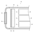
- FIG. 2 is a schematic cross-sectional view showing the cross section AA of FIG. 1
- 5 is a schematic cross-sectional view illustrating a gas flow when an abnormality occurs in the electricity storage device.
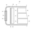
- FIG. This is a schematic cross-sectional view showing cross section AA of Figure 1 of a storage module, which is another example of an embodiment.
- the energy storage module 10 is used, for example, as a power source for an electric vehicle.
- the energy storage device of the present disclosure is not limited to being used as a power source for electric vehicles, and may be used, for example, as a power source for motor-driven electric devices such as power tools, power-assisted bicycles, electric motorcycles, electric wheelchairs, electric tricycles, and electric carts.
- the energy storage device of the present disclosure may also be used as a power source for various electric devices used indoors and outdoors, such as cleaners, radios, lighting devices, digital cameras, and video cameras.
- the energy storage module 10 includes a plurality of energy storage devices 20 and a housing 30 that houses the plurality of energy storage devices 20.
- the energy storage devices 20 discharge internal gas to one side in a first direction (longitudinal direction) in the event of an abnormality.
- a protective member 40 is provided on one side in the first direction of the energy storage device 20 that is disposed on the furthest side in the first direction inside the housing 30.
- a metal foam body 50 is provided on the other side in the first direction of the protective member 40 as a porous body having holes (through holes) that extend three-dimensionally. The metal foam body 50 can improve the reliability of the energy storage module 10, as will be described in detail below.
- the power storage device 20 is, for example, a cylindrical lithium ion secondary battery having electrodes on both end faces in the first direction (longitudinal direction).
- the power storage device of the present disclosure is not limited to the lithium ion secondary battery of this embodiment, and may be other secondary batteries such as nickel-metal hydride batteries, nickel-cadmium batteries, and lithium polymer batteries, or may be a power storage device such as a capacitor.
- the power storage device of the present disclosure is not limited to the cylindrical type of this embodiment, and may be a rectangular type.
- the energy storage device 20 comprises an electrode group in which a positive electrode and a negative electrode are wound facing each other with a separator between them, an exterior can that contains the electrode group together with an electrolyte and has a cylindrical portion and a bottom that closes one end of the cylindrical portion, and a sealing member that closes the opening at the other end of the exterior can.
- the sealing member is electrically connected to one of the positive electrode and the negative electrode via a lead or the like.
- the exterior can is electrically connected to the other of the positive electrode and the negative electrode via a lead or the like.
- An electrically insulating gasket is interposed between the sealing member and the exterior can.
- the energy storage device 20 has an exhaust section 21 at least at one end in a first direction (the longitudinal direction or the height direction of the energy storage device 20).
- the exhaust section 21 exhausts the internal gas to the outside when an abnormality occurs in the storage device 20.
- the storage device 20 exhausts gas to one side in the first direction when an abnormality occurs.
- the exhaust section 21 may be formed at both ends of the storage device 20 in the first direction.
- the exhaust section 21 may be, for example, an irreversible valve that opens by breaking an engraving, or a reversible valve that further compresses a compressed elastic body with gas pressure to form an exhaust path.
- all of the power storage devices 20 housed in the housing 30 are housed with the exhaust section 21 facing one side of the first direction.
- the multiple power storage devices disclosed herein are not limited to this embodiment, and it is sufficient that the exhaust section 21 of at least one power storage device 20 is housed so as to face one side of the first direction.
- the power storage module 10 may have a holder that holds the multiple power storage devices 20 in an aligned state.
- the housing 30 houses the power storage device 20 and protects the power storage device 20.
- the housing 30 has a cylindrical main body 31 with a longitudinal direction in the first direction, and lids 32, 33 that close both longitudinal ends of the main body 31.
- the housing 30 may close the openings at both ends with a waterproof structure by sandwiching ring-shaped packing between the opening of the main body 31 and the lids 32, 33.
- the housing 30 may close the openings at both ends of the main body 31 with a pair of lids 32, 33, but the main body 31 may be a cylindrical body with a bottom that is open only on one end face, and the end face opening may be closed only by the lid 32.
- the main body 31 is formed of a metal such as aluminum, and is strong and has excellent heat dissipation properties.
- the main body 31 is not limited to metal, and may be made of resin as long as it is a heat-resistant material.
- the main body 31 has a roughly rectangular cylindrical shape in cross section in the first direction, and is formed into a square cylindrical shape with both ends open.
- the main body 31 may have grooves or protrusions formed along the longitudinal direction to improve its strength.
- the surface of the main body 31 may be covered with a laminate film, vinyl, etc.
- the lids 32 and 33 are formed of hard plastic. However, the lids of the present disclosure are not limited to the hard plastic of this embodiment, and may be made of metal.
- the lid 32 is provided with an exhaust port 34, the details of which will be described later.
- One of the lids 32 and 33 may be provided with a discharge connector for discharging from the power storage device 20, or a charge connector for charging the power storage device 20.
- the exhaust port 34 connects the inside of the housing 30 housing the power storage device 20 to the outside, and exhausts gas discharged from the power storage device 20 from the inside to the outside.
- the exhaust port 34 is provided on one side in the first direction.
- the exhaust port of the present disclosure is not limited to this embodiment, and may be provided on the other side of the first direction, or on one or both sides in a direction perpendicular to the first direction.
- a porous body 35 is provided on both sides of the exhaust port 34 in the first direction. However, the porous body 35 may be provided only on one or the other side of the exhaust port 34 in the first direction.
- the porous body 35 may be, for example, a punched metal in which numerous through holes are formed in an aluminum plate. Each porous body 35 may be fixed to the lid 32 with screws and bolts. The porous body 35 can prevent particles of the contents of the power storage device 20 contained in the gas from being released to the outside of the housing 30 together with the gas. Furthermore, as the gas passes through the porous body 35, the heat of the gas is transferred to the porous body 35, and the gas that has passed through can be cooled.
- the protective member 40 is provided on one side in the first direction of the power storage device 20 arranged on the most one side in the first direction inside the housing 30. In other words, the protective member 40 is interposed between the power storage device 20 closest to the lid 32 and the porous body 35 in the first direction.
- the protective member 40 which will be described in detail later, blocks the gas and flame discharged from the power storage device 20 and can prevent the gas and flame from being directly blown onto the porous body 35.
- the protective member 40 can divert the gas discharged from the power storage device 20 and guide it to the exhaust port 34.
- the protective member 40 When viewed from the first direction, the protective member 40 is formed in a substantially rectangular shape that covers the multiple power storage devices 20 housed in the housing 30.
- the protective member 40 is formed in a plate shape with a thickness of, for example, 1 mm or less.
- the protective member 40 may be made of a material with a higher melting point than the porous body 35.
- the protective member 40 may be made of, for example, iron, stainless steel, or ceramics.
- the protective member 40 may be fixed to the lid 32 together with the porous body 35 by screws and bolts that fix the porous body 35 described above via a spacer that defines the distance between the protective member 40 and the porous body 35.
- the protective member 40 is made of a material that has a smaller opening rate than the metal foam 50 described below or has no through holes, it can block gas that attempts to pass through the protective member 40 by passing through the metal foam 50, thereby enhancing the filtering function of the metal foam 50.
- the metal foam 50 which is a porous body having holes (through holes) extending three-dimensionally, is provided on a surface of the protective member 40 facing the power storage device 20 in the first direction.
- the metal foam 50 is provided on one side in the first direction of the power storage device 20 that is disposed on the most one side in the first direction inside the housing 30.
- the metal foam 50 can function as a filter to capture the contents of the power storage device 20, cool the gas, and absorb the impact of the gas to improve reliability when gas is discharged from inside the power storage device 20 due to an abnormality in the power storage device 20.
- the metal foam 50 which is a porous body having holes (through holes) extending three-dimensionally, is a cellular structure of metal (stainless steel in this embodiment) having a large number of small spaces due to gas.
- the metal foam of the present disclosure is not limited to the stainless steel of this embodiment, and may be aluminum, nickel, or copper.
- the air bubble rate of the metal foam 50 is preferably 80 to 90%. In the metal foam 50, the air bubbles may be independent of each other or may be connected to each other.
- the metal foam 50 may be fixed to the protective member 40 by an adhesive. As a fixing method other than the adhesive, the metal foam 50 may be fixed to the protective member 40 by a screw, or may be sandwiched between the protective member 40 by a screw or the like.
- the foam may be mechanically engaged by crimping it to the protective member 40.
- the foam may also be attached to the protective member 40 by welding.
- examples of porous bodies include aggregates of metal particles aggregated with gaps between the particles.
- the thickness of the metal foam body 50 in the first direction is greater than the thickness of the protective member 40 in the first direction.
- the metal foam body 50 may be 1 mm or more.
- the shape of the metal foam body 50 viewed from the first direction may be substantially the same rectangular shape as the shape of the protective member 40 viewed from the first direction.
- the metal foam body 50 may be larger than the protective member 40. In this case, a non-facing portion that does not overlap with the protective member 40 in the first direction is formed in the metal foam body 50.
- the exhaust gas from the power storage device 20 can pass through the metal foam body 50, exit from this non-facing portion, and head toward the exhaust port 34.
- gas and flames are discharged from the exhaust section 21.
- the exhaust gas contains gas and particles of the contents of the power storage device 20.
- the gas discharged from the power storage device 20 is diffused by hitting the metal foam 50, and the shock wave generated when the gas is discharged is weakened.
- the metal foam 50 captures the particles contained in the gas.
- the gas that has entered the interior of the metal foam body 50 is cooled by the metal foam body 50 and flows in a detour in the second direction (a direction perpendicular to the first direction and parallel to the protective member 40) inside the metal foam body 50, and is cooled by the porous body 35 at the exhaust port 34.
- the porous body 35 captures particles that have not been captured by the metal foam body 50, and only the gas is discharged to the outside of the energy storage module 10.
- the end face of the metal foam body 50 in the second direction is exposed from the protective member 40.
- This configuration can encourage the movement of exhaust gas in the second direction within the metal foam body 50. Therefore, when attaching the metal foam body 50 to the protective member 40, it is preferable that there is no fixed point with the protective member 40 on at least one straight line among the multiple lines extending in the second direction. Even if fixed points are provided on all straight lines, it is preferable that the positions of the fixed points are shifted in the second direction.
- the energy storage module 10 As the capacity of the energy storage device 20 increases, the amount of gas discharged when the energy storage device 20 is abnormal has been increasing. As the amount of gas discharged from the energy storage device 20 increases, the time it takes to discharge gas containing high-temperature particles is becoming longer. As a result, for example, the protective member 40 is prone to becoming hot, and there is a risk that it may be eroded and damaged (holes may be opened) by the high-temperature particles.
- the gas may directly hit not only the protective member 40 that directly receives the gas, but also the porous body 35 of the exhaust port 34, which may melt or penetrate the porous body 35 of the exhaust port 34 as well, leading to the exhaust gas being released to the outside of the housing 30 while maintaining its high temperature and momentum.
- the metal foam 50 acts as a filter to capture high-temperature particles in the gas, cool the gas, and diffuse the impact of the gas, improving reliability.
- the gas penetrates into the metal foam body 50, and more high-temperature particles and the like in the gas are captured in the metal foam body 50. Furthermore, as described above, the gas that penetrates into the metal foam body 50 is blocked by the protective member 40 and flows around the protective member 40. This lengthens the flow path in the metal foam body 50, and more high-temperature particles and the like in the gas are captured in the metal foam body 50.
- the gas when gas is discharged due to an abnormality in the power storage device 20, the gas penetrates into the metal foam body 50, where the high-temperature gas is cooled.
- the gas that penetrates into the metal foam body 50 is blocked by the protective member 40 and flows around the protective member 40, which lengthens the flow path in the metal foam body 50, improving the cooling effect of the high-temperature gas in the metal foam body 50.
- the gas when gas is discharged due to an abnormality in the power storage device 20, the gas penetrates into the metal foam body 50 and is diffused. This makes it possible to prevent the protective member 40 from being damaged by the shock waves of the gas discharge.
- the metal foam 50 acts as a filter to capture high-temperature particles in the gas, cool the gas, and diffuse the impact of the gas, so the thickness of the protective member 40 can be made smaller than in a conventional energy storage module provided with only the protective member 40.
- the protective member 40 thinner and providing a lighter metal foam 50 than in a conventional energy storage module provided with only the protective member 40, the weight of the energy storage module 10 can be reduced.
- a metal foam body 70 is provided at the exhaust port 34 of the housing 30.
- the metal foam body 70 is interposed between the porous bodies 35 provided at the exhaust port 34.
- the present disclosure is not limited to this embodiment, and the metal foam body 70 may be provided in place of the porous body 35 on one side in the first direction.
- the metal foam body 70 is made of the same material as the metal foam body 50 described above.
- it is preferable that the shape of the metal foam body 70 when viewed from the first direction is approximately the same as the shape of the exhaust port 34.
- high-temperature particles in the gas that are not captured by the metal foam 50 can be reliably captured by the metal foam 70, and it is possible to prevent the high-temperature particles in the gas from being discharged to the outside of the energy storage module 10.
- the cooling effect of the gas passing through the exhaust port 34 can be improved.
- Configuration 1 A storage module including a plurality of power storage devices and a housing that houses the plurality of power storage devices, wherein the power storage devices discharge internal gas to one side in a first direction in the event of an abnormality, and a protective member is provided on one side of the power storage devices on one side of the first direction inside the housing, and a porous body having holes extending three-dimensionally is provided on the other side of the protective member in the first direction.
- Configuration 2 The energy storage module according to configuration 1, wherein the thickness of the porous body in the first direction is greater than the thickness of the protective member in the first direction.
- Configuration 3 The energy storage module according to configuration 1 or 2, wherein the shape of the porous body as viewed from the first direction is substantially the same as the shape of the protective member as viewed from the first direction.
- Configuration 4 The energy storage module according to any one of configurations 1 to 3, wherein the protective member has a smaller opening ratio than the porous body or has no through-holes.
- Configuration 5 The energy storage module described in any one of configurations 1 to 4, wherein an end face of the porous body is exposed from the protective member in a second direction perpendicular to the first direction.
- Configuration 6 The energy storage module described in any one of configurations 1 to 5, wherein in a second direction perpendicular to the first direction, the porous body has a portion extending from the protective member.
- Configuration 7 The energy storage module described in any one of configurations 1 to 6, wherein the porous body is a first foam, the housing has an exhaust port that connects an internal space of the housing that accommodates the energy storage device to the outside and exhausts gas discharged from the energy storage device from the internal space to the outside, and a second foam is provided in the exhaust port.
Landscapes
- Chemical & Material Sciences (AREA)
- Chemical Kinetics & Catalysis (AREA)
- Electrochemistry (AREA)
- General Chemical & Material Sciences (AREA)
- Battery Mounting, Suspending (AREA)
- Electric Double-Layer Capacitors Or The Like (AREA)
Priority Applications (3)
| Application Number | Priority Date | Filing Date | Title |
|---|---|---|---|
| CN202480012138.5A CN120677585A (zh) | 2023-02-28 | 2024-02-28 | 蓄电模块 |
| JP2025503956A JPWO2024181475A1 (https=) | 2023-02-28 | 2024-02-28 | |
| EP24763954.5A EP4675819A1 (en) | 2023-02-28 | 2024-02-28 | Power storage module |
Applications Claiming Priority (2)
| Application Number | Priority Date | Filing Date | Title |
|---|---|---|---|
| JP2023030478 | 2023-02-28 | ||
| JP2023-030478 | 2023-02-28 |
Publications (1)
| Publication Number | Publication Date |
|---|---|
| WO2024181475A1 true WO2024181475A1 (ja) | 2024-09-06 |
Family
ID=92589867
Family Applications (1)
| Application Number | Title | Priority Date | Filing Date |
|---|---|---|---|
| PCT/JP2024/007203 Ceased WO2024181475A1 (ja) | 2023-02-28 | 2024-02-28 | 蓄電モジュール |
Country Status (4)
| Country | Link |
|---|---|
| EP (1) | EP4675819A1 (https=) |
| JP (1) | JPWO2024181475A1 (https=) |
| CN (1) | CN120677585A (https=) |
| WO (1) | WO2024181475A1 (https=) |
Citations (5)
| Publication number | Priority date | Publication date | Assignee | Title |
|---|---|---|---|---|
| JP2019169454A (ja) | 2018-03-26 | 2019-10-03 | パナソニックIpマネジメント株式会社 | 電池パック及び電動自転車 |
| JP2021093295A (ja) * | 2019-12-10 | 2021-06-17 | パナソニックIpマネジメント株式会社 | 電動工具用電池パック、及び電動工具 |
| WO2021200941A1 (ja) * | 2020-03-31 | 2021-10-07 | パナソニックIpマネジメント株式会社 | 電池パック |
| WO2022024713A1 (ja) * | 2020-07-31 | 2022-02-03 | パナソニックIpマネジメント株式会社 | 電池ケース、及び電池パック |
| WO2024005034A1 (ja) * | 2022-06-30 | 2024-01-04 | パナソニックIpマネジメント株式会社 | 蓄電モジュール |
-
2024
- 2024-02-28 JP JP2025503956A patent/JPWO2024181475A1/ja active Pending
- 2024-02-28 EP EP24763954.5A patent/EP4675819A1/en active Pending
- 2024-02-28 WO PCT/JP2024/007203 patent/WO2024181475A1/ja not_active Ceased
- 2024-02-28 CN CN202480012138.5A patent/CN120677585A/zh active Pending
Patent Citations (5)
| Publication number | Priority date | Publication date | Assignee | Title |
|---|---|---|---|---|
| JP2019169454A (ja) | 2018-03-26 | 2019-10-03 | パナソニックIpマネジメント株式会社 | 電池パック及び電動自転車 |
| JP2021093295A (ja) * | 2019-12-10 | 2021-06-17 | パナソニックIpマネジメント株式会社 | 電動工具用電池パック、及び電動工具 |
| WO2021200941A1 (ja) * | 2020-03-31 | 2021-10-07 | パナソニックIpマネジメント株式会社 | 電池パック |
| WO2022024713A1 (ja) * | 2020-07-31 | 2022-02-03 | パナソニックIpマネジメント株式会社 | 電池ケース、及び電池パック |
| WO2024005034A1 (ja) * | 2022-06-30 | 2024-01-04 | パナソニックIpマネジメント株式会社 | 蓄電モジュール |
Also Published As
| Publication number | Publication date |
|---|---|
| EP4675819A1 (en) | 2026-01-07 |
| JPWO2024181475A1 (https=) | 2024-09-06 |
| CN120677585A (zh) | 2025-09-19 |
Similar Documents
| Publication | Publication Date | Title |
|---|---|---|
| CN114175365B (zh) | 电池及其相关装置、制备方法和制备设备 | |
| JP7418405B2 (ja) | 電池モジュール | |
| KR102818715B1 (ko) | 배터리 및 관련 장치, 제조 방법 및 제조 장치 | |
| CN115715438B (zh) | 电池单体及其制造方法和制造系统、电池以及用电装置 | |
| EP2654100B1 (en) | Battery pack | |
| CN114175376B (zh) | 电池及其相关装置、制备方法和制备设备 | |
| CN114175377A (zh) | 电池及其相关装置、制备方法和制备设备 | |
| US8007933B2 (en) | Vehicle power storage unit and vehicle | |
| CN213026307U (zh) | 电池、包括电池的装置和制备电池的设备 | |
| CN213636145U (zh) | 电池、包括电池的装置和制备电池的设备 | |
| EP4485655B1 (en) | Battery and electric device | |
| KR20150066077A (ko) | 배터리 모듈 | |
| CN103227311A (zh) | 密闭型二次电池 | |
| JP2023528296A (ja) | 電池、電力消費装置、電池を製造する方法と装置 | |
| US20250357623A1 (en) | Battery and electric device | |
| KR20220163202A (ko) | 배터리 팩, 및 그것을 포함하는 자동차 | |
| US20230246287A1 (en) | End cap assembly, battery cell, battery, and electrical device | |
| CN218939874U (zh) | 电池及用电装置 | |
| EP4593181A1 (en) | Battery and electric apparatus | |
| CN209709060U (zh) | 电池模块和电池包 | |
| CN221379537U (zh) | 电池单体、电池、用电设备、制造电池单体的装置 | |
| KR20190013034A (ko) | 배터리 케이스와 이를 포함하는 배터리 팩 및 자동차 | |
| JPH0737568A (ja) | 非水電解質二次電池用安全弁 | |
| WO2024181475A1 (ja) | 蓄電モジュール | |
| CN223451108U (zh) | 电池单体、电池装置和用电装置 |
Legal Events
| Date | Code | Title | Description |
|---|---|---|---|
| 121 | Ep: the epo has been informed by wipo that ep was designated in this application |
Ref document number: 24763954 Country of ref document: EP Kind code of ref document: A1 |
|
| WWE | Wipo information: entry into national phase |
Ref document number: 202480012138.5 Country of ref document: CN |
|
| ENP | Entry into the national phase |
Ref document number: 2025503956 Country of ref document: JP Kind code of ref document: A |
|
| WWE | Wipo information: entry into national phase |
Ref document number: 2025503956 Country of ref document: JP |
|
| WWP | Wipo information: published in national office |
Ref document number: 202480012138.5 Country of ref document: CN |
|
| WWE | Wipo information: entry into national phase |
Ref document number: 2024763954 Country of ref document: EP |
|
| NENP | Non-entry into the national phase |
Ref country code: DE |
|
| ENP | Entry into the national phase |
Ref document number: 2024763954 Country of ref document: EP Effective date: 20250929 |
|
| ENP | Entry into the national phase |
Ref document number: 2024763954 Country of ref document: EP Effective date: 20250929 |
|
| ENP | Entry into the national phase |
Ref document number: 2024763954 Country of ref document: EP Effective date: 20250929 |
|
| WWP | Wipo information: published in national office |
Ref document number: 2024763954 Country of ref document: EP |